EP4148366A1 - Échangeur de chaleur - Google Patents
Échangeur de chaleur Download PDFInfo
- Publication number
- EP4148366A1 EP4148366A1 EP21195549.7A EP21195549A EP4148366A1 EP 4148366 A1 EP4148366 A1 EP 4148366A1 EP 21195549 A EP21195549 A EP 21195549A EP 4148366 A1 EP4148366 A1 EP 4148366A1
- Authority
- EP
- European Patent Office
- Prior art keywords
- openings
- primary
- heat exchanger
- fluid
- plates
- Prior art date
- Legal status (The legal status is an assumption and is not a legal conclusion. Google has not performed a legal analysis and makes no representation as to the accuracy of the status listed.)
- Pending
Links
- 239000012530 fluid Substances 0.000 claims abstract description 84
- 230000000295 complement effect Effects 0.000 claims abstract description 6
- 239000002826 coolant Substances 0.000 claims description 49
- 239000003507 refrigerant Substances 0.000 claims description 45
- 239000007788 liquid Substances 0.000 claims description 6
- 238000000926 separation method Methods 0.000 claims description 6
- 238000000034 method Methods 0.000 description 5
- RWRIWBAIICGTTQ-UHFFFAOYSA-N difluoromethane Chemical compound FCF RWRIWBAIICGTTQ-UHFFFAOYSA-N 0.000 description 3
- 239000000203 mixture Substances 0.000 description 2
- 238000011144 upstream manufacturing Methods 0.000 description 2
- 238000005192 partition Methods 0.000 description 1
- 238000004080 punching Methods 0.000 description 1
- XLYOFNOQVPJJNP-UHFFFAOYSA-N water Substances O XLYOFNOQVPJJNP-UHFFFAOYSA-N 0.000 description 1
Images


Classifications
-
- F—MECHANICAL ENGINEERING; LIGHTING; HEATING; WEAPONS; BLASTING
- F28—HEAT EXCHANGE IN GENERAL
- F28D—HEAT-EXCHANGE APPARATUS, NOT PROVIDED FOR IN ANOTHER SUBCLASS, IN WHICH THE HEAT-EXCHANGE MEDIA DO NOT COME INTO DIRECT CONTACT
- F28D9/00—Heat-exchange apparatus having stationary plate-like or laminated conduit assemblies for both heat-exchange media, the media being in contact with different sides of a conduit wall
- F28D9/0031—Heat-exchange apparatus having stationary plate-like or laminated conduit assemblies for both heat-exchange media, the media being in contact with different sides of a conduit wall the conduits for one heat-exchange medium being formed by paired plates touching each other
- F28D9/0043—Heat-exchange apparatus having stationary plate-like or laminated conduit assemblies for both heat-exchange media, the media being in contact with different sides of a conduit wall the conduits for one heat-exchange medium being formed by paired plates touching each other the plates having openings therein for circulation of at least one heat-exchange medium from one conduit to another
- F28D9/005—Heat-exchange apparatus having stationary plate-like or laminated conduit assemblies for both heat-exchange media, the media being in contact with different sides of a conduit wall the conduits for one heat-exchange medium being formed by paired plates touching each other the plates having openings therein for circulation of at least one heat-exchange medium from one conduit to another the plates having openings therein for both heat-exchange media
-
- F—MECHANICAL ENGINEERING; LIGHTING; HEATING; WEAPONS; BLASTING
- F25—REFRIGERATION OR COOLING; COMBINED HEATING AND REFRIGERATION SYSTEMS; HEAT PUMP SYSTEMS; MANUFACTURE OR STORAGE OF ICE; LIQUEFACTION SOLIDIFICATION OF GASES
- F25B—REFRIGERATION MACHINES, PLANTS OR SYSTEMS; COMBINED HEATING AND REFRIGERATION SYSTEMS; HEAT PUMP SYSTEMS
- F25B39/00—Evaporators; Condensers
- F25B39/02—Evaporators
- F25B39/022—Evaporators with plate-like or laminated elements
-
- F—MECHANICAL ENGINEERING; LIGHTING; HEATING; WEAPONS; BLASTING
- F25—REFRIGERATION OR COOLING; COMBINED HEATING AND REFRIGERATION SYSTEMS; HEAT PUMP SYSTEMS; MANUFACTURE OR STORAGE OF ICE; LIQUEFACTION SOLIDIFICATION OF GASES
- F25B—REFRIGERATION MACHINES, PLANTS OR SYSTEMS; COMBINED HEATING AND REFRIGERATION SYSTEMS; HEAT PUMP SYSTEMS
- F25B39/00—Evaporators; Condensers
- F25B39/04—Condensers
-
- F—MECHANICAL ENGINEERING; LIGHTING; HEATING; WEAPONS; BLASTING
- F28—HEAT EXCHANGE IN GENERAL
- F28D—HEAT-EXCHANGE APPARATUS, NOT PROVIDED FOR IN ANOTHER SUBCLASS, IN WHICH THE HEAT-EXCHANGE MEDIA DO NOT COME INTO DIRECT CONTACT
- F28D21/00—Heat-exchange apparatus not covered by any of the groups F28D1/00 - F28D20/00
- F28D2021/0019—Other heat exchangers for particular applications; Heat exchange systems not otherwise provided for
- F28D2021/008—Other heat exchangers for particular applications; Heat exchange systems not otherwise provided for for vehicles
- F28D2021/0084—Condensers
-
- F—MECHANICAL ENGINEERING; LIGHTING; HEATING; WEAPONS; BLASTING
- F28—HEAT EXCHANGE IN GENERAL
- F28F—DETAILS OF HEAT-EXCHANGE AND HEAT-TRANSFER APPARATUS, OF GENERAL APPLICATION
- F28F3/00—Plate-like or laminated elements; Assemblies of plate-like or laminated elements
- F28F3/02—Elements or assemblies thereof with means for increasing heat-transfer area, e.g. with fins, with recesses, with corrugations
- F28F3/04—Elements or assemblies thereof with means for increasing heat-transfer area, e.g. with fins, with recesses, with corrugations the means being integral with the element
- F28F3/042—Elements or assemblies thereof with means for increasing heat-transfer area, e.g. with fins, with recesses, with corrugations the means being integral with the element in the form of local deformations of the element
- F28F3/046—Elements or assemblies thereof with means for increasing heat-transfer area, e.g. with fins, with recesses, with corrugations the means being integral with the element in the form of local deformations of the element the deformations being linear, e.g. corrugations
-
- F—MECHANICAL ENGINEERING; LIGHTING; HEATING; WEAPONS; BLASTING
- F28—HEAT EXCHANGE IN GENERAL
- F28F—DETAILS OF HEAT-EXCHANGE AND HEAT-TRANSFER APPARATUS, OF GENERAL APPLICATION
- F28F9/00—Casings; Header boxes; Auxiliary supports for elements; Auxiliary members within casings
- F28F9/02—Header boxes; End plates
- F28F9/026—Header boxes; End plates with static flow control means, e.g. with means for uniformly distributing heat exchange media into conduits
- F28F9/028—Header boxes; End plates with static flow control means, e.g. with means for uniformly distributing heat exchange media into conduits by using inserts for modifying the pattern of flow inside the header box, e.g. by using flow restrictors or permeable bodies or blocks with channels
Definitions
- the present invention relates to a heat exchanger.
- this invention relates to the heat exchanger having two sets of heat exchange plates with different cross-sections of openings to enable optimum heat exchange between the two fluids flowing therein.
- Plate-type heat exchangers may include a plurality of plates stacked together to form two fluid channels.
- the two fluid channels are fluidically isolated from each other, yet thermal coupled with each other.
- adjacent plates of the stacked plates delimit the paths for the fluid channels.
- the fluid channels are alternately formed on each other to form the core of the heat exchanger.
- the fluid channels can be refrigerant and coolant channels. Both the channels are in heat-exchange configuration to enable heat exchange between the fluids in the refrigerant channel and the coolant channel.
- Each plate may include openings for enabling fluid flow into the respective fluid channels.
- the openings provided in the stack of plates form conduits that transfers the fluid to the respective fluid channels.
- the openings forming the conduits may act as a manifold to enable fluid flow into the respective channels. Further, the openings may include collars to fluidically connect the conduits with the respective fluid channels.
- the plate may include the openings for refrigerant flow, referred to as refrigerant openings and the opening for coolant flow, referred to as coolant openings.
- the refrigerant openings and coolant openings formed on the plates are adapted to form the respective manifolds to enable refrigerant flow in the refrigerant channels and the coolant flow in the coolant channels.
- the openings generally can be circular openings or any other shape.
- the refrigerant openings and coolant openings formed in the plates are of same cross-section.
- the cross-section of the refrigerant openings is same as the cross-section of the coolant openings.
- diameter of the refrigerant openings is same as the diameter of the coolant openings.
- the coolant manifold and the refrigerant manifold may carry same volume of the respective fluid in the respective manifold.
- refrigerant such as difluoromethane (also called difluroromethylene, or R-32) and coolant such as water-glycol mixture may have different thermophysical properties.
- the refrigerant manifold and the coolant manifold are having uniform volume of fluid flowing therein. Therefore, the coolant flowing into the coolant channels and the refrigerant flowing into the refrigerant channels are having uniform.
- the heat exchange between the refrigerant and the coolant is sub-optimum, as phase change temperature of both the refrigerant and the coolant are different. As a result, thermal performance of the heat exchanger is reduced.
- pressure drop and flow of the refrigerant flowing into the refrigerant channel is controlled.
- controlling flow of the refrigerant is cumbersome, as the refrigerant flows in high pressure; it requires complex techniques to control the flow of the refrigerant.
- some elements or parameters may be indexed, such as a first element and a second element.
- this indexation is only meant to differentiate and name elements, which are similar but not identical. No idea of priority should be inferred from such indexation, as these terms may be switched without betraying the invention. Additionally, this indexation does not imply any order in mounting or use of the elements of the invention.
- an embodiment provides a heat exchanger for heat exchange between a first fluid and at least one second fluid.
- the heat exchanger includes a stack of primary plates forming at least one first channel for the first fluid and at least one second channel for the second fluid.
- the primary plates comprise primary openings having a first cross-section and the primary openings being configured to form first manifolds for enabling first fluid circulation in the first channels and second manifolds for enabling second fluid circulation in the second channels.
- the heat exchanger further comprises at least one secondary plate disposed between the consecutive stacks of primary plates.
- the secondary plate comprises secondary openings having a second cross-section. The secondary openings are complementary to and fluidically connected to the primary openings forming the first and second manifolds.
- the first cross-section is different from the second cross-section.
- the second cross-section of the secondary opening is smaller than the first cross-section of the primary openings formed in the primary plates.
- the secondary openings of the secondary plates are coaxial to the primary openings providing fluid to the second channels.
- the secondary opening is formed on the secondary plate at an inlet manifold amongst the second manifolds of the second channel.
- the secondary opening is formed on the secondary plate at an outlet manifold amongst the second manifolds of the second channel.
- the secondary opening is formed on the secondary plate at the both inlet and outlet manifolds amongst the second manifolds of the second channel.
- the primary openings and the secondary openings are in-line to each other to enable fluidal connection between the primary openings and the secondary openings.
- the heat exchanger includes at least one separation plate having at least one baffle, and the separation plate being located in between two primary plates to define two fluid flow paths for the first channel and the second channel.
- the heat exchanger includes at least one cover plate provided in-contact with the primary plates to encapsulate at least a portion of the primary plates.
- the cover plate further comprising cover-openings complementary to the primary openings and the secondary opening formed on the primary and secondary plates respectively.
- the primary plates comprise corrugations on its surface.
- the heat exchanger is configured for an operation as condenser, the first fluid being a refrigerant and the second fluid being a liquid coolant.
- the present invention relates to a plate-type heat exchanger having two sets of heat exchange plates with different cross-sections of openings to enable optimum heat exchange between the two fluid flowing therein.
- the conventional plate heat exchangers usually comprise a stack of plates forming the refrigerant and coolant channels.
- the plates may include openings forming manifolds for enabling refrigerant and coolant flow into the respective channels.
- the openings are of same cross-section for both refrigerant and coolant manifolds.
- flow rate of the refrigerant and the coolant into their respective manifolds is same.
- thermo-physical properties of the refrigerant and the coolant are different, heat exchange between the refrigerant and the coolant is inefficient or sub-optimal.
- phase temperature of the coolant and the refrigerant is different. It is possible that the heat exchange between the refrigerant and the coolant cannot be optimum in the heat exchanger in case the coolant and refrigerant is flowing at same flow rate and volume into their respective channels.
- pressure drop of the refrigerant is increased, however, such technique is still inefficient to achieve optimum heat exchange between both the refrigerant and coolant.
- Such technique has some energy loss and requires more energy to create the pressure drop of the refrigerant.
- the present invention provides a technique to control the coolant flow in the heat exchanger to optimize heat exchange between the refrigerant and the coolant. As a result, thermal performance of the heat exchanger can be increased. Further, the geometry and design of the present invention are described with the forthcoming figures.
- Figs. 1 to 3 illustrate different views a plate heat exchanger 100, in accordance with an embodiment of the present invention.
- Fig. 1 shows a schematic view of the heat exchanger 100
- Figs. 2 and 3 show different cross-sectional views of the heat exchanger 100 of Fig. 1 .
- the heat exchanger 100 may be configured for the heat exchange between a first fluid and a second fluid, for example, a refrigerant and a liquid coolant.
- the liquid coolant can be water or water-glycol mixture.
- the heat exchanger 100 may be configured for an operation as a condenser, here the first fluid being a refrigerant and the second fluid being a liquid coolant.
- the heat exchanger 100 may comprise a plurality of primary plates 102 stacked together to form at least two fluid channels, namely, first channels 102A being refrigerant channels and second channels 102B being liquid coolant channels.
- the primary plates 102 are corrugated plates.
- the primary plates 102 may have corrugations on its surface. Generally, the corrugations on the primary plates 102 are to increase pressure drop of the first fluid and the second fluid in order to optimize the thermal performance of the heat exchanger 100.
- the first channels 102A and the second channels 102B are alternately formed with each other by the primary plates 102.
- the primary plates 102 are stacked together so as to delimit one first channel 102A by a bottom surface of a first plate and a top surface of a second plate and to delimit one second channel 102B by a bottom surface of the second plate and a top surface of a third plate.
- the primary plates 102 are brazed together into a stack without disturbing the fluid channels formed therein.
- at least a portion of the top surface of one plate is brazed to at least a portion of the bottom surface of the adjacent plate without disturbing the fluid flow path defined therein.
- the primary plates 102 may comprise primary openings 104, 106 forming first manifolds 104A and second manifolds 106A to enable fluid flow in the first channels 102A and the second channels 102B, respectively.
- the first manifolds 104A are refrigerant manifolds and the second manifolds 106A are coolant manifolds.
- the primary openings 104, 106 may comprise a first cross-section "D1".
- the primary openings 104, 106 are circular in shape.
- the first cross-section D1 refers to the diameter of the circle forming the openings.
- the primary openings 104, 106 are non-circular in shape.
- the first cross-section D1 refers to the hydraulic diameter of the openings.
- the primary openings 104, 106 may be classified into two sets of openings, a first set of primary openings 104 enabling the first fluid circulation in the first channels 102A and a second set of primary openings 106 enabling the second fluid circulation in the second channels 102B.
- the first set of primary openings 104 forming the first manifold 104A is to introduce and receive the first fluid to/ from the first channels 102A respectively.
- the first fluid, i.e., the refrigerant, flowing into the heat exchanger 100 is referred to as "REF_IN” and the first fluid flowing out from the heat exchanger 100 is referred to as "REF_OUT”.
- the second set of primary openings 106 forming the second manifold 106A is to introduce and receive the second fluid to orfrom the second channels 102B respectively.
- the second fluid, i.e., the coolant flowing into the heat exchanger 100 is referred to as "COOL_IN” and the first fluid flowing out from the heat exchanger 100 is referred to as "COOL_OUT” in the Figs. 2 and 3 .
- the primary openings 104, 106 may further comprise collars configured to promote laminar fluid flow between the manifolds 104A, 106A and the respective fluid channels 102A-B.
- the heat exchanger 100 includes at least one cover plate 110 provided in contact with the primary plates 102 to encapsulate at least a portion of the primary plates 102.
- the cover plate 110 includes cover-openings complementary to the primary openings 104, 106 and the secondary opening 204 formed on the primary and secondary plates 102, 202 respectively.
- the heat exchanger 100 further includes a separation plate 110 having a baffle. The separation plate 110 may be located in between two primary plates 102 to define two fluid flow paths for the first channel 102A and the second channel 102B.
- Fig. 3 is a cross-section view of the heat exchanger 100 showing the coolant flow path inside the heat exchanger 100.
- the heat exchanger 100 may further comprise at least one secondary plate 202 disposed between the consecutive stack of primary plates 102.
- the secondary plate 202 may comprise secondary openings 204 having a second cross-section "D2".
- the cross-section of the secondary openings 204 is referred to as a second cross-section "D2".
- the secondary openings 204 are circular in shape.
- the second cross-section D2 refers to the diameter of the circle forming the openings.
- the secondary openings 204 are non-circular in shape.
- the second cross-section D2 refers to the hydraulic diameter of the openings
- first cross-section "D1" of the primary openings 104, 106 is different from the second cross-section "D2" of the secondary openings 204.
- first cross-section "D1" of the primary openings 104, 106 is greater than the second cross-section "D2" of the secondary openings 204.
- second cross-section "D2" is smaller than the first cross-section "D1”.
- the secondary opening 204 is in-line to the second set of primary openings 106 of the primary plates 102 forming the second manifolds 106A.
- the secondary openings 204 of the secondary plates 202 are coaxial to the second set of primary openings 106 of the primary plates 102.
- the secondary openings 204 are defined in-line to the second set of primary openings 106 forming the second manifolds 106A.
- the coolant flow into the heat exchanger 100 is controlled.
- the pressure drop of the coolant is increased at the first channels 102A disposed downstream to the secondary plate 202, thereby optimizing the heat exchange between the coolant and refrigerant.
- the secondary openings 204 may be in-line with the second manifold 106A introducing the coolant the second channels 102B.
- the secondary openings 204 may be in-line with the second manifold 106A receiving the coolant from the second channels 102B. In yet another example, the secondary openings 204 may be provided on both the second manifold 106A providing the coolant to the second channels 102B and the second manifold 106A receiving the coolant from the second channels 102A.
- Figs. 4 and 5 illustrate schematic views of the primary standalone plate 102 and the secondary standalone plate 202 respectively of Fig. 1 .
- the first set of primary openings 104 is formed on opposite ends of the primary plate 102.
- the first set of primary openings 104 providing the first fluid to the first channel 102A is formed on a first end 108A of the primary plates 102
- the first set of primary openings 104 receiving the first fluid from the first channels 102A is formed on a second end 108B of the primary plates 102.
- the second set of primary openings 106 is formed on opposite ends of the primary plates 102.
- the second set of primary openings 106 providing the second fluid to the second channel 102B is formed on the first end 108A of the primary plates 102, whereas the second set of openings 204 receiving the second fluid from the second channels 102B is formed on the second end 108B of the plates 102.
- first set of primary openings 104 providing the first fluid to the first channel 102A and the first set of primary openings 104 receiving the first fluid from the first channel 102A are formed on same end of the primary plates 102, i.e. either on the first end 108A or the second end 108B of the primary plates 102.
- second set of primary openings 106 enabling the second fluid circulation in the second channel 102B are formed on same end of the primary plates 102.
- each of the first channel 102A and the second channel 102B may require a partition plate to enable two-pass flow in the heat exchanger 100.
- the above-mentioned embodiment is not shown in any of the figures.
- the secondary plate 202 may include the first set of primary openings 104 to enable the refrigerant circulation in the first channel 102A. Further, the secondary openings 204 formed on the secondary plate 202 are coaxial to the second set of primary openings 106. As the secondary openings 204 are having different cross-section than the second set of primary openings 106, the second fluid, i.e. coolant, flow in the second channel 102B is controlled. As mentioned above, the primary openings 106 and the secondary openings 204 can be of a circular shape.
- the shape of the primary openings 106 and the secondary openings 204 are in the circular shape, it is possible to design the openings in non-circular shapes having a hydraulic diameter and such diameter of the openings is referred to as the cross-section of the openings.
- the primary openings 104, 106 and the secondary openings 204 are of a circular shape.
- the cross-section of the openings means the diameter of the openings.
- the cross-section "D1" of the primary openings 104, 106 is different from the cross-section "D2" of the secondary openings 204.
- the diameter "D2" of the secondary openings 204 is smaller than the diameter "D1" of the primary openings 104, 106.
- the primary openings 104, 106 and the secondary openings 204 are formed by punching the primary plates 102 and the secondary plates 202 respectively.
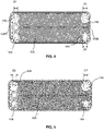
- Fig. 6 to 8 illustrate exploded views of the primary plates 102 and the secondary plates 202 of the heat exchanger 100 of Fig. 1 according to various embodiments of the present invention.
- Fig. 6 is an exploded view of the primary plates 102 and the secondary plates 202 having the secondary openings 204 at the inlet manifold amongst the second manifolds 106A of the heat exchanger 100.
- Fig. 7 is another exploded view of the primary plates 102 and the secondary plates 202 having the secondary openings 204 at the outlet manifold amongst the second manifolds 106A of the heat exchanger 100.
- Fig. 8 is another exploded view of the primary plates 102 and the secondary plates 202 having the secondary openings 204 at both the inlet and outlet manifolds amongst the second manifolds 106A of the heat exchanger 100.
- the secondary openings 204 can formed on the secondary plate 202 at the inlet manifold amongst the second manifolds106A as shown in Fig. 6 .
- the secondary openings 204 are formed on the secondary plates 202 at the second manifold 106A introducing the second fluid to the second channels 102B.
- the secondary opening 204 is coaxial to the secondary manifold 106A providing the second fluid to the second channels 102B.
- the secondary openings 204 may be formed on the secondary plate 202 at the outlet manifold amongst the second manifolds106A, as shown in Fig. 7 .
- the secondary openings 204 may be formed on the secondary plates at the second manifold 106A receiving the second fluid from the second channels 102B.
- the secondary opening 204 is coaxial to the secondary manifold 106A receiving the second fluid from the second channels 102B.
- the secondary openings 204 can be formed on the secondary plate 202 at both inlet and outlet manifolds amongst the second manifolds106A as shown in Fig. 8 .
- the secondary openings 204 may be formed on the secondary plates at the second manifold 106A introducing the second fluid to the second channels 102B and receiving the second fluid from the second channels 102B.
- the secondary opening 204 is coaxial to the secondary manifold 106A.
- the pressure drop of the second fluid, i.e. coolant is different between the second channels 102B upstream to the secondary plate 202 and the second channels 102B downstream to the secondary plate 202.
- the pressure drop of second fluid in the second channels 102B upstream to the secondary plate 202 is lower than the pressure drop of second fluid in the second channels 102B downstream to the secondary plate 202. Therefore, the second fluid flowing into the heat exchanger 100 can be controlled and the volume of the second fluid flowing into the second channels 102B is less than of volume of the first fluid flowing into the first channels 102A. As a result, heat exchange between the first and second fluids can be optimized, thereby increasing thermal performance of the heat exchanger 100.
Priority Applications (1)
| Application Number | Priority Date | Filing Date | Title |
|---|---|---|---|
| EP21195549.7A EP4148366A1 (fr) | 2021-09-08 | 2021-09-08 | Échangeur de chaleur |
Applications Claiming Priority (1)
| Application Number | Priority Date | Filing Date | Title |
|---|---|---|---|
| EP21195549.7A EP4148366A1 (fr) | 2021-09-08 | 2021-09-08 | Échangeur de chaleur |
Publications (1)
| Publication Number | Publication Date |
|---|---|
| EP4148366A1 true EP4148366A1 (fr) | 2023-03-15 |
Family
ID=77666384
Family Applications (1)
| Application Number | Title | Priority Date | Filing Date |
|---|---|---|---|
| EP21195549.7A Pending EP4148366A1 (fr) | 2021-09-08 | 2021-09-08 | Échangeur de chaleur |
Country Status (1)
| Country | Link |
|---|---|
| EP (1) | EP4148366A1 (fr) |
Citations (3)
| Publication number | Priority date | Publication date | Assignee | Title |
|---|---|---|---|---|
| EP0765461A1 (fr) * | 1994-06-20 | 1997-04-02 | Flatplate, Inc. | Echangeur de chaleur a plaques superposees presentant trois circuits |
| US6305466B1 (en) * | 1998-03-11 | 2001-10-23 | Swep International Ab | Three circuit plate heat exchanger |
| US20190063846A1 (en) * | 2017-08-31 | 2019-02-28 | Dana Canada Corporation | Multi-Fluid Heat Exchanger |
-
2021
- 2021-09-08 EP EP21195549.7A patent/EP4148366A1/fr active Pending
Patent Citations (3)
| Publication number | Priority date | Publication date | Assignee | Title |
|---|---|---|---|---|
| EP0765461A1 (fr) * | 1994-06-20 | 1997-04-02 | Flatplate, Inc. | Echangeur de chaleur a plaques superposees presentant trois circuits |
| US6305466B1 (en) * | 1998-03-11 | 2001-10-23 | Swep International Ab | Three circuit plate heat exchanger |
| US20190063846A1 (en) * | 2017-08-31 | 2019-02-28 | Dana Canada Corporation | Multi-Fluid Heat Exchanger |
Similar Documents
| Publication | Publication Date | Title |
|---|---|---|
| EP1869391B1 (fr) | Echangeur thermique a plaques | |
| US4274482A (en) | Laminated evaporator | |
| US6170568B1 (en) | Radial flow heat exchanger | |
| JP6349465B2 (ja) | 円弧状板型熱交換器 | |
| CN107664444B (zh) | 侧流程板壳式换热板以及多流程可拆卸板壳式换热器 | |
| JP4454779B2 (ja) | プレート式熱交換器 | |
| EP3392592A1 (fr) | Structure de régulation d'écoulement d'entrée et échangeur de chaleur à plaques | |
| US6814135B2 (en) | Stacked-type evaporator | |
| EP4148366A1 (fr) | Échangeur de chaleur | |
| JPH0493596A (ja) | 積層型熱交換器のコア部構造 | |
| EP2990749B1 (fr) | Échangeur de chaleur | |
| EP3872435B1 (fr) | Échangeur de chaleur | |
| EP3572743B1 (fr) | Ensemble échangeur de chaleur | |
| CN111765786A (zh) | 换热器与换热器组件 | |
| JPH11281287A (ja) | 熱交換器 | |
| EP4194787A1 (fr) | Échangeur de chaleur | |
| CN220624999U (zh) | 换热板片及板式换热器 | |
| EP4166887A1 (fr) | Échangeur de chaleur | |
| JP2000304475A (ja) | 積層式熱交換器 | |
| CN214095637U (zh) | 换热器扁管及换热器 | |
| JPH02171591A (ja) | 積層形熱交換器 | |
| KR20190075679A (ko) | 쉘앤플레이트 열교환기용 쉘 및 이를 구비한 쉘앤플레이트 열교환기 | |
| WO2024002198A1 (fr) | Échangeur de chaleur de batterie d'alimentation, système de batterie d'alimentation et véhicule électrique | |
| EP4148367A1 (fr) | Échangeur thermique à plaques | |
| JP4164145B2 (ja) | 熱交換器、及びこれを用いたカー・エアコン |
Legal Events
| Date | Code | Title | Description |
|---|---|---|---|
| PUAI | Public reference made under article 153(3) epc to a published international application that has entered the european phase |
Free format text: ORIGINAL CODE: 0009012 |
|
| STAA | Information on the status of an ep patent application or granted ep patent |
Free format text: STATUS: THE APPLICATION HAS BEEN PUBLISHED |
|
| AK | Designated contracting states |
Kind code of ref document: A1 Designated state(s): AL AT BE BG CH CY CZ DE DK EE ES FI FR GB GR HR HU IE IS IT LI LT LU LV MC MK MT NL NO PL PT RO RS SE SI SK SM TR |
|
| STAA | Information on the status of an ep patent application or granted ep patent |
Free format text: STATUS: REQUEST FOR EXAMINATION WAS MADE |
|
| 17P | Request for examination filed |
Effective date: 20230901 |
|
| RBV | Designated contracting states (corrected) |
Designated state(s): AL AT BE BG CH CY CZ DE DK EE ES FI FR GB GR HR HU IE IS IT LI LT LU LV MC MK MT NL NO PL PT RO RS SE SI SK SM TR |
|
| GRAP | Despatch of communication of intention to grant a patent |
Free format text: ORIGINAL CODE: EPIDOSNIGR1 |
|
| STAA | Information on the status of an ep patent application or granted ep patent |
Free format text: STATUS: GRANT OF PATENT IS INTENDED |
|
| RIC1 | Information provided on ipc code assigned before grant |
Ipc: F28F 3/04 20060101ALI20240123BHEP Ipc: F28D 9/00 20060101AFI20240123BHEP |
|
| RAP3 | Party data changed (applicant data changed or rights of an application transferred) |
Owner name: VALEO AUTOSYSTEMY SP. Z O.O. |
|
| INTG | Intention to grant announced |
Effective date: 20240212 |