EP4148209A1 - Fenster-, tür- oder fassadenelement mit einer griffanordnung und griffanordnung - Google Patents
Fenster-, tür- oder fassadenelement mit einer griffanordnung und griffanordnung Download PDFInfo
- Publication number
- EP4148209A1 EP4148209A1 EP22192055.6A EP22192055A EP4148209A1 EP 4148209 A1 EP4148209 A1 EP 4148209A1 EP 22192055 A EP22192055 A EP 22192055A EP 4148209 A1 EP4148209 A1 EP 4148209A1
- Authority
- EP
- European Patent Office
- Prior art keywords
- door
- window
- recessed grip
- facade element
- element according
- Prior art date
- Legal status (The legal status is an assumption and is not a legal conclusion. Google has not performed a legal analysis and makes no representation as to the accuracy of the status listed.)
- Granted
Links
Images




Classifications
-
- E—FIXED CONSTRUCTIONS
- E05—LOCKS; KEYS; WINDOW OR DOOR FITTINGS; SAFES
- E05B—LOCKS; ACCESSORIES THEREFOR; HANDCUFFS
- E05B5/00—Handles completely let into the surface of the wing
-
- E—FIXED CONSTRUCTIONS
- E05—LOCKS; KEYS; WINDOW OR DOOR FITTINGS; SAFES
- E05B—LOCKS; ACCESSORIES THEREFOR; HANDCUFFS
- E05B1/00—Knobs or handles for wings; Knobs, handles, or press buttons for locks or latches on wings
- E05B1/0015—Knobs or handles which do not operate the bolt or lock, e.g. non-movable; Mounting thereof
-
- E—FIXED CONSTRUCTIONS
- E05—LOCKS; KEYS; WINDOW OR DOOR FITTINGS; SAFES
- E05B—LOCKS; ACCESSORIES THEREFOR; HANDCUFFS
- E05B17/00—Accessories in connection with locks
- E05B17/10—Illuminating devices on or for locks or keys; Transparent or translucent lock parts; Indicator lights
-
- G—PHYSICS
- G07—CHECKING-DEVICES
- G07C—TIME OR ATTENDANCE REGISTERS; REGISTERING OR INDICATING THE WORKING OF MACHINES; GENERATING RANDOM NUMBERS; VOTING OR LOTTERY APPARATUS; ARRANGEMENTS, SYSTEMS OR APPARATUS FOR CHECKING NOT PROVIDED FOR ELSEWHERE
- G07C9/00—Individual registration on entry or exit
- G07C9/00174—Electronically operated locks; Circuits therefor; Nonmechanical keys therefor, e.g. passive or active electrical keys or other data carriers without mechanical keys
- G07C9/00563—Electronically operated locks; Circuits therefor; Nonmechanical keys therefor, e.g. passive or active electrical keys or other data carriers without mechanical keys using personal physical data of the operator, e.g. finger prints, retinal images, voicepatterns
-
- E—FIXED CONSTRUCTIONS
- E05—LOCKS; KEYS; WINDOW OR DOOR FITTINGS; SAFES
- E05B—LOCKS; ACCESSORIES THEREFOR; HANDCUFFS
- E05B35/00—Locks for use with special keys or a plurality of keys ; keys therefor
- E05B2035/009—Locks where a characteristic part of the user's body is used as a key
Definitions
- the present invention relates to a window, door or facade element according to the preamble of claim 1 and a handle arrangement.
- Generic window, door or facade elements with a handle assembly, in particular a handle profile, with a grip, and a corresponding handle assembly, designed as a grip profile with a grip are for example from EP 3 196 395 A known.
- the grip profile according to this document can have one or more illuminants, such as one or more LEDs, in order to illuminate the recessed grip.
- Such handle profiles with recessed grips are advantageous on the one hand from an optical point of view, since they are hardly visible on a door or the like, unlike a handle placed on the outside. They are also relatively easy to handle.
- window, door or facade elements on which they are used should be further optimized. This is the object of the invention.
- the invention solves this problem by the subject-matter of claim 1. It also creates the subject-matter of claim 23.
- the recessed grip has at least one finger scanner.
- the finger scanner is well protected on the sash and operation of the door is simplified.
- the finger scanner has at least the functionality of a fingerprint scanner. Since it can be assumed that the fingerprint of a person - in this case a user - is largely unique, a person can be clearly identified on the basis of the image of the fingerprint.
- the fingerprint scanner is used in combination with an automated fingerprint identification system. This system can be integrated into the fingerprint sensor or can be provided externally in an electronics unit.
- This electronics unit can be provided at any desired location. It is preferably provided at a location on the sash or frame, in particular on a lock. A signal or an image captured by the finger scanner can then be evaluated. If it corresponds to a pre-stored pattern, after evaluation by appropriate evaluation software of the automated fingerprint identification system, provision can be made for the door to be released (e.g. by releasing a locking plate like a door opener) and/or for the door leaf to be motorized by a (not here shown drive) is opened.
- the invention also provides a handle arrangement, in particular a handle profile, with a recessed grip, characterized in that the recessed grip has at least one finger scanner.
- This recessed grip can be optimized by one or more of the features that relate to the recessed grip in the other claims.
- the recessed grip has at least one undercut area in which a user can reach with one or more fingers or fingertips and that the finger scanner is arranged in the undercut area.
- the finger scanner is accommodated on the sash in a particularly well-protected manner and can be easily felt by the user.
- This configuration can be further optimized in that the finger scanner is arranged in a region of the recessed grip that cannot be seen or seen in any viewing direction from outside the recessed grip.
- the finger scanner has a scanning surface for placing one or more fingers, which is aligned in the recessed grip at an angle of 135° to 225° to the front viewing direction.
- the operation is so simple in itself.
- the additional finger scanner affects the optics in this way.
- the finger scanners are usually conspicuous in their appearance and perceptibility. This can easily lead to sabotage, vandalism and even attempted break-ins.
- Tests have also shown that authorized persons intuitively find the correct position of the scanner after just a few attempts without being able to see it (comparable to the correct height for the key to open a door).
- not the thumb but one of the other fingers is placed on the scanner in a gripping position that is used to open the door. This is particularly ergonomic.
- the door is therefore opened particularly advantageously in one flowing movement.
- the sequence of movements according to the state of the art appears cumbersome: first a finger is scanned. Only then is the door opened in another movement.
- the ease of use is significantly improved by the invention.
- the functional element is also significantly better protected against vandalism.
- the handle profile consists of at least two or more elements, in particular partial profiles composed.
- a significant advantage of these configurations is simpler production in an extrusion process, since the cross section of the respective partial profile is smaller than the cross section of the handle profile.
- a further simplification results if the partial profiles are each designed as closed profiles without an undercut. Both lead to the partial profiles being easier to produce using an extrusion process than an open, one-piece handle profile with an undercut.
- a coating process such as a painting process, can be carried out more easily with two partial profiles. This applies in particular to a powder coating process in which the powder coating or the parts to be coated is/are electrostatically charged.
- the recessed grip also forms an area in which it is difficult for powder coating to settle, so that this area may have to be reworked. This can be avoided with a multi-part configuration.
- the at least two partial profiles are joined together in a positive and/or non-positive manner by one or more connecting means.
- the 1 shows a door 1, which has a wing 2, in particular with a wing frame (not shown here), and preferably with at least one surface element 21, and a frame 3—preferably open on one side or closed on the periphery.
- a wing frame not shown here
- a frame 3 preferably open on one side or closed on the periphery.
- the present invention can also be used with windows or the like. If the term “door” is used below, it can therefore also be replaced by the term window.
- the following configurations can also be used with facade elements of a different type, so that the term "door” can also be replaced by the term "facade element”.
- the door 1 is designed in particular for insertion into a building opening.
- the wing 2 has a handle arrangement.
- This handle arrangement is designed here as a handle profile 4 with a recessed grip 41 .
- the recessed grip 41 could theoretically also be formed in an element not designed as a grip profile 4 . It is essential that the handle arrangement has a recessed grip 41 into which a user can reach and which has an undercut area 45 for this purpose. The user can reach into the recessed grip 41 with one or more fingers (but usually not with the thumb).
- the handle profile 4 can be integrated into the wing 2 in a wide variety of ways, for example by gluing and/or screwing and/or locking.
- the wing 3 can otherwise also consist of various elements. In particular, it can have a leaf frame and one or more surface elements and/or one or more thermal insulation elements.
- the grip profile 4 can be designed in one or more parts. Multi-part variants of the handle profile 4 are in the Figures 7a to 7e shown.
- the recessed grip 4 is of particular interest. In the context of this application, it is always an undercut recessed grip 41, i.e. a recessed grip 41 with at least one undercut area.
- This recessed grip 41 is designed in such a way that one or more fingers of one hand can be inserted into it in order to open or close the leaf 2 by turning it by hand.
- the extent of the recessed grip 41 can be essentially arcuate within the grip profile 4 . Again, this term should not be interpreted too narrowly.
- the arc shape can be realized by one or more arc-shaped wall sections. However, it can also be approximated by several linear wall sections or by straight and curved wall sections.
- the recessed grip 41 extends - see 2 - from an entry or Opening area 42 along a front wall 43 approximately in an arc 44 into the handle profile 4 and ends in an undercut area 45 behind a front bar 46.
- This front bar 46 has a free edge or a free end and covers the undercut area 45 to the outside. It is preferably in the X/Z plane or slightly oblique to it.
- the plane of the wing is the XY plane.
- the cross-sectional contour of the recessed grip 41 perpendicular thereto can be seen.
- the recessed grip 41 can extend over part of the grip profile 4 in the Z-direction. It is at least long enough for one or more fingers to be inserted into it. However, it can also be longer in the X-direction.
- the recessed grip 41 also has a rear wall 47 . This also has an approximately arcuate course and extends into the undercut area 45. This undercut area 45 is at least partially not visible from the outside.
- a frontal viewing direction within the meaning of this document is a viewing direction in the Z direction perpendicular to the main plane X/Y of the wing 3 approximately at the level of a face of a standing user.
- This non-visible area is also the (possibly first) undercut area 45 here.
- the recessed grip 41 is provided with a finger scanner 48 .
- the finger scanner 48 can be arranged in the undercut area 45 of the recessed grip 41 . In this way it is well protected and not visible at first glance in the recessed grip 41.
- the finger scanner 48 can particularly preferably be arranged in the non-visible undercut area 45 ′ of the recessed grip 41 . In this way, it is virtually invisible from the outside in the recessed grip 41.
- the finger scanner is arranged in the recessed grip 41 in such a way that it completely or at least its actual scanner surface can be positioned at an angle of between 135° and 225° ( viewed clockwise) is rotated, in particular rotated between 150° and 210° and particularly preferably rotated between 165° and 195°, in particular rotated by 180°.
- the finger scanner 48 can preferably be arranged on the “rear side” of the front web 49—viewed in the viewing direction.
- the front web 46 can have a receiving groove 49, in particular an undercut receiving groove 49, for receiving the finger scanner 48.
- the finger scanner 48 can be mounted in the receiving groove 49 in a simple manner using a fastening means.
- This fastening means can be designed in a wide variety of ways.
- the finger scanner is mounted in a latching manner in the undercut receiving groove.
- the receiving groove 49 each have one or more corresponding fastening means, in particular latching means 48a, b, 49a, b.
- the finger scanner 48 can be arranged in a housing that is particularly easy to assemble. This housing then has the actual fastening means for mounting in the mounting groove 49 . These can be the locking means mentioned or fastening means for pivoting insertion into the receiving groove.
- the front web 46 has a correspondingly wide extension in the Z-direction.
- the finger scanner can preferably be flush or largely flush with the inner surface of the front web 46 .
- the design can also be such that the finger scanner 48 can be pivoted into the receiving groove 49 and fixed there. It then preferably latches into the receiving groove 49 when swiveled in. In this way, the finger scanner can be mounted particularly easily in the undercut area 45 . Preferably can it can also be easily dismantled, for example if the locking mechanism can be released manually, for example by tilting the finger scanner 48 or by pulling a strap on a locking means or by pressing in a locking means with a web.
- this finger scanner 48 can be installed in the handle profile 4 in the recessed grip 4 without tools.
- the vertical height can be freely selected in a particularly easy manner and can also easily be changed later.
- the housing of the finger scanner then preferably has a web which engages in a small insertion groove on the edge of the receiving groove. Opposite there are then preferably one or two latching lugs/bars which engage under a profile bar of the receiving groove 49 in a latching manner.
- the finger scanner 48 can be installed at virtually any height in the receiving groove 49 and can also be moved to a different height if desired.
- the receiving groove 49 can be closed at the side or preferably "above and below the finger scanner" with a cover profile, e.g. made of plastic, so that it cannot get dirty.
- the finger scanner is preferably located in the X direction at an engagement depth of 45-60 mm behind the free edge of the front web 46.
- the ease of use of building openings, such as house doors, is increased by such a finger scanner 48 .
- the opening of the wing 2 can advantageously take place in one smooth movement. Touching the finger scanner 48 and opening the casement 2 can merge directly into one another.
- the lighting means 50 can preferably be arranged and aligned in such a way that it illuminates the recessed grip 41 in whole or in part.
- the light source 50 can be formed by one or more LEDs or have one or more such.
- these LEDs can be integrated into the finger scanner 48 or a housing of the finger scanner 48 .
- the light from the lamp 50 is preferably reflected in the recessed grip 41 in such a way that the user perceives the position or sees an indication of the position of the finger scanner 48 in the light.
- the light source 50 can preferably be installed in a second undercut area 51, which is formed on the opposite side of the opening area 42 of the recessed grip 41, i.e. in a different undercut area than the finger scanner 48.
- This rounded area 52 is then preferably illuminated by the illuminant 50 so that the light is reflected from the inner rounded area into the area of the rounded rear wall 47 of the recessed grip 41 .
- the illuminant 50 can preferably be arranged and aligned in such a way that it illuminates the recessed grip 41 in whole or in part.
- the lighting means 50 in particular the one LED or the plurality of LEDs, is/are preferably also arranged in such a way that it is/are not directly visible from the outside.
- the advantageous illumination of the recessed grip 41 is an advantageous development in combination with a finger scanner 48. However, it can also be used advantageously without a finger scanner.
- the light source 50b is arranged in the second undercut region 51 - as is shown in figure 5 is shown and emits its light obliquely in the direction of the other undercut area 45 .
- the beam angle ⁇ is preferably 60° ⁇ 15° to the viewing direction Z.
- the light source should then emit its light at a lighting angle ⁇ of approx. 120° ⁇ 30°, i.e. illuminate the opening area 42 in particular and also into the first undercut area 45 to shine.
- a part of the light can also be reflected by the rounded area 46 on the inside at the free end of the front web. In this way, the LED is positioned tangentially in the circular arc of the rear wall 47 of the recessed grip 41 for harmonious illumination.
- the arc of a circle produces an optimal radiation effect, as a result of which the illumination of the recessed grip 41 appears optimal. In this way, for example, a shadow cast as a result of a manual intervention is usually avoided.
- the LEDs shine across the back of the hand.
- LED light can be controllable in terms of color temperature (e.g. between 2400-6500K) and also in terms of brightness (dimmable).
- the illustrated grip profile 41 is mounted to be gripped by a user's right hand. Mounting at a different location in a different orientation is also conceivable.
- FIGS 7a to 7e are each embodiment variants of the handle profile 4 shown.
- the handle profiles 4 shown here are each composed of two partial profiles, here a first, rear partial profile 4a and a second, front partial profile 4b in relation to the viewing direction. Such a division of the handle profile 4 into two partial profiles 4a, 4b has a number of advantages.
- the main advantage is simpler production in an extrusion process, since the cross section of the respective partial profile 4a, 4b is smaller than the cross section of the handle profile 4. Furthermore, the partial profiles 4a, 4b are each closed profiles without an undercut. Both lead to the partial profiles 4a, 4b being easier to produce by an extrusion process than the open, one-piece handle profile 4 with an undercut.
- a coating process such as a painting process
- two partial profiles 4a, 4b can be carried out more easily with two partial profiles 4a, 4b.
- the recessed grip 41 forms a Faraday cage in which powder coating can only be deposited with difficulty, so that these areas have to be reworked in a complex process.
- the partial profiles 4a, 4b are each joined together in a corner area 53 of the handle profile 4 in the undercut area 45' which is not visible.
- FIG 7a the two partial profiles 4a, 4b are joined together in a form-fitting manner by means of two mushroom-like or piping-like latching means 54a, b.
- the two latching means 54a, b are integrally formed on the first partial profile 4a and engage in two geometrically corresponding grooves 55a, b.
- Two sealing profiles 56a, b are inserted into the grooves 55a, b.
- a form fit is produced here between the latching means 54a, b and the sealing profiles 56a, b by deforming the sealing profiles 56a, b.
- the two partial profiles 4a, b can be easily assembled or connected to one another.
- the two partial profiles 4a, b are connected by two latching means 54a, b with a hook-like cross section, which are integrally formed on the first, rear partial profile 4a.
- the two latching means 54a, b engage in a common groove 57 which is formed by the second, front partial profile 4b.
- a sealing profile 58 which can be designed as a round cord seal, the deformation of the sealing profile 58 achieves a positive fit between the two partial profiles 4a, b without play.
- the two partial profiles 4a, b are positively connected to one another by two snap-hook-like latching means 54a, b.
- the latching means 54a, b are integrally formed on the second front partial profile 4b and engage in a common groove 57 which forms the first rear partial profile 4b.
- the two partial profiles 4a, b are joined together by two welt-like connecting means 59a, b, which are integrally formed on the second, front partial profile 4b and which engage in a geometrically corresponding groove 60a, b, which forms the first rear partial profile 4a.
- the two partial profiles 4a, b are pushed into one another.
- the two partial profiles 4a, b are connected to one another by a screw as a connecting means 59.
- the screw is designed here as a countersunk screw.
- the screw creates a non-positive connection between the two partial profiles 4a, b.
Landscapes
- Physics & Mathematics (AREA)
- General Physics & Mathematics (AREA)
- Securing Of Glass Panes Or The Like (AREA)
- Lock And Its Accessories (AREA)
Abstract
Description
- Die vorliegende Erfindung betrifft ein Fenster-, Tür- oder Fassadenelement nach dem Oberbegriff des Anspruchs 1 und eine Griffanordnung.
- Gattungsgemäße Fenster-, Tür- oder Fassadenelemente mit einer Griffanordnung, insbesondere einem Griffprofil, mit einer Griffmulde, und eine entsprechende Griffanordnung, ausgebildet als Griffprofil mit einer Griffmulde, sind beispielsweise aus der
EP 3 196 395 A bekannt. Um den Betätigungskomfort des Griffprofils zu verbessern, kann das Griffprofil nach dieser Schrift ein oder mehrere Leuchtmittel, wie z.B. eine oder mehrere LEDs aufweisen, um die Griffmulde zu beleuchten. - Zudem wird zum Stand der Technik auf die
DE 20 2008 001 663 und dieDE 20 2008 001 663 verwiesen. - Derartige Griffprofile mit Griffmulden sind einerseits aus optischer Sicht vorteilhaft, da sie an einer Tür oder dgl. anders als ein außen aufgesetzter Griff kaum sichtbar sind. Sie sind zudem relativ gut handhabbar.
- Dennoch soll der Bedienung von Fenster-, Tür- oder Fassadenelementen, an denen sie zum Einsatz kommen, weiter optimiert werden. Dies ist die Aufgabe der Erfindung.
- Die Erfindung löst diese Aufgabe durch den Gegenstand des Anspruchs 1. Sie schafft auch den Gegenstand des Anspruchs 23.
- Nach Anspruch 1 ist vorgesehen, dass die Griffmulde wenigstens einen Fingerscanner aufweist. Derart wird der Fingerscanner gut geschützt an dem Flügel untergebracht und die Bedienung der Tür vereinfacht.
- Der Fingerscanner hat zumindest die Funktionalität eines Fingerabdruckscanners. Da von der weitgehenden Einzigartigkeit des Fingerabdrucks einer Person - hier eines Nutzers - auszugehen ist, kann anhand des Abbilds des Fingerabdrucks eine Person eindeutig identifiziert werden. Der Fingerabdruckscanner wird in Kombination mit einem automatisierten Fingerabdruckidentifizierungssystem eingesetzt. Dieses System kann in den Fingerabdrucksensor integriert sein oder extern dazu in einer Elektronikeinheit vorgesehen sein.
- Diese Elektronikeinheit kann an einem an sich beliebigen Ort vorgesehen sein. Vorzugsweise ist sie an einem Ort des Flügels oder Blendrahmens, insbesondere an einem Schloss, vorgesehen. Es kann dann ein Signal bzw. ein vom Fingerscanner erfasstes Bild ausgewertet werden. Entspricht es einem vorgespeicherten Muster, kann nach Auswertung durch eine entsprechende Auswertungssoftware des automatisierten Fingerabdruckidentifizierungssystems vorgesehen sein, dass die Tür freigegeben wird (beispielsweise durch ein Freigeben eines Schließbleches wie bei einem Türöffner) und/oder dass der Flügel der Tür motorisch von einem (hier nicht dargestellten Antrieb) geöffnet wird.
- Die Erfindung schafft auch eine Griffanordnung, insbesondere Griffprofil, mit einer Griffmulde, dadurch gekennzeichnet, dass die Griffmulde wenigstens einen Fingerscanner aufweist. Optimierbar ist diese Griffmulde durch eines oder mehrere der Merkmale, die sich in den übrigen Ansprüchen auf die Griffmulde beziehen.
- Nach einer besonders bevorzugten Ausgestaltung kann vorgesehen sein, dass die Griffmulde wenigstens einen hinterschnittenen Bereich aufweist, in den ein Nutzer mit einem oder mehreren Fingern oder Fingerkuppen eingreifen kann und dass der Fingerscanner in dem hinterschnittenen Bereich angeordnet ist. Derart wird der Fingerscanner besonders gut geschützt an dem Flügel untergebracht und ist gut vom Nutzer ertastbar.
- Es kann sodann vorgesehen sein, dass der Fingerscanner in einem in bzw. aus frontaler Blickrichtung nicht sichtbaren Bereich der Griffmulde angeordnet ist. Derart wird der Fingerscanner besonders gut geschützt und in der Regel nicht sichtbar an dem Flügel untergebracht.
- Weiter optimiert werden kann diese Ausgestaltung dadurch, dass der Fingerscanner in einem in keiner Blickrichtung von außerhalb der Griffmulde einsichtigen bzw. sichtbaren Bereich der Griffmulde angeordnet ist.
- Sodann kann nach einer weiteren besonders bevorzugten Ausgestaltung vorgesehen sein. dass der Fingerscanner eine Scann-Oberfläche zum Auflegen eines oder mehrerer Finger aufweist, die in der Griffmulde in einem Winkel von 135° bis 225° zur frontalen Blickrichtung ausgerichtet ist.
- Diese Erfindung nach den Ansprüchen 2, 3 und/oder 4 und insbesondere auch 5 hat eine ganze Reihe von Vorteilen. An Gebäudeöffnungen werden die Fingerscanner nach dem Stand der Technik bereits eingesetzt. Sie sind allerdings in der Regel frontal zur bedienenden Person angeordnet. Das heißt, dass die Scanneroberfläche zum Bediener zeigt. Üblicherweise wird aus ergonomischen Gründen der Scanner so eingebaut (in oder an der Tür), dass der Zeigefinger oder der Daumen einer Person leicht auf den Scanner gelegt werden kann.
- Die Bedienung ist zwar so an sich einfach. Allerdings beeinträchtigt der zusätzliche Fingerscanner derart die Optik. Die Fingerscanner sind in der Regel auffällig in ihrer Erscheinung und Wahrnehmbarkeit. Hierdurch kann es leicht zu Sabotage, Vandalismus und bis hin zu Einbruchversuchen kommen.
- Dies wird durch die Erfindung auf einfache Weise vermieden. Die Optik der Tür mit der Griffmulde wird durch den Fingerscanner nicht oder nicht mehr in einem relevanten Maße beeinträchtigt. Zudem ist der Fingerscanner besonders geschützt und sicher untergebracht. Sabotageversuche werden weitgehend vermieden, da der Fingerscanner von außen nicht sichtbar ist und derart nicht solche Versuche "anregt".
- Ein weiterer erheblicher Vorteil der erfindungsgemäßen Anordnung ist, dass der Bewegungsablauf "scannen-ziehen oder scannen - drücken", um die Tür freizugeben (entriegeln) und zu öffnen, ein einziger Bewegungsablauf ist. Nach dem Stand der Technik benötigt man hierfür mindestens zwei Bewegungen bzw. Betätigungen. Mit einem Schlüsselsystem sogar vier (Schlüssel aus der Tasche nehmen, in den Zylinderstecken, drehen, Tür öffnen).
- Versuche haben zudem ergeben, dass berechtigte Personen schon nach wenigen Versuchen intuitiv die richtige Position des Scanners finden ohne ihn sehen zu können (vergleichbar mit der richtigen Höhe für den Schlüssel zum Öffnen einer Tür).
- Vorteilhaft wird bei der erfindungsgemäßen Weiterentwicklung nicht der Daumen, sondern einer der anderen Finger auf den Scanner in einer Griffposition, die zum Öffnen der Tür verwendet wird, gelegt. Dieses ist besonders ergonomisch.
- Das Öffnen der Tür erfolgt daher besonders vorteilhaft in einer fließenden Bewegung. Umständlich erscheint hingegen der Bewegungsablauf nach dem Stand der Technik: erst wird ein Finger gescannt. Erst danach wird in einer anderen Bewegung die Tür geöffnet. Durch die Erfindung wird der Bedienkomfort deutlich verbessert. Auch entfällt eine oft störende Optik, da kein störendes Bauteil zu sehen ist. Hierdurch ist das Funktionselement auch deutlich besser vor Vandalismus geschützt.
- Nach einer weiteren, besonders bevorzugten Ausführungsvariante der Erfindung ist das Griffprofil aus wenigstens zwei oder mehr Elementen, insbesondere Teilprofilen zusammengesetzt. Ein wesentlicher Vorteil diese Ausgestaltungen ist eine einfachere Fertigung in einem Strangpressprozess, da der Querschnitt des jeweiligen Teilprofils kleiner ist als der Querschnitt des Griffprofils. Eine weitere Vereinfachung ergibt sich, wenn die Teilprofile jeweils als geschlossene Profile ohne Hinterschnitt ausgeführt sind. Beides führt dazu, dass die Teilprofile einfacher durch einen Strangpressprozess herstellbar sind als ein offenes, einstückiges Griffprofil mit Hinterschnitt. Weiterhin ist ein Beschichtungsvorgang, wie z.B. ein Lackierprozess bei zwei Teilprofilen einfacher durchführbar. Dies gilt insbesondere für einen Pulverlackierprozess, bei dem der Pulverlack oder die zu lackierenden Teile elektrostatisch aufgeladen ist / sind. Bei einem einstückigen Griffprofil bildet die Griffmulde zudem einen Bereich, in dem sich nur schwer Pulverlack niederschlagen kann, so dass dieser Bereich ggf. nachgearbeitet werden muss. Dies kann bei mehrstückiger Ausgestaltung vermieden werden.
- Es kann nach einer weiteren bevorzugten Ausführungsoption der Erfindung vorgesehen sein, dass die wenigstens zwei Teilprofile durch eines oder mehrere Verbindungsmittel formschlüssig und/oder kraftschlüssig zusammengefügt sind. Dadurch ergibt sich eine weitere konstruktiv einfache Verbindungsmöglichkeit der beiden Teilprofile Nach einer Weiterbildung der Erfindung, wobei die Merkmale des Oberbegriffs des Anspruchs 1 in Kombination mit dem Kennzeichen des Anspruchs 6 auch als separate Erfindung anzusehen ist, ist vorgesehen, dass wenigstens ein Leuchtmittel in einem hinterschnittenen und vorzugsweise in frontaler Blickrichtung von außerhalb der Griffmulde nicht sichtbaren Bereich der Griffmulde angeordnet ist. Derart ist auch oder ggf. "nur" das Leuchtmittel besonders gut an der Griffmulde untergebracht.
- Vorteilhafte Ausgestaltungen der beiden Erfindungen sind den Unteransprüchen zu entnehmen.
- Im Folgenden werden die Erfindungen anhand von einigen bevorzugten Ausführungsbeispielen unter Bezug auf die Figuren näher beschrieben. Die Figuren sind aber lediglich beispielhaft zu verstehen und veranschaulichen die Erfindung nicht in abschließender Weise. Auch andere wortsinngemäße Ausführungsformen und Äquivalente der dargestellten Ausgestaltungen fallen unter den Schutzbereich. Zudem sind einzelne Halbsätze, Sätze oder Absätze der nachfolgenden Beschreibung je für sich betrachtet nicht nur für das dargestellte Ausführungsbeispiel vorteilhaft, sondern allgemeiner auch für andere Ausführungsbeispiele der Erfindung. Es zeigen:
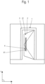
- Figur 1:
- eine schematische Darstellung einer in eine Wand eingebauten Tür mit geöffnetem Flügel;
- Figur 2:
- eine Schnittdarstellung eines ersten Griffprofils mit einer Griffmulde und daran angrenzenden, nur abschnittsweise dargestellten, Türelementen
- Figur 3:
- eine perspektivische Ansicht eines zweiten Griffprofils mit einer Griffmulde;
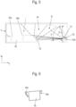
- Figur 4, 5:
- jeweils Schnittdarstellungen eines dritten Griffprofils mit einer Griffmulde;
- Figur 6:
- eine Seitenansicht eines Gehäuses eines Fingerscanners;
- Figur 7:
- in a) bis e) jeweils eine Schnittdarstellung einer Ausführungsvariante des Griffprofils.
- Die im Folgenden verwendeten Begriffe wie "oben", "unten", "rechts", "links", "seitlich", vertikal", "horizontal" beziehen sich auf die jeweilige Zeichnungsebene.
- Die
Fig. 1 zeigt eine Tür 1, die einen Flügel 2, insbesondere mit einem Flügelrahmen (hier nicht dargestellt), und vorzugsweise mit wenigstens einem Flächenelement 21, und einen - vorzugsweise an einer Seite offenen oder umfangsgeschlossenen - Blendrahmen 3 aufweist. Dies ist lediglich rein beispielhaft zu verstehen. Alternativ zu der inFig. 1 dargestellten Tür 1 kann die vorliegende Erfindung auch bei Fenstern oder dgl. eingesetzt werden. Sofern nachfolgend der Begriff "Tür" verwendet wird, kann er daher auch durch den Begriff Fenster ersetzt werden. Zudem sind die nachfolgenden Ausgestaltungen auch bei Fassadenelementen anderer Art einsetzbar, so dass der Begriff der "Tür" auch durch den Begriff "Fassadenelement" ersetzt werden kann. Die Tür 1 ist insbesondere zum Einsetzen in eine Gebäudeöffnung ausgelegt. - Der Flügel 2 weist eine Griffanordnung auf. Diese Griffanordnung ist hier als ein Griffprofil 4 mit einer Griffmulde 41 ausgebildet. Die Griffmulde 41 könnte theoretisch auch in einem nicht als Griffprofil 4 ausgebildeten Element ausgebildet sein. Wesentlich ist insofern, dass die Griffanordnung eine Griffmulde 41 aufweist, in welche ein Nutzer eingreifen kann und die dazu einen hinterschnittenen Bereich 45 aufweist. Der Nutzer kann in die Griffmulde 41 derart mit einem oder mehreren Fingern (aber in der Regel nicht mit dem Daumen) eingreifen.
- Das Griffprofil 4 kann in verschiedenster Weise in den Flügel 2 integriert sein, so beispielsweise klebend und/oder schraubend und/oder rastend. Der Flügel 3 kann ansonsten ebenfalls aus verschiedensten Elementen bestehen. So kann er insbesondere einen Flügelrahmen aufweisen und eines oder mehrere Flächenelemente und/oder eines oder mehrere Wärmedämmelemente. Das Griffprofil 4 kann ein- oder mehrteilig ausgebildet sein. Mehrteilige Ausführungsvarianten des Griffprofils 4 sind in den
Figuren 7a bis 7e dargestellt. - Nachfolgend werden vorteilhafte Merkmale jeweils anhand von Ausführungsbeispielen erläutert. Sie können aber auch einzeln oder in Kombination bei anderen Ausführungsbeispiel genutzt werden.
- Im Rahmen der vorliegenden Anmeldung ist die Griffmulde 4 von besonderem Interesse. Im Rahmen dieser Anmeldung ist sie stets eine hinterschnittene Griffmulde 41, d.h. eine Griffmulde 41 mit wenigstens einem hinterschnittenen Bereich.
- Diese Griffmulde 41 ist derart ausgestaltet, dass in sie einer oder mehrere Finger einer Hand eingesteckt werden können, um den Flügel 2 von Hand hier drehend zu öffnen oder zu schließen.
- Die Erstreckung der Griffmulde 41 kann innerhalb des Griffprofils 4 im Wesentlichen bogenförmig sein. Dieser Begriff ist wiederum nicht zu eng auszulegen. Die Bogenform kann durch einen oder mehrere bogenförmige Wandabschnitte realisiert werden. Sie kann aber auch durch mehrere lineare Wandabschnitte oder aus geraden und gebogenen Wandabschnitten angenähert sein.
- Die Griffmulde 41 erstreckt sich - siehe
Fig. 2 - von einem Eintritts- bzw-. Öffnungsbereich 42 entlang einer Frontwand 43 in etwa in einem Bogen 44 in das Griffprofil 4 hinein und endet in einem Hinterschnittbereich 45 hinter einem Frontsteg 46. Dieser Frontsteg 46 hat eine freie Kante bzw. ein freies Ende und deckt den Hinterschnittbereich 45 nach außen hin ab. Er liegt vorzugsweise in der X-/Z-Ebene oder leicht schräg dazu. - In einem Bezugszeichensystem ist die Ebene des Flügels die X-Y-Ebene. In
Fig. 2 ist die dazu senkrechte Querschnittskontur der Griffmulde 41 zu erkennen. In Z-Richtung kann sich die Griffmulde 41 über einen Teil des Griffprofils 4 erstrecken. Sie ist zumindest so lang, dass einer oder mehrere Finger in sie eingesteckt werden können. Sie kann in X-Richtung aber auch länger ausgebildet sein. - Die Griffmulde 41 weist ferner eine Rückwand 47 aus. Diese hat ebenfalls einen in etwa bogenförmigen Verlauf und erstreckt sich bis in den Hinterschnittbereich 45. Dieser Hinterschnittbereich 45 ist von außen zumindest teilweise nicht sichtbar.
- Die Sichtbarkeit hängt von der Blickrichtung einer Person, insbesondere des Nutzers, ab. Eine frontale Blickrichtung im Sinne dieser Schrift ist eine Blickrichtung in Richtung Z senkrecht zur Hauptebene X/Y des Flügels 3 etwa in Höhe eines Gesichtes eines stehenden Nutzers.
- Sieht eine Nutzer in dieser Blickrichtung frontal auf den Flügel im Bereich des Frontsteges 46, sieht er den in Z-Richtung hinter dem Frontsteg 46 liegenden Bereich nicht (hier beispielhaft links der sich in Z-Richtung erstreckenden gestrichelten Linie). Dieser nicht sichtbare Bereich ist hier auch der (ggf. erste) Hinterschnittbereich 45.
- Selbst wenn ein Benutzer schräg (also in
Fig. 2 "schräg von rechts") in die Griffmulde 41 hineinsieht, kann er einen Bereich 45' zwischen der schrägen gestrichelten Linie und dem Frontsteg 46 nicht sehen. Dies ist der in keinem Fall einsichtige bzw. in keinem Fall sichtbare Bereich 45'. - Die Griffmulde 41 ist mit einem Fingerscanner 48 versehen.
- Der Fingerscanner 48 kann im Hinterschnittbereich 45 der Griffmulde 41 angeordnet sein. Derart liegt er gut geschützt und auf den ersten Blick nicht sichtbar in der Griffmulde 41.
- Der Fingerscanner 48 kann dabei besonders bevorzugt im nicht sichtbaren Hinterschnittbereich 45' der Griffmulde 41 angeordnet sein. Derart liegt er quasi von außen unsichtbar in der Griffmulde 41.
- Dies hat den Vorteil, dass Passanten nicht quasi "dazu eingeladen" werden, den Fingerscanner testweise zu berühren. Zudem ist der Fingerscanner 48 gegen Umwelteinflüsse gut geschützt.
- Dabei ist es bevorzugt, wenn der Fingerscanner so in der Griffmulde 41 angeordnet ist, dass er ganz oder zumindest seine eigentliche Scanneroberfläche zum Auflegen eines oder mehrerer Finger, welche das Bild des jeweiligen Fingerbereichs erfasst, relativ zur Frontblickrichtung Z zwischen 135° und 225° (im Uhrzeigersinn betrachtet) gedreht liegt, insbesondere zwischen 150° und 210° gedreht und besonders bevorzugt zwischen 165° und 195° gedreht liegt, insbesondere um 180° gedreht liegt. Der Fingerscanner 48 kann dazu vorzugsweise an der - in Blickrichtung betrachtet - "Rückseite" des Frontsteges 49 angeordnet sein.
- Dies hat den Vorteil, dass die Finger des Nutzers sehr einfach beim Eingreifen in die Griffmulde 41 den Fingerscanner 48 berühren können, denn sie sind bei dem Eingreifen in die Griffmulde 41 quasi automatisch in diese Richtung/Stellung gedreht. So würde ein Nutzer in die in
Fig.2 dargestellte Griffmulde 41 mit einem oder mehreren Fingern der rechten Hand eingreifen. Dann kann wenigstens eine Fingerkuppe auf den Fingerscanner 48 gelegt werden und das zur Zugangskontrolle nötige Bild erfasst werden. Dabei findet der Nutzer bei einem Tasten intuitiv und schnell den Fingerscanner 48. - Nachfolgend werden weitere vorteilhafte Optionen zur Weiterbildung der Erfindung beschrieben.
- Dazu sei auf die
Figuren 2 und die weiterenFiguren 3 bis 6 verwiesen. - Der Frontsteg 46 kann zur Aufnahme des Fingerscanners 48 eine Aufnahmenut 49, insbesondere eine hinterschnittene Aufnahmenut 49 aufweisen.
- Der Fingerscanner 48 kann derart auf einfache Weise mit einem Befestigungsmittel in der Aufnahmenut 49 montiert werden. Dieses Befestigungsmittel kann auf verschiedenste Weise ausgebildet sein.
- Besonders bevorzugt ist vorgesehen, dass der Fingerscanner rastend in der hinterschnitten ausgebildeten Aufnahmenut montiert wird. Dazu weisen er und die Aufnahmenut 49 jeweils eines oder mehrere korrespondierende Befestigungsmittel, insbesondere Rastmittel 48a, b, 49a, b, auf.
- Der Fingerscanner 48 kann in einem besonders montagefreundlichen Gehäuse angeordnet sein. Dieses Gehäuse weist dann die eigentlichen Befestigungsmittel zur Montage in der Montagenut 49 aufweisen. Diese können die erwähnten Rastmittel sein oder Befestigungsmittel zum schwenkenden Einsetzen in die Aufnahmenut.
- Der Frontsteg 46 weist dazu eine entsprechend weite Erstreckung in Z-Richtung auf. Derart kann der Fingerscanner vorzugsweise bündig oder weitestgehend bündig mit der Innenfläche des Frontstegs 46 fluchten/abschließen.
- Die Auslegung kann dabei auch derart sein, dass der Fingerscanner 48 schwenkend in die Aufnahmenut 49 einsetzbar und dort festlegbar ist. Weiter vorzugweise verrastet er dann beim Einschwenken in die Aufnahmenut 49. Derart ist der Fingerscanner besonders einfach in dem hinterschnittenen Bereich 45 montierbar. Vorzugsweise kann er ferner auch leicht demontiert werden, z.B. wenn die Verrastung manuell lösbar ist, z.B. durch Kippen des Fingerscanners 48 oder ziehend an einem Band an einem Rastmittel oder Eindrücken eines Rastmittels mit einem Steg.
- Vorzugsweise kann dieser Fingerscanner 48 werkzeuglos in dem Griffprofil 4 in der Griffmulde 4 montiert werden. Insbesondere bei Vorsehen einer einseitig hinterschnittenen Aufnahmenut 49 ist die vertikale Höhe besonders leicht frei wählbar und auch nachträglich leicht zu ändern. Das Gehäuse des Fingerscanners weist dann vorzugsweise einen Steg auf, der in eine randseitige kleine Einsetznut der Aufnahmenut eingreift. Gegenüberliegend befinden sich dann vorzugsweise einer oder zwei Rastlaschen/-stege, die rastend unter einen Profilsteg der Aufnahmenut 49 greifen.
- Der Fingerscanner 48 kann in der Aufnahmenut 49 quasi in beliebiger Höhe installiert werden und ggf. auch auf eine andere Höhe versetzt werden, wenn dies gewünscht ist.
- Optional kann die Aufnahmenut 49 seitlich bzw. vorzugsweise "über und unter dem Fingerscanner" mit einem Abdeckprofil z.B. aus Kunststoff geschlossen sein, so dass sie nicht verschmutzen kann.
- Der Fingerscanner liegt dabei bevorzugt in X-Richtung in einer Eingrifftiefe von 45-60 mm hinter der freien Kante des Frontsteges 46.
- Der Bedienkomfort von Gebäudeöffnungen, wie beispielsweise Haustüren, wird durch den solchen Fingerscanner 48 erhöht. Das Öffnen des Flügels 2 kann vorteilhaft in einer fließenden Bewegung erfolgen. Das Berühren des Fingerscanners 48 und das Öffnen des Flügels 2 können direkt ineinander übergehen.
- Optional kann vorgesehen sein, das Griffprofil 4 mit wenigstens einem Leuchtmittel 50 zu versehen.
- Dabei kann das Leuchtmittel 50 derart vorzugsweise angeordnet und ausgerichtet sein, dass es die Griffmulde 41 ganz oder teilweise ausleuchtet.
- Das Leuchtmittel 50 kann durch eine oder mehrere LEDs gebildet werden oder eine oder mehrere solche aufweisen.
- Diese LEDs können nach einer Variante in den Fingerscanner 48 bzw. ein Gehäuse des Fingerscanners 48 integriert sein.
- Vorzugsweise spiegelt sich das Licht des Leuchtmittels 50 so in der Griffmulde 41, dass der Nutzer die Position wahrnimmt bzw. in dem Licht einen Hinweis auf die Position des Fingerscanners 48 sieht.
- Das Leuchtmittel 50 kann vorzugsweise in einem zweiten Hinterschnittbereich 51 montiert sein, welcher auf der gegenüberliegenden anderen Seite des Öffnungsbereiches 42 der Griffmulde 41 ausgebildet ist, also in einem anderen Hinterschnittbereich als der Fingerscanner 48.
- Es kann weiter vorteilhaft vorgesehen sein, den Frontsteg 46 an seiner Innenseite zum freien Ende hin abgerundet auszubilden. Dieser abgerundete Bereich 52 wird dann vorzugsweise von dem Leuchtmittel 50 angeleuchtet bzw. beleuchtet, so dass sich das Licht von dem inneren abgerundeten Bereich in den Bereich der abgerundeten Rückwand 47 der Griffmulde 41 reflektiert wird. Dies sorgt für eine besonders harmonische Ausleuchtung der Griffmulde 41. Dabei kann das Leuchtmittel 50 derart vorzugsweise angeordnet und ausgerichtet sein, dass es die Griffmulde 41 ganz oder teilweise ausleuchtet. Das Leuchtmittel 50, insbesondere die eine LED oder die mehreren LEDs, ist/sind dabei vorzugweise auch so angeordnet, dass sie nicht direkt von außen sichtbar ist/sind.
- Die vorteilhafte Ausleuchtung der Griffmulde 41 ist eine vorteilhafte Weiterbildung in Kombination mit einem bzw. dem Fingerscanner 48. Sie ist aber auch ohne einen Fingerscanner vorteilhaft einsetzbar.
- Vorteilhaft ist insofern besonders, wenn das Leuchtmittel 50b in dem zweiten Hinterschnittbereich 51 angeordnet ist -wie dies in
Fig. 5 gezeigt ist- und schräg sein Licht in Richtung des anderen Hinterschnittbereiches 45 abstrahlt. Vorzugsweise liegt der Abstrahlwinkel α bei 60° ±15° zur Blickrichtung Z. Das Leuchtmittel sollte dann sein Licht in einem Leuchtwinkel β von ca. 120° ± 30° abstrahlen, also insbesondere den Öffnungsbereich 42 ausleuchten sowie auch in den ersten hinterschnittenen Bereich 45 hinein leuchten. Dabei kann auch ein Teil des Lichtes von der abgerundeten Bereich 46 innen am freien Ende des Frontstege reflektiert werden. Es wird derart eine Positionierung der LED tangential in dem Kreisbogen der Rückwand 47 der Griffmulde 41 zur harmonischen Ausleuchtung realisiert. Der Kreisbogen erzeugt einen optimalen Abstrahleffekt, wodurch die Ausleuchtung der Griffmulde 41 optimal erscheint. Derart wird z.B. in der Regel auch ein Schattenwurf infolge eines Handeingriffs vermieden. Die LEDs leuchten über den Handrücken hinweg. - Es kann weiter bevorzugt vorgesehen sein, dass LED-Licht hinsichtlich der Farbtemperatur (z.B. zwischen 2400-6500K) steuerbar ist und auch hinsichtlich der Helligkeit (dimmbar) steuerbar ist.
- Das dargestellte Griffprofil 41 ist montiert, um von einer rechten Hand eines Nutzers gegriffen zu werden. Eine Montage an einem anderen Ort in anderer Ausrichtung ist ebenfalls denkbar.
- In
Fig. 7a bis Fig. 7e sind jeweils Ausführungsvarianten des Griffprofils 4 dargestellt. Die hier dargestellten Griffprofile 4 sind jeweils aus zwei Teilprofilen, hier einem bezogen auf die Blickrichtung ersten, hinteren Teilprofil 4a und einem zweiten, vorderen Teilprofil 4b zusammengesetzt. Eine solche Aufteilung des Griffprofils 4 in zwei Teilprofile 4a, 4b hat eine Reihe von Vorteilen. - Wesentlicher Vorteil ist eine einfachere Fertigung in einem Strangpressprozess, da der Querschnitt des jeweiligen Teilprofils 4a, 4b kleiner ist als der Querschnitt des Griffprofils 4. Ferner sind die Teilprofile 4a, 4b jeweils geschlossene Profile ohne Hinterschnitt. Beides führt dazu, dass die Teilprofile 4a, 4b einfacher durch einen Strangpressprozess herstellbar sind als das offene, einstückige Griffprofil 4 mit Hinterschnitt.
- Weiterhin ist ein Beschichtungsvorgang, wie z.B. ein Lackierprozess bei zwei Teilprofilen 4a, 4b einfacher durchführbar. Dies gilt insbesondere für einen Pulverlackierprozess, bei dem der Pulverlack oder die zu lackierenden Teile elektrostatisch aufgeladen ist / sind. Bei einem einstückigen Griffprofil 4 bildet die Griffmulde 41 einen Faraday'schen Käfig, in dem sich nur schwierig Pulverlack niederschlagen kann, so dass diese Bereiche in einen aufwändigen Prozess nachgearbeitet werden müssen.
- Die Teilprofile 4a, 4b sind jeweils in einem Eckbereich 53 des Griffprofils 4 im nicht sichtbaren Hinterschnittbereich 45' zusammengefügt.
- In
Fig. 7a sind die beiden Teilprofile 4a, 4b durch zwei pilz- oder kederartige Rastmittel 54a, b formschlüssig zusammengefügt. Die beiden Rastmittel 54a, b sind an dem ersten Teilprofil 4a einstückig angeformt und greifen in zwei geometrisch korrespondierende Nuten 55a, b ein. In die Nuten 55a, b sind zwei Dichtprofile 56a, b eingelegt. Ein Formschluss wird hier zwischen den Rastmitteln 54a, b und den Dichtprofilen 56a, b durch eine Verformung der Dichtprofile 56a, b hergestellt. Dadurch können die beiden Teilprofile 4a, b einfach miteinander montiert bzw. verbunden werden. - In
Fig. 7b sind die beiden Teilprofile 4a, b durch zwei Rastmittel 54a, b mit einem hakenartigen Querschnitt verbunden, die einstückig an das erste, hintere Teilprofil 4a angeformt sind. Die beiden Rastmittel 54a, b greifen in eine gemeinsame Nut 57 ein, die durch das zweite, vordere Teilprofil 4b ausgeformt wird. Durch ein Dichtprofil 58, das als Rundschnurdichtung gestaltet sein kann, wird durch die Verformung des Dichtprofils 58 ein spielfreier Formschluss zwischen den beiden Teilprofilen 4a, b erreicht. - In
Fig 7c sind die beiden Teilprofile 4a, b durch zwei schnapphakenartige Rastmittel 54a, b formschlüssig miteinander verbunden. Die Rastmittel 54a, b sind einstückig an dem zweiten vorderen Teilprofil 4b angeformt und greifen in eine gemeinsame Nut 57 ein, die das erste hintere Teilprofil 4b ausformt. - In
Fig. 7d sind die beiden Teilprofile 4a, b durch zwei kederartige Verbindungsmittel 59a, b zusammengefügt, die an das zweite, vordere Teilprofil 4b einstückig angeformt sind und die in jeweils eine geometrisch korrespondierende Nut 60a, b eingreifen, die das erste hintere Teilprofil 4a ausformt. Zu Herstellen einer formschlüssigen Verbindung werden die beiden Teilprofile 4a, b ineinander geschoben. - In
Fig. 7e sind die beiden Teilprofile 4a, b durch eine Schraube als Verbindungsmittel 59 miteinander verbunden. Die Schraube ist hier als Senkkopfschraube ausgeführt. Durch die Schraube wird eine kraftschlüssige Verbindung zwischen den beiden Teilprofilen 4a, b hergestellt.Bezugszeichenliste Tür 1 Flügel 2 Flächenelement 21 Blendrahmen 3 Griffprofil 4 Griffmulde 41 Öffnungsbereich 42 Frontwand 43 Bogen 44 Hinterschnittbereich 45 nicht sichtbarer Hinterschnittbereich 45' Frontsteg 46 Rückwand 47 Fingerscanner 48 Aufnahmenut 49 Rastmittel 48a, b, 49a, b Leuchtmittel 50 Hinterschnittbereich 51 abgerundeter Bereich 52 Eckbereich 53 Rastmittel 54a, b Nut 55a, b Dichtprofil 56a, b Nut 57 Dichtprofil 58 Verbindungsmittel 59, 59a, b
Claims (17)
- Fenster-, Tür- oder Fassadenelement, insbesondere Tür für eine Gebäudeöffnung, insbesondere mit einem Blendrahmen (3) und mit einem daran beweglich angeordneten Flügel (2) mit einer Griffanordnung, insbesondere einem Griffprofil, mit einer Griffmulde, dadurch gekennzeichnet, dass die Griffmulde (41) wenigstens einen Fingerscanner (48) aufweist.
- Fenster-, Tür- oder Fassadenelement nach Anspruch 1, dadurch gekennzeichnet. dass die Griffmulde (41) wenigstens einen hinterschnittenen Bereich (45) aufweist, in den ein Nutzer mit einem oder mehreren Fingern oder Fingerkuppen eingreifen kann und dass der Fingerscanner (48) in dem hinterschnittenen Bereich (45) angeordnet ist.
- Fenster-, Tür- oder Fassadenelement nach Anspruch 1 oder 2, dadurch gekennzeichnet, dass der Fingerscanner (48) in einem nicht einsichtigen bzw. sichtbaren Bereich der Griffmulde (41) angeordnet ist, wobei der Fingerscanner (48) in einem in keiner Blickrichtung von außerhalb der Griffmulde (41) einsichtigen bzw. sichtbaren Bereich (45') der Griffmulde (41) angeordnet ist.
- Fenster-, Tür- oder Fassadenelement nach Anspruch 2 oder 3, dadurch gekennzeichnet, dass der Fingerscanner (48) eine Scann-Oberfläche zum Auflegen eines oder mehrerer Finger aufweist, die in der Griffmulde in einem Winkel von 135° bis 225° zur frontalen Blickrichtung (Z) ausgerichtet ist.
- Fenster-, Tür- oder Fassadenelement nach einem der vorstehenden Ansprüche oder nach dem Oberbegriff des Anspruchs 1, dadurch gekennzeichnet, dass wenigstens ein Leuchtmittel (50) in einem hinterschnittenen und vorzugsweise in frontaler Blickrichtung von außerhalb der Griffmulde (41) nicht sichtbaren Bereich der Griffmulde (41) angeordnet ist.
- Fenster-, Tür- oder Fassadenelement nach einem der vorstehenden Ansprüche, dadurch gekennzeichnet, dass sich die Griffmulde (41) von einem Eintritts- bzw.-. Öffnungsbereich (42) in etwa in einem Bogen (44) in das Griffprofil (4) hinein und dass sie in dem Hinterschnittbereich (45) hinter einem Frontsteg (46) mündet, welcher den Hinterschnittbereich (45) nach außen hin abdeckt, insbesondere derart, dass der Fingerscanner (48) an der - in Blickrichtung (Z) betrachtet - Rückseite bzw. Innenseite des Frontsteges (46) angeordnet ist.
- Fenster-, Tür- oder Fassadenelement nach einem der vorstehenden Ansprüche, dadurch gekennzeichnet, dass die Griffmulde (41) ferner eine Rückwand (48) oder Innenwand aufweist, die einen in etwa bogenförmigen Verlauf aufweist und sich bis in den Hinterschnittbereich (45) erstreckt.
- Fenster-, Tür- oder Fassadenelement nach einem der vorstehenden Ansprüche, dadurch gekennzeichnet, dass zur Aufnahme des Fingerscanners (48) eine Aufnahmenut (49) , insbesondere eine hinterschnittene Aufnahmenut 49, insbesondere an der Innenseite des Frontsteges (46) vorgesehen ist.
- Fenster-, Tür- oder Fassadenelement nach einem der vorstehenden Ansprüche, dadurch gekennzeichnet, dass der Fingerscanner (48) mit einem Befestigungsmittel in der Aufnahmenut (49) montiert ist, wobei der Fingerscanner (48) vorzugsweise rastend in der Aufnahmenut (49) montiert ist.
- Fenster-, Tür- oder Fassadenelement nach einem der vorstehenden Ansprüche, dadurch gekennzeichnet, dass der Fingerscanner (48) mit einer Schwenkbewegung in der Aufnahmenut (49) montierbar ist.
- Fenster-, Tür- oder Fassadenelement nach einem der vorstehenden Ansprüche, dadurch gekennzeichnet, dass der Fingerscanner (48) eine ertastbare Oberflächenstrukturierung aufweist und/oder dass der Fingerscanner (48) das Leuchtmittel (50) aufweist.
- Fenster-, Tür- oder Fassadenelement nach einem der vorstehenden Ansprüche, dadurch gekennzeichnet, dass das Leuchtmittel (50) in einem zweiten hinterschnittenen Bereich (51) an der dem Frontsteg (46) gegenüberliegenden Seite des Öffnungsbereiches (42) der Griffmulde (41) angeordnet ist.
- Fenster-, Tür- oder Fassadenelement nach einem der vorstehenden Ansprüche, dadurch gekennzeichnet, dass das Leuchtmittel (50) aus dem zweiten hinterschnittenen Bereich (51) eine abgerundete Innenfläche des Frontsteges (46) anstrahlt, von der Licht zur Rückwand (48) reflektiert wird.
- Fenster-, Tür- oder Fassadenelement nach einem der vorstehenden Ansprüche, dadurch gekennzeichnet, dass das Leuchtmittel (50) aus dem zweiten hinterschnittenen Bereich (51) in einem Winkel von 60° ± 15° zur frontalen Blickrichtung (Z) die abgerundete Innenfläche des Frontsteges (46) beleuchtet.
- Fenster-, Tür- oder Fassadenelement nach einem der vorstehenden Ansprüche, dadurch gekennzeichnet, dass das Griffprofil (4) jeweils aus wenigstens zwei Elementen, insbesondere wenigstens zwei Teilprofilen, zusammengesetzt ist.
- Fenster-, Tür- oder Fassadenelement nach Anspruch 15, dadurch gekennzeichnet, dass das Griffprofil (4) jeweils aus einem ersten, hinteren Teilprofil (4a) und einem zweiten, vorderen Teilprofil (4b) zusammengesetzt ist, vorzugsweise derart, dass die wenigstens zwei Teilprofile (4a, 4b) durch eines oder mehrere korrespondierende Verbindungsmittel form- und/oder kraftschlüssig verbunden sind, wobei die Verbindungsmittel vorzugsweise Rastmittel (54a, b) sind.
- Griffanordnung, insbesondere Griffprofil (4), mit einer Griffmulde (41), für ein Fenster-, Tür- oder Fassadenelement nach einem der vorstehenden Ansprüche, dadurch gekennzeichnet, dass die Griffmulde (41) wenigstens einen Fingerscanner (48) aufweist.
Applications Claiming Priority (1)
| Application Number | Priority Date | Filing Date | Title |
|---|---|---|---|
| DE102021123539.1A DE102021123539A1 (de) | 2021-09-10 | 2021-09-10 | Fenster-, Tür- oder Fassadenelement mit einer Griffanordnung und Griffanordnung |
Publications (2)
| Publication Number | Publication Date |
|---|---|
| EP4148209A1 true EP4148209A1 (de) | 2023-03-15 |
| EP4148209B1 EP4148209B1 (de) | 2024-01-24 |
Family
ID=83080673
Family Applications (1)
| Application Number | Title | Priority Date | Filing Date |
|---|---|---|---|
| EP22192055.6A Active EP4148209B1 (de) | 2021-09-10 | 2022-08-25 | Fenster-, tür- oder fassadenelement mit einer griffanordnung |
Country Status (3)
| Country | Link |
|---|---|
| EP (1) | EP4148209B1 (de) |
| DE (1) | DE102021123539A1 (de) |
| PL (1) | PL4148209T3 (de) |
Citations (6)
| Publication number | Priority date | Publication date | Assignee | Title |
|---|---|---|---|---|
| JPH11315657A (ja) * | 1998-05-06 | 1999-11-16 | Mazda Motor Corp | 車両用ドア解錠装置 |
| JP2003221960A (ja) * | 2002-01-29 | 2003-08-08 | Tokai Rika Co Ltd | ドア開閉装置 |
| DE202008001663U1 (de) | 2008-02-06 | 2009-06-25 | Biffar Gmbh & Co. Kg | Tür, insbesondere Haustür |
| US20140000165A1 (en) * | 2012-06-29 | 2014-01-02 | Ford Global Technologies, Llc | Flush-mounted door handle for vehicles |
| EP3196395A1 (de) | 2014-05-05 | 2017-07-26 | SCHÜCO International KG | Tür mit einem griffprofil |
| CN213683761U (zh) * | 2020-10-27 | 2021-07-13 | 极景门窗有限公司 | 一种新型入户门 |
Family Cites Families (4)
| Publication number | Priority date | Publication date | Assignee | Title |
|---|---|---|---|---|
| CH700048B1 (de) | 2008-12-05 | 2012-04-30 | Feller Ag | Fingerscanner sowie Fingererkennungsanordnung. |
| US20150337571A1 (en) | 2014-04-30 | 2015-11-26 | STRATTEC Advanced Logic | Handle with integrated biometrics and vehicular biometric device |
| US20180361993A1 (en) | 2017-06-14 | 2018-12-20 | Forrester J. Carroll | Biometric Lock System |
| GB2574190A (en) | 2018-04-17 | 2019-12-04 | Tata Motors European Technical Ct Plc | A handle assembly for a vehicle and method |
-
2021
- 2021-09-10 DE DE102021123539.1A patent/DE102021123539A1/de active Pending
-
2022
- 2022-08-25 PL PL22192055.6T patent/PL4148209T3/pl unknown
- 2022-08-25 EP EP22192055.6A patent/EP4148209B1/de active Active
Patent Citations (6)
| Publication number | Priority date | Publication date | Assignee | Title |
|---|---|---|---|---|
| JPH11315657A (ja) * | 1998-05-06 | 1999-11-16 | Mazda Motor Corp | 車両用ドア解錠装置 |
| JP2003221960A (ja) * | 2002-01-29 | 2003-08-08 | Tokai Rika Co Ltd | ドア開閉装置 |
| DE202008001663U1 (de) | 2008-02-06 | 2009-06-25 | Biffar Gmbh & Co. Kg | Tür, insbesondere Haustür |
| US20140000165A1 (en) * | 2012-06-29 | 2014-01-02 | Ford Global Technologies, Llc | Flush-mounted door handle for vehicles |
| EP3196395A1 (de) | 2014-05-05 | 2017-07-26 | SCHÜCO International KG | Tür mit einem griffprofil |
| CN213683761U (zh) * | 2020-10-27 | 2021-07-13 | 极景门窗有限公司 | 一种新型入户门 |
Also Published As
| Publication number | Publication date |
|---|---|
| EP4148209B1 (de) | 2024-01-24 |
| PL4148209T3 (pl) | 2024-06-24 |
| DE102021123539A1 (de) | 2023-03-16 |
Similar Documents
| Publication | Publication Date | Title |
|---|---|---|
| DE102005048693B4 (de) | Türöffneranordnung sowie Adapterstück zur Verwendung in einer Türöffneranordnung | |
| EP1085153A2 (de) | Verriegelbares Dreh- und/oder Schiebeflügelsystem | |
| DE19801721C1 (de) | Schubstangenverschluß | |
| AT520765A1 (de) | Schubladenseitenwand mit einem Abdeckprofil | |
| EP1283934B1 (de) | Kraftfahrzeug-türschliesssystem mit schnellentriegelung | |
| EP2796645B1 (de) | Riegelschloss eines Möbels | |
| EP4148209B1 (de) | Fenster-, tür- oder fassadenelement mit einer griffanordnung | |
| DE3630406C2 (de) | ||
| CH700048A1 (de) | Fingerscanner sowie Fingererkennungsanordnung. | |
| DE3621592C1 (en) | Locking system on a motor vehicle | |
| EP2697460B1 (de) | Flügelanlage | |
| EP3689187B1 (de) | Schrankmöbel | |
| DE102020122859A1 (de) | Fenster | |
| DE202006018635U1 (de) | Vertikal adaptierter Türdrücker | |
| EP2238661B1 (de) | Vandalismussicherer schrank | |
| DE102005020729B3 (de) | In einer Tür oder in einer Klappe integrierte Betätigungs- und Verschluss- oder Verriegelungseinheit | |
| AT509205B1 (de) | Paniktür | |
| DE29621348U1 (de) | Verriegelungsvorrichtung für Fenster und Türen | |
| DE29611822U1 (de) | Schloß mit Gleitfalle | |
| DE202008007982U1 (de) | Blendleistenanordnung | |
| DE19547255C1 (de) | Zusatzverriegelung | |
| DE202024002314U1 (de) | Vorrichtung zum Sperren von Fenstern, Balkon- und Terrassentüren | |
| DE29823344U1 (de) | Schubstangenverschluß | |
| DE20205886U1 (de) | Türschloss | |
| CH717978A2 (de) | Vorrichtung zur hygienischen Betätigung einer Tür und Tür. |
Legal Events
| Date | Code | Title | Description |
|---|---|---|---|
| PUAI | Public reference made under article 153(3) epc to a published international application that has entered the european phase |
Free format text: ORIGINAL CODE: 0009012 |
|
| STAA | Information on the status of an ep patent application or granted ep patent |
Free format text: STATUS: THE APPLICATION HAS BEEN PUBLISHED |
|
| AK | Designated contracting states |
Kind code of ref document: A1 Designated state(s): AL AT BE BG CH CY CZ DE DK EE ES FI FR GB GR HR HU IE IS IT LI LT LU LV MC MK MT NL NO PL PT RO RS SE SI SK SM TR |
|
| STAA | Information on the status of an ep patent application or granted ep patent |
Free format text: STATUS: REQUEST FOR EXAMINATION WAS MADE |
|
| 17P | Request for examination filed |
Effective date: 20230718 |
|
| RBV | Designated contracting states (corrected) |
Designated state(s): AL AT BE BG CH CY CZ DE DK EE ES FI FR GB GR HR HU IE IS IT LI LT LU LV MC MK MT NL NO PL PT RO RS SE SI SK SM TR |
|
| GRAP | Despatch of communication of intention to grant a patent |
Free format text: ORIGINAL CODE: EPIDOSNIGR1 |
|
| STAA | Information on the status of an ep patent application or granted ep patent |
Free format text: STATUS: GRANT OF PATENT IS INTENDED |
|
| INTG | Intention to grant announced |
Effective date: 20231013 |
|
| GRAS | Grant fee paid |
Free format text: ORIGINAL CODE: EPIDOSNIGR3 |
|
| P01 | Opt-out of the competence of the unified patent court (upc) registered |
Effective date: 20231031 |
|
| GRAA | (expected) grant |
Free format text: ORIGINAL CODE: 0009210 |
|
| STAA | Information on the status of an ep patent application or granted ep patent |
Free format text: STATUS: THE PATENT HAS BEEN GRANTED |
|
| AK | Designated contracting states |
Kind code of ref document: B1 Designated state(s): AL AT BE BG CH CY CZ DE DK EE ES FI FR GB GR HR HU IE IS IT LI LT LU LV MC MK MT NL NO PL PT RO RS SE SI SK SM TR |
|
| REG | Reference to a national code |
Ref country code: GB Ref legal event code: FG4D Free format text: NOT ENGLISH |
|
| REG | Reference to a national code |
Ref country code: CH Ref legal event code: EP |
|
| REG | Reference to a national code |
Ref country code: DE Ref legal event code: R096 Ref document number: 502022000425 Country of ref document: DE |
|
| REG | Reference to a national code |
Ref country code: IE Ref legal event code: FG4D Free format text: LANGUAGE OF EP DOCUMENT: GERMAN |
|
| REG | Reference to a national code |
Ref country code: SE Ref legal event code: TRGR |
|
| REG | Reference to a national code |
Ref country code: NL Ref legal event code: FP |
|
| REG | Reference to a national code |
Ref country code: LT Ref legal event code: MG9D |
|
| PG25 | Lapsed in a contracting state [announced via postgrant information from national office to epo] |
Ref country code: IS Free format text: LAPSE BECAUSE OF FAILURE TO SUBMIT A TRANSLATION OF THE DESCRIPTION OR TO PAY THE FEE WITHIN THE PRESCRIBED TIME-LIMIT Effective date: 20240524 |
|
| PG25 | Lapsed in a contracting state [announced via postgrant information from national office to epo] |
Ref country code: LT Free format text: LAPSE BECAUSE OF FAILURE TO SUBMIT A TRANSLATION OF THE DESCRIPTION OR TO PAY THE FEE WITHIN THE PRESCRIBED TIME-LIMIT Effective date: 20240124 |
|
| PG25 | Lapsed in a contracting state [announced via postgrant information from national office to epo] |
Ref country code: GR Free format text: LAPSE BECAUSE OF FAILURE TO SUBMIT A TRANSLATION OF THE DESCRIPTION OR TO PAY THE FEE WITHIN THE PRESCRIBED TIME-LIMIT Effective date: 20240425 |
|
| PG25 | Lapsed in a contracting state [announced via postgrant information from national office to epo] |
Ref country code: HR Free format text: LAPSE BECAUSE OF FAILURE TO SUBMIT A TRANSLATION OF THE DESCRIPTION OR TO PAY THE FEE WITHIN THE PRESCRIBED TIME-LIMIT Effective date: 20240124 Ref country code: RS Free format text: LAPSE BECAUSE OF FAILURE TO SUBMIT A TRANSLATION OF THE DESCRIPTION OR TO PAY THE FEE WITHIN THE PRESCRIBED TIME-LIMIT Effective date: 20240424 |
|
| PG25 | Lapsed in a contracting state [announced via postgrant information from national office to epo] |
Ref country code: ES Free format text: LAPSE BECAUSE OF FAILURE TO SUBMIT A TRANSLATION OF THE DESCRIPTION OR TO PAY THE FEE WITHIN THE PRESCRIBED TIME-LIMIT Effective date: 20240124 |
|
| PG25 | Lapsed in a contracting state [announced via postgrant information from national office to epo] |
Ref country code: RS Free format text: LAPSE BECAUSE OF FAILURE TO SUBMIT A TRANSLATION OF THE DESCRIPTION OR TO PAY THE FEE WITHIN THE PRESCRIBED TIME-LIMIT Effective date: 20240424 Ref country code: LT Free format text: LAPSE BECAUSE OF FAILURE TO SUBMIT A TRANSLATION OF THE DESCRIPTION OR TO PAY THE FEE WITHIN THE PRESCRIBED TIME-LIMIT Effective date: 20240124 Ref country code: IS Free format text: LAPSE BECAUSE OF FAILURE TO SUBMIT A TRANSLATION OF THE DESCRIPTION OR TO PAY THE FEE WITHIN THE PRESCRIBED TIME-LIMIT Effective date: 20240524 Ref country code: HR Free format text: LAPSE BECAUSE OF FAILURE TO SUBMIT A TRANSLATION OF THE DESCRIPTION OR TO PAY THE FEE WITHIN THE PRESCRIBED TIME-LIMIT Effective date: 20240124 Ref country code: GR Free format text: LAPSE BECAUSE OF FAILURE TO SUBMIT A TRANSLATION OF THE DESCRIPTION OR TO PAY THE FEE WITHIN THE PRESCRIBED TIME-LIMIT Effective date: 20240425 Ref country code: FI Free format text: LAPSE BECAUSE OF FAILURE TO SUBMIT A TRANSLATION OF THE DESCRIPTION OR TO PAY THE FEE WITHIN THE PRESCRIBED TIME-LIMIT Effective date: 20240124 Ref country code: ES Free format text: LAPSE BECAUSE OF FAILURE TO SUBMIT A TRANSLATION OF THE DESCRIPTION OR TO PAY THE FEE WITHIN THE PRESCRIBED TIME-LIMIT Effective date: 20240124 Ref country code: BG Free format text: LAPSE BECAUSE OF FAILURE TO SUBMIT A TRANSLATION OF THE DESCRIPTION OR TO PAY THE FEE WITHIN THE PRESCRIBED TIME-LIMIT Effective date: 20240124 |
|
| PG25 | Lapsed in a contracting state [announced via postgrant information from national office to epo] |
Ref country code: PT Free format text: LAPSE BECAUSE OF FAILURE TO SUBMIT A TRANSLATION OF THE DESCRIPTION OR TO PAY THE FEE WITHIN THE PRESCRIBED TIME-LIMIT Effective date: 20240524 |
|
| PG25 | Lapsed in a contracting state [announced via postgrant information from national office to epo] |
Ref country code: PT Free format text: LAPSE BECAUSE OF FAILURE TO SUBMIT A TRANSLATION OF THE DESCRIPTION OR TO PAY THE FEE WITHIN THE PRESCRIBED TIME-LIMIT Effective date: 20240524 Ref country code: LV Free format text: LAPSE BECAUSE OF FAILURE TO SUBMIT A TRANSLATION OF THE DESCRIPTION OR TO PAY THE FEE WITHIN THE PRESCRIBED TIME-LIMIT Effective date: 20240124 |
|
| PG25 | Lapsed in a contracting state [announced via postgrant information from national office to epo] |
Ref country code: DK Free format text: LAPSE BECAUSE OF FAILURE TO SUBMIT A TRANSLATION OF THE DESCRIPTION OR TO PAY THE FEE WITHIN THE PRESCRIBED TIME-LIMIT Effective date: 20240124 |
|
| PG25 | Lapsed in a contracting state [announced via postgrant information from national office to epo] |
Ref country code: SM Free format text: LAPSE BECAUSE OF FAILURE TO SUBMIT A TRANSLATION OF THE DESCRIPTION OR TO PAY THE FEE WITHIN THE PRESCRIBED TIME-LIMIT Effective date: 20240124 |
|
| PG25 | Lapsed in a contracting state [announced via postgrant information from national office to epo] |
Ref country code: CZ Free format text: LAPSE BECAUSE OF FAILURE TO SUBMIT A TRANSLATION OF THE DESCRIPTION OR TO PAY THE FEE WITHIN THE PRESCRIBED TIME-LIMIT Effective date: 20240124 Ref country code: EE Free format text: LAPSE BECAUSE OF FAILURE TO SUBMIT A TRANSLATION OF THE DESCRIPTION OR TO PAY THE FEE WITHIN THE PRESCRIBED TIME-LIMIT Effective date: 20240124 |
|
| REG | Reference to a national code |
Ref country code: DE Ref legal event code: R097 Ref document number: 502022000425 Country of ref document: DE |
|
| PG25 | Lapsed in a contracting state [announced via postgrant information from national office to epo] |
Ref country code: SK Free format text: LAPSE BECAUSE OF FAILURE TO SUBMIT A TRANSLATION OF THE DESCRIPTION OR TO PAY THE FEE WITHIN THE PRESCRIBED TIME-LIMIT Effective date: 20240124 |
|
| PG25 | Lapsed in a contracting state [announced via postgrant information from national office to epo] |
Ref country code: SM Free format text: LAPSE BECAUSE OF FAILURE TO SUBMIT A TRANSLATION OF THE DESCRIPTION OR TO PAY THE FEE WITHIN THE PRESCRIBED TIME-LIMIT Effective date: 20240124 Ref country code: SK Free format text: LAPSE BECAUSE OF FAILURE TO SUBMIT A TRANSLATION OF THE DESCRIPTION OR TO PAY THE FEE WITHIN THE PRESCRIBED TIME-LIMIT Effective date: 20240124 Ref country code: EE Free format text: LAPSE BECAUSE OF FAILURE TO SUBMIT A TRANSLATION OF THE DESCRIPTION OR TO PAY THE FEE WITHIN THE PRESCRIBED TIME-LIMIT Effective date: 20240124 Ref country code: DK Free format text: LAPSE BECAUSE OF FAILURE TO SUBMIT A TRANSLATION OF THE DESCRIPTION OR TO PAY THE FEE WITHIN THE PRESCRIBED TIME-LIMIT Effective date: 20240124 Ref country code: CZ Free format text: LAPSE BECAUSE OF FAILURE TO SUBMIT A TRANSLATION OF THE DESCRIPTION OR TO PAY THE FEE WITHIN THE PRESCRIBED TIME-LIMIT Effective date: 20240124 |
|
| PLBE | No opposition filed within time limit |
Free format text: ORIGINAL CODE: 0009261 |
|
| STAA | Information on the status of an ep patent application or granted ep patent |
Free format text: STATUS: NO OPPOSITION FILED WITHIN TIME LIMIT |
|
| 26N | No opposition filed |
Effective date: 20241025 |
|
| PG25 | Lapsed in a contracting state [announced via postgrant information from national office to epo] |
Ref country code: LU Free format text: LAPSE BECAUSE OF NON-PAYMENT OF DUE FEES Effective date: 20240825 |
|
| PG25 | Lapsed in a contracting state [announced via postgrant information from national office to epo] |
Ref country code: MC Free format text: LAPSE BECAUSE OF FAILURE TO SUBMIT A TRANSLATION OF THE DESCRIPTION OR TO PAY THE FEE WITHIN THE PRESCRIBED TIME-LIMIT Effective date: 20240124 Ref country code: SI Free format text: LAPSE BECAUSE OF FAILURE TO SUBMIT A TRANSLATION OF THE DESCRIPTION OR TO PAY THE FEE WITHIN THE PRESCRIBED TIME-LIMIT Effective date: 20240124 |
|
| PG25 | Lapsed in a contracting state [announced via postgrant information from national office to epo] |
Ref country code: IE Free format text: LAPSE BECAUSE OF NON-PAYMENT OF DUE FEES Effective date: 20240825 |
|
| PGFP | Annual fee paid to national office [announced via postgrant information from national office to epo] |
Ref country code: NL Payment date: 20250801 Year of fee payment: 4 |
|
| PGFP | Annual fee paid to national office [announced via postgrant information from national office to epo] |
Ref country code: DE Payment date: 20250801 Year of fee payment: 4 |
|
| PGFP | Annual fee paid to national office [announced via postgrant information from national office to epo] |
Ref country code: NO Payment date: 20250801 Year of fee payment: 4 |
|
| PGFP | Annual fee paid to national office [announced via postgrant information from national office to epo] |
Ref country code: PL Payment date: 20250801 Year of fee payment: 4 Ref country code: IT Payment date: 20250901 Year of fee payment: 4 |
|
| PGFP | Annual fee paid to national office [announced via postgrant information from national office to epo] |
Ref country code: BE Payment date: 20250801 Year of fee payment: 4 |
|
| PGFP | Annual fee paid to national office [announced via postgrant information from national office to epo] |
Ref country code: FR Payment date: 20250731 Year of fee payment: 4 Ref country code: AT Payment date: 20251020 Year of fee payment: 4 |
|
| PGFP | Annual fee paid to national office [announced via postgrant information from national office to epo] |
Ref country code: CH Payment date: 20250901 Year of fee payment: 4 Ref country code: SE Payment date: 20250801 Year of fee payment: 4 |
|
| PG25 | Lapsed in a contracting state [announced via postgrant information from national office to epo] |
Ref country code: RO Free format text: LAPSE BECAUSE OF FAILURE TO SUBMIT A TRANSLATION OF THE DESCRIPTION OR TO PAY THE FEE WITHIN THE PRESCRIBED TIME-LIMIT Effective date: 20240124 |
|
| PG25 | Lapsed in a contracting state [announced via postgrant information from national office to epo] |
Ref country code: CY Free format text: LAPSE BECAUSE OF FAILURE TO SUBMIT A TRANSLATION OF THE DESCRIPTION OR TO PAY THE FEE WITHIN THE PRESCRIBED TIME-LIMIT; INVALID AB INITIO Effective date: 20220825 |
|
| PG25 | Lapsed in a contracting state [announced via postgrant information from national office to epo] |
Ref country code: HU Free format text: LAPSE BECAUSE OF FAILURE TO SUBMIT A TRANSLATION OF THE DESCRIPTION OR TO PAY THE FEE WITHIN THE PRESCRIBED TIME-LIMIT; INVALID AB INITIO Effective date: 20220825 |