EP4146995B1 - Wärmetauscheranordnung für ein kältegerät und ein kältegerät damit - Google Patents
Wärmetauscheranordnung für ein kältegerät und ein kältegerät damit Download PDFInfo
- Publication number
- EP4146995B1 EP4146995B1 EP21723146.3A EP21723146A EP4146995B1 EP 4146995 B1 EP4146995 B1 EP 4146995B1 EP 21723146 A EP21723146 A EP 21723146A EP 4146995 B1 EP4146995 B1 EP 4146995B1
- Authority
- EP
- European Patent Office
- Prior art keywords
- heat exchanger
- sealing plate
- housing
- condensate
- refrigeration appliance
- Prior art date
- Legal status (The legal status is an assumption and is not a legal conclusion. Google has not performed a legal analysis and makes no representation as to the accuracy of the status listed.)
- Active
Links
Images


Classifications
-
- F—MECHANICAL ENGINEERING; LIGHTING; HEATING; WEAPONS; BLASTING
- F25—REFRIGERATION OR COOLING; COMBINED HEATING AND REFRIGERATION SYSTEMS; HEAT PUMP SYSTEMS; MANUFACTURE OR STORAGE OF ICE; LIQUEFACTION SOLIDIFICATION OF GASES
- F25D—REFRIGERATORS; COLD ROOMS; ICE-BOXES; COOLING OR FREEZING APPARATUS NOT OTHERWISE PROVIDED FOR
- F25D21/00—Defrosting; Preventing frosting; Removing condensed or defrost water
- F25D21/14—Collecting or removing condensed and defrost water; Drip trays
-
- F—MECHANICAL ENGINEERING; LIGHTING; HEATING; WEAPONS; BLASTING
- F25—REFRIGERATION OR COOLING; COMBINED HEATING AND REFRIGERATION SYSTEMS; HEAT PUMP SYSTEMS; MANUFACTURE OR STORAGE OF ICE; LIQUEFACTION SOLIDIFICATION OF GASES
- F25B—REFRIGERATION MACHINES, PLANTS OR SYSTEMS; COMBINED HEATING AND REFRIGERATION SYSTEMS; HEAT PUMP SYSTEMS
- F25B39/00—Evaporators; Condensers
- F25B39/04—Condensers
-
- F—MECHANICAL ENGINEERING; LIGHTING; HEATING; WEAPONS; BLASTING
- F25—REFRIGERATION OR COOLING; COMBINED HEATING AND REFRIGERATION SYSTEMS; HEAT PUMP SYSTEMS; MANUFACTURE OR STORAGE OF ICE; LIQUEFACTION SOLIDIFICATION OF GASES
- F25D—REFRIGERATORS; COLD ROOMS; ICE-BOXES; COOLING OR FREEZING APPARATUS NOT OTHERWISE PROVIDED FOR
- F25D2321/00—Details or arrangements for defrosting; Preventing frosting; Removing condensed or defrost water, not provided for in other groups of this subclass
- F25D2321/14—Collecting condense or defrost water; Removing condense or defrost water
- F25D2321/141—Removal by evaporation
- F25D2321/1412—Removal by evaporation using condenser heat or heat of desuperheaters
-
- F—MECHANICAL ENGINEERING; LIGHTING; HEATING; WEAPONS; BLASTING
- F25—REFRIGERATION OR COOLING; COMBINED HEATING AND REFRIGERATION SYSTEMS; HEAT PUMP SYSTEMS; MANUFACTURE OR STORAGE OF ICE; LIQUEFACTION SOLIDIFICATION OF GASES
- F25D—REFRIGERATORS; COLD ROOMS; ICE-BOXES; COOLING OR FREEZING APPARATUS NOT OTHERWISE PROVIDED FOR
- F25D2321/00—Details or arrangements for defrosting; Preventing frosting; Removing condensed or defrost water, not provided for in other groups of this subclass
- F25D2321/14—Collecting condense or defrost water; Removing condense or defrost water
- F25D2321/144—Collecting condense or defrost water; Removing condense or defrost water characterised by the construction of drip water collection pans
- F25D2321/1442—Collecting condense or defrost water; Removing condense or defrost water characterised by the construction of drip water collection pans outside a refrigerator
-
- F—MECHANICAL ENGINEERING; LIGHTING; HEATING; WEAPONS; BLASTING
- F28—HEAT EXCHANGE IN GENERAL
- F28D—HEAT-EXCHANGE APPARATUS, NOT PROVIDED FOR IN ANOTHER SUBCLASS, IN WHICH THE HEAT-EXCHANGE MEDIA DO NOT COME INTO DIRECT CONTACT
- F28D1/00—Heat-exchange apparatus having stationary conduit assemblies for one heat-exchange medium only, the media being in contact with different sides of the conduit wall, in which the other heat-exchange medium is a large body of fluid, e.g. domestic or motor car radiators
- F28D1/02—Heat-exchange apparatus having stationary conduit assemblies for one heat-exchange medium only, the media being in contact with different sides of the conduit wall, in which the other heat-exchange medium is a large body of fluid, e.g. domestic or motor car radiators with heat-exchange conduits immersed in the body of fluid
- F28D1/0233—Heat-exchange apparatus having stationary conduit assemblies for one heat-exchange medium only, the media being in contact with different sides of the conduit wall, in which the other heat-exchange medium is a large body of fluid, e.g. domestic or motor car radiators with heat-exchange conduits immersed in the body of fluid with air flow channels
- F28D1/024—Heat-exchange apparatus having stationary conduit assemblies for one heat-exchange medium only, the media being in contact with different sides of the conduit wall, in which the other heat-exchange medium is a large body of fluid, e.g. domestic or motor car radiators with heat-exchange conduits immersed in the body of fluid with air flow channels with an air driving element
-
- F—MECHANICAL ENGINEERING; LIGHTING; HEATING; WEAPONS; BLASTING
- F28—HEAT EXCHANGE IN GENERAL
- F28D—HEAT-EXCHANGE APPARATUS, NOT PROVIDED FOR IN ANOTHER SUBCLASS, IN WHICH THE HEAT-EXCHANGE MEDIA DO NOT COME INTO DIRECT CONTACT
- F28D1/00—Heat-exchange apparatus having stationary conduit assemblies for one heat-exchange medium only, the media being in contact with different sides of the conduit wall, in which the other heat-exchange medium is a large body of fluid, e.g. domestic or motor car radiators
- F28D1/02—Heat-exchange apparatus having stationary conduit assemblies for one heat-exchange medium only, the media being in contact with different sides of the conduit wall, in which the other heat-exchange medium is a large body of fluid, e.g. domestic or motor car radiators with heat-exchange conduits immersed in the body of fluid
- F28D1/04—Heat-exchange apparatus having stationary conduit assemblies for one heat-exchange medium only, the media being in contact with different sides of the conduit wall, in which the other heat-exchange medium is a large body of fluid, e.g. domestic or motor car radiators with heat-exchange conduits immersed in the body of fluid with tubular conduits
- F28D1/047—Heat-exchange apparatus having stationary conduit assemblies for one heat-exchange medium only, the media being in contact with different sides of the conduit wall, in which the other heat-exchange medium is a large body of fluid, e.g. domestic or motor car radiators with heat-exchange conduits immersed in the body of fluid with tubular conduits the conduits being bent, e.g. in a serpentine or zig-zag
- F28D1/0475—Heat-exchange apparatus having stationary conduit assemblies for one heat-exchange medium only, the media being in contact with different sides of the conduit wall, in which the other heat-exchange medium is a large body of fluid, e.g. domestic or motor car radiators with heat-exchange conduits immersed in the body of fluid with tubular conduits the conduits being bent, e.g. in a serpentine or zig-zag the conduits having a single U-bend
- F28D1/0476—Heat-exchange apparatus having stationary conduit assemblies for one heat-exchange medium only, the media being in contact with different sides of the conduit wall, in which the other heat-exchange medium is a large body of fluid, e.g. domestic or motor car radiators with heat-exchange conduits immersed in the body of fluid with tubular conduits the conduits being bent, e.g. in a serpentine or zig-zag the conduits having a single U-bend the conduits having a non-circular cross-section
-
- F—MECHANICAL ENGINEERING; LIGHTING; HEATING; WEAPONS; BLASTING
- F28—HEAT EXCHANGE IN GENERAL
- F28F—DETAILS OF HEAT-EXCHANGE AND HEAT-TRANSFER APPARATUS, OF GENERAL APPLICATION
- F28F17/00—Removing ice or water from heat-exchange apparatus
- F28F17/005—Means for draining condensates from heat exchangers, e.g. from evaporators
-
- F—MECHANICAL ENGINEERING; LIGHTING; HEATING; WEAPONS; BLASTING
- F28—HEAT EXCHANGE IN GENERAL
- F28F—DETAILS OF HEAT-EXCHANGE AND HEAT-TRANSFER APPARATUS, OF GENERAL APPLICATION
- F28F2230/00—Sealing means
-
- F—MECHANICAL ENGINEERING; LIGHTING; HEATING; WEAPONS; BLASTING
- F28—HEAT EXCHANGE IN GENERAL
- F28F—DETAILS OF HEAT-EXCHANGE AND HEAT-TRANSFER APPARATUS, OF GENERAL APPLICATION
- F28F2265/00—Safety or protection arrangements; Arrangements for preventing malfunction
- F28F2265/02—Safety or protection arrangements; Arrangements for preventing malfunction in the form of screens or covers
Definitions
- the present invention relates to a heat exchanger arrangement for a refrigeration appliance and a refrigeration appliance therewith, in particular a household refrigeration appliance, such as a refrigerator.
- Refrigeration appliances such as refrigerators, typically have a heat exchanger or condenser to condense compressed refrigerant.
- the heat exchanger is often located in a heat exchanger machine room along with a condensate or evaporation tray.
- the DE 10 2011 007 412 A1 a refrigeration appliance with a machine room in which a compressor, a heat exchanger and a condensate tray are arranged.
- One of the objects of the invention is to provide improved solutions for heat exchangers of refrigeration appliances, in particular to improve the efficiency of such heat exchangers.
- the heat exchanger arrangement according to claim 1 comprises a condensate tray for receiving condensate discharged from a cooling compartment of the refrigeration appliance and a heat exchanger with a housing, a refrigerant line arrangement arranged in an inlet opening of the housing, a fan arranged in an outlet opening of the housing and a sealing plate protruding from the housing and projecting into the condensate tray.
- a refrigeration appliance in particular a household refrigeration appliance, such as a refrigerator or a fridge-freezer combination, is provided.
- the refrigeration appliance comprises a refrigeration compartment for storing refrigerated goods, such as food or beverages, a machine room, a heat exchanger arrangement according to claim 1 arranged in the machine room, and a condensate line for draining condensate from the refrigeration compartment, which opens into the condensate tray.
- One idea underlying the invention is to provide a sealing plate or baffle on a housing of a heat exchanger, in which a refrigerant line arrangement for cooling and/or condensing a refrigerant and a fan are arranged, which sealing plate or baffle projects from the housing into a condensate or evaporation tray, wherein the refrigerant line arrangement is arranged on a suction side of the fan.
- the fan draws in cooling air through an inlet opening of the housing, in which the refrigerant line arrangement is arranged, and expels the cooling air through an outlet opening of the housing.
- the baffle or sealing plate projects from the housing between the inlet opening and the outlet opening toward a bottom of the condensate tray and projects into the receiving volume defined by the condensate tray. so that a gap is formed between the floor and one end of the panel.
- sealing plate extending into the condensate tray reduces bypass or leakage airflow that bypasses the heat exchanger housing and thus the refrigerant line arrangement. This improves the efficiency of the heat exchanger.
- the condensate tray has a bottom and a peripheral wall protruding from the bottom, wherein the sealing plate extends between opposite portions of the peripheral wall and a bottom gap is formed between the bottom and one end of the sealing plate.
- the condensate tray can have two opposing side walls between which the sealing plate extends.
- the sealing plate can be in contact with the side walls or the opposing sections of the peripheral wall. This further improves the seal and can further reduce the leakage airflow.
- the bottom gap can have a clear width of between 1 mm and 10 mm. In this range, a good compromise between tightness and manufacturing tolerances is achieved. In particular, the assembly of the evaporation tray and heat exchanger is easily possible.
- the clear width of the bottom gap can be between 2 mm and 3 mm. In this range of the clear width, a relatively narrow bottom gap is realized, whereby the bottom gap is closed by liquid even when the fill level of the condensate container is low. Furthermore, the small clear width creates a narrow flow cross-section, which also when the fill level If the condensate tank's capacity is insufficient to close the gap at the bottom, it creates a high flow resistance for leakage airflow. This further reduces the leakage airflow.
- the condensate tray can have a sealing rib protruding from the base, which extends along the sealing plate between the opposite sections of the peripheral wall.
- the sealing rib thus divides the condensate tray into two sub-areas or sub-volumes.
- the sealing rib protrudes from a surface of the base to a height that is greater than the clear width of the base gap.
- a type of siphon is formed between the sealing rib and the sealing plate, which is filled with condensate. This further improves the seal. Even if the fill level of the condensate tray does not reach the lower end of the sealing plate, the sealing rib further improves the seal because the pressure loss of the leakage flow through the base gap and the gap between the sealing rib and the sealing plate is increased.
- an overlap gap formed between the sealing plate and the sealing rib can have a clear width of between 0.2 mm and 10 mm. Further optionally, the clear width of the overlap gap can be between 0.3 mm and 5 mm. In this range, a relatively high flow resistance is realized for a possible leakage air flow. At the same time, any impact of the sealing plate against the sealing rib due to possible vibrations is reliably counteracted, thereby advantageously reducing noise generation.
- the sealing rib may be formed integrally with the base of the condensate tray.
- the sealing rib and condensate tray can be manufactured cost-effectively as plastic injection-molded parts.
- the sealing plate may be formed integrally with the heat exchanger housing.
- the sealing plate and housing can be manufactured cost-effectively as plastic injection-molded parts.
- the sealing plate is arranged in the region of the outlet opening of the housing of the heat exchanger.
- the refrigeration appliance can be realized with a heat exchanger arrangement according to claim 1, in which the condensate tray has a sealing rib projecting from the bottom, which extends along the sealing plate between the opposing sections of the peripheral wall, as already described above, wherein a point at which the condensate line opens into the condensate tray and the sealing plate are located on the same side of the sealing rib. In this way, when condensate is introduced, the partial volume of the condensate tray into which the sealing plate projects is first filled.
- directions and axes in particular directions and axes relating to the course of physical structures, the course of an axis, a direction or a structure "along" another axis, direction or structure is understood to mean that these, in particular the tangents resulting at a respective point of the structures, each run at an angle of less than 45 degrees, preferably less than 30 degrees and particularly preferably parallel to one another.
- transverse to another axis, direction or structure is understood herein to mean that these, in particular the tangents resulting at a respective point of the structures, each run at an angle of greater than or equal to 45 degrees, preferably greater than or equal to 60 degrees and particularly preferably perpendicular to one another.
- one-piece “one-piece”, “integral” or “in one piece” components or structures are generally understood to mean that these components or structures are present as a single part forming a material unit and are in particular manufactured as such, wherein the one cannot be separated from the other component or structure without disrupting the material cohesion.
- Figures 1, 2 and 4 show embodiments according to the present invention, which disclose a heat exchanger arrangement according to claim 1.
- Fig. 1 shows an example of a sectional view of a heat exchanger arrangement 1 according to claim 1 for a refrigeration device 100, such as a refrigerator or a fridge-freezer combination.
- the heat exchanger arrangement 1 comprises a condensate or evaporation tray 2 and a heat exchanger 3.
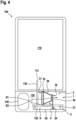
- Fig. 4 shows purely schematically a refrigeration device 100 in the form of a refrigerator with a cooling compartment 110 for storing refrigerated goods, such as food or beverages, a machine room 120 and a heat exchanger arrangement 1 according to claim 1.
- the refrigeration device 100 has a refrigerant circuit (not fully shown) to extract heat from the refrigeration compartment 110 by circulating a refrigerant. and thereby cool the cooling compartment 110.
- the heat exchanger arrangement 1 is part of the refrigerant circuit and serves to condense the gaseous refrigerant compressed by a compressor 140, which can also be arranged in the machine room 120.
- a condensate line 130 may be provided, which fluidically connects the interior of the cooling compartment 110 to the machine room and opens into the evaporation tray 2 of the heat exchanger arrangement 1. Condensate that forms in the cooling compartment 110 can thus be drained through the condensate line 130 into the condensate or evaporation tray 2.
- the condensate tray 2 has a bottom 20 and a peripheral wall 21.
- the base 20 may be a flat, for example, flat plate.
- the peripheral wall 21 extends from the base 20 and protrudes in a vertical direction or vertical direction V from the base 20.
- the condensate tray 2 may, for example, have a rectangular periphery, optionally with rounded corners, as shown in Fig. 3 is shown by way of example.
- the peripheral wall 21 can be composed, for example, of a first side wall 21A, a second side wall 21B arranged opposite thereto, a third side wall 21C extending between the first and second side walls 21A, 21B, and a fourth side wall 21D arranged opposite the third side wall 21C and extending between the first and second side walls 21A, 21B, as shown in Fig. 3 is shown purely as an example. Of course, other peripheral shapes or designs of the peripheral wall 21 are also conceivable.
- the base 20 and the peripheral wall 21 define a receiving volume of the condensate tray 2.
- the condensate tray 2 can have an optional sealing rib 24.
- the sealing rib 24 protrudes from the bottom 20 of the condensate tray 2.
- the sealing rib 24 protrudes in the vertical direction V with a height h24 from a surface 20a of the bottom 20.
- the height h24 can, for example, be in a range between 2 mm and 15 mm.
- the sealing rib 24 can have a rectangular cross-section. However, other cross-sectional shapes are also conceivable. As in Fig.
- the optional sealing rib 24 extends between the first and second side walls 21A, 21B of the condensate tray 2.
- the sealing rib 24 can extend between opposite or circumferentially spaced sections 21A, 21B of the peripheral wall 21.
- the condensate or evaporation tray 2 can be made of a plastic material, e.g., a thermoplastic material.
- the optional sealing rib 24 can, for example, be formed integrally with the base 20 of the condensate tray 2.
- the heat exchanger 3 comprises a housing 30, a refrigerant line arrangement 33 and a fan 34.
- the housing 30 can be tubular or channel-shaped, for example, and has an inlet opening 31 and an outlet opening 32 located opposite thereto.
- the inlet opening 31 can, for example, have a rectangular circumference.
- the outlet opening 32 can, for example, have a circular circumference.
- the inlet opening 31 and the outlet opening 32 are connected by a housing wall 30A defining the cross-section of the housing 30.
- the housing 30 extends overall along a housing longitudinal direction L3.
- the housing 30 can be composed of several housing parts or implemented as a single piece as a continuous housing 30.
- the housing 30 can, for example, be formed from a plastic material.
- the refrigerant line arrangement 33 can be realized, for example, as an MCHE unit, as shown in Fig. 1 is shown purely by way of example.
- MCHE is an abbreviation for the term "Micro Channel Heat Exchanger.”
- the refrigerant line arrangement 33 can have a plurality of refrigerant channels 35 for conducting the refrigerant.
- a plurality of cooling plates or cooling fins 36 can also be provided, which are connected to the refrigerant channels 35 in order to increase the surface area of the refrigerant line arrangement 33. Between the refrigerant channels 35 and between the optional cooling fins 36, gaps are provided for the passage of cooling air. As shown in Fig.
- the refrigerant line arrangement 33 is in the inlet opening 31 of the housing 30. As shown in Fig. 1 As can be seen, the refrigerant line arrangement 33 can be arranged in the inlet opening 31 of the housing 30 in particular such that it fills the inlet opening 31.
- the cross-section or the circumference of the inlet opening 31 and the outer circumference of the refrigerant line arrangement 33 can be adapted to one another.
- the fan 34 is arranged in the outlet opening 32 of the housing 30.
- the fan 34 can be arranged in the outlet opening 32 such that the inlet opening 31 is located on a suction side of the fan 34.
- the fan 34 can thus suck in air through the inlet opening 31 and blow it out through the outlet opening 32 of the housing 30.
- air is sucked through the interstices of the refrigerant line arrangement 33 in order to cool the refrigerant line arrangement 33.
- a sealing plate 4 is provided, which protrudes from the housing 30 of the heat exchanger 3.
- the sealing plate 4 protrudes from the housing 30 transversely to the housing longitudinal direction L3.
- the sealing plate 4 can be designed in particular as a flat plate 4.
- the sealing plate 4 is realized as a flatly extending component which extends between a first end 41, which is located on the housing 30, in particular on the housing wall 30A, and a second end 42 located opposite the first end 41.
- the sealing plate 4 can be arranged, for example, in the region of the outlet opening 32 of the housing 30 of the heat exchanger 3.
- the sealing plate 4 can be formed integrally with the housing 30 of the heat exchanger 3.
- the heat exchanger 3 can be arranged opposite the condensate tray 2, in particular with respect to the vertical direction V, so that the sealing plate 4 is located facing the condensate tray 2.
- the sealing plate 4 protrudes into the condensate tray 2, whereby a bottom gap 5 is formed between the bottom 20 of the condensate tray 2 and the second end 42 of the sealing plate 4.
- the bottom gap 5 can, for example, have a clear width d5 between 1 mm and 10 mm, in particular between 2 mm and 3 mm.
- the peripheral wall 21 of the condensate tray 2 and the sealing plate 4 overlap with respect to the vertical direction V.
- the sealing plate 21 extends over an entire distance between opposing side walls 21A, 21B, in particular between the first and second side walls 21A, 21B.
- the sealing plate 4 Independently of the circumference of the evaporation or condensation tray 2 defined by the peripheral wall 21, the sealing plate 4 extends between opposing sections 21A, 21B of the peripheral wall 21.
- the sealing plate 4 and the optional sealing rib 24 can extend in particular along each other, optionally parallel to each other. As shown in Fig. 2 As shown, it can be provided in particular that the sealing plate 4 and the sealing rib 24 overlap with respect to the vertical direction V. An end 25 of the sealing rib 24 facing away from the surface 20a of the base 20 in this case protrudes further from the surface 20a of the base 20 than the second end 42 of the sealing plate 4 is spaced from the surface 20a of the base 20.
- the clear width d5 of the base gap 5 can be smaller than the height h24 of the sealing rib 24.
- the relative arrangement of the sealing plate 4 and the sealing rib 24 along one another forms an overlap gap 6 between the sealing plate 4 and the sealing rib 24.
- the overlap gap 6 can, for example, have a clear width d6 in a range between 0.2 mm and 10 mm, preferably between 0.3 mm and 5 mm.
- the heat exchanger arrangement 1 according to claim 1 can be arranged in the machine room 120 of the refrigeration appliance 100.
- the condensate line 130 has a first end 131, which is connected to the interior of the cooling compartment 110.
- a second end 132 of the condensate line 130 opens into the condensate tray 2.
- the condensate tray 2 has the optional sealing rib 24, the location at which the Condensate pipe 130 opens into the condensate tray 2 and the sealing plate 4 is located on the same side of the sealing rib 6, as shown in Fig. 4
- the sealing rib 24 divides the receiving volume into two different sized sub-volumes, as shown in the Fig. 1 , 3 and 4 is shown as an example.
- the sealing plate 24 can protrude into the larger or smaller partial volume. Figs. 1 to 4 For example, it is shown that the sealing plate 24 protrudes into the larger partial volume. Accordingly, Fig. 4 the condensate pipe 130 also into the larger partial volume.
- a cooling air flow S1 is sucked in by the fan 34 through the inlet opening 31 and guided via the refrigerant line arrangement 33 to cool the refrigerant. Since the sealing plate 4 protrudes into the condensate tray 2 filled with condensate K, a seal between the inlet opening 31 and the outlet opening 32 of the housing 30 is improved outside the housing 30. A leakage flow S2 is thus reduced or even completely blocked, as shown in Fig. 4 is represented symbolically.
Landscapes
- Engineering & Computer Science (AREA)
- Physics & Mathematics (AREA)
- Mechanical Engineering (AREA)
- Thermal Sciences (AREA)
- General Engineering & Computer Science (AREA)
- Chemical & Material Sciences (AREA)
- Combustion & Propulsion (AREA)
- Heat-Exchange Devices With Radiators And Conduit Assemblies (AREA)
- Removal Of Water From Condensation And Defrosting (AREA)
Applications Claiming Priority (2)
| Application Number | Priority Date | Filing Date | Title |
|---|---|---|---|
| DE102020205750.8A DE102020205750A1 (de) | 2020-05-07 | 2020-05-07 | Wärmetauscheranordnung für ein Kältegerät und Kältegerät |
| PCT/EP2021/060935 WO2021224060A1 (de) | 2020-05-07 | 2021-04-27 | Wärmetauscheranordnung für ein kältegerät und ein kältegerät damit |
Publications (2)
| Publication Number | Publication Date |
|---|---|
| EP4146995A1 EP4146995A1 (de) | 2023-03-15 |
| EP4146995B1 true EP4146995B1 (de) | 2025-06-25 |
Family
ID=75787041
Family Applications (1)
| Application Number | Title | Priority Date | Filing Date |
|---|---|---|---|
| EP21723146.3A Active EP4146995B1 (de) | 2020-05-07 | 2021-04-27 | Wärmetauscheranordnung für ein kältegerät und ein kältegerät damit |
Country Status (6)
| Country | Link |
|---|---|
| US (1) | US12215916B2 (pl) |
| EP (1) | EP4146995B1 (pl) |
| CN (1) | CN115769036A (pl) |
| DE (1) | DE102020205750A1 (pl) |
| PL (1) | PL4146995T3 (pl) |
| WO (1) | WO2021224060A1 (pl) |
Families Citing this family (2)
| Publication number | Priority date | Publication date | Assignee | Title |
|---|---|---|---|---|
| TR202012072A2 (tr) * | 2020-07-29 | 2022-02-21 | Arcelik As | Bi̇r soğutucu ci̇haz |
| CN116878200A (zh) * | 2023-06-09 | 2023-10-13 | 合肥美的电冰箱有限公司 | 多联机冰箱及厨房电器 |
Citations (2)
| Publication number | Priority date | Publication date | Assignee | Title |
|---|---|---|---|---|
| US3225563A (en) * | 1964-08-07 | 1965-12-28 | Gamma Refrigeration Company In | Air conditioning devices |
| DE102015221659A1 (de) * | 2015-11-04 | 2017-05-04 | BSH Hausgeräte GmbH | Kältegerät mit einem Verdunstungsbehälter |
Family Cites Families (7)
| Publication number | Priority date | Publication date | Assignee | Title |
|---|---|---|---|---|
| US1943759A (en) * | 1932-09-19 | 1934-01-16 | Fourness Dev Corp Ltd | Condenser system for mechanical refrigeration |
| GB805286A (en) * | 1956-08-01 | 1958-12-03 | Hussmann British Refrigeration | Improved means for automatically dissipating the water derived as a result of de-frosting the evaporator of refrigerating apparatus |
| DE102008041481A1 (de) * | 2008-08-22 | 2010-02-25 | BSH Bosch und Siemens Hausgeräte GmbH | Ausnutzung der Verdunstungskälte zur Reduzierung des Energieverbrauchs |
| DE102011007415A1 (de) * | 2011-04-14 | 2012-10-18 | BSH Bosch und Siemens Hausgeräte GmbH | Verdunstungsvorrichtung für ein Kältegerät |
| DE102011007412A1 (de) | 2011-04-14 | 2012-10-18 | BSH Bosch und Siemens Hausgeräte GmbH | Kältegerät mit Verdunstungsschale |
| US9103599B2 (en) * | 2012-08-30 | 2015-08-11 | Wei-Ching Lee | Flake and method for reducing temperature of waste heat discharged from air conditioner |
| KR102004047B1 (ko) * | 2017-10-23 | 2019-07-25 | 엘지전자 주식회사 | 컴팩트 기계실을 위한 제상수 받이 및 이를 적용한 냉장고 |
-
2020
- 2020-05-07 DE DE102020205750.8A patent/DE102020205750A1/de active Pending
-
2021
- 2021-04-27 EP EP21723146.3A patent/EP4146995B1/de active Active
- 2021-04-27 WO PCT/EP2021/060935 patent/WO2021224060A1/de not_active Ceased
- 2021-04-27 US US17/923,034 patent/US12215916B2/en active Active
- 2021-04-27 CN CN202180032812.2A patent/CN115769036A/zh active Pending
- 2021-04-27 PL PL21723146.3T patent/PL4146995T3/pl unknown
Patent Citations (2)
| Publication number | Priority date | Publication date | Assignee | Title |
|---|---|---|---|---|
| US3225563A (en) * | 1964-08-07 | 1965-12-28 | Gamma Refrigeration Company In | Air conditioning devices |
| DE102015221659A1 (de) * | 2015-11-04 | 2017-05-04 | BSH Hausgeräte GmbH | Kältegerät mit einem Verdunstungsbehälter |
Also Published As
| Publication number | Publication date |
|---|---|
| EP4146995A1 (de) | 2023-03-15 |
| DE102020205750A1 (de) | 2021-11-11 |
| CN115769036A (zh) | 2023-03-07 |
| PL4146995T3 (pl) | 2025-09-22 |
| US20230221056A1 (en) | 2023-07-13 |
| US12215916B2 (en) | 2025-02-04 |
| WO2021224060A1 (de) | 2021-11-11 |
Similar Documents
| Publication | Publication Date | Title |
|---|---|---|
| EP4146995B1 (de) | Wärmetauscheranordnung für ein kältegerät und ein kältegerät damit | |
| WO2014131756A1 (de) | Wärmeübertrager | |
| EP3209883B1 (de) | Saugschalldämpfer für einen hermetisch gekapselten kältemittelverdichter | |
| EP2165867A1 (de) | Verdampfer mit Kondenswasserüberlaufschutz | |
| WO2022096334A1 (de) | Kältegerät | |
| DE102011080673A1 (de) | Kältemittelkondensatorbaugruppe | |
| EP4332476B1 (de) | Kältegerät | |
| CH713485A2 (de) | Kühlgerät mit aktiv gekühltem Maschinenraum. | |
| DE102022212851A1 (de) | Kältegerät und Verfahren zum Montieren eines Kältegeräts in einer Einbaunische | |
| WO2022194552A1 (de) | Kältegerät und wärmetauscherbaugruppe für ein kältegerät | |
| DE102022213434B3 (de) | Kältegerät | |
| DE102022207353A1 (de) | Kältegerät | |
| EP1816426B1 (de) | Wärmeübertrageranordnung, insbesondere eines Heckverdampfers in einem Kraftfahrzeug | |
| DE102016122310A1 (de) | Kondensator für eine Klimaanlage, insbesondere für ein Kraftfahrzeug | |
| WO2023105047A1 (de) | Wärmetauscherbaugruppe für ein kältegerät und kältegerät damit | |
| DE102022212849B4 (de) | Kältegerät | |
| DE69718978T2 (de) | Behälter zum Sammeln von Kondensat und Kühlgerät mit solchem Behälter | |
| EP1512564B1 (de) | Klimaanlage, insbesondere für ein Kraftfahrzeug | |
| DE102022213433A1 (de) | Kältegerät | |
| EP1669224B1 (de) | Klimaanlage mit einem Verdampfer mit Kondenswasserablauf | |
| WO2018137956A1 (de) | Dunstabzugshaube | |
| EP4155634A1 (de) | Kältegerät, verdichterbaugruppe für ein kältegerät und verfahren zum montieren der verdichterbaugruppe | |
| DE102011007216A1 (de) | Kältemittelkondensatorbaugruppe | |
| EP4576967A1 (de) | Anordnung zur kühlung eines wärmepumpenumrichters | |
| DE102022209900A1 (de) | Kältegerät |
Legal Events
| Date | Code | Title | Description |
|---|---|---|---|
| STAA | Information on the status of an ep patent application or granted ep patent |
Free format text: STATUS: UNKNOWN |
|
| STAA | Information on the status of an ep patent application or granted ep patent |
Free format text: STATUS: THE INTERNATIONAL PUBLICATION HAS BEEN MADE |
|
| PUAI | Public reference made under article 153(3) epc to a published international application that has entered the european phase |
Free format text: ORIGINAL CODE: 0009012 |
|
| STAA | Information on the status of an ep patent application or granted ep patent |
Free format text: STATUS: REQUEST FOR EXAMINATION WAS MADE |
|
| 17P | Request for examination filed |
Effective date: 20221207 |
|
| AK | Designated contracting states |
Kind code of ref document: A1 Designated state(s): AL AT BE BG CH CY CZ DE DK EE ES FI FR GB GR HR HU IE IS IT LI LT LU LV MC MK MT NL NO PL PT RO RS SE SI SK SM TR |
|
| DAV | Request for validation of the european patent (deleted) | ||
| DAX | Request for extension of the european patent (deleted) | ||
| GRAP | Despatch of communication of intention to grant a patent |
Free format text: ORIGINAL CODE: EPIDOSNIGR1 |
|
| STAA | Information on the status of an ep patent application or granted ep patent |
Free format text: STATUS: GRANT OF PATENT IS INTENDED |
|
| RIC1 | Information provided on ipc code assigned before grant |
Ipc: F28F 17/00 20060101ALI20250128BHEP Ipc: F25D 21/14 20060101AFI20250128BHEP |
|
| INTG | Intention to grant announced |
Effective date: 20250211 |
|
| GRAS | Grant fee paid |
Free format text: ORIGINAL CODE: EPIDOSNIGR3 |
|
| GRAA | (expected) grant |
Free format text: ORIGINAL CODE: 0009210 |
|
| STAA | Information on the status of an ep patent application or granted ep patent |
Free format text: STATUS: THE PATENT HAS BEEN GRANTED |
|
| AK | Designated contracting states |
Kind code of ref document: B1 Designated state(s): AL AT BE BG CH CY CZ DE DK EE ES FI FR GB GR HR HU IE IS IT LI LT LU LV MC MK MT NL NO PL PT RO RS SE SI SK SM TR |
|
| REG | Reference to a national code |
Ref country code: GB Ref legal event code: FG4D Free format text: NOT ENGLISH |
|
| REG | Reference to a national code |
Ref country code: CH Ref legal event code: EP |
|
| REG | Reference to a national code |
Ref country code: DE Ref legal event code: R096 Ref document number: 502021007853 Country of ref document: DE |
|
| REG | Reference to a national code |
Ref country code: CH Ref legal event code: EP |
|
| REG | Reference to a national code |
Ref country code: IE Ref legal event code: FG4D Free format text: LANGUAGE OF EP DOCUMENT: GERMAN |
|
| PG25 | Lapsed in a contracting state [announced via postgrant information from national office to epo] |
Ref country code: FI Free format text: LAPSE BECAUSE OF FAILURE TO SUBMIT A TRANSLATION OF THE DESCRIPTION OR TO PAY THE FEE WITHIN THE PRESCRIBED TIME-LIMIT Effective date: 20250625 |
|
| REG | Reference to a national code |
Ref country code: LT Ref legal event code: MG9D |
|
| PG25 | Lapsed in a contracting state [announced via postgrant information from national office to epo] |
Ref country code: NO Free format text: LAPSE BECAUSE OF FAILURE TO SUBMIT A TRANSLATION OF THE DESCRIPTION OR TO PAY THE FEE WITHIN THE PRESCRIBED TIME-LIMIT Effective date: 20250925 Ref country code: GR Free format text: LAPSE BECAUSE OF FAILURE TO SUBMIT A TRANSLATION OF THE DESCRIPTION OR TO PAY THE FEE WITHIN THE PRESCRIBED TIME-LIMIT Effective date: 20250926 |
|
| PG25 | Lapsed in a contracting state [announced via postgrant information from national office to epo] |
Ref country code: BG Free format text: LAPSE BECAUSE OF FAILURE TO SUBMIT A TRANSLATION OF THE DESCRIPTION OR TO PAY THE FEE WITHIN THE PRESCRIBED TIME-LIMIT Effective date: 20250625 |
|
| PG25 | Lapsed in a contracting state [announced via postgrant information from national office to epo] |
Ref country code: HR Free format text: LAPSE BECAUSE OF FAILURE TO SUBMIT A TRANSLATION OF THE DESCRIPTION OR TO PAY THE FEE WITHIN THE PRESCRIBED TIME-LIMIT Effective date: 20250625 |
|
| PG25 | Lapsed in a contracting state [announced via postgrant information from national office to epo] |
Ref country code: RS Free format text: LAPSE BECAUSE OF FAILURE TO SUBMIT A TRANSLATION OF THE DESCRIPTION OR TO PAY THE FEE WITHIN THE PRESCRIBED TIME-LIMIT Effective date: 20250925 |
|
| PG25 | Lapsed in a contracting state [announced via postgrant information from national office to epo] |
Ref country code: LV Free format text: LAPSE BECAUSE OF FAILURE TO SUBMIT A TRANSLATION OF THE DESCRIPTION OR TO PAY THE FEE WITHIN THE PRESCRIBED TIME-LIMIT Effective date: 20250625 |
|
| REG | Reference to a national code |
Ref country code: NL Ref legal event code: MP Effective date: 20250625 |
|
| PG25 | Lapsed in a contracting state [announced via postgrant information from national office to epo] |
Ref country code: NL Free format text: LAPSE BECAUSE OF FAILURE TO SUBMIT A TRANSLATION OF THE DESCRIPTION OR TO PAY THE FEE WITHIN THE PRESCRIBED TIME-LIMIT Effective date: 20250625 |
|
| PG25 | Lapsed in a contracting state [announced via postgrant information from national office to epo] |
Ref country code: PT Free format text: LAPSE BECAUSE OF FAILURE TO SUBMIT A TRANSLATION OF THE DESCRIPTION OR TO PAY THE FEE WITHIN THE PRESCRIBED TIME-LIMIT Effective date: 20251027 |
|
| PG25 | Lapsed in a contracting state [announced via postgrant information from national office to epo] |
Ref country code: IS Free format text: LAPSE BECAUSE OF FAILURE TO SUBMIT A TRANSLATION OF THE DESCRIPTION OR TO PAY THE FEE WITHIN THE PRESCRIBED TIME-LIMIT Effective date: 20251025 |
|
| PG25 | Lapsed in a contracting state [announced via postgrant information from national office to epo] |
Ref country code: SM Free format text: LAPSE BECAUSE OF FAILURE TO SUBMIT A TRANSLATION OF THE DESCRIPTION OR TO PAY THE FEE WITHIN THE PRESCRIBED TIME-LIMIT Effective date: 20250625 |
|
| PG25 | Lapsed in a contracting state [announced via postgrant information from national office to epo] |
Ref country code: CZ Free format text: LAPSE BECAUSE OF FAILURE TO SUBMIT A TRANSLATION OF THE DESCRIPTION OR TO PAY THE FEE WITHIN THE PRESCRIBED TIME-LIMIT Effective date: 20250625 |
|
| PG25 | Lapsed in a contracting state [announced via postgrant information from national office to epo] |
Ref country code: EE Free format text: LAPSE BECAUSE OF FAILURE TO SUBMIT A TRANSLATION OF THE DESCRIPTION OR TO PAY THE FEE WITHIN THE PRESCRIBED TIME-LIMIT Effective date: 20250625 |
|
| PG25 | Lapsed in a contracting state [announced via postgrant information from national office to epo] |
Ref country code: SK Free format text: LAPSE BECAUSE OF FAILURE TO SUBMIT A TRANSLATION OF THE DESCRIPTION OR TO PAY THE FEE WITHIN THE PRESCRIBED TIME-LIMIT Effective date: 20250625 |
|
| PG25 | Lapsed in a contracting state [announced via postgrant information from national office to epo] |
Ref country code: ES Free format text: LAPSE BECAUSE OF FAILURE TO SUBMIT A TRANSLATION OF THE DESCRIPTION OR TO PAY THE FEE WITHIN THE PRESCRIBED TIME-LIMIT Effective date: 20250625 |
|
| PG25 | Lapsed in a contracting state [announced via postgrant information from national office to epo] |
Ref country code: DK Free format text: LAPSE BECAUSE OF FAILURE TO SUBMIT A TRANSLATION OF THE DESCRIPTION OR TO PAY THE FEE WITHIN THE PRESCRIBED TIME-LIMIT Effective date: 20250625 |
|
| PG25 | Lapsed in a contracting state [announced via postgrant information from national office to epo] |
Ref country code: IT Free format text: LAPSE BECAUSE OF FAILURE TO SUBMIT A TRANSLATION OF THE DESCRIPTION OR TO PAY THE FEE WITHIN THE PRESCRIBED TIME-LIMIT Effective date: 20250625 |