EP4146571B1 - Transporter und verfahren zum transportieren von gegenständen - Google Patents
Transporter und verfahren zum transportieren von gegenständen Download PDFInfo
- Publication number
- EP4146571B1 EP4146571B1 EP20934660.0A EP20934660A EP4146571B1 EP 4146571 B1 EP4146571 B1 EP 4146571B1 EP 20934660 A EP20934660 A EP 20934660A EP 4146571 B1 EP4146571 B1 EP 4146571B1
- Authority
- EP
- European Patent Office
- Prior art keywords
- automatic guided
- transporter
- guided vehicles
- carrier
- predetermined path
- Prior art date
- Legal status (The legal status is an assumption and is not a legal conclusion. Google has not performed a legal analysis and makes no representation as to the accuracy of the status listed.)
- Active
Links
Images


Classifications
-
- G—PHYSICS
- G05—CONTROLLING; REGULATING
- G05D—SYSTEMS FOR CONTROLLING OR REGULATING NON-ELECTRIC VARIABLES
- G05D1/00—Control of position, course, altitude or attitude of land, water, air or space vehicles, e.g. using automatic pilots
- G05D1/02—Control of position or course in two dimensions
- G05D1/021—Control of position or course in two dimensions specially adapted to land vehicles
- G05D1/0287—Control of position or course in two dimensions specially adapted to land vehicles involving a plurality of land vehicles, e.g. fleet or convoy travelling
- G05D1/0291—Fleet control
- G05D1/0293—Convoy travelling
-
- G—PHYSICS
- G05—CONTROLLING; REGULATING
- G05D—SYSTEMS FOR CONTROLLING OR REGULATING NON-ELECTRIC VARIABLES
- G05D1/00—Control of position, course, altitude or attitude of land, water, air or space vehicles, e.g. using automatic pilots
- G05D1/02—Control of position or course in two dimensions
- G05D1/021—Control of position or course in two dimensions specially adapted to land vehicles
- G05D1/0212—Control of position or course in two dimensions specially adapted to land vehicles with means for defining a desired trajectory
- G05D1/0214—Control of position or course in two dimensions specially adapted to land vehicles with means for defining a desired trajectory in accordance with safety or protection criteria, e.g. avoiding hazardous areas
-
- G—PHYSICS
- G05—CONTROLLING; REGULATING
- G05D—SYSTEMS FOR CONTROLLING OR REGULATING NON-ELECTRIC VARIABLES
- G05D1/00—Control of position, course, altitude or attitude of land, water, air or space vehicles, e.g. using automatic pilots
- G05D1/02—Control of position or course in two dimensions
- G05D1/021—Control of position or course in two dimensions specially adapted to land vehicles
- G05D1/0231—Control of position or course in two dimensions specially adapted to land vehicles using optical position detecting means
- G05D1/0234—Control of position or course in two dimensions specially adapted to land vehicles using optical position detecting means using optical markers or beacons
-
- G—PHYSICS
- G05—CONTROLLING; REGULATING
- G05D—SYSTEMS FOR CONTROLLING OR REGULATING NON-ELECTRIC VARIABLES
- G05D1/00—Control of position, course, altitude or attitude of land, water, air or space vehicles, e.g. using automatic pilots
- G05D1/02—Control of position or course in two dimensions
- G05D1/021—Control of position or course in two dimensions specially adapted to land vehicles
- G05D1/0287—Control of position or course in two dimensions specially adapted to land vehicles involving a plurality of land vehicles, e.g. fleet or convoy travelling
- G05D1/0291—Fleet control
- G05D1/0295—Fleet control by at least one leading vehicle of the fleet
-
- G—PHYSICS
- G05—CONTROLLING; REGULATING
- G05D—SYSTEMS FOR CONTROLLING OR REGULATING NON-ELECTRIC VARIABLES
- G05D1/00—Control of position, course, altitude or attitude of land, water, air or space vehicles, e.g. using automatic pilots
- G05D1/60—Intended control result
- G05D1/617—Safety or protection, e.g. defining protection zones around obstacles or avoiding hazards
-
- G—PHYSICS
- G05—CONTROLLING; REGULATING
- G05D—SYSTEMS FOR CONTROLLING OR REGULATING NON-ELECTRIC VARIABLES
- G05D1/00—Control of position, course, altitude or attitude of land, water, air or space vehicles, e.g. using automatic pilots
- G05D1/60—Intended control result
- G05D1/69—Coordinated control of the position or course of two or more vehicles
- G05D1/695—Coordinated control of the position or course of two or more vehicles for maintaining a fixed relative position of the vehicles, e.g. for convoy travelling or formation flight
-
- G—PHYSICS
- G05—CONTROLLING; REGULATING
- G05D—SYSTEMS FOR CONTROLLING OR REGULATING NON-ELECTRIC VARIABLES
- G05D1/00—Control of position, course, altitude or attitude of land, water, air or space vehicles, e.g. using automatic pilots
- G05D1/60—Intended control result
- G05D1/69—Coordinated control of the position or course of two or more vehicles
- G05D1/698—Control allocation
- G05D1/6985—Control allocation using a lead vehicle, e.g. primary-secondary arrangements
Definitions
- Embodiments of the present disclosure generally relate to a transporter and a method for transporting an object.
- An automated guided vehicle or automatic guided vehicle is a mobile robot that follows along markers or paths on the floor, or uses radio waves, vision cameras, magnets, or lasers for navigation or any other navigation system. They are most often used in industrial applications to transport heavy materials around a large industrial building, such as a factory or warehouse.
- AGVs can tow objects behind or on top of them in trailers to which they can autonomously attach.
- the trailers can be used to move raw materials or finished products.
- AGVs can also store objects on a bed.
- the objects can be placed on a set of motorized rollers (conveyor) and then be pushed off by reversing the rollers.
- AGVs are employed in a variety of industries including automotive, aerospace, pulp, paper, metals, newspaper, and general manufacturing. Transporting materials such as food, linen or medicine in hospitals is also performed by AGVs.
- the US 2019/0001857 discloses a transport system and method for operating a transport system.
- the transport system includes a first mobile component and a second mobile component as well as a transport rack.
- Bearing rollers for moving the transport rack on a driving surface are disposed on the transport rack, in particular, the mobile component is drivable on the driving surface.
- Each mobile component has a linear axle and a control as well as wheels driven by an electric motor.
- the first mobile component is able to drive underneath the transport rack in a first region of the transport rack, and the second mobile component is able to drive underneath the transport rack in another, i.e. second, region of the transport rack.
- the transport rack is able to be raised by extending the linear axles of the mobile components, in particular is able to be raised in such a way that the bearing rollers of the transport rack lose physical contact with the driving surface
- towing-type transporter To transport large-sized objects such as car frames, conventional solutions typically employ a towing-type transporter or a large-sized transporter.
- the towing-type transporter comprises an AGV and a long trailer towed by the AGV.
- the large-sized transporter uses a large-sized AGV.
- this large-sized transporter can only be used for a limited number of objects.
- the transporter For objects that are not applicable, the transporter must to be replaced with one of another size.
- the towing-type transporter or the large-sized transporter often encounters problems such as large vibrations, instability, low safety, and poor adaptability.
- Embodiments of the present disclosure provide a transporter and a method of transporting an object.
- a transporter comprising at least one carrier comprising a plurality of coupling members; a support assembly adapted to support the carrier and enable the carrier to transport an object along a predetermined path; and a plurality of automatic guided vehicles connected to each other in a wired or wireless manner and configured to obtain kinematic information from one of the plurality of automatic guided vehicles designated as a leading automatic guided vehicle, and the plurality of automatic guided vehicles each comprising: a carrier connecting member coupled to the respective coupling member to enable the carrier to move with the plurality of automatic guided vehicles; and a patrol assembly adapted to enable the respective automatic guided vehicle to move along the predetermined path.
- the size and shape of the carrier can be arbitrarily adjusted to accommodate a variety of different sized objects or workpieces. In this way, costs for transporting the objects with large size can be significantly reduced while improving the adaptability of the transporter.
- the leading automatic guided vehicle configured to provide the kinematic information based at least on a radian of the predetermined path and a positional relationship between the plurality of coupling members relative to the predetermined path. In this way, the coordination between a plurality of automatic guided vehicles is improved while expanding the range of use.
- any other of the plurality of automatic guided vehicles can be re-designated as the leading automatic guided vehicle during a transportation of the object in case of a failure of the previously designated leading automatic guided vehicle. In this way, the control to the plurality of automatic guided vehicles can be more flexible with further improved reliability of transportation of the object.
- the at least one carrier comprises a plurality of carriers connected in series via connecting members arranged between the plurality of carriers.
- the transporter can transport longer objects or more objects at a time.
- the connecting members each comprise a coupling portion adapted to be coupled to the carrier connecting member of the respective automatic guided vehicle.
- the plurality of automatic guided vehicles are arranged in at least two columns along a direction parallel to the predetermined path. This arrangement enables transportation of objects with wide dimensions. That is, with the standard automatic guided vehicles, the shape and size of the carrier are flexible, thereby further improving the adaptability of the transporter.
- the plurality of automatic guided vehicles each comprise a monitoring member configured to provide safety information indicating whether an obstacle is within a predetermined range, and wherein the leading automatic guided vehicle is configured to provide the kinematic information to the plurality of automatic guided vehicles further based on the safety information from the plurality of automatic guided vehicles.
- the predetermined range is adjustable. In this way, this arrangement enables the monitoring member to adapt to a variety of different situations to further increase safety.
- the transporter further comprises a scheduling member configured to provide scheduling information on the predetermined path and a destination for the object to the leading automatic guided vehicle. In this way, the transporter is easier to manage.
- the plurality of automatic guided vehicles comprise at least two distance detection members each configured to provide distance information on a distance from the respective distance detection member to a reference marker, and wherein the leading automatic guided vehicle is configured to, in response to a request of lateral movement of the transporter, generate the kinematic information indicating the lateral movement based on the distance information.
- the movement mode of the transporter can be more flexible which further improves the adaptability.
- the kinematic information indicates speeds and/or moving directions of the plurality of automatic guided vehicles.
- a method of transporting an object comprises obtaining scheduling information indicating a predetermined path for at least one carrier carrying the object, the carrier comprising a plurality of coupling members coupled to respective carrier connecting members of a plurality of automatic guided vehicles, the plurality of automatic guided vehicles connected to each other in a wired or wireless manner; generating kinematic information for the plurality of automatic guided vehicles based on the obtained scheduling information; and providing the kinematic information to each of the plurality of automatic guided vehicles to cause each of the automatic guided vehicle to move along the predetermined path.
- generating the kinematic information comprises generating the kinematic information based at least on a radian of the predetermined path and a positional relationship between the plurality of coupling members relative to the predetermined path.
- generating the kinematic information comprises generating the kinematic information based on the safety information indicating whether an obstacle is within a predetermined range.
- obtaining the scheduling information comprises obtaining the scheduling information indicating the predetermined path and a destination for the object from a scheduling member.
- generating the kinematic information further comprises in response to a request of lateral movement of the transporter, generating the kinematic information indicating the lateral movement based on a distance information on a distance from a distance detection member to a reference marker.
- the term “comprises” and its variants are to be read as open terms that mean “comprises, but is not limited to.”
- the term “based on” is to be read as “based at least in part on.”
- the term “one embodiment” and “an embodiment” are to be read as “at least one embodiment”
- the term “another embodiment” is to be read as “at least one other embodiment.”
- the terms “first,” “second,” and the like may refer to different or same objects. Other definitions, explicit and implicit, may be comprised below. A definition of a term is consistent throughout the description unless the context clearly indicates otherwise.
- the towing-type transporter uses an automatic guided vehicle and a trailer towed by the automatic guided vehicle at one end of the trailer. That is, another end of the trailer lacks support by the automatic guided vehicle to form a "null rear end". Due to this towing structures of the transporter, the vibration on the automatic guided vehicle will be amplified and applied on the carrier, resulting in a large vibration of the trailer, which impairs the transportation and quality of the transported objects.
- the pivoting structure of the automatic guided vehicle at the front end of the carrier results in a larger rear area passed by the rear of the carrier than the front area passed by the front when turning.
- the front safety means aiming to monitor the front area cannot completely cover the rear area. Due to the lack of rear safety means for monitoring the rear area, there is a risk of harm to people or items within the rear area when the transporter turns.
- conventional solutions also include a type of transporter using a large automatic guided vehicle to transport objects of large sizes.
- a large automatic guided vehicle By using the large automatic guided vehicle with a size slightly larger than or similar to the size of a carrier supported by the automatic guided vehicle, the objects of large sizes can be transported.
- embodiments of the present disclosure provide a transporter and a method of transporting an object.
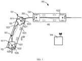
- FIG. 1 shows a schematic diagram of a transporter moving from a position to another position along a predetermined path
- FIG. 2 shows top and side views of an automatic guided vehicle
- FIG. 3 shows top and side views of a carrier.
- the transporter 100 comprise at least one carrier 101, a support assembly 103 for supporting the carrier 101 and a plurality of automatic guided vehicles 102.
- the support assembly 103 in some embodiments may comprise carter wheels 1031 or universal wheels which enable the carrier 101 to transport the object along a predetermined path 202.
- carter wheels 1031 or universal wheels improves steering freedom and flexibility of the carrier 101.
- the above embodiments where the support assembly 103 comprises carter wheels 1031 or universal wheels are merely for illustrative purposes, without suggesting any limitation as to the scope of the present disclosure. Any other suitable support assembly 103 is also possible.
- the support assembly 103 may also comprise track wheels or the like.
- the carrier 101 is driven to move by the plurality of automatic guided vehicles 102.
- Each of the plurality of automatic guided vehicles 102 may be a standard automatic guided vehicle 102 with the same specifications and configuration.
- the standard automatic guided vehicle 102 objects of various sizes can be transported by the transporter 100.
- the carrier 101 which is easily manufactured with relatively low costs. That is, the size and/or shape of the carrier 101 may be easily adjusted to meet the requirements of objects of different sizes and shapes, which will be discussed in detail below.
- the carrier 101 comprises a plurality of coupling members 1011 to drive the automatic guided vehicle 102 to the carrier 101.
- the automatic guided vehicles 102 each comprise a carrier connecting member 1021 coupled to the respective coupling member 1011, as shown in FIGs. 2 and 3 . By coupling the carrier connecting member 1021 to the respective coupling member 1011, the carrier 101 can be driven by the plurality of automatic guided vehicles 102.
- the carrier connecting member 1021 may comprise a pin that can be lifted or lowered manually or automatically.
- the coupling member 1011 may comprise an aperture for receiving the lifted pin.
- each automatic guided vehicle 102 may be moved manually or automatically to a position where the pin is vertically aligned with the aperture of the carrier 101. Then the pin is lifted to insert into the aperture to achieve the coupling.
- there is any suitable means such as an elastic member or the like arranged on the pin or in the aperture to reduce fit clearance there between.
- the coupling of the carrier 101 and the automatic guided vehicle 102 is easier to achieve or control, thereby reducing control difficulty.
- the coupling member 1011 may be arranged adjacent to ends of the carrier 101, as shown in FIGs. 1 and 3 .
- the automatic guided vehicles 102 are coupled to positions of the carrier 101 adjacent to the ends. That is, there is always one automatic guided vehicle 102 coupled to an rear end of the carrier 101, thereby to reduce the vibration due to the "null rear end" and thus improve the stability of the transporter 100.
- the carrier connecting member 1021 comprises the pin are discussed merely for illustrative purposes, without suggesting any limitation as to the scope of the present disclosure. Any other suitable arrangement or structure is also feasible.
- the carrier connecting member 1021 and the coupling member 1011 may also employ magnetic arrangements which can be coupled to each other by magnetic force.
- the size and/or shape of the carrier 101 may be adjusted to meet the requirements of objects of different sizes and shapes.
- FIG. 4 which shows a schematic diagram of a transporter 100 with a large width carrier 101
- the carrier 101 is driven by the plurality of automatic guided vehicles 102 arranged in two columns along a direction parallel to the determined path 202. With the arrangement, objects of large width can be well supported and transported by the transporter 100.
- the number of the automatic guided vehicles 102 arranged in one column may be different from or equal to that of the automatic guided vehicles 102 arranged in the other columns.
- the carrier 101 is of a triangular shape, there may be two automatic guided vehicles 102 arranged in one column and one automatic guided vehicles 102 arranged in another column.
- the distance between the automatic guided vehicles 102 arranged in each column may be different or the same.
- the distance of two automatic guided vehicles 102 arranged in the column adjacent to the long side of the trapezoidal shape may be larger than those arranged adjacent to the short side.
- the angle between adjacent two columns may also be zero or non-zero. That is, the columns may be parallel to each other or form a non-zero angle.
- two columns of the automatic guided vehicles 102 may be arranged along bevel sides of the trapezoidal shape.
- the plurality of automatic guided vehicles 102 there are two automatic guided vehicles 102 as a necessary unit.
- Other automatic guided vehicles 102 (if any) than the two automatic guided vehicles 102 may be arranged, as an option, at any suitable positions according to the size and/or shape of the carrier 101.
- the automatic guided vehicles 102 in more than two columns.
- three or four columns of the automatic guided vehicles 102 may also be employed.
- the number of the automatic guided vehicles in each column is not limited to 2 as shown in FIG. 4 , and more than 2 automatic guided vehicles in each column are also possible.
- the plurality of automatic guided vehicles 102 can move according to kinematic information provided by the leading one of the automatic guided vehicles 102, thereby driving the carrier 101 to move, which will be discussed in detail below.
- the shape of the carrier 101 is not limited to the rectangle as shown in FIGs. 3 and 4 .
- the carrier 101 may be of a triangular or trapezoidal shape or the like. In this event, the coupling positions of the automatic guided vehicles 102 may also be adjusted accordingly.
- the at least one carrier 101 may comprise a plurality of carriers 101.
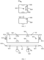
- FIG. 5 shows top and side views of a transporter with a plurality of carriers 101.
- the carriers 101 of different or same shapes and sizes can be connected or coupled to each other to transport objects of larger size or a more significant number. In this way, the transporter's capacity and applicability can be significantly improved without increasing costs.
- the plurality of carriers 101 may be connected in series via connecting members 1013 arranged between the plurality of carriers 101.
- the connecting members 1013 may be arranged on one or both ends of the carrying tray 1012.
- the connecting members 1013 arranged on adjacent carriers 101 can be coupled to each other by suitable coupling means such as magnetic connections, bolt connections or snap connections.
- each connecting member 1013 may comprise a coupling portion 1014, as shown in FIGs. 3 and 5 .
- the coupling portion 1014 may be coupled to the carrier connecting member 1021 of the respective automatic guided vehicle 102. In this way, the number of automatic guided vehicles 102 for driving the plurality of carriers 101 can be significantly reduced.
- the carrier connecting member 1021 is coupled to the coupling member 1011 of the carrier 101, six automatic guided vehicles are needed for the three carriers 101.
- some carrier connecting members 1021 are coupled to the coupling portions 1014 of the connecting members 1013 as shown in FIG. 5 , only N+1 automatic guided vehicles are needed for N carriers 101. As a result, the costs of the transporter 100 can be reduced.
- the automatic guided vehicles 102 each comprise patrol assemblies 1022 which enable the automatic guided vehicles 102 to separately travel along the predetermined path 202 according to the kinematic information, which will be discussed further below.
- Example implementations of the patrol assembly 1022 include, but are not limited to, a guide tape assembly, a laser target navigation assembly, or a wired or slotted assembly.
- the plurality of automatic guided vehicles 102 are communicatively connected to each other in a wired or wireless manner.
- the plurality of automatic guided vehicles 102 may be coupled to exchange data/information through Bluetooth, Wi-Fi, near field communication (NFC) and/or any suitable communication protocols. This arrangement can be conducive to the transmission of data between the plurality of automatic guided vehicles 102, thereby to facilitate the control to the plurality of automatic guided vehicles 102.
- one of the automatic guided vehicles 102 functions as a leading automatic guided vehicle 1023 to obtain scheduling information.
- the scheduling information at least indicates the predetermined path 202 along which the automatic guided vehicles 102 shall move.
- scheduling information can be provided by a scheduling member 104 of the transporter 100.
- the scheduling member 104 in some embodiments may be a control system such as a fleet management system used in a factory to manage or schedule production processes. In this way, only data communication between the scheduling member 104 and the leading automatic guided vehicle 1023 is required to obtain the scheduling information. As a result, the complexity of control of the transporter 100 can be significantly reduced.
- the scheduling member 104 may be coupled to the automatic guided vehicles 102 in a wired or wireless manner.
- any of the plurality of automatic guided vehicles 102 can be designated as a leading automatic guided vehicle to obtain the scheduling information.
- the automatic guided vehicle at a leading position in the moving direction may be designated as the leading automatic guided vehicle 1023 to facilitate task execution.
- the automatic guided vehicle on the predetermined path and at the leading position in the moving direction may be designated as the leading automatic guided vehicle 1023.
- the leading automatic guided vehicle in the moving direction may be designated as the leading automatic guided vehicle 1023.
- a designation principle for the leading automatic guided vehicle 1023 is conducive to the transportation of objects with high safety performance.
- any other of the plurality of automatic guided vehicles 102 can be re-designated as a new leading automatic guided vehicle 1023 to achieve the role of the leading automatic guided vehicle 1023.
- the failure of the designated leading automatic guided vehicle 1023 may comprise any error or defect that may affect the achievement of its role as a leading automatic guided vehicle. In this way, the flexibility of control and the reliability of transportation can be further improved.
- each automatic guided vehicle 102 can move according to respective kinematic information to transport objects.
- the kinematic information for each automatic guided vehicle 102 is provided by the leading automatic guided vehicle 1023.
- FIG. 6 shows a flowchart illustrating a method 400 of transporting an object with the transporter 100.
- the method can be implemented as program codes stored in a memory of each automatic guided vehicle 102, which can be performed by a processor of the automatic guided vehicle 102.
- the processer of the leading automatic guided vehicle 1023 will obtain scheduling information at least on a predetermined path 202.
- the leading automatic guided vehicle 1023 may also be designated.
- the scheduling information may also indicate other suitable information such as a destination of an object to be transported. Based on the scheduling information, at block 420, the leading automatic guided vehicle 1023 can generate kinematic information for the plurality of automatic guided vehicles 102.
- the generated kinematic information is then provided to the plurality of automatic guided vehicles 102.
- the kinematic information may at least indicate speeds and/or moving directions of the plurality of automatic guided vehicles 102. Then the plurality of automatic guided vehicles 102 can be moved based on the kinematic information.
- the leading automatic guided vehicle 1023 may also obtain the status information from the plurality of automatic guided vehicles 102 and provide the status information to the scheduling member 104, for example.
- the leading automatic guided vehicle 1023 will generate the kinematic information for each automatic guided vehicle 102.
- the kinematic information for the rear automatic guided vehicle can merely comprise a speed value at which it travels.
- the speed of the rear automatic guided vehicle is configured to be the same as that of the leading automatic guided vehicle 1023. In this way, the coordination of the movement between the leading and rear automatic guided vehicles is improved, thereby preventing the stress on the carrier 101 due to inconsistent speeds of the two automatic guided vehicles.
- the conditions described above for leading and rear automatic guided vehicles are also applicable to other cases of the automatic guided vehicles moving along the predetermined path, as shown in FIG. 5 , for example.
- the positional relationship between the plurality of coupling members 1011 may comprise a distance of the coupling members 1011 away from the predetermined path 202.
- the proportional relationship between speeds of the leading automatic vehicle 1023 and the automatic guided vehicles 102 (referred to as bias automatic guided vehicles for ease of discussion) which are not on the predetermined path 202 can be determined.
- the moving directions of the bias automatic guided vehicles 102 can also be determined.
- each automatic guided vehicle 102 may comprise a monitoring member 1024, as shown in FIGs. 2 and 7 .
- the monitoring member 1024 may be arranged at a suitable portion of the automatic guided vehicle 102 facilitating the detection of an obstacle within a predetermined range 203.
- the predetermined range may extend beyond the edges of the carrier 101 to further improve the safety.
- the monitoring member 1024 can provide safe information indicating whether an obstacle is within the predetermined range 203. Then the leading automatic guided vehicle 1023 can provide the kinematic information to the plurality of automatic guided vehicles 102 further based on the safety information from all of the plurality of automatic guided vehicles 102. To this end, in some embodiments, the leading automatic guided vehicle 1023 may generate the kinematic information further based on the safety information indicating whether an obstacle is within a predetermined range 203. For example, if there are obstacles within the predetermined range 203 during transportation, which can be detected by the monitoring member 1024, the monitoring member 1024 then provides the safety information on the obstacles in the predetermined range 203 to the leading automatic guided vehicle 1023. Then the leading automatic guided vehicle 1023 provides the kinematic information on reducing the speeds of the automatic guided vehicle 102 to zero to improve the safety.
- the predetermined range 203 may be adjustable.
- the adjusting of the predetermined range 203 can be achieved by adjusting an orientation of the respective automatic guided vehicle 102 according to the position of the automatic guided vehicle.
- the rear automatic guided vehicle 102 may be controlled to face forward in the moving direction when the transporter turns. In this way, the monitoring member 1024 of the rear automatic guided vehicle 102 can detect obstacles within the rear area of the transporter 100 thereby improving the safety of the transporter 100.
- the predetermined range 203 may also be adjusted by adjusting parameters of the monitoring member 1024 associated with a shape and size of a detection range of the monitoring member 1024. That is, the predetermined range 203 can be enlarged, reduced, shifted or adjusted to change a shape of the predetermined range 203 to cover the required detection range and thus to facilitate the detection. In some embodiments, the predetermined range 203 may also be adjusted to ignore a certain range to avoid false detection.
- the destination of transported objects may require lateral movement of the transporter 100 to facilitate the manufacture of the objects, for example.
- the transporter 100 needs to move to a position laterally aligned with the destination, a request of the lateral movement of the transporter 100 may be generated.
- a distance between the transporter 100 and the destination needs to be detected.
- the plurality of automatic guided vehicles 102 may comprise at least two distance detection members 1025.
- the at least two distance detection members 1025 may be respectively arranged on the at least two automatic guided vehicles 102 at a leading position in the lateral movement direction.
- all the automatic guided vehicles 102 may each comprise a distance detection member 1025, as shown in FIGs. 2 and 8 .
- the distance detection member 1025 may be located at a suitable portion of the automatic guided vehicle 102.
- the distance detection member 1025 may be arranged at the same side of the automatic guided vehicle 102 as the monitoring member 1024.
- the automatic guided vehicles 102 at the leading position in the lateral movement direction may be re-oriented to cause the distance detection member 1025 towards the destination, as shown in FIG. 8 .
- a reference marker 201 may be located adjacent to the destination as a reference for providing the distance information.
- the reference marker 201 may be any suitable structure.
- the reference marker 201 may be a wall or an edge adjacent to the destination.
- the reference marker 201 may also be a virtual wall or a magnetic tape.
- Each of the distance detection members 1025 of the automatic guided vehicles 102 at a leading position in the lateral movement direction can provide distance information on the obtained distance from the respective distance detection member 1025 to the reference marker 201. Then, in response to the request of lateral movements of the transporter 100, the leading automatic guided vehicle 1023 can generate and provide the kinematic information indicating the lateral movement based on the distance information. In this way, the transporter 100 can be moved to the destination accurately.
- the distance detection member 1025 of the leading automatic guided vehicle 1023 may provide distance information on the obtained distance D2.
- the distance detection member 1025 of the other automatic guided vehicle 102 than the leading automatic guided vehicle 102 as shown in FIG. 8 may provide distance information on the obtained distance D1.
- the transporter 100 can be placed at any appropriate angle or position relative to the reference marker 201.
- the adaptability of the transporter 100 can be significantly improved. Furthermore, the monitoring member 1024 of the automatic guided vehicle 102 can detect the rear area of the transporter 100, thereby improving the safety of the transporter 100.
Landscapes
- Engineering & Computer Science (AREA)
- Physics & Mathematics (AREA)
- Aviation & Aerospace Engineering (AREA)
- Radar, Positioning & Navigation (AREA)
- Remote Sensing (AREA)
- General Physics & Mathematics (AREA)
- Automation & Control Theory (AREA)
- Electromagnetism (AREA)
- Control Of Position, Course, Altitude, Or Attitude Of Moving Bodies (AREA)
Claims (13)
- Transporter, umfassend:mindestens einen Träger (101), der eine Vielzahl von Kupplungselementen (1011 oder 1014) umfasst;eine Stützanordnung (103), die so angepasst ist, dass sie den Träger (101) stützt und es dem Träger (101) ermöglicht, ein Objekt entlang eines vorbestimmten Weges (202) zu transportieren; undeine Vielzahl von automatisch geführten Fahrzeugen (102), die miteinander auf drahtgebundene oder drahtlose Weise verbunden sind und so konfiguriert sind, dass sie kinematische Informationen von einem der Vielzahl von automatisch geführten Fahrzeugen (102) erhalten, das als führendes automatisch geführtes Fahrzeug (1023) bezeichnet wird, und wobei die Vielzahl von automatisch geführten Fahrzeugen (102) jeweils umfasst:ein Trägerverbindungselement (1021), das mit einem entsprechenden Kupplungselement (1011) der Vielzahl von Kupplungselemente gekoppelt ist, um dem Träger (101) zu ermöglichen, sich mit der Vielzahl von automatisch geführten Fahrzeugen (102) zu bewegen; undeine Patrouillenbaugruppe (1022), die so ausgelegt ist, dass sie einem entsprechenden automatisch geführten Fahrzeug (102) der Vielzahl von automatisch geführten Fahrzeugen ermöglicht, sich entlang des vorbestimmten Weges zu bewegen; wobei fernerdas führende automatisch geführte Fahrzeug (1023) so konfiguriert ist, dass es die kinematischen Informationen auf der Grundlage mindestens eines Radianten des vorbestimmten Pfads (202) und einer Positionsbeziehung zwischen der Vielzahl von Kupplungselementen (1011) relativ zu dem vorbestimmten Pfad (202) bereitstellt; wobeidie Positionsbeziehung zwischen der Vielzahl von Kupplungselementen (1011) einen Abstand der Kupplungselemente (1011) von dem vorbestimmten Pfad umfasst.
- Transporter nach Anspruch 1, wobei jedes andere der Vielzahl von automatisch geführten Fahrzeugen (102) während eines Transports des Objekts im Falle eines Ausfalls des zuvor bestimmten führenden automatisch geführten Fahrzeugs (1023) als führendes automatisch geführtes Fahrzeug (1023) neu bestimmt werden kann.
- Transporter nach Anspruch 1, wobei der mindestens eine Träger (101) umfasst:
eine Vielzahl von Trägern (101), die in Reihe über Verbindungselemente (1013) verbunden sind, die zwischen der Vielzahl von Trägern (101) angeordnet sind. - Transporter nach Anspruch 2, wobei die Verbindungselemente (1013) jeweils einen Kupplungsabschnitt (1014) umfassen, der so ausgelegt ist, dass er mit dem Trägerverbindungselement (1021) des jeweiligen automatisch geführten Fahrzeugs (102) gekoppelt werden kann.
- Transporter nach Anspruch 1, wobei die Vielzahl von automatisch geführten Fahrzeugen (102) in mindestens zwei Reihen entlang einer Richtung parallel zu dem vorbestimmten Weg (202) angeordnet sind.
- Transporter nach Anspruch 1, wobei die Vielzahl von automatisch geführten Fahrzeugen (102) jeweils ein Überwachungselement (1024) umfasst, das so konfiguriert ist, dass es Sicherheitsinformationen bereitstellt, die anzeigen, ob sich ein Hindernis innerhalb eines vorgegebenen Bereichs (203) befindet, und wobei das führende automatisch geführte Fahrzeug (1023) so konfiguriert ist, dass es die kinematischen Informationen für die Vielzahl von automatisch geführten Fahrzeugen (102) bereitstellt, ferner basierend auf den Sicherheitsinformationen von der Vielzahl von automatisch geführten Fahrzeugen (102),
wobei der vorbestimmte Bereich vorzugsweise einstellbar ist. - Transporter nach Anspruch 1, ferner umfassend:
ein Planungselement (104), das so konfiguriert ist, dass es dem führenden automatisch geführten Fahrzeug (102) Planungsinformationen über den vorbestimmten Weg (202) und ein Ziel für das Objekt bereitstellt. - Transporter nach Anspruch 7, wobei die Vielzahl von automatisch geführten Fahrzeugen (102) mindestens zwei Abstandserfassungselemente (1025) umfasst, die jeweils so konfiguriert sind, dass sie Abstandsinformationen über einen Abstand von dem jeweiligen Abstandserfassungselement (1025) zu einer Referenzmarkierung (201) bereitstellen, und
wobei das führende automatisch geführte Fahrzeug (1023) so konfiguriert ist, dass es als Reaktion auf eine Anforderung einer seitlichen Bewegung des Transporters (100) die kinematischen Informationen erzeugt, die die seitlichen Bewegungen auf der Grundlage der Abstandsinformationen anzeigen. - Transporter nach Anspruch 1, wobei die kinematischen Informationen Geschwindigkeiten und/oder Bewegungsrichtungen der Vielzahl von automatisch geführten Fahrzeugen (102) anzeigen.
- Verfahren zum Transportieren eines Objekts, umfassend:Erhalten von Planungsinformationen, die einen vorbestimmten Weg (202) für mindestens einen Träger (101) anzeigen, der das Objekt trägt, wobei der Träger (101) eine Vielzahl von Kupplungselementen (1011 oder 1014) umfasst, die mit jeweiligen Trägerverbindungselementen (1021) einer Vielzahl von automatisch geführten Fahrzeugen (102) verbunden sind, wobei die Vielzahl von automatisch geführten Fahrzeugen (102) auf verdrahtete oder drahtlose Weise miteinander verbunden sind;Erzeugen von kinematischen Informationen für die Vielzahl von automatisch geführten Fahrzeugen (102) auf der Grundlage der erhaltenen Planungsinformationen, undBereitstellen der kinematischen Informationen für jedes der Vielzahl von automatisch geführten Fahrzeugen (102), um zu bewirken, dass sich jedes der Vielzahl von automatisch geführten Fahrzeugen (102) entlang des vorbestimmten Weges (202) bewegt; wobei das Erzeugen der kinematischen Informationen umfasst:Erzeugen der kinematischen Information auf der Grundlage mindestens eines Radianten des vorbestimmten Weges (202) und einer Positionsbeziehung zwischen der Vielzahl von Kupplungselementen (1011) relativ zu dem vorbestimmten Weg (202); wobeidie Positionsbeziehung zwischen der Vielzahl von Kupplungselementen (1011) einen Abstand der Kupplungselemente (1011) von dem vorbestimmten Weg umfasst.
- Verfahren nach Anspruch 10, wobei das Erzeugen der kinematischen Information umfasst:
Erzeugen der kinematischen Information auf der Grundlage der Sicherheitsinformation, die angibt, ob sich ein Hindernis innerhalb eines vorbestimmten Bereichs (203) befindet. - Verfahren nach Anspruch 10, wobei das Erhalten der Planungsinformation umfasst:
Erhalten der Planungsinformation, die den vorbestimmten Weg (202) und ein Ziel für das Objekt angibt, von einem Planungselement (104). - Verfahren nach Anspruch 10, wobei das Erzeugen der kinematischen Information umfasst:
Erzeugen der kinematischen Information, die die seitlichen Bewegungen anzeigt, als Reaktion auf eine Anforderung einer seitlichen Bewegung des Transporters (100) auf der Grundlage einer Abstandsinformation über einn Abstand von einem Abstandserfassungselement (1025) zu einer Referenzmarkierung (201).
Applications Claiming Priority (1)
| Application Number | Priority Date | Filing Date | Title |
|---|---|---|---|
| PCT/CN2020/088691 WO2021223085A1 (en) | 2020-05-06 | 2020-05-06 | Transporter and method for transporting object |
Publications (3)
| Publication Number | Publication Date |
|---|---|
| EP4146571A1 EP4146571A1 (de) | 2023-03-15 |
| EP4146571A4 EP4146571A4 (de) | 2024-01-24 |
| EP4146571B1 true EP4146571B1 (de) | 2024-12-04 |
Family
ID=78467735
Family Applications (1)
| Application Number | Title | Priority Date | Filing Date |
|---|---|---|---|
| EP20934660.0A Active EP4146571B1 (de) | 2020-05-06 | 2020-05-06 | Transporter und verfahren zum transportieren von gegenständen |
Country Status (4)
| Country | Link |
|---|---|
| US (1) | US12111667B2 (de) |
| EP (1) | EP4146571B1 (de) |
| CN (1) | CN115003612B (de) |
| WO (1) | WO2021223085A1 (de) |
Family Cites Families (39)
| Publication number | Priority date | Publication date | Assignee | Title |
|---|---|---|---|---|
| SE503925C2 (sv) * | 1995-05-26 | 1996-09-30 | Jan Eriksson | Järnvägsvagn |
| US7185591B2 (en) | 2001-03-27 | 2007-03-06 | General Electric Company | Hybrid energy off highway vehicle propulsion circuit |
| CA2692306C (en) * | 2003-05-01 | 2013-10-15 | Daifuku Co., Ltd. | Conveyance apparatus using movable bodies |
| US8192137B2 (en) * | 2004-05-03 | 2012-06-05 | Jervis B. Webb Company | Automatic transport loading system and method |
| JP2005350147A (ja) * | 2004-06-08 | 2005-12-22 | Star Techno Kk | フリーフロー搬送システム |
| JP4462156B2 (ja) * | 2005-03-15 | 2010-05-12 | パナソニック電工株式会社 | 自律移動装置 |
| CN101379368A (zh) | 2006-02-01 | 2009-03-04 | 杰维斯·B·韦布国际公司 | 可变路径自动导引车辆 |
| JP4650306B2 (ja) * | 2006-03-15 | 2011-03-16 | 株式会社ダイフク | 転換設備 |
| AU2009305103B2 (en) * | 2008-10-17 | 2014-08-07 | Frank Wegner Donnelly | Rail conveyance system for mining |
| US8240748B2 (en) * | 2008-10-28 | 2012-08-14 | Draco Trust | Modular vehicle and triangular truss support system therefor |
| BRPI1006814A2 (pt) | 2009-01-17 | 2016-04-12 | Boomerang Systems Inc | conjunto de antenas de posicionamento de deslocamento variável para a orientação potenciada de veículos guiados automaticamente (agvs) |
| CN101792064B (zh) * | 2010-01-26 | 2013-06-05 | 北京京鹏环球科技股份有限公司 | 一种穴盘移栽输送装置 |
| JP5503419B2 (ja) * | 2010-06-03 | 2014-05-28 | 株式会社日立製作所 | 無人搬送車および走行制御方法 |
| DE102010023318A1 (de) * | 2010-06-10 | 2011-12-15 | Voith Patent Gmbh | Vorrichtung zum Verschwenken einer oder mehrerer Bugklappen eines spurgeführten Fahrzeuges sowie Bugklappenmodul |
| IL222208A (en) * | 2012-09-27 | 2017-02-28 | Israel Aerospace Ind Ltd | Loading system, method and facility |
| US8761989B1 (en) * | 2012-12-18 | 2014-06-24 | Jervis B. Webb Company | Method of material handling with automatic guided vehicles |
| US8798841B1 (en) * | 2013-03-14 | 2014-08-05 | GM Global Technology Operations LLC | System and method for improving sensor visibility of vehicle in autonomous driving mode |
| CN103223960B (zh) * | 2013-03-28 | 2015-04-29 | 燕山大学 | 一种巷道无轨式液压载重车的协调直行、转向控制方法 |
| EP2832622B1 (de) * | 2013-07-29 | 2016-05-25 | Siemens S.A.S. | Methode und Vorrichtungen zur Kontrolle der korrekten Aufgleisung eines spurgeführten Fahrzeugs |
| DE102013218391A1 (de) | 2013-09-13 | 2015-03-19 | Krones Ag | Vorrichtung und Verfahren zum Bewegen von Transportelementen in einer Behälterbehandlungsanlage |
| CN103587869B (zh) * | 2013-11-05 | 2015-07-08 | 无锡普智联科高新技术有限公司 | 基于总线方式的多机器人物流仓储系统及其控制方法 |
| AU2014388617B2 (en) * | 2014-03-28 | 2018-02-15 | Daifuku Co., Ltd. | Transport conveyor and transport unit |
| US9389614B2 (en) | 2014-04-08 | 2016-07-12 | Unitronics Automated Solutions Ltd | System and method for tracking guiding lines by an autonomous vehicle |
| DK178276B1 (en) * | 2014-12-19 | 2015-10-26 | Conpleks Innovation Aps | Method for recording and predicting position data for a selfpropelled wheeled vehicle, and delivery or pick up system comprising a self-propelled, self-guided wheeled vehicle |
| CN105119985B (zh) * | 2015-08-10 | 2019-05-03 | 唐思钊 | 一种多工位智能机器人及其控制方法 |
| DE102016013645A1 (de) * | 2015-12-18 | 2017-06-22 | SEW-EURODRlVE GmbH & Co. KG | Transportsystem und Verfahren zum Betreiben eines Transportsystems |
| US9921582B2 (en) * | 2016-04-20 | 2018-03-20 | GM Global Technology Operations LLC | Reconfigurable automated guided vehicle system |
| CN109690605B (zh) * | 2016-09-09 | 2022-04-26 | 宝洁公司 | 用于生产与批量生产的产品混合的定制产品的系统和方法 |
| IT201600109633A1 (it) * | 2016-10-31 | 2018-05-01 | Magneti Marelli Spa | Procedimento e sistema di controllo adattivo in un veicolo terrestre per l'inseguimento di un percorso, particolarmente in uno scenario di guida autonoma. |
| CN106477244B (zh) | 2016-11-23 | 2023-06-06 | 原平市丰汇机械制造有限公司 | 自动伸缩皮带机 |
| JP6910790B2 (ja) * | 2016-12-07 | 2021-07-28 | 株式会社ディスコ | 自動搬送車コントロールシステム |
| CN106628765A (zh) * | 2016-12-26 | 2017-05-10 | 上海龙澄专用车辆有限公司 | 一种新型的垃圾小火车及其转运方式 |
| AT519665B1 (de) * | 2017-02-15 | 2018-09-15 | Sticht Tech Gmbh | Transportsystem |
| WO2019184424A1 (zh) * | 2018-03-28 | 2019-10-03 | 黄自升 | 一种自动售卖系统内运用机械夹钳取出堆叠商品的方法 |
| CN108791572A (zh) * | 2018-06-15 | 2018-11-13 | 浙江国自机器人技术有限公司 | 一种物流机器人 |
| US10579071B1 (en) | 2018-09-07 | 2020-03-03 | GM Global Technology Operations LLC | Real-time formed robotic swarm for material handling |
| CN110667576B (zh) * | 2019-10-18 | 2021-04-20 | 北京百度网讯科技有限公司 | 自动驾驶车辆的弯道通行控制方法、装置、设备和介质 |
| CN110794793B (zh) * | 2019-11-25 | 2021-06-29 | 中车大连机车车辆有限公司 | 动力集中动车组车门的集中控制电路及控制方法 |
| CN110913335B (zh) * | 2019-12-03 | 2021-08-24 | 三一重工股份有限公司 | 自动引导车感知定位方法、装置、服务器及自动引导车 |
-
2020
- 2020-05-06 EP EP20934660.0A patent/EP4146571B1/de active Active
- 2020-05-06 US US17/759,549 patent/US12111667B2/en active Active
- 2020-05-06 CN CN202080094306.1A patent/CN115003612B/zh active Active
- 2020-05-06 WO PCT/CN2020/088691 patent/WO2021223085A1/en not_active Ceased
Also Published As
| Publication number | Publication date |
|---|---|
| CN115003612B (zh) | 2024-06-21 |
| US20230047081A1 (en) | 2023-02-16 |
| EP4146571A1 (de) | 2023-03-15 |
| CN115003612A (zh) | 2022-09-02 |
| EP4146571A4 (de) | 2024-01-24 |
| US12111667B2 (en) | 2024-10-08 |
| WO2021223085A1 (en) | 2021-11-11 |
Similar Documents
| Publication | Publication Date | Title |
|---|---|---|
| EP3957507B1 (de) | Fahrerloses transportfahrzeug | |
| KR20070033972A (ko) | 수송기구 자동 적재 시스템 및 방법 | |
| CN105480902A (zh) | 万向型叉车式agv | |
| JPWO2019054208A1 (ja) | 移動体および移動体システム | |
| WO2014156501A1 (ja) | 自動搬送車 | |
| JP7380350B2 (ja) | 自律走行装置及び自律走行制御方法及び自律走行制御プログラム | |
| CN113493173A (zh) | 搬运装置 | |
| JP2023071149A (ja) | 搬送システム、及び搬送制御方法 | |
| CN213594408U (zh) | 一种用于仓储物流的智能引导车 | |
| JP7474419B2 (ja) | 連結装置、連結移動装置、自律移動装置及び誘導システム | |
| EP4146571B1 (de) | Transporter und verfahren zum transportieren von gegenständen | |
| US12481284B2 (en) | Automatic moving device and control method for automatic moving device | |
| CN219406262U (zh) | 一种平板运输车 | |
| CN109229233B (zh) | 一种激光导引式agv小车 | |
| CN109677819A (zh) | 自动引导运输车和货物搬运系统 | |
| CN115056697B (zh) | 一种自动对接智能牵引系统及牵引方法 | |
| EP3647896A1 (de) | Virtuelle kopplung | |
| JP7283152B2 (ja) | 自律移動装置、プログラムおよび自律移動装置の操舵方法 | |
| JP2022147405A (ja) | 運搬装置 | |
| JP7732655B1 (ja) | 連動型搬送ロボット | |
| US20250298413A1 (en) | Cart transport apparatus | |
| CN219906883U (zh) | 一种叉货设备 | |
| CN212890665U (zh) | 车间运送物料车 | |
| CN219238363U (zh) | 一种多工位升降输送agv小车 | |
| CN223199946U (zh) | 搬运机器人及生产系统 |
Legal Events
| Date | Code | Title | Description |
|---|---|---|---|
| STAA | Information on the status of an ep patent application or granted ep patent |
Free format text: STATUS: THE INTERNATIONAL PUBLICATION HAS BEEN MADE |
|
| PUAI | Public reference made under article 153(3) epc to a published international application that has entered the european phase |
Free format text: ORIGINAL CODE: 0009012 |
|
| STAA | Information on the status of an ep patent application or granted ep patent |
Free format text: STATUS: REQUEST FOR EXAMINATION WAS MADE |
|
| 17P | Request for examination filed |
Effective date: 20220711 |
|
| AK | Designated contracting states |
Kind code of ref document: A1 Designated state(s): AL AT BE BG CH CY CZ DE DK EE ES FI FR GB GR HR HU IE IS IT LI LT LU LV MC MK MT NL NO PL PT RO RS SE SI SK SM TR |
|
| DAV | Request for validation of the european patent (deleted) | ||
| DAX | Request for extension of the european patent (deleted) | ||
| REG | Reference to a national code |
Ref country code: DE Ref legal event code: R079 Free format text: PREVIOUS MAIN CLASS: B65G0001137000 Ipc: G05D0001020000 Ref document number: 602020042807 Country of ref document: DE |
|
| A4 | Supplementary search report drawn up and despatched |
Effective date: 20240104 |
|
| RIC1 | Information provided on ipc code assigned before grant |
Ipc: B65G 1/137 20060101ALI20231221BHEP Ipc: G05D 1/02 20200101AFI20231221BHEP |
|
| REG | Reference to a national code |
Ref country code: DE Ref legal event code: R079 Free format text: PREVIOUS MAIN CLASS: G05D0001020000 Ipc: G05D0001000000 Ref document number: 602020042807 Country of ref document: DE |
|
| GRAP | Despatch of communication of intention to grant a patent |
Free format text: ORIGINAL CODE: EPIDOSNIGR1 |
|
| STAA | Information on the status of an ep patent application or granted ep patent |
Free format text: STATUS: GRANT OF PATENT IS INTENDED |
|
| INTG | Intention to grant announced |
Effective date: 20240506 |
|
| RIC1 | Information provided on ipc code assigned before grant |
Ipc: B65G 1/137 20060101ALI20240419BHEP Ipc: G05D 1/00 20060101AFI20240419BHEP |
|
| GRAJ | Information related to disapproval of communication of intention to grant by the applicant or resumption of examination proceedings by the epo deleted |
Free format text: ORIGINAL CODE: EPIDOSDIGR1 |
|
| STAA | Information on the status of an ep patent application or granted ep patent |
Free format text: STATUS: REQUEST FOR EXAMINATION WAS MADE |
|
| INTC | Intention to grant announced (deleted) | ||
| GRAP | Despatch of communication of intention to grant a patent |
Free format text: ORIGINAL CODE: EPIDOSNIGR1 |
|
| STAA | Information on the status of an ep patent application or granted ep patent |
Free format text: STATUS: GRANT OF PATENT IS INTENDED |
|
| INTG | Intention to grant announced |
Effective date: 20240731 |
|
| GRAS | Grant fee paid |
Free format text: ORIGINAL CODE: EPIDOSNIGR3 |
|
| GRAA | (expected) grant |
Free format text: ORIGINAL CODE: 0009210 |
|
| STAA | Information on the status of an ep patent application or granted ep patent |
Free format text: STATUS: THE PATENT HAS BEEN GRANTED |
|
| AK | Designated contracting states |
Kind code of ref document: B1 Designated state(s): AL AT BE BG CH CY CZ DE DK EE ES FI FR GB GR HR HU IE IS IT LI LT LU LV MC MK MT NL NO PL PT RO RS SE SI SK SM TR |
|
| REG | Reference to a national code |
Ref country code: CH Ref legal event code: EP |
|
| REG | Reference to a national code |
Ref country code: DE Ref legal event code: R096 Ref document number: 602020042807 Country of ref document: DE |
|
| REG | Reference to a national code |
Ref country code: IE Ref legal event code: FG4D |
|
| REG | Reference to a national code |
Ref country code: DE Ref legal event code: R082 Ref document number: 602020042807 Country of ref document: DE Representative=s name: ZIMMERMANN & PARTNER PATENTANWAELTE MBB, DE |
|
| REG | Reference to a national code |
Ref country code: LT Ref legal event code: MG9D |
|
| REG | Reference to a national code |
Ref country code: NL Ref legal event code: MP Effective date: 20241204 |
|
| PG25 | Lapsed in a contracting state [announced via postgrant information from national office to epo] |
Ref country code: HR Free format text: LAPSE BECAUSE OF FAILURE TO SUBMIT A TRANSLATION OF THE DESCRIPTION OR TO PAY THE FEE WITHIN THE PRESCRIBED TIME-LIMIT Effective date: 20241204 |
|
| PG25 | Lapsed in a contracting state [announced via postgrant information from national office to epo] |
Ref country code: FI Free format text: LAPSE BECAUSE OF FAILURE TO SUBMIT A TRANSLATION OF THE DESCRIPTION OR TO PAY THE FEE WITHIN THE PRESCRIBED TIME-LIMIT Effective date: 20241204 |
|
| PG25 | Lapsed in a contracting state [announced via postgrant information from national office to epo] |
Ref country code: BG Free format text: LAPSE BECAUSE OF FAILURE TO SUBMIT A TRANSLATION OF THE DESCRIPTION OR TO PAY THE FEE WITHIN THE PRESCRIBED TIME-LIMIT Effective date: 20241204 |
|
| PG25 | Lapsed in a contracting state [announced via postgrant information from national office to epo] |
Ref country code: ES Free format text: LAPSE BECAUSE OF FAILURE TO SUBMIT A TRANSLATION OF THE DESCRIPTION OR TO PAY THE FEE WITHIN THE PRESCRIBED TIME-LIMIT Effective date: 20241204 |
|
| PG25 | Lapsed in a contracting state [announced via postgrant information from national office to epo] |
Ref country code: NO Free format text: LAPSE BECAUSE OF FAILURE TO SUBMIT A TRANSLATION OF THE DESCRIPTION OR TO PAY THE FEE WITHIN THE PRESCRIBED TIME-LIMIT Effective date: 20250304 |
|
| PG25 | Lapsed in a contracting state [announced via postgrant information from national office to epo] |
Ref country code: LV Free format text: LAPSE BECAUSE OF FAILURE TO SUBMIT A TRANSLATION OF THE DESCRIPTION OR TO PAY THE FEE WITHIN THE PRESCRIBED TIME-LIMIT Effective date: 20241204 Ref country code: GR Free format text: LAPSE BECAUSE OF FAILURE TO SUBMIT A TRANSLATION OF THE DESCRIPTION OR TO PAY THE FEE WITHIN THE PRESCRIBED TIME-LIMIT Effective date: 20250305 |
|
| PG25 | Lapsed in a contracting state [announced via postgrant information from national office to epo] |
Ref country code: RS Free format text: LAPSE BECAUSE OF FAILURE TO SUBMIT A TRANSLATION OF THE DESCRIPTION OR TO PAY THE FEE WITHIN THE PRESCRIBED TIME-LIMIT Effective date: 20250304 |
|
| PG25 | Lapsed in a contracting state [announced via postgrant information from national office to epo] |
Ref country code: NL Free format text: LAPSE BECAUSE OF FAILURE TO SUBMIT A TRANSLATION OF THE DESCRIPTION OR TO PAY THE FEE WITHIN THE PRESCRIBED TIME-LIMIT Effective date: 20241204 |
|
| REG | Reference to a national code |
Ref country code: AT Ref legal event code: MK05 Ref document number: 1748810 Country of ref document: AT Kind code of ref document: T Effective date: 20241204 |
|
| PG25 | Lapsed in a contracting state [announced via postgrant information from national office to epo] |
Ref country code: SM Free format text: LAPSE BECAUSE OF FAILURE TO SUBMIT A TRANSLATION OF THE DESCRIPTION OR TO PAY THE FEE WITHIN THE PRESCRIBED TIME-LIMIT Effective date: 20241204 |
|
| PG25 | Lapsed in a contracting state [announced via postgrant information from national office to epo] |
Ref country code: PL Free format text: LAPSE BECAUSE OF FAILURE TO SUBMIT A TRANSLATION OF THE DESCRIPTION OR TO PAY THE FEE WITHIN THE PRESCRIBED TIME-LIMIT Effective date: 20241204 |
|
| PGFP | Annual fee paid to national office [announced via postgrant information from national office to epo] |
Ref country code: DE Payment date: 20250521 Year of fee payment: 6 |
|
| PG25 | Lapsed in a contracting state [announced via postgrant information from national office to epo] |
Ref country code: IS Free format text: LAPSE BECAUSE OF FAILURE TO SUBMIT A TRANSLATION OF THE DESCRIPTION OR TO PAY THE FEE WITHIN THE PRESCRIBED TIME-LIMIT Effective date: 20250404 |
|
| PG25 | Lapsed in a contracting state [announced via postgrant information from national office to epo] |
Ref country code: PT Free format text: LAPSE BECAUSE OF FAILURE TO SUBMIT A TRANSLATION OF THE DESCRIPTION OR TO PAY THE FEE WITHIN THE PRESCRIBED TIME-LIMIT Effective date: 20250404 |
|
| PG25 | Lapsed in a contracting state [announced via postgrant information from national office to epo] |
Ref country code: EE Free format text: LAPSE BECAUSE OF FAILURE TO SUBMIT A TRANSLATION OF THE DESCRIPTION OR TO PAY THE FEE WITHIN THE PRESCRIBED TIME-LIMIT Effective date: 20241204 |
|
| PG25 | Lapsed in a contracting state [announced via postgrant information from national office to epo] |
Ref country code: AT Free format text: LAPSE BECAUSE OF FAILURE TO SUBMIT A TRANSLATION OF THE DESCRIPTION OR TO PAY THE FEE WITHIN THE PRESCRIBED TIME-LIMIT Effective date: 20241204 Ref country code: RO Free format text: LAPSE BECAUSE OF FAILURE TO SUBMIT A TRANSLATION OF THE DESCRIPTION OR TO PAY THE FEE WITHIN THE PRESCRIBED TIME-LIMIT Effective date: 20241204 |
|
| PG25 | Lapsed in a contracting state [announced via postgrant information from national office to epo] |
Ref country code: SK Free format text: LAPSE BECAUSE OF FAILURE TO SUBMIT A TRANSLATION OF THE DESCRIPTION OR TO PAY THE FEE WITHIN THE PRESCRIBED TIME-LIMIT Effective date: 20241204 |
|
| PG25 | Lapsed in a contracting state [announced via postgrant information from national office to epo] |
Ref country code: CZ Free format text: LAPSE BECAUSE OF FAILURE TO SUBMIT A TRANSLATION OF THE DESCRIPTION OR TO PAY THE FEE WITHIN THE PRESCRIBED TIME-LIMIT Effective date: 20241204 |
|
| PG25 | Lapsed in a contracting state [announced via postgrant information from national office to epo] |
Ref country code: IT Free format text: LAPSE BECAUSE OF FAILURE TO SUBMIT A TRANSLATION OF THE DESCRIPTION OR TO PAY THE FEE WITHIN THE PRESCRIBED TIME-LIMIT Effective date: 20241204 |
|
| REG | Reference to a national code |
Ref country code: DE Ref legal event code: R097 Ref document number: 602020042807 Country of ref document: DE |
|
| PG25 | Lapsed in a contracting state [announced via postgrant information from national office to epo] |
Ref country code: SE Free format text: LAPSE BECAUSE OF FAILURE TO SUBMIT A TRANSLATION OF THE DESCRIPTION OR TO PAY THE FEE WITHIN THE PRESCRIBED TIME-LIMIT Effective date: 20241204 |
|
| PG25 | Lapsed in a contracting state [announced via postgrant information from national office to epo] |
Ref country code: DK Free format text: LAPSE BECAUSE OF FAILURE TO SUBMIT A TRANSLATION OF THE DESCRIPTION OR TO PAY THE FEE WITHIN THE PRESCRIBED TIME-LIMIT Effective date: 20241204 |
|
| PLBE | No opposition filed within time limit |
Free format text: ORIGINAL CODE: 0009261 |
|
| STAA | Information on the status of an ep patent application or granted ep patent |
Free format text: STATUS: NO OPPOSITION FILED WITHIN TIME LIMIT |
|
| REG | Reference to a national code |
Ref country code: CH Ref legal event code: L10 Free format text: ST27 STATUS EVENT CODE: U-0-0-L10-L00 (AS PROVIDED BY THE NATIONAL OFFICE) Effective date: 20251015 |
|
| 26N | No opposition filed |
Effective date: 20250905 |
|
| REG | Reference to a national code |
Ref country code: CH Ref legal event code: H13 Free format text: ST27 STATUS EVENT CODE: U-0-0-H10-H13 (AS PROVIDED BY THE NATIONAL OFFICE) Effective date: 20251223 |
|
| PG25 | Lapsed in a contracting state [announced via postgrant information from national office to epo] |
Ref country code: LU Free format text: LAPSE BECAUSE OF NON-PAYMENT OF DUE FEES Effective date: 20250506 |
|
| PG25 | Lapsed in a contracting state [announced via postgrant information from national office to epo] |
Ref country code: CH Free format text: LAPSE BECAUSE OF NON-PAYMENT OF DUE FEES Effective date: 20250531 |
|
| GBPC | Gb: european patent ceased through non-payment of renewal fee |
Effective date: 20250506 |
|
| PG25 | Lapsed in a contracting state [announced via postgrant information from national office to epo] |
Ref country code: MC Free format text: LAPSE BECAUSE OF FAILURE TO SUBMIT A TRANSLATION OF THE DESCRIPTION OR TO PAY THE FEE WITHIN THE PRESCRIBED TIME-LIMIT Effective date: 20241204 |