EP4145698A1 - Fotovoltaische verfolgungshilfe und übertragungsvorrichtung dafür - Google Patents
Fotovoltaische verfolgungshilfe und übertragungsvorrichtung dafür Download PDFInfo
- Publication number
- EP4145698A1 EP4145698A1 EP21796031.9A EP21796031A EP4145698A1 EP 4145698 A1 EP4145698 A1 EP 4145698A1 EP 21796031 A EP21796031 A EP 21796031A EP 4145698 A1 EP4145698 A1 EP 4145698A1
- Authority
- EP
- European Patent Office
- Prior art keywords
- chain
- chain gear
- shaft
- transmission device
- combined
- Prior art date
- Legal status (The legal status is an assumption and is not a legal conclusion. Google has not performed a legal analysis and makes no representation as to the accuracy of the status listed.)
- Pending
Links
- 230000005540 biological transmission Effects 0.000 title claims abstract description 62
- 238000005461 lubrication Methods 0.000 abstract description 7
- 239000004519 grease Substances 0.000 abstract description 6
- 230000009467 reduction Effects 0.000 description 11
- 238000000034 method Methods 0.000 description 4
- 230000008859 change Effects 0.000 description 3
- 238000010248 power generation Methods 0.000 description 3
- 230000008878 coupling Effects 0.000 description 2
- 238000010168 coupling process Methods 0.000 description 2
- 238000005859 coupling reaction Methods 0.000 description 2
- 238000005265 energy consumption Methods 0.000 description 2
- 230000004048 modification Effects 0.000 description 2
- 238000012986 modification Methods 0.000 description 2
- 239000003638 chemical reducing agent Substances 0.000 description 1
- 238000010276 construction Methods 0.000 description 1
- 238000005516 engineering process Methods 0.000 description 1
- 230000007246 mechanism Effects 0.000 description 1
- 230000008569 process Effects 0.000 description 1
- 230000001360 synchronised effect Effects 0.000 description 1
Images


Classifications
-
- H—ELECTRICITY
- H02—GENERATION; CONVERSION OR DISTRIBUTION OF ELECTRIC POWER
- H02S—GENERATION OF ELECTRIC POWER BY CONVERSION OF INFRARED RADIATION, VISIBLE LIGHT OR ULTRAVIOLET LIGHT, e.g. USING PHOTOVOLTAIC [PV] MODULES
- H02S20/00—Supporting structures for PV modules
- H02S20/30—Supporting structures being movable or adjustable, e.g. for angle adjustment
- H02S20/32—Supporting structures being movable or adjustable, e.g. for angle adjustment specially adapted for solar tracking
-
- F—MECHANICAL ENGINEERING; LIGHTING; HEATING; WEAPONS; BLASTING
- F24—HEATING; RANGES; VENTILATING
- F24S—SOLAR HEAT COLLECTORS; SOLAR HEAT SYSTEMS
- F24S25/00—Arrangement of stationary mountings or supports for solar heat collector modules
- F24S25/10—Arrangement of stationary mountings or supports for solar heat collector modules extending in directions away from a supporting surface
- F24S25/12—Arrangement of stationary mountings or supports for solar heat collector modules extending in directions away from a supporting surface using posts in combination with upper profiles
-
- F—MECHANICAL ENGINEERING; LIGHTING; HEATING; WEAPONS; BLASTING
- F24—HEATING; RANGES; VENTILATING
- F24S—SOLAR HEAT COLLECTORS; SOLAR HEAT SYSTEMS
- F24S30/00—Arrangements for moving or orienting solar heat collector modules
- F24S30/40—Arrangements for moving or orienting solar heat collector modules for rotary movement
- F24S30/42—Arrangements for moving or orienting solar heat collector modules for rotary movement with only one rotation axis
- F24S30/425—Horizontal axis
-
- F—MECHANICAL ENGINEERING; LIGHTING; HEATING; WEAPONS; BLASTING
- F24—HEATING; RANGES; VENTILATING
- F24S—SOLAR HEAT COLLECTORS; SOLAR HEAT SYSTEMS
- F24S40/00—Safety or protection arrangements of solar heat collectors; Preventing malfunction of solar heat collectors
- F24S40/80—Accommodating differential expansion of solar collector elements
- F24S40/85—Arrangements for protecting solar collectors against adverse weather conditions
-
- F—MECHANICAL ENGINEERING; LIGHTING; HEATING; WEAPONS; BLASTING
- F16—ENGINEERING ELEMENTS AND UNITS; GENERAL MEASURES FOR PRODUCING AND MAINTAINING EFFECTIVE FUNCTIONING OF MACHINES OR INSTALLATIONS; THERMAL INSULATION IN GENERAL
- F16H—GEARING
- F16H19/00—Gearings comprising essentially only toothed gears or friction members and not capable of conveying indefinitely-continuing rotary motion
- F16H19/001—Gearings comprising essentially only toothed gears or friction members and not capable of conveying indefinitely-continuing rotary motion for conveying reciprocating or limited rotary motion
-
- F—MECHANICAL ENGINEERING; LIGHTING; HEATING; WEAPONS; BLASTING
- F16—ENGINEERING ELEMENTS AND UNITS; GENERAL MEASURES FOR PRODUCING AND MAINTAINING EFFECTIVE FUNCTIONING OF MACHINES OR INSTALLATIONS; THERMAL INSULATION IN GENERAL
- F16H—GEARING
- F16H55/00—Elements with teeth or friction surfaces for conveying motion; Worms, pulleys or sheaves for gearing mechanisms
- F16H55/02—Toothed members; Worms
- F16H55/12—Toothed members; Worms with body or rim assembled out of detachable parts
-
- F—MECHANICAL ENGINEERING; LIGHTING; HEATING; WEAPONS; BLASTING
- F16—ENGINEERING ELEMENTS AND UNITS; GENERAL MEASURES FOR PRODUCING AND MAINTAINING EFFECTIVE FUNCTIONING OF MACHINES OR INSTALLATIONS; THERMAL INSULATION IN GENERAL
- F16H—GEARING
- F16H57/00—General details of gearing
- F16H57/04—Features relating to lubrication or cooling or heating
- F16H57/0463—Grease lubrication; Drop-feed lubrication
- F16H57/0464—Grease lubrication
-
- F—MECHANICAL ENGINEERING; LIGHTING; HEATING; WEAPONS; BLASTING
- F16—ENGINEERING ELEMENTS AND UNITS; GENERAL MEASURES FOR PRODUCING AND MAINTAINING EFFECTIVE FUNCTIONING OF MACHINES OR INSTALLATIONS; THERMAL INSULATION IN GENERAL
- F16H—GEARING
- F16H57/00—General details of gearing
- F16H57/12—Arrangements for adjusting or for taking-up backlash not provided for elsewhere
-
- F—MECHANICAL ENGINEERING; LIGHTING; HEATING; WEAPONS; BLASTING
- F24—HEATING; RANGES; VENTILATING
- F24S—SOLAR HEAT COLLECTORS; SOLAR HEAT SYSTEMS
- F24S30/00—Arrangements for moving or orienting solar heat collector modules
- F24S2030/10—Special components
- F24S2030/13—Transmissions
- F24S2030/133—Transmissions in the form of flexible elements, e.g. belts, chains, ropes
-
- F—MECHANICAL ENGINEERING; LIGHTING; HEATING; WEAPONS; BLASTING
- F24—HEATING; RANGES; VENTILATING
- F24S—SOLAR HEAT COLLECTORS; SOLAR HEAT SYSTEMS
- F24S30/00—Arrangements for moving or orienting solar heat collector modules
- F24S2030/10—Special components
- F24S2030/13—Transmissions
- F24S2030/134—Transmissions in the form of gearings or rack-and-pinion transmissions
-
- H—ELECTRICITY
- H02—GENERATION; CONVERSION OR DISTRIBUTION OF ELECTRIC POWER
- H02S—GENERATION OF ELECTRIC POWER BY CONVERSION OF INFRARED RADIATION, VISIBLE LIGHT OR ULTRAVIOLET LIGHT, e.g. USING PHOTOVOLTAIC [PV] MODULES
- H02S30/00—Structural details of PV modules other than those related to light conversion
- H02S30/10—Frame structures
-
- Y—GENERAL TAGGING OF NEW TECHNOLOGICAL DEVELOPMENTS; GENERAL TAGGING OF CROSS-SECTIONAL TECHNOLOGIES SPANNING OVER SEVERAL SECTIONS OF THE IPC; TECHNICAL SUBJECTS COVERED BY FORMER USPC CROSS-REFERENCE ART COLLECTIONS [XRACs] AND DIGESTS
- Y02—TECHNOLOGIES OR APPLICATIONS FOR MITIGATION OR ADAPTATION AGAINST CLIMATE CHANGE
- Y02E—REDUCTION OF GREENHOUSE GAS [GHG] EMISSIONS, RELATED TO ENERGY GENERATION, TRANSMISSION OR DISTRIBUTION
- Y02E10/00—Energy generation through renewable energy sources
- Y02E10/40—Solar thermal energy, e.g. solar towers
- Y02E10/47—Mountings or tracking
-
- Y—GENERAL TAGGING OF NEW TECHNOLOGICAL DEVELOPMENTS; GENERAL TAGGING OF CROSS-SECTIONAL TECHNOLOGIES SPANNING OVER SEVERAL SECTIONS OF THE IPC; TECHNICAL SUBJECTS COVERED BY FORMER USPC CROSS-REFERENCE ART COLLECTIONS [XRACs] AND DIGESTS
- Y02—TECHNOLOGIES OR APPLICATIONS FOR MITIGATION OR ADAPTATION AGAINST CLIMATE CHANGE
- Y02E—REDUCTION OF GREENHOUSE GAS [GHG] EMISSIONS, RELATED TO ENERGY GENERATION, TRANSMISSION OR DISTRIBUTION
- Y02E10/00—Energy generation through renewable energy sources
- Y02E10/50—Photovoltaic [PV] energy
Definitions
- the invention relates to a photovoltaic tracking support, in particular to a transmission device for the photovoltaic tracking support.
- a photovoltaic tracking support such as a flat single-axis tracking support is one of the most commonly used photovoltaic array supports. Since the photovoltaic tracking support can track the change of solar azimuth angle during daytime, the overall amount of annual power generation of the photovoltaic module provided with the photovoltaic tracking support is 15-25% higher than that of the photovoltaic module provided with a fixed support with an optimal tilt angle.
- a driving unit such as a rotary speed reduction motor is provided to drive the photovoltaic tracking support to track and rotate directly
- a rotary bearing is mounted directly on the middle part of a rotary shaft of the photovoltaic tracking support, and the rotary bearing is driven by the speed reduction motor to rotate, thereby driving the photovoltaic tracking support to track and rotate.
- this driving method for tracking has some disadvantages.
- this direct driving method requires a relatively large output torque of the rotary speed reduction motor so that the flat single-axis tracking support can be driven to track and rotate effectively, so the specification of the rotary speed reduction motor selected is relatively large and the cost and power consumption are also relative high.
- the Chinese Utility Model Patent CN209949041U discloses a solution to achieve tracking and driving of a photovoltaic tracking support by sprocket and chain mesh transmission.
- the inventor believes that compared with using the driving unit to drive the photovoltaic tracking support to track and rotate directly, when the photovoltaic tracking support is driven to track and rotate by sprocket and chain mesh transmission or wheel and chain combination, the chain gear and chain wheel with suitable radius ratio can be selected, so that a driving unit with a small specification such as rotary speed reduction motor can be used to generate a large driving torque, which can save the cost of driving device and reduce the operation energy consumption of driving device.
- the mounting arrangement of the photovoltaic module on the shaft of the photovoltaic tracking support can be more compact, which can save cost and reduce the occupied area.
- the present invention is intended to solve at least one of the problems mentioned above.
- One objective of the invention is to provide a transmission device which can reduce the swinging amplitude of a photovoltaic tracking support due to the strong wind when applied on the photovoltaic tracking support.
- the other objective of the invention is to provide a transmission device which can reduce the wear and be suitable for the condition without grease lubrication.
- the invention provides a transmission device for a photovoltaic tracking support, the photovoltaic tracking support comprises a column and a shaft, the shaft is rotatably supported on the column and a photovoltaic module is supported by the shaft, wherein the transmission device comprises a combined chain gear set and a combined chain wheel set, the combined chain gear set comprises a plurality of chain gears that are provided coaxially and in a staggered manner with each other, the combined chain wheel set comprises a plurality of chain wheels that are provided coaxially and in one-to-one correspondence with the plurality of chain gears respectively, one of the combined chain gear set and the combined chain wheel set is provided rotatably on the column, the other one is connected to the shaft.
- the transmission device comprises a combined chain gear set and a combined chain wheel set
- the combined chain gear set comprises a plurality of chain gears that are provided coaxially and in a staggered manner with each other
- the combined chain wheel set comprises a plurality of chain wheels that are provided coaxially and in
- the combined chain gear set comprises a first chain gear and a second chain gear, a centreline of any one of tooth tips on the first chain gear overlaps with a centreline of any one of concave parts on the second chain gear.
- radii of reference circles of the plurality of chain gears are the same.
- the combined chain gear set comprises a first chain gear, a second chain gear and a third chain gear, a central angle corresponding to any two of the adjacent tooth tips on the first chain gear is divided into three equal portions by a centerline of any one of tooth tips on the second chain gear and a centreline of any one of tooth tips on the third chain gear.
- the plurality of chain gears or the plurality of chain wheels provided on the other one are all sector wheels, connected below the shaft.
- the plurality of chain gears are fixedly connected to each other; and/or the plurality of chain wheels are fixedly connected to each other.
- the combined chain wheel set is provided rotatably on the column, and the combined chain gear set is connected to the shaft.
- the invention further provides a photovoltaic tracking support, comprising a column and a shaft, the shaft is rotatably supported on the column and a photovoltaic module is supported by the shaft, whrerein the photovoltaic tracking support further comprises the transmission device mentioned above.
- the photovoltaic tracking support further comprises a driving unit for driving the one to rotate.
- the above transmission device is provided with the plurality of chain gears that are arranged in the staggered manner and the plurality of chain wheels meshed with the plurality of chain gears to achieve relay transmission.
- the gap between the meshing points of one pair of chain wheel is relatively large, the gap between the meshing points of the other pair of chain wheel will be relatively small, thereby reducing the overall size of the gap of the chain wheel transmission and reducing the variation of the gap. Therefore with the above transmission device, the swinging amplitude of the photovoltaic tracking support due to the strong wind can be effectively reduced, improving the ability of the photovoltaic tracking support to resist the strong wind.
- the above transmission device can also reduce the wear effectively, suitable for the condition without grease lubrication, thereby improving the working performance of the chain wheel transmission in the outdoor condition without grease lubrication, improving the service life of the transmission device and the photovoltaic tracking support greatly.
- a first feature described to be formed above or on a second feature in the following description may include the embodiment where the first feature and the second feature are formed in a direct contact, and may also include the embodiment where an addition feature is formed between the first feature and the second feature, so that the first feature and the second feature are formed in an indirect contact.
- the descripition may include the embodiment where the first element and the second element are connected or combined directly, and may also include the embodiment where one or more other intermediate element is added to connect or combine the first element and the second element indirectly.
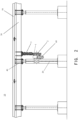
- FIG. 1 and Figure 2 show a front view and a side view of the photovoltaic tracking support 10 according to the invention, where a flat single-axis tracking support is taken as an example of the photovoltaic tracking support 10.
- a photovoltaic tracking support 10 comprises a column 20 and a shaft 30.
- the shaft is rotatably supported on the column 20, such as rotatably supported on the column 20 by a rotary support 40 shown in Figure 2 , the rotary support 40 can be for example a rotary bearing.
- a photovoltaic module 50 can be supported by the shaft 30.
- a plurality of columns 20 can be provided on an extending direction of the shaft 30, and three columns 20 are provided at equal distance along the extending direction of the shaft 30 in the figure, where the extending direction of the shaft 30 can be the south-north direction.
- the figures are merely examples and should not be construed as a limitation of the scope of the present disclosure.
- the alternatives in different embodiments can be combined appropriately.
- the photovoltaic tracking support 10 may comprises a transmission device 1.
- the transmission device 1 comprises a combined chain gear set 2 and a combined chain wheel set 3.
- the combined chain gear set 2 comprises a plurality of chain gears 4. It should be understood that the term 'a plurality of' means at least one or more than two, including two, three, four, five, etc..
- the combined chain gear set 2 comprises two chain gears 4, which are a first chain gear 41 and a second chain gear 42.
- the plurality of chain gears 4 are provided coaxially and in a staggered manner with each other.
- the term 'in a staggered manner' means that in the plurality of chain gears, the centreline of any one of the tooth tips on one chain gear does not overlap with (or be offset from or intersect with) the centreline of any one of the tooth tips on the other chain gear, or the centreline of any one of the concave parts on one chain gear does not overlap with the centreline of any one of the concave parts on the other chain gear.
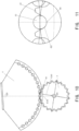
- the first chain gear 41 and the second chain gear 42 have a common central axis X4, the centreline C431 of the tooth tip 431 on the first chain gear 41 intersects with the centreline C432 of the tooth tip 432 on the second chain gear 42.
- Figure 3 to Figure 5 also show the concave part 441 on the first chain gear 41 and the centreline C441 of the concave part 441, the concave part 442 on the second chain gear 42 and the centreline C442 of the concave part 442.
- the term 'the centreline C431 of the tooth tip 431' refers to the connection line between the top of the tooth tip 431 and a centre of rotation 04 (a projection point of the central axis X4 on the plane) on a plane perpendicular to the central axis X4, or the extending line of the connection line, as shown in Figure 3 .
- the term 'the centreline C441 of the concave part 441' refers to the connection line between the bottom of the concave part 441 and the centre of rotation 04 on the plane perpendicular to the central axis X4, or the extending line of the connection line, as shown in Figure 3 .
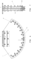
- the combined chain wheel set 3 comprises a plurality of chain wheels 5.
- the plurality of chain wheels 5 are provided coaxially and in one-to-one correspondence with the plurality of chain gears 4 mentioned above respectively.
- the combined chain gear set 2 comprises two chain gears 4, thus in the embodiment shown in Figure 6 and Figure 7 , correspondingly, the combined chain wheel set 3 comprises two chain wheels, which are a first chain wheel 51 and a second chain wheel 52 meshed with the first chain gear 41 and the second chain gear 42 respectively for transmission.
- the first chain wheel 51 and the second chain wheel 52 have a common central axis, which is projected on a vertical plane as a centre of rotation 05, as shown in Figure 6 .
- the first chain gear 41 and the second chain gear 42 are provided in the staggered manner, and the first chain wheel 51 and the second chain wheel 52 meshed with them respectively for transmission are also provided in the staggered manner.
- One of the combined chain gear set 2 and the combined chain wheel set 3 mentioned above is provided rotatably on the column 20, the other one is connected to the shaft 30.
- the combined chain gear set 2 is the one provided rotatably on the column 20, and the combined chain wheel set 3 is the other one connected to the shaft 30.
- the gap between the meshing points of the chain gears 4 and the chain wheels 5 that are meshed for transmission or paired varies continuously, as shown in Figure 8 to Figure 11 .
- the chain gears 4 may refer to the first chain gear 41 or the second chain gear 42, etc.
- the chain wheels 5 may refer to the first chain wheel 51 or the second chain wheel 52, etc.
- any one of the tooth tips 43 on the chain gears 4 may refer to the tooth tips 431 on the first chain gear 41 or the tooth tips 432 on the second chain gear 42, etc.
- any one of the concave parts 44 on the chain gears 4 may refer to the concave part 441 on the first chain gear 41 or the concave part 442 on the second chain gear 42, etc.
- the centreline C43 of the tooth tip 43 may refer to the centreline C431 of the tooth tip 431 on the first chain gear 41 or the centreline C432 of the tooth tip 432 on the second chain gear 42, etc.
- the centreline C44 of the concave part 44 may refer to the centreline C441 of the concave part 441 on the first chain gear 41 or the centreline C442 of the concave part 442 on the second chain gear 42, etc.
- a chain pin 53 on the chain wheel 5 may refer to the chain pin 531 on the first chain wheel 51 or the chain pin 532 on the second chain wheel 52, etc. correspondingly.
- connection line L45 between the centres of the chain gear 4 and the chain wheel 5 is the connection line between the centre of rotation 04 of the chain gear 4 and the centre of rotation 05 of the chain wheel 5.
- the size and the variation of the gap between the meshing points of the chain gear 4 and the chain wheel 5 should be as small as possible.
- the transmission device 1 mentioned above is provided with two pairs of chain wheels (the first chain gear 41 and the first chain wheel 51 paired, the second chain gear 42 and the second chain wheel 52 paired) or more pairs of chain wheels that are combined together and arranged in the staggered manner (or staggered combination), with the relay transmission method, when the gap between the meshing points of one pair of chain wheel (for example the first chain gear 41 and the first chain wheel 51) is the largest, the gap between the meshing points of the other pair of chain wheel (for example the second chain gear 42 and the second chain wheel 52) is not the largest, thereby reducing the overall size of the gap of the chain wheel transmission and reducing the variation of the gap, and improving the ability of the photovoltaic tracking support to resist swinging due to the strong wind, improving the working performance of the chain wheel transmission such as in the outdoor condition without grease lubrication, improving the service life of the transmission device greatly.
- the combined chain gear set 2 comprises the first chain gear 41 and the second chain gear 42, preferably, the centreline C431 of any one of the tooth tips 431 on the first chain gear 41 overlaps with the centreline C442 of any one of the concave parts 442 on the second chain gear 42.
- the first chain wheel 51 and the second chain wheel 52 of the combined chain wheel set 3 can be provided in the same staggered manner, corresponding to the first chain gear 41 and the second chain gear 42.
- the centreline C431 of the tooth tip 431 on the first chain gear 41 overlaps with the connection line L45 between the centres of the first chain gear 41 and the first chain wheel 51
- the centreline C442 of any one of the concave parts 442 on the second chain gear 42 overlaps with the connection line L45 between the centres of the second chain gear 42 and the second chain wheel 52.
- the gap between the meshing points of the first pair of chain wheels is the largest
- the gap between the meshing points of second pair of chain wheels is the smallest (or nearly 0).
- the variation of the gap between the meshing points of the chain gear and the chain wheel can be controlled within a half cycle range, so the size and variation of the gap of the chain wheel transmission can be reduced significantly, thereby improving the ability of the photovoltaic tracking support 10 to resist swinging due to the strong wind greatly, and improving the working performance of the chain wheel transmission such as in the outdoor condition without grease lubrication effectively, improving the service life of the transmission device 1 greatly.
- the combined chain gear set 2 may comprise the first chain gear, the second chain gear and the third chain gear, the central angle corresponding to any two of the adjacent tooth tips on the first chain gear is divided into three equal portions by the centerline of any one of the tooth tips on the second chain gear and the centreline of any one of the tooth tips on the third chain gear.
- the chain gear 4 can be regarded as the first chain gear, the central angle ⁇ corresponding to the two adjacent tooth tips 43a, 43b is divided into three equal portions by the half-lines L2, L3, the second chain gear and the third chain gear can be provided in a staggered manner, the centerline of any one of the tooth tips on the second chain gear and the centreline of any one of the tooth tips on the third chain gear overlap with the half-lines L2, L3 respectively.
- the number of the combined chain wheels should not be too many, preferably two orthree pairs.
- the chain gear 4 and the chain wheel 5 mentioned above can be a complete circular wheel, or an incomplete sector wheel.
- whether to use a circular wheel or a sector wheel can be determined based on the working range of the corresponding working part. For example, if the working range of the working part is larger than a circle (including a circle), a circular wheel is generally used for the chain gear or the chain wheel; if the working range of the working part is less than a circle or even half a circle, a sector wheel is generally used for the chain gear or the chain wheel to reduce the weight.
- the angle of sector of the sector wheel can be designed to be larger than the angle of rotation corresponding to the working range of the working part. For example for the flat single-axis tracking support, the tracking range in the east-west direction of the photovoltaic tracking support generally does not exceed ⁇ 60° in the actual operation, so the actual capable tracking range may not exceed ⁇ 70°.
- the combined chain wheel set 3 is the other one connected to the shaft 30, the plurality of chain wheels 5 provided thereon are all sector wheels connected below the shaft 30, so that the plurality of chain wheels 5 will not interfere with the photovoltaic module 50 supported by the shaft 30.
- the combined chain gear set 2 is the other one connected to the shaft 30, the plurality of chain gears 4 provided thereon can also be all sector wheels.
- the combined chain gear set 2 is the one provided rotatably on the column 20, the plurality of chain gears 4 provided thereon are all sector wheels.
- the angle of rotation of the chain gear 4 in the form of a circular wheel is larger than the angle of rotation of the corresponding chain wheel 5 in the form of a sector wheel, and the transmission ratio is greater than 1.
- the radius of the reference circles of the plurality of chain gears 4 are the same, so as to ensure that the speed ratio of the corresponding pair of chain wheel is the same, realizing synchronous transmission.
- the number of teeth of the plurality of chain gears 4 are also the same, so as to achieve the ideal relay transmission mode.
- the chain gear 4 can be a sector wheel rather than a circular wheel, it should be understood that when a sector wheel is used for the chain gear 4, 'the number of teeth of the plurality of chain gears 4' refers to the number of teeth on the complete circle when the chain gears 4 in the form of a sector wheel is filled into a complete circular wheel.
- the configurations and dimensions of the plurality of chain gears 4 are completely the same.
- the plurality of chain gears 4 can be fixedly connected to each other.
- the plurality of chain wheels 5 can also be fixedly connected to each other.
- the first chain gear 41 and the second chain gear 42 are fixed in series by a coupling shaft 71 with a key groove inserted through the center and a key 72 inserted into the key groove provided on the coupling shaft 71 to prevent rotation.
- the first chain wheel 51 and the second chain wheel 52 are fixed in series by a fastener 81 such as a bolt.
- the plurality of chain gears 4 are provided with an axial gap between each other.
- an axial gap D4 is provided between the first chain gear 41 and the second chain gear 42.
- the photovoltaic tracking support 10 further comprises a driving unit 60 for driving the rotation of the combined chain gear set 2 that is taken as an example of the one mention above.
- the driving unit 60 for example can be a rotary speed reduction motor, comprising a rotary bearing, a speed reducer and a motor.
- the rotary speed reduction motor that is taken as an example of the driving unit 60 is mounted on the column 20, and the combined chain gear set 2 is mounted on a rotating output end of the rotary speed reduction motor, the plurality of chain gears 4 of the combined chain gear set 2 can be fixedly connected together, so that the driving unit 60 can drive the plurality of chain gears 4 of the combined chain gear set 2 to rotate synchronously, thereby driving the plurality of chain wheels 5 of the combined chain wheel set 3 fully meshed with to rotate synchronously. Since the combined chain wheel set 3 is mounted on the shaft 30, the shaft 30 and the photovoltaic module 50 supported thereon can be driven to rotate synchronously.
- the driving device comprises the driving unit 60 and the transmission device 1, the rotary speed reduction motor that is taken as an example of the driving unit 60 is controlled to rotate in the forward and reverse directions, so the photovoltaic tracking support 10 can track and drive according to the change of solar azimuth angle.
- using the above transmission device 1 enables that the specification of the driving unit 60 such as the rotary speed reduction motor selected can be smaller when the photovoltaic tracking support 10 is used to drive the photovoltaic module 50 of the same capacity, and the cost and energy consumption can be relatively lower.
- the photovoltaic module 50 can still be mounted on the portion of the shaft 30 where the driving device is mounted, so that the mounting arrangement of the photovoltaic module 50 on the shaft 30 of the photovoltaic tracking support 10 can be more compact.
- the photovoltaic tracking support has been widely used.
- the transmission device mentioned above and the photovoltaic tracking support comprising the transmission device mentioned above will have a broad application prospect in the construction of photovoltaic power plants in the future.
Landscapes
- Engineering & Computer Science (AREA)
- Life Sciences & Earth Sciences (AREA)
- Sustainable Development (AREA)
- Physics & Mathematics (AREA)
- Sustainable Energy (AREA)
- Thermal Sciences (AREA)
- Chemical & Material Sciences (AREA)
- Combustion & Propulsion (AREA)
- Mechanical Engineering (AREA)
- General Engineering & Computer Science (AREA)
- Devices For Conveying Motion By Means Of Endless Flexible Members (AREA)
- Gears, Cams (AREA)
Applications Claiming Priority (2)
| Application Number | Priority Date | Filing Date | Title |
|---|---|---|---|
| CN202020672094.8U CN211557214U (zh) | 2020-04-27 | 2020-04-27 | 光伏跟踪支架及其传动装置 |
| PCT/CN2021/088627 WO2021218732A1 (zh) | 2020-04-27 | 2021-04-21 | 光伏跟踪支架及其传动装置 |
Publications (2)
| Publication Number | Publication Date |
|---|---|
| EP4145698A1 true EP4145698A1 (de) | 2023-03-08 |
| EP4145698A4 EP4145698A4 (de) | 2024-05-29 |
Family
ID=72496859
Family Applications (1)
| Application Number | Title | Priority Date | Filing Date |
|---|---|---|---|
| EP21796031.9A Pending EP4145698A4 (de) | 2020-04-27 | 2021-04-21 | Fotovoltaische verfolgungshilfe und übertragungsvorrichtung dafür |
Country Status (4)
| Country | Link |
|---|---|
| US (2) | US11901856B2 (de) |
| EP (1) | EP4145698A4 (de) |
| CN (1) | CN211557214U (de) |
| WO (1) | WO2021218732A1 (de) |
Families Citing this family (6)
| Publication number | Priority date | Publication date | Assignee | Title |
|---|---|---|---|---|
| CN211557214U (zh) * | 2020-04-27 | 2020-09-22 | 上海摩昆新能源科技有限公司 | 光伏跟踪支架及其传动装置 |
| CN112332764A (zh) * | 2020-10-19 | 2021-02-05 | 福建安泰新能源科技有限公司 | 一种光伏跟踪支架用新型传动装置 |
| US11863118B2 (en) | 2020-12-22 | 2024-01-02 | Sun And Steel Solar Llc | Bearing system for solar tracker |
| CN114489158A (zh) * | 2022-02-11 | 2022-05-13 | 杭州华鼎新能源有限公司 | 一种光伏自动跟踪集散控制系统 |
| US11946587B2 (en) * | 2022-03-01 | 2024-04-02 | Sun And Steel Solar Llc | Simple bearing for solar tracking |
| CN117134699B (zh) * | 2023-09-07 | 2024-04-12 | 上海摩昆新能源科技有限公司 | 一种支撑结构及光伏跟踪支架 |
Family Cites Families (14)
| Publication number | Priority date | Publication date | Assignee | Title |
|---|---|---|---|---|
| WO2004053356A1 (fr) * | 2002-12-09 | 2004-06-24 | Frank Muller Watchland S.A. | Engrenage a roues dentees |
| CN201802818U (zh) * | 2010-10-09 | 2011-04-20 | 洛阳北方玻璃技术股份有限公司 | 可变中心距传动齿轮装置 |
| JP6155140B2 (ja) | 2013-08-14 | 2017-06-28 | 有限会社グリテックスインターナショナルリミテッド | 太陽光を追尾する受光パネル駆動装置 |
| PT3108186T (pt) * | 2014-02-19 | 2021-06-02 | Array Tech Inc | Rastreador solar incorporando limitadores de torção |
| WO2016192766A1 (de) * | 2015-06-01 | 2016-12-08 | Habdank Pv-Montagesysteme Gmbh & Co. Kg | Nachführvorrichtung |
| CN107710570B (zh) * | 2015-06-17 | 2019-07-09 | 三菱电机株式会社 | 永磁电动机 |
| EP3482142A4 (de) * | 2016-07-08 | 2020-10-28 | Alion Energy, Inc. | Systeme und verfahren zur drehbaren montage und verriegelung von solarpaneelen |
| US10298172B2 (en) * | 2016-09-01 | 2019-05-21 | Sunpower Corporation | Photovoltaic module mounting assembly having a retainer |
| CN206429641U (zh) * | 2016-12-28 | 2017-08-22 | 昂华(上海)自动化工程股份有限公司 | 一种重负载高精度转台 |
| CN209959807U (zh) | 2019-04-22 | 2020-01-17 | 无锡先导智能装备股份有限公司 | 齿轮传动机构 |
| CN110247622B (zh) * | 2019-07-23 | 2024-01-30 | 上海摩昆新能源科技有限公司 | 光伏跟踪支架及其旋转减振装置 |
| CN209949041U (zh) | 2019-07-23 | 2020-01-14 | 上海摩昆新能源科技有限公司 | 光伏跟踪支架及其旋转减振装置 |
| CN211557214U (zh) | 2020-04-27 | 2020-09-22 | 上海摩昆新能源科技有限公司 | 光伏跟踪支架及其传动装置 |
| CN111431475A (zh) | 2020-04-27 | 2020-07-17 | 上海摩昆新能源科技有限公司 | 光伏跟踪支架及其传动装置 |
-
2020
- 2020-04-27 CN CN202020672094.8U patent/CN211557214U/zh active Active
-
2021
- 2021-04-21 WO PCT/CN2021/088627 patent/WO2021218732A1/zh unknown
- 2021-04-21 US US17/754,241 patent/US11901856B2/en active Active
- 2021-04-21 EP EP21796031.9A patent/EP4145698A4/de active Pending
-
2024
- 2024-01-03 US US18/403,617 patent/US20240154567A1/en active Pending
Also Published As
| Publication number | Publication date |
|---|---|
| WO2021218732A1 (zh) | 2021-11-04 |
| US20220294385A1 (en) | 2022-09-15 |
| US11901856B2 (en) | 2024-02-13 |
| CN211557214U (zh) | 2020-09-22 |
| EP4145698A4 (de) | 2024-05-29 |
| US20240154567A1 (en) | 2024-05-09 |
Similar Documents
| Publication | Publication Date | Title |
|---|---|---|
| EP4145698A1 (de) | Fotovoltaische verfolgungshilfe und übertragungsvorrichtung dafür | |
| US8920278B2 (en) | Gear transmission and photovoltaic power-generating apparatus using the gear transmission | |
| US20190390736A1 (en) | Thickness-variable transmission structure for robot joint | |
| CN209543148U (zh) | 一种双拨轮传动光伏跟踪系统及包含其的光伏系统 | |
| CN201420836Y (zh) | 类摆线轮与行星轮复合结构的减速机 | |
| CN111765236A (zh) | 平单轴串联多点同步驱动跟踪减速机 | |
| CN111431475A (zh) | 光伏跟踪支架及其传动装置 | |
| CN210839447U (zh) | 平单轴联动太阳能跟踪系统 | |
| CN1068664C (zh) | 复式滚动活齿传动 | |
| CN102352810A (zh) | 一种叶片随位变角的叶轮机 | |
| CN108044645B (zh) | 一种变厚机器人关节传动结构 | |
| CN215059231U (zh) | 一种新型多点驱动跟踪用回转减速机 | |
| CN210510165U (zh) | 一种一体式定日镜传动机构 | |
| CN212657193U (zh) | 蜗杆转向式多点驱动跟踪用回转减速机 | |
| CN202118099U (zh) | 一种微型行星齿轮电动滚筒 | |
| CN212657209U (zh) | 平单轴串联多点同步驱动跟踪减速机 | |
| CN201075853Y (zh) | 机械式太阳光跟踪装置 | |
| CN217328304U (zh) | 一种两级摆线减速器 | |
| CN1837645A (zh) | 节能增力传动装置 | |
| CN205503872U (zh) | 一种滚柱活齿减速器 | |
| CN215806044U (zh) | 一种立式系列回转减速机 | |
| CN220770085U (zh) | 一种双支撑行星减速器 | |
| CN221762583U (zh) | 一种带有轴向输入轴的立式回转减速机 | |
| CN216951561U (zh) | 进口摆线针轮减速器摆线轮损坏的维修结构 | |
| CN220082082U (zh) | 少齿差减速器三偏心轴 |
Legal Events
| Date | Code | Title | Description |
|---|---|---|---|
| STAA | Information on the status of an ep patent application or granted ep patent |
Free format text: STATUS: THE INTERNATIONAL PUBLICATION HAS BEEN MADE |
|
| PUAI | Public reference made under article 153(3) epc to a published international application that has entered the european phase |
Free format text: ORIGINAL CODE: 0009012 |
|
| STAA | Information on the status of an ep patent application or granted ep patent |
Free format text: STATUS: REQUEST FOR EXAMINATION WAS MADE |
|
| 17P | Request for examination filed |
Effective date: 20221122 |
|
| AK | Designated contracting states |
Kind code of ref document: A1 Designated state(s): AL AT BE BG CH CY CZ DE DK EE ES FI FR GB GR HR HU IE IS IT LI LT LU LV MC MK MT NL NO PL PT RO RS SE SI SK SM TR |
|
| DAV | Request for validation of the european patent (deleted) | ||
| DAX | Request for extension of the european patent (deleted) | ||
| A4 | Supplementary search report drawn up and despatched |
Effective date: 20240426 |
|
| RIC1 | Information provided on ipc code assigned before grant |
Ipc: F24S 30/425 20180101ALI20240422BHEP Ipc: F16H 1/20 20060101ALI20240422BHEP Ipc: H02S 20/32 20140101AFI20240422BHEP |