EP4137854B1 - Interstitieller vertiefter freitragender verriegelungsmechanismus für faseroptische und elektrische verbinder - Google Patents
Interstitieller vertiefter freitragender verriegelungsmechanismus für faseroptische und elektrische verbinder Download PDFInfo
- Publication number
- EP4137854B1 EP4137854B1 EP22190558.1A EP22190558A EP4137854B1 EP 4137854 B1 EP4137854 B1 EP 4137854B1 EP 22190558 A EP22190558 A EP 22190558A EP 4137854 B1 EP4137854 B1 EP 4137854B1
- Authority
- EP
- European Patent Office
- Prior art keywords
- connector assembly
- backshell
- latch
- plug housing
- contacts
- Prior art date
- Legal status (The legal status is an assumption and is not a legal conclusion. Google has not performed a legal analysis and makes no representation as to the accuracy of the status listed.)
- Active
Links
Images




Classifications
-
- G—PHYSICS
- G02—OPTICS
- G02B—OPTICAL ELEMENTS, SYSTEMS OR APPARATUS
- G02B6/00—Light guides; Structural details of arrangements comprising light guides and other optical elements, e.g. couplings
- G02B6/24—Coupling light guides
- G02B6/36—Mechanical coupling means
- G02B6/38—Mechanical coupling means having fibre to fibre mating means
- G02B6/3807—Dismountable connectors, i.e. comprising plugs
- G02B6/3869—Mounting ferrules to connector body, i.e. plugs
- G02B6/387—Connector plugs comprising two complementary members, e.g. shells, caps, covers, locked together
-
- G—PHYSICS
- G02—OPTICS
- G02B—OPTICAL ELEMENTS, SYSTEMS OR APPARATUS
- G02B6/00—Light guides; Structural details of arrangements comprising light guides and other optical elements, e.g. couplings
- G02B6/24—Coupling light guides
- G02B6/36—Mechanical coupling means
- G02B6/38—Mechanical coupling means having fibre to fibre mating means
- G02B6/3807—Dismountable connectors, i.e. comprising plugs
- G02B6/381—Dismountable connectors, i.e. comprising plugs of the ferrule type, e.g. fibre ends embedded in ferrules, connecting a pair of fibres
- G02B6/3826—Dismountable connectors, i.e. comprising plugs of the ferrule type, e.g. fibre ends embedded in ferrules, connecting a pair of fibres characterised by form or shape
- G02B6/3831—Dismountable connectors, i.e. comprising plugs of the ferrule type, e.g. fibre ends embedded in ferrules, connecting a pair of fibres characterised by form or shape comprising a keying element on the plug or adapter, e.g. to forbid wrong connection
-
- G—PHYSICS
- G02—OPTICS
- G02B—OPTICAL ELEMENTS, SYSTEMS OR APPARATUS
- G02B6/00—Light guides; Structural details of arrangements comprising light guides and other optical elements, e.g. couplings
- G02B6/24—Coupling light guides
- G02B6/36—Mechanical coupling means
- G02B6/40—Mechanical coupling means having fibre bundle mating means
- G02B6/406—Mechanical coupling means having fibre bundle mating means of the ferrule type, connecting a plurality of pairs of ferrules
-
- H—ELECTRICITY
- H01—ELECTRIC ELEMENTS
- H01R—ELECTRICALLY-CONDUCTIVE CONNECTIONS; STRUCTURAL ASSOCIATIONS OF A PLURALITY OF MUTUALLY-INSULATED ELECTRICAL CONNECTING ELEMENTS; COUPLING DEVICES; CURRENT COLLECTORS
- H01R13/00—Details of coupling devices of the kinds covered by groups H01R12/70 or H01R24/00 - H01R33/00
- H01R13/46—Bases; Cases
- H01R13/502—Bases; Cases composed of different pieces
- H01R13/506—Bases; Cases composed of different pieces assembled by snap action of the parts
-
- G—PHYSICS
- G02—OPTICS
- G02B—OPTICAL ELEMENTS, SYSTEMS OR APPARATUS
- G02B6/00—Light guides; Structural details of arrangements comprising light guides and other optical elements, e.g. couplings
- G02B6/24—Coupling light guides
- G02B6/36—Mechanical coupling means
- G02B6/38—Mechanical coupling means having fibre to fibre mating means
- G02B6/3807—Dismountable connectors, i.e. comprising plugs
- G02B6/381—Dismountable connectors, i.e. comprising plugs of the ferrule type, e.g. fibre ends embedded in ferrules, connecting a pair of fibres
- G02B6/3817—Dismountable connectors, i.e. comprising plugs of the ferrule type, e.g. fibre ends embedded in ferrules, connecting a pair of fibres containing optical and electrical conductors
-
- G—PHYSICS
- G02—OPTICS
- G02B—OPTICAL ELEMENTS, SYSTEMS OR APPARATUS
- G02B6/00—Light guides; Structural details of arrangements comprising light guides and other optical elements, e.g. couplings
- G02B6/24—Coupling light guides
- G02B6/36—Mechanical coupling means
- G02B6/38—Mechanical coupling means having fibre to fibre mating means
- G02B6/3807—Dismountable connectors, i.e. comprising plugs
- G02B6/381—Dismountable connectors, i.e. comprising plugs of the ferrule type, e.g. fibre ends embedded in ferrules, connecting a pair of fibres
- G02B6/3826—Dismountable connectors, i.e. comprising plugs of the ferrule type, e.g. fibre ends embedded in ferrules, connecting a pair of fibres characterised by form or shape
-
- G—PHYSICS
- G02—OPTICS
- G02B—OPTICAL ELEMENTS, SYSTEMS OR APPARATUS
- G02B6/00—Light guides; Structural details of arrangements comprising light guides and other optical elements, e.g. couplings
- G02B6/24—Coupling light guides
- G02B6/36—Mechanical coupling means
- G02B6/38—Mechanical coupling means having fibre to fibre mating means
- G02B6/3807—Dismountable connectors, i.e. comprising plugs
- G02B6/3887—Anchoring optical cables to connector housings, e.g. strain relief features
-
- G—PHYSICS
- G02—OPTICS
- G02B—OPTICAL ELEMENTS, SYSTEMS OR APPARATUS
- G02B6/00—Light guides; Structural details of arrangements comprising light guides and other optical elements, e.g. couplings
- G02B6/24—Coupling light guides
- G02B6/36—Mechanical coupling means
- G02B6/40—Mechanical coupling means having fibre bundle mating means
- G02B6/403—Mechanical coupling means having fibre bundle mating means of the ferrule type, connecting a pair of ferrules
Definitions
- This invention relates to the latching of fiber optic and electrical connectors and adapters, and securing the mated connections resulting therefrom.
- Latch-type connectors are commonly seen across the industry in both electrical and fiber optic connectors.
- electrical connectors include the RJ11 and RJ45 interfaces, while in the realm of fiber optics, the common LC and MPO types both use latches to result in a mechanically secure connection.
- Latches are usually preferred over electrical press-fit connectors, such as USB-A connector, because they provide visual, audible, and tactile feedback to the user when properly mated.
- a latch is necessary to provide sufficient and secure depth-of-mate to ensure physical contact upon which optical performance of the connection depends.
- a major drawback of traditional latch-type designs is that the latch is always placed outside the envelope of the contact pattern. This means that the inclusion of the latch mechanism increases the overall envelope of the connector interface, forcing it to become either wider or taller than the connector would otherwise need to be. As such, a mechanism which utilizes the space between contacts could achieve the advantages of a latch-type connection while simultaneously minimizing the overall size of the connector interface.
- US 2021/0191050 discloses a fiber optic connector port arrangement including at least one upper receptacle and at least one lower receptacle vertically aligned with the upper receptacle to form a column of receptacles, the column including a center divider that divides the at least one upper receptacle from the at least one lower receptacle.
- the center divider defines latching shoulders for mating with latches of both a connector to be mounted at the upper receptacle of the column and a connector to be mounted at the lower receptacle of the column.
- the present invention relates to a connector assembly as claimed in claim 1, a connector system as claimed in claim 17 and a method of connector assembly as claimed in claim 18.
- Embodiments of the inventive connectors and connector components described overcome disadvantages of traditional connectors, connector components, and attachment means, and allow more connectors to be used within a given space.
- the exemplary connectors discussed herein include a mechanism that does not increase the overall envelope of the connector interface, thereby necessitating less space for a proper connector by minimizing the overall size of the connector interface. Such reduction of the connector interface size allows a greater number of connectors to be used within a given space, as compared to traditional connectors.
- a connector plug comprised of a connector housing at the proximal end, a two-part backshell at the distal end, with a plurality of contacts housed within in a pre-defined contact pattern.
- Cantilever latching arms extend from the proximal end of the backshell. When mating with the receptacle, these latching arms depress into interstices between contact positions on the plug and snap into latching points located on the receptacle. Touch points are provided to enable the user to depress the latching arms and release the connector plug when required.
- the two parts of the backshell are identical and mate to each other hermaphroditically.
- an ergonomically-designed decoupler is added encircling the connector plug, which when pulled towards the distal end of the connector, cams over an angled surface on the latching arms, depressing them and releasing the connector plug.
- an exemplary connector assembly includes a plug housing including contacts.
- the plug housing defines a proximal end and a distal end.
- the connector assembly includes a backshell located at or near the distal end of the plug housing.
- the backshell includes a latching mechanism extending from a proximal end of the backshell. The latching mechanism is at least partially recessed into a complementary space formed in the plug housing.
- the contacts can include an array of 8 contacts.
- the backshell can include a first backshell half and a second backshell half.
- the first and second backshell halves can be identical (or substantially identical) and can be configured to engage relative to each other to form the backshell.
- the first and second backshell halves can assemble to one another hermaphroditically.
- the cantilever can include a press surface extending from the backshell, a ramp extending from the press surface, and the at least one latch extending from the ramp.
- the press surface can define a broad surface capable of being biased to lower the at least one latch deeper into the complementary space of the plug housing.
- the at least one latch can be configured to engage with a complementary latch point of a receptacle. Biasing the cantilever to lower the at least one latch deeper into the complementary space of the plug housing can disengage the at least one latch from the complementary latch point of the receptacle.
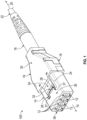
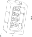
- Both plug assembly 100 from FIGS. 1 and 2 and plug assembly 110 from FIG. 3 are designed to mate to the exemplary receptacle 200 shown in FIG. 4 .
- the receptacle 200 provides front opening 50 to accept the proximal ends 10 and 10' of plug assemblies 100 and 110, respectively.
- Keyway 52 aligns with alignment key 38 of plug housing 14, ensuring contacts line up when the latches 28 snap into latch points 54.
- the latch points 54 define grooves or openings extending from the inner surface of the opening 50 at a position complementary to the latches 28 of the plug assembly 100, 110.
- Biasing of the latches 28 downward disengages the latches 28 from the latch points 54, allowing for removal of the plug assembly 100, 110 from the receptacle 200.
- the top and bottom edges/surfaces of opening 50 are completely smooth, as no vertical allowance is required to enable actuation and clearance of the latches 28 in that direction.
- the size of the opening 50 and the overall size of the receptacle 200 can thereby be kept at a minimum.
- traditional plug assemblies would necessitate additional features for latch clearance, expanding the overall envelope of the connector interface and increasing the overall size of the receptacle.
- FIG. 5 The simplicity of the latching mechanism is further illustrated by FIG. 5 , in which the plug assembly 100 has been mated to receptacle 200.
- the contacts have been removed from FIG. 5 for the sake of clarity. At this particular section point, there would be contacts in front of and behind the section plane, but open clearance inside the assembly where cantilever 24 would be depressed when mating and unmating plug assembly 100.
Landscapes
- Physics & Mathematics (AREA)
- General Physics & Mathematics (AREA)
- Optics & Photonics (AREA)
- Details Of Connecting Devices For Male And Female Coupling (AREA)
- Mechanical Coupling Of Light Guides (AREA)
Claims (18)
- Verbinderanordnung (100), umfassend:ein Steckergehäuse (14) mit Kontakten (12), wobei das Steckergehäuse (14) ein proximales Ende (10) und ein distales Ende (20) definiert; undein Endgehäuse (16), das sich am oder in der Nähe des distalen Endes (20) des Steckergehäuses (14) befindet;wobei das Endgehäuse (16) einen Feststellungsmechanismus einschließt, der sich von einem proximalen Ende des Endgehäuses (16) aus erstreckt und einen Ausleger (24) mit mindestens einer Feststellung (28) einschließt, die sich von dem proximalen Ende des Auslegers (24) aus erstreckt, und der Feststellungsmechanismus mindestens teilweise in einen komplementären Raum (37), der in dem Steckergehäuse (14) ausgebildet ist, eingelassen ist; undwobei in der mindestens teilweise eingelassenen Position des Feststellungsmechanismus die mindestens eine Feststellung (28) des Auslegers (24) in einem Zwischenraum zwischen den Kontakten (12) des Steckergehäuses (14) angeordnet ist.
- Verbinderanordnung (100) nach Anspruch 1, wobei die Kontakte (12) eine Anordnung von 8 Kontakten (12) einschließen.
- Verbinderanordnung (100) nach Anspruch 1, wobei das Endgehäuse (16) eine erste Endgehäusehälfte (16) und eine zweite Endgehäusehälfte (16) einschließt.
- Verbinderanordnung (100) nach Anspruch 3, wobei die erste und die zweite Endgehäusehälfte (16) identisch sind und so konfiguriert sind, dass sie relativ zueinander in Eingriff kommen, um das Endgehäuse (16) zu bilden.
- Verbinderanordnung (100) nach Anspruch 3, wobei die erste und die zweite Endgehäusehälfte (16) sich hermaphroditisch zusammensetzen.
- Verbinderanordnung (100) nach Anspruch 1, wobei der komplementäre Raum (37), der in dem Steckergehäuse (14) ausgebildet ist, eine eingelassene Nut oder eine Öffnung ist, die in einer oberen Oberfläche (36) des Steckergehäuses (14) ausgebildet ist und so konfiguriert ist, dass er mindestens teilweise den Feststellungsmechanismus des Endgehäuses (16) aufnimmt.
- Verbinderanordnung (100) nach Anspruch 1, wobei der Ausleger (24) eine Druckfläche (34), die sich von dem Endgehäuse (16) erstreckt, eine Rampe (32), die sich von der Druckfläche (34) erstreckt, und die mindestens eine Feststellung (28), die sich von der Rampe (32) erstreckt, einschließt.
- Verbinderanordnung (100) nach Anspruch 7, wobei die Druckfläche (34) eine breite Oberfläche definiert, die vorgespannt werden kann, um die mindestens eine Feststellung (28) tiefer in den komplementären Raum (37) des Steckergehäuses (14) abzusenken.
- Verbinderanordnung (100) nach Anspruch 7, wobei die mindestens eine Feststellung (28) so konfiguriert ist, dass sie einen komplementären Feststellungspunkt (54) einer Aufnahme (200) in Eingriff nimmt.
- Verbinderanordnung (100) nach Anspruch 9, wobei das Vorspannen des Auslegers (24), um die mindestens eine Feststellung (28) tiefer in den komplementären Raum (37) des Steckergehäuses (14) abzusenken, die mindestens eine Feststellung (28) von dem komplementären Feststellungspunkt (54) der Aufnahme (200) löst.
- Verbinderanordnung (100) nach Anspruch 8, umfassend einen Entkoppler (40), der verschiebbar über dem Steckergehäuse (14) und dem Endgehäuse (16) angeordnet ist.
- Verbinderanordnung (100) nach Anspruch 11, wobei das Verschieben des Entkopplers (40) über die Rampe (32) des Auslegers (24) die mindestens eine Feststellung (28) tiefer in den komplementären Raum (37) des Steckergehäuses (14) drückt und vorspannt, um die mindestens eine Feststellung (28) von einem komplementären Feststellungspunkt (54) einer Aufnahme (200) zu lösen.
- Verbinderanordnung (100) nach Anspruch 1, wobei die Kontakte (12) Glasfaser-Ferrulen sind.
- Verbinderanordnung (100) nach Anspruch 1, wobei die Kontakte (12) elektrische Kontakte sind.
- Verbinderanordnung (100) nach Anspruch 1, wobei die Kontakte (12) mindestens eine Glasfaser-Ferrule und mindestens einen elektrischen Kontakt einschließen.
- Verbinderanordnung (100) nach Anspruch 1, wobei der Feststellungsmechanismus eine Vielzahl von Auslegern (24) einschließt, wobei jeder der Ausleger (24) die mindestens eine Feststellung (28) einschließt, die am proximalen Ende des jeweiligen Auslegers (24) angeordnet ist.
- Verbindersystem, umfassend:eine Verbinderanordnung (100) nach einem der vorstehenden Ansprüche, undeine Aufnahme (200), die so konfiguriert ist, dass sie mindestens teilweise die Kontakte (12) der Verbinderanordnung (100) aufnimmt.
- Verfahren zum Verbinden einer Verbinderanordnung (100) nach einem der Ansprüche 1 bis 16, umfassend:elektrisches oder optisches Verbinden der Verbinderanordnung (100) mit einer Aufnahme (200); undDrücken des Feststellungsmechanismus weiter in den komplementären Raum (37), der im Steckergehäuse (14) ausgebildet ist, um die Verbinderanordnung (100) von der Aufnahme (200) zu lösen.
Applications Claiming Priority (1)
| Application Number | Priority Date | Filing Date | Title |
|---|---|---|---|
| US202163259856P | 2021-08-16 | 2021-08-16 |
Publications (3)
| Publication Number | Publication Date |
|---|---|
| EP4137854A1 EP4137854A1 (de) | 2023-02-22 |
| EP4137854B1 true EP4137854B1 (de) | 2024-11-27 |
| EP4137854C0 EP4137854C0 (de) | 2024-11-27 |
Family
ID=82939684
Family Applications (1)
| Application Number | Title | Priority Date | Filing Date |
|---|---|---|---|
| EP22190558.1A Active EP4137854B1 (de) | 2021-08-16 | 2022-08-16 | Interstitieller vertiefter freitragender verriegelungsmechanismus für faseroptische und elektrische verbinder |
Country Status (5)
| Country | Link |
|---|---|
| US (1) | US12158621B2 (de) |
| EP (1) | EP4137854B1 (de) |
| ES (1) | ES2999647T3 (de) |
| MX (1) | MX2022010028A (de) |
| PL (1) | PL4137854T3 (de) |
Families Citing this family (2)
| Publication number | Priority date | Publication date | Assignee | Title |
|---|---|---|---|---|
| US12523821B2 (en) | 2021-04-08 | 2026-01-13 | Commscope Technologies Llc | Telecommunications connector with latch release mechanism |
| US12158621B2 (en) * | 2021-08-16 | 2024-12-03 | Nest Technical Services, Inc. | Interstitial recessed cantilever latch mechanism for fiber optic and electrical connectors |
Family Cites Families (22)
| Publication number | Priority date | Publication date | Assignee | Title |
|---|---|---|---|---|
| NL1002956C2 (nl) * | 1996-04-26 | 1997-10-28 | Framatome Connectors Belgium | Multifiber connectorplug. |
| US5828804A (en) * | 1996-10-15 | 1998-10-27 | Panduit Corp. | Fiber optic connector system |
| JP3404621B2 (ja) * | 1998-11-10 | 2003-05-12 | ソニー株式会社 | 光コネクタ |
| JP3651311B2 (ja) * | 1999-05-26 | 2005-05-25 | ソニー株式会社 | 光コネクタ |
| US7281937B2 (en) | 2005-02-18 | 2007-10-16 | Molex Incorporated | Low profile latching connector |
| JP5271091B2 (ja) * | 2009-01-09 | 2013-08-21 | 日本コヴィディエン株式会社 | 内視鏡の接続構造 |
| US9709752B2 (en) * | 2011-05-19 | 2017-07-18 | Konica Minolta, Inc. | Optical connector plug, optical probe, and optical system |
| JP6073373B2 (ja) | 2012-02-07 | 2017-02-01 | スリーエム イノベイティブ プロパティズ カンパニー | ワイヤマウント電気コネクタ |
| US8678846B2 (en) | 2012-03-28 | 2014-03-25 | Tyco Electronics Corporation | Electrical connector with connector position assurance device |
| EP2700992B1 (de) | 2012-08-24 | 2019-08-07 | Ridgemount Technologies Limited | Faseroptischer Stecker |
| WO2014209671A2 (en) * | 2013-06-25 | 2014-12-31 | Corning Optical Communications LLC | Optical plug having a translating cover and a complimentary receptacle |
| US9494744B2 (en) | 2014-11-10 | 2016-11-15 | Corning Optical Communications LLC | Fiber optic connector having a main connector body and a plurality of removable sub-connectors |
| US20180003903A1 (en) * | 2016-06-29 | 2018-01-04 | Google Inc. | Cable Connector |
| US10185100B2 (en) | 2017-01-30 | 2019-01-22 | Senko Advanced Components, Inc | Modular connector and adapter assembly using a removable anchor device |
| US10663676B2 (en) * | 2017-05-25 | 2020-05-26 | Senko Advanced Components, Inc | Adjustable polarity fiber optic connector assemblies with push-pull tabs |
| WO2018226959A1 (en) * | 2017-06-07 | 2018-12-13 | Commscope Technologies Llc | Fiber optic adapter and cassette |
| US10281668B2 (en) | 2017-07-14 | 2019-05-07 | Senko Advanced Components, Inc. | Ultra-small form factor optical connectors |
| JP7107083B2 (ja) * | 2018-08-08 | 2022-07-27 | 住友電気工業株式会社 | 光コネクタ、及び光コネクタの製造方法 |
| US12158621B2 (en) * | 2021-08-16 | 2024-12-03 | Nest Technical Services, Inc. | Interstitial recessed cantilever latch mechanism for fiber optic and electrical connectors |
| CN114578490B (zh) * | 2022-03-11 | 2024-03-26 | 深圳市利诺威科技有限公司 | 一种带锁扣的hdmi光纤插头 |
| WO2023205045A1 (en) * | 2022-04-18 | 2023-10-26 | Ortronics, Inc. | System for fiber connector assembly |
| US12135459B2 (en) * | 2022-06-13 | 2024-11-05 | Legrand DPC, LLC | System for fiber connector assembly |
-
2022
- 2022-08-08 US US17/803,522 patent/US12158621B2/en active Active
- 2022-08-15 MX MX2022010028A patent/MX2022010028A/es unknown
- 2022-08-16 PL PL22190558.1T patent/PL4137854T3/pl unknown
- 2022-08-16 ES ES22190558T patent/ES2999647T3/es active Active
- 2022-08-16 EP EP22190558.1A patent/EP4137854B1/de active Active
Also Published As
| Publication number | Publication date |
|---|---|
| MX2022010028A (es) | 2023-02-17 |
| PL4137854T3 (pl) | 2025-03-31 |
| EP4137854C0 (de) | 2024-11-27 |
| ES2999647T3 (en) | 2025-02-26 |
| US20230050053A1 (en) | 2023-02-16 |
| US12158621B2 (en) | 2024-12-03 |
| EP4137854A1 (de) | 2023-02-22 |
Similar Documents
| Publication | Publication Date | Title |
|---|---|---|
| EP4137854B1 (de) | Interstitieller vertiefter freitragender verriegelungsmechanismus für faseroptische und elektrische verbinder | |
| US10777931B2 (en) | Modular electrical connector assembly | |
| US4960317A (en) | Wall outlet for a fiber optic connector assembly | |
| US4789351A (en) | Blind mating connector with snap ring insertion | |
| US9448370B2 (en) | Connector and connector assembly | |
| US6290527B1 (en) | Nippon telegraph and telephone corporation | |
| US8651749B2 (en) | Fiber optic interface with translatable ferrule device | |
| JP4990984B2 (ja) | 光ユニバーサルシリアルバス | |
| US8011948B2 (en) | Electrical connector assembly wth improved latching mechanism | |
| US4445750A (en) | Articulating fiber optic connectors with resilient mounting block | |
| US4927374A (en) | Modular electrical connector assembly | |
| US20020126960A1 (en) | Connector and receptacle containing a physical security feature | |
| US11852874B2 (en) | Optical communications connectors | |
| JP2017010755A (ja) | 雄型コネクタ及び雌型コネクタ並びにこれらのコネクタからなる電気コネクタ | |
| CN119563131A (zh) | Vsff连接器和适配器 | |
| US20250174931A1 (en) | Mutoa and quad floating connector | |
| EP1001289B1 (de) | Ausfallsicherer optischer Verbinder | |
| US20210263225A1 (en) | Optical receptacle and module and optical connector module using the same | |
| EP0364075B1 (de) | Steckvorrichtung für einen faseroptischen Stecker | |
| CN219085176U (zh) | 光通信连接器 | |
| EP2380243B1 (de) | Elektrische verbindungseinrichtung | |
| US20220196920A1 (en) | Delatching devices for fiber optic connectors | |
| TWI564727B (zh) | 集線器 | |
| CN220421033U (zh) | 电连接器组合及电连接器 | |
| KR20260023494A (ko) | 모듈형 멀티모달 커넥터 하우징 |
Legal Events
| Date | Code | Title | Description |
|---|---|---|---|
| PUAI | Public reference made under article 153(3) epc to a published international application that has entered the european phase |
Free format text: ORIGINAL CODE: 0009012 |
|
| STAA | Information on the status of an ep patent application or granted ep patent |
Free format text: STATUS: THE APPLICATION HAS BEEN PUBLISHED |
|
| AK | Designated contracting states |
Kind code of ref document: A1 Designated state(s): AL AT BE BG CH CY CZ DE DK EE ES FI FR GB GR HR HU IE IS IT LI LT LU LV MC MK MT NL NO PL PT RO RS SE SI SK SM TR |
|
| P01 | Opt-out of the competence of the unified patent court (upc) registered |
Effective date: 20230601 |
|
| STAA | Information on the status of an ep patent application or granted ep patent |
Free format text: STATUS: REQUEST FOR EXAMINATION WAS MADE |
|
| 17P | Request for examination filed |
Effective date: 20230822 |
|
| RBV | Designated contracting states (corrected) |
Designated state(s): AL AT BE BG CH CY CZ DE DK EE ES FI FR GB GR HR HU IE IS IT LI LT LU LV MC MK MT NL NO PL PT RO RS SE SI SK SM TR |
|
| REG | Reference to a national code |
Ref country code: DE Ref legal event code: R079 Free format text: PREVIOUS MAIN CLASS: G02B0006380000 Ipc: H01B0013320000 Ref document number: 602022008124 Country of ref document: DE |
|
| GRAP | Despatch of communication of intention to grant a patent |
Free format text: ORIGINAL CODE: EPIDOSNIGR1 |
|
| STAA | Information on the status of an ep patent application or granted ep patent |
Free format text: STATUS: GRANT OF PATENT IS INTENDED |
|
| RIC1 | Information provided on ipc code assigned before grant |
Ipc: G02B 6/38 20060101ALI20240524BHEP Ipc: H01B 13/32 20060101AFI20240524BHEP |
|
| INTG | Intention to grant announced |
Effective date: 20240624 |
|
| RIN1 | Information on inventor provided before grant (corrected) |
Inventor name: SMITH, WILLIAM M. Inventor name: SMITH, DANIEL M. |
|
| GRAS | Grant fee paid |
Free format text: ORIGINAL CODE: EPIDOSNIGR3 |
|
| GRAA | (expected) grant |
Free format text: ORIGINAL CODE: 0009210 |
|
| STAA | Information on the status of an ep patent application or granted ep patent |
Free format text: STATUS: THE PATENT HAS BEEN GRANTED |
|
| AK | Designated contracting states |
Kind code of ref document: B1 Designated state(s): AL AT BE BG CH CY CZ DE DK EE ES FI FR GB GR HR HU IE IS IT LI LT LU LV MC MK MT NL NO PL PT RO RS SE SI SK SM TR |
|
| REG | Reference to a national code |
Ref country code: GB Ref legal event code: FG4D |
|
| REG | Reference to a national code |
Ref country code: CH Ref legal event code: EP |
|
| REG | Reference to a national code |
Ref country code: DE Ref legal event code: R096 Ref document number: 602022008124 Country of ref document: DE |
|
| REG | Reference to a national code |
Ref country code: IE Ref legal event code: FG4D |
|
| U01 | Request for unitary effect filed |
Effective date: 20241129 |
|
| P04 | Withdrawal of opt-out of the competence of the unified patent court (upc) registered |
Free format text: CASE NUMBER: APP_64824/2024 Effective date: 20241207 |
|
| U07 | Unitary effect registered |
Designated state(s): AT BE BG DE DK EE FI FR IT LT LU LV MT NL PT RO SE SI Effective date: 20241211 |
|
| REG | Reference to a national code |
Ref country code: ES Ref legal event code: FG2A Ref document number: 2999647 Country of ref document: ES Kind code of ref document: T3 Effective date: 20250226 |
|
| PG25 | Lapsed in a contracting state [announced via postgrant information from national office to epo] |
Ref country code: HR Free format text: LAPSE BECAUSE OF FAILURE TO SUBMIT A TRANSLATION OF THE DESCRIPTION OR TO PAY THE FEE WITHIN THE PRESCRIBED TIME-LIMIT Effective date: 20241127 Ref country code: IS Free format text: LAPSE BECAUSE OF FAILURE TO SUBMIT A TRANSLATION OF THE DESCRIPTION OR TO PAY THE FEE WITHIN THE PRESCRIBED TIME-LIMIT Effective date: 20250327 |
|
| PG25 | Lapsed in a contracting state [announced via postgrant information from national office to epo] |
Ref country code: NO Free format text: LAPSE BECAUSE OF FAILURE TO SUBMIT A TRANSLATION OF THE DESCRIPTION OR TO PAY THE FEE WITHIN THE PRESCRIBED TIME-LIMIT Effective date: 20250227 |
|
| PG25 | Lapsed in a contracting state [announced via postgrant information from national office to epo] |
Ref country code: GR Free format text: LAPSE BECAUSE OF FAILURE TO SUBMIT A TRANSLATION OF THE DESCRIPTION OR TO PAY THE FEE WITHIN THE PRESCRIBED TIME-LIMIT Effective date: 20250228 |
|
| PG25 | Lapsed in a contracting state [announced via postgrant information from national office to epo] |
Ref country code: RS Free format text: LAPSE BECAUSE OF FAILURE TO SUBMIT A TRANSLATION OF THE DESCRIPTION OR TO PAY THE FEE WITHIN THE PRESCRIBED TIME-LIMIT Effective date: 20250227 |
|
| PG25 | Lapsed in a contracting state [announced via postgrant information from national office to epo] |
Ref country code: SM Free format text: LAPSE BECAUSE OF FAILURE TO SUBMIT A TRANSLATION OF THE DESCRIPTION OR TO PAY THE FEE WITHIN THE PRESCRIBED TIME-LIMIT Effective date: 20241127 |
|
| PG25 | Lapsed in a contracting state [announced via postgrant information from national office to epo] |
Ref country code: SK Free format text: LAPSE BECAUSE OF FAILURE TO SUBMIT A TRANSLATION OF THE DESCRIPTION OR TO PAY THE FEE WITHIN THE PRESCRIBED TIME-LIMIT Effective date: 20241127 |
|
| PG25 | Lapsed in a contracting state [announced via postgrant information from national office to epo] |
Ref country code: CZ Free format text: LAPSE BECAUSE OF FAILURE TO SUBMIT A TRANSLATION OF THE DESCRIPTION OR TO PAY THE FEE WITHIN THE PRESCRIBED TIME-LIMIT Effective date: 20241127 |
|
| U20 | Renewal fee for the european patent with unitary effect paid |
Year of fee payment: 4 Effective date: 20250827 |
|
| PLBE | No opposition filed within time limit |
Free format text: ORIGINAL CODE: 0009261 |
|
| STAA | Information on the status of an ep patent application or granted ep patent |
Free format text: STATUS: NO OPPOSITION FILED WITHIN TIME LIMIT |
|
| REG | Reference to a national code |
Ref country code: CH Ref legal event code: L10 Free format text: ST27 STATUS EVENT CODE: U-0-0-L10-L00 (AS PROVIDED BY THE NATIONAL OFFICE) Effective date: 20251008 |
|
| PGFP | Annual fee paid to national office [announced via postgrant information from national office to epo] |
Ref country code: ES Payment date: 20250901 Year of fee payment: 4 |
|
| PGFP | Annual fee paid to national office [announced via postgrant information from national office to epo] |
Ref country code: PL Payment date: 20250822 Year of fee payment: 4 |
|
| 26N | No opposition filed |
Effective date: 20250828 |
|
| REG | Reference to a national code |
Ref country code: CH Ref legal event code: H13 Free format text: ST27 STATUS EVENT CODE: U-0-0-H10-H13 (AS PROVIDED BY THE NATIONAL OFFICE) Effective date: 20260324 |
|
| PG25 | Lapsed in a contracting state [announced via postgrant information from national office to epo] |
Ref country code: MC Free format text: LAPSE BECAUSE OF FAILURE TO SUBMIT A TRANSLATION OF THE DESCRIPTION OR TO PAY THE FEE WITHIN THE PRESCRIBED TIME-LIMIT Effective date: 20241127 |
|
| PG25 | Lapsed in a contracting state [announced via postgrant information from national office to epo] |
Ref country code: CH Free format text: LAPSE BECAUSE OF NON-PAYMENT OF DUE FEES Effective date: 20250831 |