EP4137828B1 - Apparatus and method for testing insulated high voltage devices - Google Patents
Apparatus and method for testing insulated high voltage devices Download PDFInfo
- Publication number
- EP4137828B1 EP4137828B1 EP22182995.5A EP22182995A EP4137828B1 EP 4137828 B1 EP4137828 B1 EP 4137828B1 EP 22182995 A EP22182995 A EP 22182995A EP 4137828 B1 EP4137828 B1 EP 4137828B1
- Authority
- EP
- European Patent Office
- Prior art keywords
- high voltage
- conductive fibers
- under test
- resiliently compressible
- insulated high
- Prior art date
- Legal status (The legal status is an assumption and is not a legal conclusion. Google has not performed a legal analysis and makes no representation as to the accuracy of the status listed.)
- Active
Links
Images


Classifications
-
- G—PHYSICS
- G01—MEASURING; TESTING
- G01R—MEASURING ELECTRIC VARIABLES; MEASURING MAGNETIC VARIABLES
- G01R31/00—Arrangements for testing electric properties; Arrangements for locating electric faults; Arrangements for electrical testing characterised by what is being tested not provided for elsewhere
- G01R31/12—Testing dielectric strength or breakdown voltage ; Testing or monitoring effectiveness or level of insulation, e.g. of a cable or of an apparatus, for example using partial discharge measurements; Electrostatic testing
- G01R31/1227—Testing dielectric strength or breakdown voltage ; Testing or monitoring effectiveness or level of insulation, e.g. of a cable or of an apparatus, for example using partial discharge measurements; Electrostatic testing of components, parts or materials
- G01R31/1263—Testing dielectric strength or breakdown voltage ; Testing or monitoring effectiveness or level of insulation, e.g. of a cable or of an apparatus, for example using partial discharge measurements; Electrostatic testing of components, parts or materials of solid or fluid materials, e.g. insulation films, bulk material; of semiconductors or LV electronic components or parts; of cable, line or wire insulation
- G01R31/1272—Testing dielectric strength or breakdown voltage ; Testing or monitoring effectiveness or level of insulation, e.g. of a cable or of an apparatus, for example using partial discharge measurements; Electrostatic testing of components, parts or materials of solid or fluid materials, e.g. insulation films, bulk material; of semiconductors or LV electronic components or parts; of cable, line or wire insulation of cable, line or wire insulation, e.g. using partial discharge measurements
-
- G—PHYSICS
- G01—MEASURING; TESTING
- G01R—MEASURING ELECTRIC VARIABLES; MEASURING MAGNETIC VARIABLES
- G01R31/00—Arrangements for testing electric properties; Arrangements for locating electric faults; Arrangements for electrical testing characterised by what is being tested not provided for elsewhere
- G01R31/12—Testing dielectric strength or breakdown voltage ; Testing or monitoring effectiveness or level of insulation, e.g. of a cable or of an apparatus, for example using partial discharge measurements; Electrostatic testing
- G01R31/16—Construction of testing vessels; Electrodes therefor
-
- G—PHYSICS
- G01—MEASURING; TESTING
- G01R—MEASURING ELECTRIC VARIABLES; MEASURING MAGNETIC VARIABLES
- G01R31/00—Arrangements for testing electric properties; Arrangements for locating electric faults; Arrangements for electrical testing characterised by what is being tested not provided for elsewhere
- G01R31/327—Testing of circuit interrupters, switches or circuit-breakers
- G01R31/3271—Testing of circuit interrupters, switches or circuit-breakers of high voltage or medium voltage devices
- G01R31/3272—Apparatus, systems or circuits therefor
Definitions
- This patent application is directed to an apparatus and method for testing devices used in a high voltage application (e.g., over 200 volts), particularly to an apparatus and method for testing the integrity of insulation of a high voltage device.
- a high voltage application e.g., over 200 volts
- High voltage electrical devices such as bus bars, wiring harnesses, or a combination thereof are preferably tested while energized with high voltage in contact with a ground plane to verify the integrity and adequacy of the electrical insulation on the device and ensure that no electrical arcs are generated due to insulation defects.
- a first example test apparatus includes machined metal plates acting as ground planes which surround the device under test.
- the metal plates are specially shaped to conform with the particular geometry of the device under test. Because these metal plates are customized for each device this first example test apparatus has the drawbacks of requiring separate ground planes that are specially configured for each unique device configuration under test along with the manufacturing costs and time for making each ground plane, and changes to the ground planes driven by engineering changes during the design cycle of the device under test.
- a second example test apparatus includes a chamber containing metal ball chains connected to ground that are arranged over and under the device under test. Since the metal ball chains under the device are noncompressible, this second example test apparatus is not well suited for inflexible devices, such as bus bars.
- a third example test apparatus is a metallic vacuum chamber in which the device under test is placed. The vacuum in the chamber increases the arc distance. This third example test apparatus has the drawbacks of requiring a sealed interface to test the device. The pneumatic features of the third example test apparatus have high costs for design, integration and maintenance. In addition, certain devices under test are not capable of withstanding the differential pressure needed.
- a fourth example test apparatus is a wand or cuff that replaces the ambient air around the device under test with an inert gas. This fourth example test apparatus is designed for manual use and has low test repeatability and therefore is unsuitable for regular high-volume production use.
- an apparatus for testing insulated high voltage devices includes a first ground plane connected to a reference voltage potential having a first plurality of resiliently compressible conductive fibers extending therefrom and a second ground plane connected to the reference voltage potential having a second plurality of resiliently compressible conductive fibers extending therefrom.
- the first and second ground planes are arranged to receive an insulated high voltage device under test connected to a voltage potential greater or less than the reference voltage potential between them and configured such that at least a portion of the first and second pluralities of resiliently compressible conductive fibers are in compressive contact with the insulated high voltage device under test.
- the first and second pluralities of resiliently compressible conductive fibers are formed carbon loaded convoluted expanded polymer foam material
- the first and second pluralities of resiliently compressible conductive fibers are formed of metallic materials.
- the first and second pluralities of resiliently compressible conductive fibers form spiral shapes.
- the first and second pluralities of resiliently compressible conductive fibers are formed of a coarse stainless steel wool, copper wool, or brass wool material.
- the first ground plane is connected to the second ground plane by an articulating hinge.
- the reference voltage potential is a ground potential and wherein the voltage potential of the insulated high voltage device under test is at least 200 volts greater than the ground potential.
- the apparatus further comprises an electrical connector electrically attaching the insulated high voltage device under test to the voltage potential that is disposed within an insulative shroud.
- the electrical connector is configured to receive an uninsulated portion of the insulated high voltage device under test within the insulative shroud.
- the electrical connector is a first electrical connector
- the apparatus further comprises a second electrical connector electrical attaching the insulated high voltage device under test to the voltage potential at a different location on the insulated high voltage device under test.
- a method of testing insulated high voltage devices includes the steps of: providing a first ground plane having a first plurality of resiliently compressible conductive fibers extending therefrom and a second ground plane having a second plurality of resiliently compressible conductive fibers extending therefrom, arranging the insulated high voltage device in contact with at least a portion of the resiliently compressible conductive fibers of the ground planes, connecting the first and second ground planes to a reference voltage potential, and connecting an insulated high voltage device under test to a voltage potential greater or less than the reference voltage potential.
- the method further includes the step of forming the first and second pluralities of resiliently compressible conductive fibers into spiral shapes.
- the method further includes the step of forming the first and second pluralities of resiliently compressible conductive fibers from a coarse stainless steel wool, copper wool, or brass wool material.
- the reference voltage potential is a ground potential and the voltage potential of the insulated high voltage device under test is at least 200 volts greater than the ground potential.
- the method further includes the steps of providing an electrical connector within an insulative shroud and electrically attaching the insulated high voltage device under test to the voltage potential via the electrical connector.
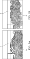
- the test apparatus 10 illustrated in Fig. 1 has a first ground plane, hereinafter referred to as the upper ground plane 12 that is connected to a reference voltage potential 14 e.g., ground potential.
- the upper ground plane 12 has a first plurality of resiliently compressible conductive fibers 16 extending from an upper ground plate 18.
- the test apparatus 10 also has a second ground plane, hereinafter referred to as the lower ground plane 20 that is also connected to the same reference voltage potential 14.
- the lower ground plane 20 has a second plurality of resiliently compressible conductive fibers 22 that extend from a lower ground plate 24.
- the upper and lower ground planes 12, 20 are arranged so as to receive an insulated high voltage device under test 2, such as an insulated bus bar, insulated cable, or insulated wiring harness between them.
- the device under test 2 is connected to a test voltage potential 26 that is greater or less than the reference voltage potential 14.
- the difference between the test voltage potential 26 and the reference voltage potential 14 may be at least 200 volts.
- the reference voltage potential 14 is preferably at ground potential and the test voltage potential 26 is greater than the ground potential.
- the upper ground plate 18 may have a planar configuration while the lower ground plate 24 may have a box-like configuration.
- the upper and lower ground planes 12, 20 are configured such that at least a portion of the first and second pluralities of resiliently compressible conductive fibers 16, 22 are in compressive contact with the device under test 2 as shown in Fig. 2B .
- the first and second pluralities of resiliently compressible conductive fibers 16, 22 are formed of metallic materials, such as a coarse metallic mesh or a coarse stainless steel wool, copper wool, or brass wool material.
- the first and second pluralities of resiliently compressible conductive fibers 16, 22 may be formed on a carbon loaded convoluted expanded polymer foam material, such as a convoluted foam absorber MF32-0002-00 manufactured by MAST Technologies of San Diego, California, USA.
- the first and second pluralities of resiliently compressible conductive fibers 16, 22 form spiral spring-like shapes as best shown in Figs 2A, 2B .
- spiral spring-like shaped fibers are then arranged into a spherical shape and electrically and mechanically attached to the upper and lower ground plates 18, 24.
- These spiral shaped fibers are arranged into a spherical shape, they have been found to provide a large number of electrical contact points between the upper and lower ground planes 12, 20 and the device under test 2 as well as provide the resiliency to successfully test devices having different shapes. This is beneficial because this allows the test apparatus 10 to accommodate devices under test 2 of differing design, e.g., a bus bar vs. a wire cable, or devices under test having different shapes e.g., two flexible wiring harnesses having the same configuration but different shapes.
- the upper and lower ground plates 18, 24 are formed of sheets of a conductive metal, such as copper, aluminum, or stainless steel.
- the upper ground plane 12 is connected to the lower ground plane 20 by an articulating hinge 28.
- This articulating hinge 28 allows the device under test 2 to be laid on the lower ground plane 20, thereby putting the device under test 2 in contact with the lower ground plane 20 as shown in Fig. 2A and then allows the upper ground plane 12 to be moved into a position in which the upper ground plane 12 also contacts the device under test 2 and compresses the first and second pluralities of resiliently compressible conductive fibers 16, 22 as shown in Fig. 2B .
- the apparatus further includes a first electrical connector 30 shown in Fig. 3 that is disposed within an insulative shroud 32 that electrically attaches the device under test 2 to the test voltage potential 26 and may further include a second electrical connector electrical 30of the same design attaching the voltage device under test 2 to the test voltage potential 26 at a different location, e.g., an opposite end of the device under test as shown in Fig. 1 .
- the first and second electrical connectors 30 are configured to receive an uninsulated portion of the voltage device under test 2 within the insulative shroud 32.
- the apparatus also includes additional electrical connectors (not shown) attaching the upper and lower ground planes to the reference potential.
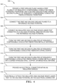
- Fig. 4 shows a flow chart of a method 100 of testing insulated high voltage devices that may be applied to the test apparatus 10 described above.
- the method 100 includes the following steps:
- the method 100 may further include the step of connecting the first ground plane 12 to the second ground plane 20 by an articulating hinge 28.
- 'one or more' includes a function being performed by one element, a function being performed by more than one element, e.g., in a distributed fashion, several functions being performed by one element, several functions being performed by several elements, or any combination of the above.
- first, second, etc. are, in some instances, used herein to describe various elements, these elements should not be limited by these terms. These terms are only used to distinguish one element from another.
- a first contact could be termed a second contact, and, similarly, a second contact could be termed a first contact, without departing from the scope of the various described embodiments.
- the first contact and the second contact are both contacts, but they are not the same contact.
- the term “if' is, optionally, construed to mean “when” or “upon” or “in response to determining” or “in response to detecting,” depending on the context.
- the phrase “if it is determined” or “if [a stated condition or event] is detected” is, optionally, construed to mean “upon determining” or “in response to determining” or “upon detecting [the stated condition or event]” or “in response to detecting [the stated condition or event],” depending on the context.
Landscapes
- Physics & Mathematics (AREA)
- General Physics & Mathematics (AREA)
- Testing Electric Properties And Detecting Electric Faults (AREA)
- Tests Of Electronic Circuits (AREA)
- Testing Relating To Insulation (AREA)
Description
- This patent application is directed to an apparatus and method for testing devices used in a high voltage application (e.g., over 200 volts), particularly to an apparatus and method for testing the integrity of insulation of a high voltage device.
- High voltage electrical devices, such as bus bars, wiring harnesses, or a combination thereof are preferably tested while energized with high voltage in contact with a ground plane to verify the integrity and adequacy of the electrical insulation on the device and ensure that no electrical arcs are generated due to insulation defects.
- Prior means for performing such tests have involved various apparatuses and methods. A first example test apparatus includes machined metal plates acting as ground planes which surround the device under test. The metal plates are specially shaped to conform with the particular geometry of the device under test. Because these metal plates are customized for each device this first example test apparatus has the drawbacks of requiring separate ground planes that are specially configured for each unique device configuration under test along with the manufacturing costs and time for making each ground plane, and changes to the ground planes driven by engineering changes during the design cycle of the device under test. A second example test apparatus includes a chamber containing metal ball chains connected to ground that are arranged over and under the device under test. Since the metal ball chains under the device are noncompressible, this second example test apparatus is not well suited for inflexible devices, such as bus bars. A third example test apparatus is a metallic vacuum chamber in which the device under test is placed. The vacuum in the chamber increases the arc distance. This third example test apparatus has the drawbacks of requiring a sealed interface to test the device. The pneumatic features of the third example test apparatus have high costs for design, integration and maintenance. In addition, certain devices under test are not capable of withstanding the differential pressure needed. A fourth example test apparatus is a wand or cuff that replaces the ambient air around the device under test with an inert gas. This fourth example test apparatus is designed for manual use and has low test repeatability and therefore is unsuitable for regular high-volume production use.
- Publications
US 2014/266284 A1 ,US 2009/102486 A1 ,US 2016/370415 A1 ,US 4 392 104 A ,US 2016/282403 A1 andGB 1 318 793 A - According to one or more aspects of the present disclosure, an apparatus for testing insulated high voltage devices includes a first ground plane connected to a reference voltage potential having a first plurality of resiliently compressible conductive fibers extending therefrom and a second ground plane connected to the reference voltage potential having a second plurality of resiliently compressible conductive fibers extending therefrom. The first and second ground planes are arranged to receive an insulated high voltage device under test connected to a voltage potential greater or less than the reference voltage potential between them and configured such that at least a portion of the first and second pluralities of resiliently compressible conductive fibers are in compressive contact with the insulated high voltage device under test.
- In one or more embodiments of the apparatus according to the previous paragraph, the first and second pluralities of resiliently compressible conductive fibers are formed carbon loaded convoluted expanded polymer foam material
- In one or more embodiments of the apparatus according to any one of the previous paragraphs, the first and second pluralities of resiliently compressible conductive fibers are formed of metallic materials.
- In one or more embodiments of the apparatus according to any one of the previous paragraphs, the first and second pluralities of resiliently compressible conductive fibers form spiral shapes.
- In one or more embodiments of the apparatus according to any one of the previous paragraphs, the first and second pluralities of resiliently compressible conductive fibers are formed of a coarse stainless steel wool, copper wool, or brass wool material.
- In one or more embodiments of the apparatus according to any one of the previous paragraphs, the first ground plane is connected to the second ground plane by an articulating hinge.
- In one or more embodiments of the apparatus according to any one of the previous paragraphs, the reference voltage potential is a ground potential and wherein the voltage potential of the insulated high voltage device under test is at least 200 volts greater than the ground potential.
- In one or more embodiments of the apparatus according to any one of the previous paragraphs, the apparatus further comprises an electrical connector electrically attaching the insulated high voltage device under test to the voltage potential that is disposed within an insulative shroud.
- In one or more embodiments of the apparatus according to any one of the previous paragraphs, the electrical connector is configured to receive an uninsulated portion of the insulated high voltage device under test within the insulative shroud.
- In one or more embodiments of the apparatus according to any one of the previous paragraphs, the electrical connector is a first electrical connector, and the apparatus further comprises a second electrical connector electrical attaching the insulated high voltage device under test to the voltage potential at a different location on the insulated high voltage device under test.
- According to one or more aspects of the present disclosure, a method of testing insulated high voltage devices includes the steps of: providing a first ground plane having a first plurality of resiliently compressible conductive fibers extending therefrom and a second ground plane having a second plurality of resiliently compressible conductive fibers extending therefrom, arranging the insulated high voltage device in contact with at least a portion of the resiliently compressible conductive fibers of the ground planes, connecting the first and second ground planes to a reference voltage potential, and connecting an insulated high voltage device under test to a voltage potential greater or less than the reference voltage potential.
- In one or more embodiments of the method according to any one of the previous paragraphs, the method further includes the step of forming the first and second pluralities of resiliently compressible conductive fibers into spiral shapes.
- In one or more embodiments of the method according to any one of the previous paragraphs, the method further includes the step of forming the first and second pluralities of resiliently compressible conductive fibers from a coarse stainless steel wool, copper wool, or brass wool material.
- In one or more embodiments of the method according to any one of the previous paragraphs, the reference voltage potential is a ground potential and the voltage potential of the insulated high voltage device under test is at least 200 volts greater than the ground potential.
- In one or more embodiments of the method according to any one of the previous paragraphs, the method further includes the steps of providing an electrical connector within an insulative shroud and electrically attaching the insulated high voltage device under test to the voltage potential via the electrical connector.
- The present invention will now be described, by way of example with reference to the accompanying drawings, in which:
-
Fig. 1 is a perspective views of an apparatus for testing high voltage devices according to according to some embodiments; -
Fig. 2A is a side view of a high voltage device within the apparatus ofFig. 1 prior to compression of the high voltage device against the apparatus according to some embodiments; -
Fig. 2B is a side view of a high voltage device within the apparatus ofFig. 1 after compression of the high voltage device against the apparatus according to some embodiments; -
Fig. 3 is an electrical connector of the apparatus ofFig. 1 disposed within an insulative shroud according to some embodiments; and -
Fig. 4 is a flow chart of a method of testing high voltage devices according to according to some embodiments. - A test apparatus and testing method that overcomes the drawbacks of previous means for high voltage insulation tests is presented herein.
- The
test apparatus 10 illustrated inFig. 1 has a first ground plane, hereinafter referred to as theupper ground plane 12 that is connected to areference voltage potential 14 e.g., ground potential. Theupper ground plane 12 has a first plurality of resiliently compressibleconductive fibers 16 extending from anupper ground plate 18. Thetest apparatus 10 also has a second ground plane, hereinafter referred to as thelower ground plane 20 that is also connected to the samereference voltage potential 14. Thelower ground plane 20 has a second plurality of resiliently compressibleconductive fibers 22 that extend from alower ground plate 24. The upper andlower ground planes test 2, such as an insulated bus bar, insulated cable, or insulated wiring harness between them. The device undertest 2 is connected to atest voltage potential 26 that is greater or less than thereference voltage potential 14. The difference between thetest voltage potential 26 and thereference voltage potential 14 may be at least 200 volts. Thereference voltage potential 14 is preferably at ground potential and thetest voltage potential 26 is greater than the ground potential. Theupper ground plate 18 may have a planar configuration while thelower ground plate 24 may have a box-like configuration. - As shown in
Figs. 2A and 2B , the upper andlower ground planes conductive fibers test 2 as shown inFig. 2B . - As illustrated in
Figs 1-2B , the first and second pluralities of resiliently compressibleconductive fibers conductive fibers conductive fibers Figs 2A, 2B . These spiral spring-like shaped fibers are then arranged into a spherical shape and electrically and mechanically attached to the upper andlower ground plates lower ground planes test 2 as well as provide the resiliency to successfully test devices having different shapes. This is beneficial because this allows thetest apparatus 10 to accommodate devices undertest 2 of differing design, e.g., a bus bar vs. a wire cable, or devices under test having different shapes e.g., two flexible wiring harnesses having the same configuration but different shapes. The upper andlower ground plates - In the illustrated example of
Fig. 1 , theupper ground plane 12 is connected to thelower ground plane 20 by anarticulating hinge 28. Thisarticulating hinge 28 allows the device undertest 2 to be laid on thelower ground plane 20, thereby putting the device undertest 2 in contact with thelower ground plane 20 as shown inFig. 2A and then allows theupper ground plane 12 to be moved into a position in which theupper ground plane 12 also contacts the device undertest 2 and compresses the first and second pluralities of resiliently compressibleconductive fibers Fig. 2B . - The apparatus further includes a first
electrical connector 30 shown inFig. 3 that is disposed within aninsulative shroud 32 that electrically attaches the device undertest 2 to thetest voltage potential 26 and may further include a second electrical connector electrical 30of the same design attaching the voltage device undertest 2 to thetest voltage potential 26 at a different location, e.g., an opposite end of the device under test as shown inFig. 1 . The first and secondelectrical connectors 30 are configured to receive an uninsulated portion of the voltage device undertest 2 within theinsulative shroud 32. The apparatus also includes additional electrical connectors (not shown) attaching the upper and lower ground planes to the reference potential. -
Fig. 4 shows a flow chart of amethod 100 of testing insulated high voltage devices that may be applied to thetest apparatus 10 described above. Themethod 100 includes the following steps: -
STEP 102, PROVIDE A FIRST GROUND PLANE HAVING A FIRST PLURALITY OF RESILIENTLY COMPRESSIBLE CONDUCTIVE FIBERS EXTENDING THEREFROM AND A SECOND GROUND PLANE HAVING A SECOND PLURALITY OF RESILIENTLY COMPRESSIBLE CONDUCTIVE FIBERS EXTENDING THEREFROM includes providing a first andsecond ground plane conductive fibers -
STEP 104, CONNECT THE FIRST AND SECOND GROUND PLANES TO A REFERENCE VOLTAGE POTENTIAL, includes connecting the first and second ground planes 12, 20 to areference voltage potential 14; -
STEP 106, CONNECT AN INSULATED HIGH VOLTAGE DEVICE UNDER TEST CONNECTED TO A VOLTAGE POTENTIAL GREATER OR LESS THAN THE REFERENCE VOLTAGE POTENTIAL, includes connecting an insulated high voltage device undertest 2 to atest voltage potential 26 that is greater or less than thereference voltage potential 14. Thereference voltage potential 14 may be a ground potential and thetest voltage potential 26 may be at least 200 volts greater than the ground potential; -
STEP 108, FORM THE FIRST AND SECOND PLURALITIES OF RESILIENTLY COMPRESSIBLE CONDUCTIVE FIBERS FROM METALLIC MATERIALS, includes forming the first and second pluralities of resiliently compressibleconductive fibers -
STEP 110, FORM THE FIRST AND SECOND PLURALITIES OF RESILIENTLY COMPRESSIBLE CONDUCTIVE FIBERS INTO SPIRAL SHAPES, includes forming the first and second pluralities of resiliently compressibleconductive fibers -
STEP 112, FORM THE FIRST AND SECOND PLURALITIES OF RESILIENTLY COMPRESSIBLE CONDUCTIVE FIBERS FROM A COARSE METALLIC MESH OR A COARSE STAINLESS STEEL WOOL, COPPER WOOL, OR BRASS WOOL MATERIAL, includes forming the first and second pluralities of resiliently compressibleconductive fibers -
STEP 114, PROVIDE AN ELECTRICAL CONNECTOR WITHIN AN INSULATIVE SHROUD, includes providing anelectrical connector 30 disposed within aninsulative shroud 32; -
STEP 116, ELECTRICALLY ATTACH THE INSULATED HIGH VOLTAGE DEVICE UNDER TEST TO THE VOLTAGE POTENTIAL VIA THE ELECTRICAL CONNECTOR, includes electrically attaching the device undertest 2 to thetest voltage potential 26 via theelectrical connector 30. Theelectrical connector 30 may be a first electrical connector, and the method may further include the steps providing a second electrical connector and electrically attaching the device undertest 2 to thetest voltage potential 26 at a different location on the device undertest 2 via the second electrical connector; and - The
method 100 may further include the step of connecting thefirst ground plane 12 to thesecond ground plane 20 by an articulatinghinge 28. - While the invention has been described with reference to an exemplary embodiment(s), it will be understood by those skilled in the art that various changes may be made without departing from the scope of the invention. In addition, many modifications may be made to adapt a particular situation or material to the teachings of the invention without departing from the essential scope thereof. Therefore, it is intended that the invention is not limited to the disclosed embodiment(s), but that the invention will include all embodiments falling within the scope of the appended claims.
- As used herein, 'one or more' includes a function being performed by one element, a function being performed by more than one element, e.g., in a distributed fashion, several functions being performed by one element, several functions being performed by several elements, or any combination of the above.
- It will also be understood that, although the terms first, second, etc. are, in some instances, used herein to describe various elements, these elements should not be limited by these terms. These terms are only used to distinguish one element from another. For example, a first contact could be termed a second contact, and, similarly, a second contact could be termed a first contact, without departing from the scope of the various described embodiments. The first contact and the second contact are both contacts, but they are not the same contact.
- The terminology used in the description of the various described embodiments herein is for the purpose of describing particular embodiments only and is not intended to be limiting. As used in the description of the various described embodiments and the appended claims, the singular forms "a", "an" and "the" are intended to include the plural forms as well, unless the context clearly indicates otherwise. It will also be understood that the term "and/or" as used herein refers to and encompasses any and all possible combinations of one or more of the associated listed items. It will be further understood that the terms "includes," "including," "comprises," and/or "comprising," when used in this specification, specify the presence of stated features, integers, steps, operations, elements, and/or components, but do not preclude the presence or addition of one or more other features, integers, steps, operations, elements, components, and/or groups thereof.
- As used herein, the term "if' is, optionally, construed to mean "when" or "upon" or "in response to determining" or "in response to detecting," depending on the context. Similarly, the phrase "if it is determined" or "if [a stated condition or event] is detected" is, optionally, construed to mean "upon determining" or "in response to determining" or "upon detecting [the stated condition or event]" or "in response to detecting [the stated condition or event]," depending on the context.
- Additionally, while terms of ordinance or orientation may be used herein these elements should not be limited by these terms. All terms of ordinance or orientation, unless stated otherwise, are used for purposes distinguishing one element from another, and do not denote any particular order, order of operations, direction or orientation unless stated otherwise.
Claims (15)
- An apparatus (10) for testing insulated high voltage devices (2), comprising:a first ground plane (12) connected to a reference voltage potential having a first plurality of resiliently compressible conductive fibers (16) extending therefrom; anda second ground plane (20) connected to the reference voltage potential having a second plurality of resiliently compressible conductive fibers (22) extending therefrom, wherein the first and second ground planes (16, 20) are arranged to receive an insulated high voltage device under test connected to a voltage potential greater or less than the reference voltage potential between them and configured such that at least a portion of the first and second pluralities of resiliently compressible conductive fibers (16, 22) are in compressive contact with the insulated high voltage device under test (2).
- The apparatus (10) according to claim 1, wherein the first and second pluralities of resiliently compressible conductive fibers (16, 22) are formed of a carbon loaded convoluted expanded polymer foam material.
- The apparatus (10) according to claim 1 or 2, wherein the first and second pluralities of resiliently compressible conductive fibers (16, 22) are formed of metallic materials.
- The apparatus (10) according to any one of the preceding claims, wherein the first and second pluralities of resiliently compressible conductive fibers (16, 22) form spiral shapes.
- The apparatus (10) according to any one of the preceding claims, wherein the first and second pluralities of resiliently compressible conductive fibers (16, 22) are formed of a coarse stainless steel wool, copper wool, or brass wool material.
- The apparatus (10) according to any one of the preceding claims, wherein the first ground plane (12) is connected to the second ground plane (20) by an articulating hinge (28).
- The apparatus (10) according to any one of the preceding claims, wherein the reference voltage potential is a ground potential and wherein the voltage potential of the insulated high voltage device (2) under test is at least 200 volts greater than the ground potential.
- The apparatus (10) according to any one of the preceding claims, wherein the apparatus (10) further comprises an electrical connector (30) electrically attaching the insulated high voltage device (2) under test to the voltage potential that is disposed within an insulative shroud (32).
- The apparatus according to claim 8, wherein the electrical connector (30) is configured to receive an uninsulated portion (26) of the insulated high voltage device under test within the insulative shroud (32).
- The apparatus according to claim 8 or 9, wherein the electrical connector (30) is a first electrical connector (30) and wherein the apparatus (10) further comprises a second electrical connector electrical (30) attaching the insulated high voltage device (2) under test to the voltage potential at a different location on the insulated high voltage device (2) under test.
- A method (100) of testing insulated high voltage devices (2), comprising:providing (102) a first ground plane (12) having a first plurality of resiliently compressible conductive fibers (16) extending therefrom and a second ground plane (20) having a second plurality of resiliently compressible conductive fibers (22) extending therefrom;arranging the insulated high voltage device in contact with at least a portion of the resiliently compressible conductive fibers of the ground planes;connecting (104) the first and second ground planes (12, 20) to a reference voltage potential; andconnecting (106) the insulated high voltage device (2) under test to a voltage potential greater or less than the reference voltage potential.
- The method (100) according to claim 11, further comprising forming the first and second pluralities of resiliently compressible conductive fibers (16, 22) or metallic materials such as a coarse stainless steel wool, copper wool, or brass wool material.
- The method (100) according to claim 11 or 12, further comprising forming (110) the first and second pluralities of resiliently compressible conductive fibers (16, 22) into spiral shapes.
- The method (100) according to any one of the claims 11 to 13, wherein the reference voltage potential is a ground potential and wherein the voltage potential of the insulated high voltage device under test is at least 200 volts greater than the ground potential.
- The method (100) according to any one of the claims 11 to 14, further comprising:providing (114) an electrical connector (30) within an insulative shroud (32); andelectrically attaching (116) the insulated high voltage device (2) under test to the voltage potential via the electrical connector (30).
Applications Claiming Priority (1)
| Application Number | Priority Date | Filing Date | Title |
|---|---|---|---|
| US17/402,770 US11573258B1 (en) | 2021-08-16 | 2021-08-16 | Apparatus and method for testing insulated high voltage devices |
Publications (2)
| Publication Number | Publication Date |
|---|---|
| EP4137828A1 EP4137828A1 (en) | 2023-02-22 |
| EP4137828B1 true EP4137828B1 (en) | 2023-09-13 |
Family
ID=82547079
Family Applications (1)
| Application Number | Title | Priority Date | Filing Date |
|---|---|---|---|
| EP22182995.5A Active EP4137828B1 (en) | 2021-08-16 | 2022-07-05 | Apparatus and method for testing insulated high voltage devices |
Country Status (3)
| Country | Link |
|---|---|
| US (1) | US11573258B1 (en) |
| EP (1) | EP4137828B1 (en) |
| CN (1) | CN115704850A (en) |
Families Citing this family (1)
| Publication number | Priority date | Publication date | Assignee | Title |
|---|---|---|---|---|
| IT202300011817A1 (en) * | 2023-06-09 | 2024-12-09 | Mg S P A | METHOD AND SYSTEM FOR VERIFYING THE ELECTRICAL INSULATION OF A BATTERY COMPONENT |
Family Cites Families (29)
| Publication number | Priority date | Publication date | Assignee | Title |
|---|---|---|---|---|
| GB1318793A (en) | 1969-11-07 | 1973-05-31 | Pirelli | Insulation testing of electric cables |
| US4392104A (en) | 1980-07-10 | 1983-07-05 | Automation Industries, Inc. | Dielectric test unit |
| US5214240A (en) * | 1990-08-07 | 1993-05-25 | James G. Biddle Co. | High voltage insulator testing system |
| US5132629A (en) * | 1991-02-25 | 1992-07-21 | Clinton Instrument Company | Apparatus for testing the insulation of an electrical conductor passing through an electrode |
| US5241277A (en) * | 1992-02-28 | 1993-08-31 | United Technologies Corporation | Test system for automatic testing of insulation resistance, capacitance and attenuation of each contact pair in a filter pin connector |
| JP3515479B2 (en) * | 2000-04-05 | 2004-04-05 | 北川工業株式会社 | Conductive member and method of manufacturing the same |
| US20010052778A1 (en) * | 2000-06-07 | 2001-12-20 | Smith Paul Samuel | Device for detecting and locating insulation defects |
| US6566887B2 (en) * | 2000-06-07 | 2003-05-20 | Cirris Systems Corporation | Method and device for detecting and locating insulation/isolation defects between conductors |
| US6611148B2 (en) * | 2001-07-24 | 2003-08-26 | Henry H. Clinton | Apparatus for the high voltage testing of insulated conductors and oscillator circuit for use with same |
| US6977509B2 (en) * | 2004-03-17 | 2005-12-20 | Clinton Instrument Company | System and method for high voltage testing of twisted insulated conductors |
| US7030621B2 (en) * | 2004-05-04 | 2006-04-18 | General Electric Company | Low current AC partial discharge diagnostic system for wiring diagnostics |
| CN2938109Y (en) * | 2006-08-16 | 2007-08-22 | 范伟芳 | Improved structure of one-piece conductivity probe |
| JP2008077896A (en) * | 2006-09-20 | 2008-04-03 | Yokowo Co Ltd | Coil spring contact |
| JP2008198505A (en) * | 2007-02-14 | 2008-08-28 | Yokowo Co Ltd | Coil spring contact |
| US7795878B2 (en) | 2007-10-22 | 2010-09-14 | The Boeing Company | Dimensions determination for insulating coatings |
| JP5795470B2 (en) * | 2010-11-02 | 2015-10-14 | 矢崎総業株式会社 | High voltage test equipment |
| US9664716B1 (en) * | 2013-03-15 | 2017-05-30 | Meg-Alert, Inc. | Automatic insulation resistance testers |
| US9188634B2 (en) | 2013-03-15 | 2015-11-17 | Power Integrations, Inc. | Isolation testing of semiconductor devices |
| CN203337771U (en) * | 2013-06-28 | 2013-12-11 | 葛洲坝集团机电建设有限公司 | A pressure test device for the stator winding bar of a hydroelectric generator set |
| JP6507767B2 (en) | 2015-03-23 | 2019-05-08 | 日立金属株式会社 | Method of measuring partial discharge, partial discharge measuring device, and method of manufacturing insulated wire |
| US20160370415A1 (en) | 2015-06-16 | 2016-12-22 | Clinton Instrument Company | Spark tester apparatus and method |
| FR3049351B1 (en) * | 2016-03-23 | 2019-07-26 | Safran Electrical & Power | DEVICE FOR TESTING PARTIAL DISCHARGES ON CABLES |
| CN206114838U (en) * | 2016-11-01 | 2017-04-19 | 国家电网公司 | Generator stator bar's pressure resistance test installation |
| US10008747B1 (en) * | 2016-12-28 | 2018-06-26 | Nanotek Instruments, Inc. | Process for producing flexible and shape-conformal rope-shape alkali metal batteries |
| CN110272562B (en) * | 2018-10-15 | 2021-08-03 | 杭州师范大学 | A kind of conductive particle@polymer foam multilayer structure material and preparation method and application thereof |
| CN111579892B (en) * | 2019-02-15 | 2021-06-29 | 株洲中车时代电气股份有限公司 | Test system and method for cascaded SVG power module |
| DE102019210866B4 (en) * | 2019-07-23 | 2024-03-21 | Leoni Bordnetz-Systeme Gmbh | Method and device for testing the insulation of an electrical component, in particular an HV cable set |
| ES2813127A1 (en) * | 2019-08-21 | 2021-03-22 | Emdep 2 S L | DEVICE FOR MEASURING LEAK CURRENT AND DIELECTRIC RIGIDITY IN CABLES (Machine-translation by Google Translate, not legally binding) |
| CN213240388U (en) * | 2020-09-21 | 2021-05-18 | 上海时代之光照明电器检测有限公司 | Withstand voltage test system |
-
2021
- 2021-08-16 US US17/402,770 patent/US11573258B1/en active Active
-
2022
- 2022-07-05 EP EP22182995.5A patent/EP4137828B1/en active Active
- 2022-08-15 CN CN202210975087.9A patent/CN115704850A/en active Pending
Also Published As
| Publication number | Publication date |
|---|---|
| US20230048584A1 (en) | 2023-02-16 |
| US11573258B1 (en) | 2023-02-07 |
| CN115704850A (en) | 2023-02-17 |
| EP4137828A1 (en) | 2023-02-22 |
Similar Documents
| Publication | Publication Date | Title |
|---|---|---|
| US4961709A (en) | Vertical action contact spring | |
| KR102393083B1 (en) | Conductive particle and testing socket comprsing the same | |
| EP4137828B1 (en) | Apparatus and method for testing insulated high voltage devices | |
| KR101606866B1 (en) | Test connector | |
| KR102002694B1 (en) | Conductive contact and anisotropic conductive sheet with the same | |
| KR101588844B1 (en) | Test connector with coil type Carbon Nano Tube | |
| US7785111B2 (en) | Electrical connector with elastomeric element | |
| KR101575830B1 (en) | Test socket | |
| KR20180012435A (en) | Withstand Voltage Testing Apparatus And Testing Method Of Flexible Busbar | |
| KR102173427B1 (en) | Anisotropic conductive sheet | |
| US7798855B2 (en) | Connector for sensor assembly | |
| CN103887618B (en) | High bandwidth differential conductor with equipment connection | |
| US20090183577A1 (en) | Two dimensional load distribution center position detection sensor and two dimensional load distribution center position detection device | |
| US7717726B2 (en) | Self-aligning electrical contact and related methods | |
| JP2017090088A (en) | Continuity inspection jig, continuity inspection device, and continuity inspection method | |
| KR20230137677A (en) | Signal Loss Prevented Test Socket | |
| KR20170019090A (en) | Test socket | |
| CN112864764A (en) | Device for attaching an insulator sleeve to an electrical conductor | |
| KR102004501B1 (en) | Anisotropic conductive sheet | |
| KR20170108655A (en) | Test socket and fabrication method thereof | |
| KR102757924B1 (en) | Test Socket | |
| EP0083517A2 (en) | Low profile connector | |
| CN103887623A (en) | Electric connector applied to elevator carrying composite belt | |
| KR20220164169A (en) | Conductive particle and testing socket comprsing the same | |
| KR102032652B1 (en) | Anisotropic conductive sheet with springs |
Legal Events
| Date | Code | Title | Description |
|---|---|---|---|
| PUAI | Public reference made under article 153(3) epc to a published international application that has entered the european phase |
Free format text: ORIGINAL CODE: 0009012 |
|
| STAA | Information on the status of an ep patent application or granted ep patent |
Free format text: STATUS: THE APPLICATION HAS BEEN PUBLISHED |
|
| STAA | Information on the status of an ep patent application or granted ep patent |
Free format text: STATUS: REQUEST FOR EXAMINATION WAS MADE |
|
| AK | Designated contracting states |
Kind code of ref document: A1 Designated state(s): AL AT BE BG CH CY CZ DE DK EE ES FI FR GB GR HR HU IE IS IT LI LT LU LV MC MK MT NL NO PL PT RO RS SE SI SK SM TR |
|
| 17P | Request for examination filed |
Effective date: 20230214 |
|
| RBV | Designated contracting states (corrected) |
Designated state(s): AL AT BE BG CH CY CZ DE DK EE ES FI FR GB GR HR HU IE IS IT LI LT LU LV MC MK MT NL NO PL PT RO RS SE SI SK SM TR |
|
| RAP3 | Party data changed (applicant data changed or rights of an application transferred) |
Owner name: APTIV TECHNOLOGIES LIMITED |
|
| GRAP | Despatch of communication of intention to grant a patent |
Free format text: ORIGINAL CODE: EPIDOSNIGR1 |
|
| STAA | Information on the status of an ep patent application or granted ep patent |
Free format text: STATUS: GRANT OF PATENT IS INTENDED |
|
| RIC1 | Information provided on ipc code assigned before grant |
Ipc: G01R 31/12 20200101ALI20230314BHEP Ipc: G01R 31/16 20060101AFI20230314BHEP |
|
| INTG | Intention to grant announced |
Effective date: 20230406 |
|
| P01 | Opt-out of the competence of the unified patent court (upc) registered |
Effective date: 20230509 |
|
| GRAS | Grant fee paid |
Free format text: ORIGINAL CODE: EPIDOSNIGR3 |
|
| GRAA | (expected) grant |
Free format text: ORIGINAL CODE: 0009210 |
|
| STAA | Information on the status of an ep patent application or granted ep patent |
Free format text: STATUS: THE PATENT HAS BEEN GRANTED |
|
| AK | Designated contracting states |
Kind code of ref document: B1 Designated state(s): AL AT BE BG CH CY CZ DE DK EE ES FI FR GB GR HR HU IE IS IT LI LT LU LV MC MK MT NL NO PL PT RO RS SE SI SK SM TR |
|
| REG | Reference to a national code |
Ref country code: CH Ref legal event code: EP |
|
| REG | Reference to a national code |
Ref country code: DE Ref legal event code: R096 Ref document number: 602022000504 Country of ref document: DE |
|
| REG | Reference to a national code |
Ref country code: IE Ref legal event code: FG4D |
|
| REG | Reference to a national code |
Ref country code: LT Ref legal event code: MG9D |
|
| REG | Reference to a national code |
Ref country code: NL Ref legal event code: MP Effective date: 20230913 |
|
| PG25 | Lapsed in a contracting state [announced via postgrant information from national office to epo] |
Ref country code: GR Free format text: LAPSE BECAUSE OF FAILURE TO SUBMIT A TRANSLATION OF THE DESCRIPTION OR TO PAY THE FEE WITHIN THE PRESCRIBED TIME-LIMIT Effective date: 20231214 |
|
| PG25 | Lapsed in a contracting state [announced via postgrant information from national office to epo] |
Ref country code: SE Free format text: LAPSE BECAUSE OF FAILURE TO SUBMIT A TRANSLATION OF THE DESCRIPTION OR TO PAY THE FEE WITHIN THE PRESCRIBED TIME-LIMIT Effective date: 20230913 Ref country code: RS Free format text: LAPSE BECAUSE OF FAILURE TO SUBMIT A TRANSLATION OF THE DESCRIPTION OR TO PAY THE FEE WITHIN THE PRESCRIBED TIME-LIMIT Effective date: 20230913 Ref country code: NO Free format text: LAPSE BECAUSE OF FAILURE TO SUBMIT A TRANSLATION OF THE DESCRIPTION OR TO PAY THE FEE WITHIN THE PRESCRIBED TIME-LIMIT Effective date: 20231213 Ref country code: LV Free format text: LAPSE BECAUSE OF FAILURE TO SUBMIT A TRANSLATION OF THE DESCRIPTION OR TO PAY THE FEE WITHIN THE PRESCRIBED TIME-LIMIT Effective date: 20230913 Ref country code: LT Free format text: LAPSE BECAUSE OF FAILURE TO SUBMIT A TRANSLATION OF THE DESCRIPTION OR TO PAY THE FEE WITHIN THE PRESCRIBED TIME-LIMIT Effective date: 20230913 Ref country code: HR Free format text: LAPSE BECAUSE OF FAILURE TO SUBMIT A TRANSLATION OF THE DESCRIPTION OR TO PAY THE FEE WITHIN THE PRESCRIBED TIME-LIMIT Effective date: 20230913 Ref country code: GR Free format text: LAPSE BECAUSE OF FAILURE TO SUBMIT A TRANSLATION OF THE DESCRIPTION OR TO PAY THE FEE WITHIN THE PRESCRIBED TIME-LIMIT Effective date: 20231214 Ref country code: FI Free format text: LAPSE BECAUSE OF FAILURE TO SUBMIT A TRANSLATION OF THE DESCRIPTION OR TO PAY THE FEE WITHIN THE PRESCRIBED TIME-LIMIT Effective date: 20230913 |
|
| REG | Reference to a national code |
Ref country code: AT Ref legal event code: MK05 Ref document number: 1611804 Country of ref document: AT Kind code of ref document: T Effective date: 20230913 |
|
| PG25 | Lapsed in a contracting state [announced via postgrant information from national office to epo] |
Ref country code: NL Free format text: LAPSE BECAUSE OF FAILURE TO SUBMIT A TRANSLATION OF THE DESCRIPTION OR TO PAY THE FEE WITHIN THE PRESCRIBED TIME-LIMIT Effective date: 20230913 |
|
| PG25 | Lapsed in a contracting state [announced via postgrant information from national office to epo] |
Ref country code: IS Free format text: LAPSE BECAUSE OF FAILURE TO SUBMIT A TRANSLATION OF THE DESCRIPTION OR TO PAY THE FEE WITHIN THE PRESCRIBED TIME-LIMIT Effective date: 20240113 |
|
| PG25 | Lapsed in a contracting state [announced via postgrant information from national office to epo] |
Ref country code: AT Free format text: LAPSE BECAUSE OF FAILURE TO SUBMIT A TRANSLATION OF THE DESCRIPTION OR TO PAY THE FEE WITHIN THE PRESCRIBED TIME-LIMIT Effective date: 20230913 |
|
| PG25 | Lapsed in a contracting state [announced via postgrant information from national office to epo] |
Ref country code: ES Free format text: LAPSE BECAUSE OF FAILURE TO SUBMIT A TRANSLATION OF THE DESCRIPTION OR TO PAY THE FEE WITHIN THE PRESCRIBED TIME-LIMIT Effective date: 20230913 |
|
| PG25 | Lapsed in a contracting state [announced via postgrant information from national office to epo] |
Ref country code: SM Free format text: LAPSE BECAUSE OF FAILURE TO SUBMIT A TRANSLATION OF THE DESCRIPTION OR TO PAY THE FEE WITHIN THE PRESCRIBED TIME-LIMIT Effective date: 20230913 Ref country code: RO Free format text: LAPSE BECAUSE OF FAILURE TO SUBMIT A TRANSLATION OF THE DESCRIPTION OR TO PAY THE FEE WITHIN THE PRESCRIBED TIME-LIMIT Effective date: 20230913 Ref country code: IS Free format text: LAPSE BECAUSE OF FAILURE TO SUBMIT A TRANSLATION OF THE DESCRIPTION OR TO PAY THE FEE WITHIN THE PRESCRIBED TIME-LIMIT Effective date: 20240113 Ref country code: ES Free format text: LAPSE BECAUSE OF FAILURE TO SUBMIT A TRANSLATION OF THE DESCRIPTION OR TO PAY THE FEE WITHIN THE PRESCRIBED TIME-LIMIT Effective date: 20230913 Ref country code: EE Free format text: LAPSE BECAUSE OF FAILURE TO SUBMIT A TRANSLATION OF THE DESCRIPTION OR TO PAY THE FEE WITHIN THE PRESCRIBED TIME-LIMIT Effective date: 20230913 Ref country code: CZ Free format text: LAPSE BECAUSE OF FAILURE TO SUBMIT A TRANSLATION OF THE DESCRIPTION OR TO PAY THE FEE WITHIN THE PRESCRIBED TIME-LIMIT Effective date: 20230913 Ref country code: AT Free format text: LAPSE BECAUSE OF FAILURE TO SUBMIT A TRANSLATION OF THE DESCRIPTION OR TO PAY THE FEE WITHIN THE PRESCRIBED TIME-LIMIT Effective date: 20230913 Ref country code: PT Free format text: LAPSE BECAUSE OF FAILURE TO SUBMIT A TRANSLATION OF THE DESCRIPTION OR TO PAY THE FEE WITHIN THE PRESCRIBED TIME-LIMIT Effective date: 20240115 Ref country code: SK Free format text: LAPSE BECAUSE OF FAILURE TO SUBMIT A TRANSLATION OF THE DESCRIPTION OR TO PAY THE FEE WITHIN THE PRESCRIBED TIME-LIMIT Effective date: 20230913 |
|
| PG25 | Lapsed in a contracting state [announced via postgrant information from national office to epo] |
Ref country code: PL Free format text: LAPSE BECAUSE OF FAILURE TO SUBMIT A TRANSLATION OF THE DESCRIPTION OR TO PAY THE FEE WITHIN THE PRESCRIBED TIME-LIMIT Effective date: 20230913 Ref country code: IT Free format text: LAPSE BECAUSE OF FAILURE TO SUBMIT A TRANSLATION OF THE DESCRIPTION OR TO PAY THE FEE WITHIN THE PRESCRIBED TIME-LIMIT Effective date: 20230913 |
|
| REG | Reference to a national code |
Ref country code: DE Ref legal event code: R097 Ref document number: 602022000504 Country of ref document: DE |
|
| PG25 | Lapsed in a contracting state [announced via postgrant information from national office to epo] |
Ref country code: DK Free format text: LAPSE BECAUSE OF FAILURE TO SUBMIT A TRANSLATION OF THE DESCRIPTION OR TO PAY THE FEE WITHIN THE PRESCRIBED TIME-LIMIT Effective date: 20230913 |
|
| PLBE | No opposition filed within time limit |
Free format text: ORIGINAL CODE: 0009261 |
|
| STAA | Information on the status of an ep patent application or granted ep patent |
Free format text: STATUS: NO OPPOSITION FILED WITHIN TIME LIMIT |
|
| PG25 | Lapsed in a contracting state [announced via postgrant information from national office to epo] |
Ref country code: DK Free format text: LAPSE BECAUSE OF FAILURE TO SUBMIT A TRANSLATION OF THE DESCRIPTION OR TO PAY THE FEE WITHIN THE PRESCRIBED TIME-LIMIT Effective date: 20230913 |
|
| 26N | No opposition filed |
Effective date: 20240614 |
|
| PG25 | Lapsed in a contracting state [announced via postgrant information from national office to epo] |
Ref country code: SI Free format text: LAPSE BECAUSE OF FAILURE TO SUBMIT A TRANSLATION OF THE DESCRIPTION OR TO PAY THE FEE WITHIN THE PRESCRIBED TIME-LIMIT Effective date: 20230913 |
|
| PG25 | Lapsed in a contracting state [announced via postgrant information from national office to epo] |
Ref country code: SI Free format text: LAPSE BECAUSE OF FAILURE TO SUBMIT A TRANSLATION OF THE DESCRIPTION OR TO PAY THE FEE WITHIN THE PRESCRIBED TIME-LIMIT Effective date: 20230913 |
|
| PG25 | Lapsed in a contracting state [announced via postgrant information from national office to epo] |
Ref country code: BG Free format text: LAPSE BECAUSE OF FAILURE TO SUBMIT A TRANSLATION OF THE DESCRIPTION OR TO PAY THE FEE WITHIN THE PRESCRIBED TIME-LIMIT Effective date: 20230913 |
|
| PG25 | Lapsed in a contracting state [announced via postgrant information from national office to epo] |
Ref country code: BG Free format text: LAPSE BECAUSE OF FAILURE TO SUBMIT A TRANSLATION OF THE DESCRIPTION OR TO PAY THE FEE WITHIN THE PRESCRIBED TIME-LIMIT Effective date: 20230913 |
|
| PG25 | Lapsed in a contracting state [announced via postgrant information from national office to epo] |
Ref country code: MC Free format text: LAPSE BECAUSE OF FAILURE TO SUBMIT A TRANSLATION OF THE DESCRIPTION OR TO PAY THE FEE WITHIN THE PRESCRIBED TIME-LIMIT Effective date: 20230913 |
|
| PG25 | Lapsed in a contracting state [announced via postgrant information from national office to epo] |
Ref country code: LU Free format text: LAPSE BECAUSE OF NON-PAYMENT OF DUE FEES Effective date: 20240705 |
|
| PG25 | Lapsed in a contracting state [announced via postgrant information from national office to epo] |
Ref country code: LU Free format text: LAPSE BECAUSE OF NON-PAYMENT OF DUE FEES Effective date: 20240705 |
|
| PG25 | Lapsed in a contracting state [announced via postgrant information from national office to epo] |
Ref country code: BE Free format text: LAPSE BECAUSE OF NON-PAYMENT OF DUE FEES Effective date: 20240731 |
|
| REG | Reference to a national code |
Ref country code: DE Ref legal event code: R081 Ref document number: 602022000504 Country of ref document: DE Owner name: APTIV TECHNOLOGIES AG, CH Free format text: FORMER OWNER: APTIV TECHNOLOGIES LIMITED, ST. MICHAEL, BB |
|
| REG | Reference to a national code |
Ref country code: BE Ref legal event code: MM Effective date: 20240731 |
|
| PGFP | Annual fee paid to national office [announced via postgrant information from national office to epo] |
Ref country code: FR Payment date: 20250613 Year of fee payment: 4 |
|
| PG25 | Lapsed in a contracting state [announced via postgrant information from national office to epo] |
Ref country code: IE Free format text: LAPSE BECAUSE OF NON-PAYMENT OF DUE FEES Effective date: 20240705 |
|
| PGFP | Annual fee paid to national office [announced via postgrant information from national office to epo] |
Ref country code: DE Payment date: 20250618 Year of fee payment: 4 |
|
| PG25 | Lapsed in a contracting state [announced via postgrant information from national office to epo] |
Ref country code: CY Free format text: LAPSE BECAUSE OF FAILURE TO SUBMIT A TRANSLATION OF THE DESCRIPTION OR TO PAY THE FEE WITHIN THE PRESCRIBED TIME-LIMIT; INVALID AB INITIO Effective date: 20220705 |
|
| REG | Reference to a national code |
Ref country code: CH Ref legal event code: H13 Free format text: ST27 STATUS EVENT CODE: U-0-0-H10-H13 (AS PROVIDED BY THE NATIONAL OFFICE) Effective date: 20260224 |
|
| PG25 | Lapsed in a contracting state [announced via postgrant information from national office to epo] |
Ref country code: HU Free format text: LAPSE BECAUSE OF FAILURE TO SUBMIT A TRANSLATION OF THE DESCRIPTION OR TO PAY THE FEE WITHIN THE PRESCRIBED TIME-LIMIT; INVALID AB INITIO Effective date: 20220705 |
|
| PG25 | Lapsed in a contracting state [announced via postgrant information from national office to epo] |
Ref country code: CH Free format text: LAPSE BECAUSE OF NON-PAYMENT OF DUE FEES Effective date: 20250731 |