EP4137746A1 - Vertikaler kontinuierlicher mehrphasenreaktor zur sauberen herstellung von kohlenwasserstoffen und energie sowie thermochemisches verfahren - Google Patents
Vertikaler kontinuierlicher mehrphasenreaktor zur sauberen herstellung von kohlenwasserstoffen und energie sowie thermochemisches verfahren Download PDFInfo
- Publication number
- EP4137746A1 EP4137746A1 EP21787761.2A EP21787761A EP4137746A1 EP 4137746 A1 EP4137746 A1 EP 4137746A1 EP 21787761 A EP21787761 A EP 21787761A EP 4137746 A1 EP4137746 A1 EP 4137746A1
- Authority
- EP
- European Patent Office
- Prior art keywords
- reactor
- chamber
- evaporation
- pyrolysis
- combustion
- Prior art date
- Legal status (The legal status is an assumption and is not a legal conclusion. Google has not performed a legal analysis and makes no representation as to the accuracy of the status listed.)
- Withdrawn
Links
Images






Classifications
-
- C—CHEMISTRY; METALLURGY
- C10—PETROLEUM, GAS OR COKE INDUSTRIES; TECHNICAL GASES CONTAINING CARBON MONOXIDE; FUELS; LUBRICANTS; PEAT
- C10G—CRACKING HYDROCARBON OILS; PRODUCTION OF LIQUID HYDROCARBON MIXTURES, e.g. BY DESTRUCTIVE HYDROGENATION, OLIGOMERISATION, POLYMERISATION; RECOVERY OF HYDROCARBON OILS FROM OIL-SHALE, OIL-SAND, OR GASES; REFINING MIXTURES MAINLY CONSISTING OF HYDROCARBONS; REFORMING OF NAPHTHA; MINERAL WAXES
- C10G1/00—Production of liquid hydrocarbon mixtures from oil-shale, oil-sand, or non-melting solid carbonaceous or similar materials, e.g. wood, coal
- C10G1/04—Production of liquid hydrocarbon mixtures from oil-shale, oil-sand, or non-melting solid carbonaceous or similar materials, e.g. wood, coal by extraction
-
- F—MECHANICAL ENGINEERING; LIGHTING; HEATING; WEAPONS; BLASTING
- F23—COMBUSTION APPARATUS; COMBUSTION PROCESSES
- F23G—CREMATION FURNACES; CONSUMING WASTE PRODUCTS BY COMBUSTION
- F23G5/00—Incineration of waste; Incinerator constructions; Details, accessories or control therefor
- F23G5/02—Incineration of waste; Incinerator constructions; Details, accessories or control therefor with pretreatment
- F23G5/027—Incineration of waste; Incinerator constructions; Details, accessories or control therefor with pretreatment pyrolising or gasifying stage
-
- B—PERFORMING OPERATIONS; TRANSPORTING
- B01—PHYSICAL OR CHEMICAL PROCESSES OR APPARATUS IN GENERAL
- B01J—CHEMICAL OR PHYSICAL PROCESSES, e.g. CATALYSIS OR COLLOID CHEMISTRY; THEIR RELEVANT APPARATUS
- B01J19/00—Chemical, physical or physico-chemical processes in general; Their relevant apparatus
- B01J19/24—Stationary reactors without moving elements inside
- B01J19/245—Stationary reactors without moving elements inside placed in series
-
- B—PERFORMING OPERATIONS; TRANSPORTING
- B01—PHYSICAL OR CHEMICAL PROCESSES OR APPARATUS IN GENERAL
- B01J—CHEMICAL OR PHYSICAL PROCESSES, e.g. CATALYSIS OR COLLOID CHEMISTRY; THEIR RELEVANT APPARATUS
- B01J6/00—Heat treatments such as Calcining; Fusing ; Pyrolysis
- B01J6/008—Pyrolysis reactions
-
- C—CHEMISTRY; METALLURGY
- C02—TREATMENT OF WATER, WASTE WATER, SEWAGE, OR SLUDGE
- C02F—TREATMENT OF WATER, WASTE WATER, SEWAGE, OR SLUDGE
- C02F11/00—Treatment of sludge; Devices therefor
- C02F11/10—Treatment of sludge; Devices therefor by pyrolysis
-
- C—CHEMISTRY; METALLURGY
- C02—TREATMENT OF WATER, WASTE WATER, SEWAGE, OR SLUDGE
- C02F—TREATMENT OF WATER, WASTE WATER, SEWAGE, OR SLUDGE
- C02F11/00—Treatment of sludge; Devices therefor
- C02F11/12—Treatment of sludge; Devices therefor by de-watering, drying or thickening
- C02F11/13—Treatment of sludge; Devices therefor by de-watering, drying or thickening by heating
-
- C—CHEMISTRY; METALLURGY
- C10—PETROLEUM, GAS OR COKE INDUSTRIES; TECHNICAL GASES CONTAINING CARBON MONOXIDE; FUELS; LUBRICANTS; PEAT
- C10B—DESTRUCTIVE DISTILLATION OF CARBONACEOUS MATERIALS FOR PRODUCTION OF GAS, COKE, TAR, OR SIMILAR MATERIALS
- C10B47/00—Destructive distillation of solid carbonaceous materials with indirect heating, e.g. by external combustion
- C10B47/18—Destructive distillation of solid carbonaceous materials with indirect heating, e.g. by external combustion with moving charge
-
- C—CHEMISTRY; METALLURGY
- C10—PETROLEUM, GAS OR COKE INDUSTRIES; TECHNICAL GASES CONTAINING CARBON MONOXIDE; FUELS; LUBRICANTS; PEAT
- C10B—DESTRUCTIVE DISTILLATION OF CARBONACEOUS MATERIALS FOR PRODUCTION OF GAS, COKE, TAR, OR SIMILAR MATERIALS
- C10B47/00—Destructive distillation of solid carbonaceous materials with indirect heating, e.g. by external combustion
- C10B47/28—Other processes
- C10B47/32—Other processes in ovens with mechanical conveying means
-
- C—CHEMISTRY; METALLURGY
- C10—PETROLEUM, GAS OR COKE INDUSTRIES; TECHNICAL GASES CONTAINING CARBON MONOXIDE; FUELS; LUBRICANTS; PEAT
- C10B—DESTRUCTIVE DISTILLATION OF CARBONACEOUS MATERIALS FOR PRODUCTION OF GAS, COKE, TAR, OR SIMILAR MATERIALS
- C10B53/00—Destructive distillation, specially adapted for particular solid raw materials or solid raw materials in special form
- C10B53/02—Destructive distillation, specially adapted for particular solid raw materials or solid raw materials in special form of cellulose-containing material
-
- C—CHEMISTRY; METALLURGY
- C10—PETROLEUM, GAS OR COKE INDUSTRIES; TECHNICAL GASES CONTAINING CARBON MONOXIDE; FUELS; LUBRICANTS; PEAT
- C10B—DESTRUCTIVE DISTILLATION OF CARBONACEOUS MATERIALS FOR PRODUCTION OF GAS, COKE, TAR, OR SIMILAR MATERIALS
- C10B57/00—Other carbonising or coking processes; Features of destructive distillation processes in general
- C10B57/02—Multi-step carbonising or coking processes
-
- C—CHEMISTRY; METALLURGY
- C10—PETROLEUM, GAS OR COKE INDUSTRIES; TECHNICAL GASES CONTAINING CARBON MONOXIDE; FUELS; LUBRICANTS; PEAT
- C10B—DESTRUCTIVE DISTILLATION OF CARBONACEOUS MATERIALS FOR PRODUCTION OF GAS, COKE, TAR, OR SIMILAR MATERIALS
- C10B57/00—Other carbonising or coking processes; Features of destructive distillation processes in general
- C10B57/08—Non-mechanical pretreatment of the charge, e.g. desulfurization
- C10B57/10—Drying
-
- C—CHEMISTRY; METALLURGY
- C10—PETROLEUM, GAS OR COKE INDUSTRIES; TECHNICAL GASES CONTAINING CARBON MONOXIDE; FUELS; LUBRICANTS; PEAT
- C10G—CRACKING HYDROCARBON OILS; PRODUCTION OF LIQUID HYDROCARBON MIXTURES, e.g. BY DESTRUCTIVE HYDROGENATION, OLIGOMERISATION, POLYMERISATION; RECOVERY OF HYDROCARBON OILS FROM OIL-SHALE, OIL-SAND, OR GASES; REFINING MIXTURES MAINLY CONSISTING OF HYDROCARBONS; REFORMING OF NAPHTHA; MINERAL WAXES
- C10G1/00—Production of liquid hydrocarbon mixtures from oil-shale, oil-sand, or non-melting solid carbonaceous or similar materials, e.g. wood, coal
-
- C—CHEMISTRY; METALLURGY
- C10—PETROLEUM, GAS OR COKE INDUSTRIES; TECHNICAL GASES CONTAINING CARBON MONOXIDE; FUELS; LUBRICANTS; PEAT
- C10G—CRACKING HYDROCARBON OILS; PRODUCTION OF LIQUID HYDROCARBON MIXTURES, e.g. BY DESTRUCTIVE HYDROGENATION, OLIGOMERISATION, POLYMERISATION; RECOVERY OF HYDROCARBON OILS FROM OIL-SHALE, OIL-SAND, OR GASES; REFINING MIXTURES MAINLY CONSISTING OF HYDROCARBONS; REFORMING OF NAPHTHA; MINERAL WAXES
- C10G1/00—Production of liquid hydrocarbon mixtures from oil-shale, oil-sand, or non-melting solid carbonaceous or similar materials, e.g. wood, coal
- C10G1/002—Production of liquid hydrocarbon mixtures from oil-shale, oil-sand, or non-melting solid carbonaceous or similar materials, e.g. wood, coal in combination with oil conversion- or refining processes
-
- C—CHEMISTRY; METALLURGY
- C10—PETROLEUM, GAS OR COKE INDUSTRIES; TECHNICAL GASES CONTAINING CARBON MONOXIDE; FUELS; LUBRICANTS; PEAT
- C10G—CRACKING HYDROCARBON OILS; PRODUCTION OF LIQUID HYDROCARBON MIXTURES, e.g. BY DESTRUCTIVE HYDROGENATION, OLIGOMERISATION, POLYMERISATION; RECOVERY OF HYDROCARBON OILS FROM OIL-SHALE, OIL-SAND, OR GASES; REFINING MIXTURES MAINLY CONSISTING OF HYDROCARBONS; REFORMING OF NAPHTHA; MINERAL WAXES
- C10G3/00—Production of liquid hydrocarbon mixtures from oxygen-containing organic materials, e.g. fatty oils, fatty acids
- C10G3/42—Catalytic treatment
- C10G3/44—Catalytic treatment characterised by the catalyst used
- C10G3/45—Catalytic treatment characterised by the catalyst used containing iron group metals or compounds thereof
-
- C—CHEMISTRY; METALLURGY
- C10—PETROLEUM, GAS OR COKE INDUSTRIES; TECHNICAL GASES CONTAINING CARBON MONOXIDE; FUELS; LUBRICANTS; PEAT
- C10J—PRODUCTION OF PRODUCER GAS, WATER-GAS, SYNTHESIS GAS FROM SOLID CARBONACEOUS MATERIAL, OR MIXTURES CONTAINING THESE GASES; CARBURETTING AIR OR OTHER GASES
- C10J3/00—Production of combustible gases containing carbon monoxide from solid carbonaceous fuels
- C10J3/02—Fixed-bed gasification of lump fuel
- C10J3/20—Apparatus; Plants
- C10J3/34—Grates; Mechanical ash-removing devices
- C10J3/40—Movable grates
- C10J3/42—Rotary grates
-
- C—CHEMISTRY; METALLURGY
- C10—PETROLEUM, GAS OR COKE INDUSTRIES; TECHNICAL GASES CONTAINING CARBON MONOXIDE; FUELS; LUBRICANTS; PEAT
- C10J—PRODUCTION OF PRODUCER GAS, WATER-GAS, SYNTHESIS GAS FROM SOLID CARBONACEOUS MATERIAL, OR MIXTURES CONTAINING THESE GASES; CARBURETTING AIR OR OTHER GASES
- C10J3/00—Production of combustible gases containing carbon monoxide from solid carbonaceous fuels
- C10J3/58—Production of combustible gases containing carbon monoxide from solid carbonaceous fuels combined with pre-distillation of the fuel
- C10J3/60—Processes
- C10J3/62—Processes with separate withdrawal of the distillation products
-
- C—CHEMISTRY; METALLURGY
- C10—PETROLEUM, GAS OR COKE INDUSTRIES; TECHNICAL GASES CONTAINING CARBON MONOXIDE; FUELS; LUBRICANTS; PEAT
- C10K—PURIFYING OR MODIFYING THE CHEMICAL COMPOSITION OF COMBUSTIBLE GASES CONTAINING CARBON MONOXIDE
- C10K1/00—Purifying combustible gases containing carbon monoxide
- C10K1/04—Purifying combustible gases containing carbon monoxide by cooling to condense non-gaseous materials
-
- F—MECHANICAL ENGINEERING; LIGHTING; HEATING; WEAPONS; BLASTING
- F23—COMBUSTION APPARATUS; COMBUSTION PROCESSES
- F23G—CREMATION FURNACES; CONSUMING WASTE PRODUCTS BY COMBUSTION
- F23G5/00—Incineration of waste; Incinerator constructions; Details, accessories or control therefor
- F23G5/38—Multi-hearth arrangements
-
- F—MECHANICAL ENGINEERING; LIGHTING; HEATING; WEAPONS; BLASTING
- F26—DRYING
- F26B—DRYING SOLID MATERIALS OR OBJECTS BY REMOVING LIQUID THEREFROM
- F26B21/00—Arrangements for supplying or controlling air or other gases for drying solid materials or objects
- F26B21/40—Arrangements for supplying or controlling air or other gases for drying solid materials or objects using gases other than air
-
- F—MECHANICAL ENGINEERING; LIGHTING; HEATING; WEAPONS; BLASTING
- F26—DRYING
- F26B—DRYING SOLID MATERIALS OR OBJECTS BY REMOVING LIQUID THEREFROM
- F26B23/00—Heating arrangements
- F26B23/02—Heating arrangements using combustion heating
-
- F—MECHANICAL ENGINEERING; LIGHTING; HEATING; WEAPONS; BLASTING
- F26—DRYING
- F26B—DRYING SOLID MATERIALS OR OBJECTS BY REMOVING LIQUID THEREFROM
- F26B5/00—Drying solid materials or objects by processes not involving the application of heat
-
- F—MECHANICAL ENGINEERING; LIGHTING; HEATING; WEAPONS; BLASTING
- F26—DRYING
- F26B—DRYING SOLID MATERIALS OR OBJECTS BY REMOVING LIQUID THEREFROM
- F26B5/00—Drying solid materials or objects by processes not involving the application of heat
- F26B5/04—Drying solid materials or objects by processes not involving the application of heat by evaporation or sublimation of moisture under reduced pressure, e.g. in a vacuum
-
- C—CHEMISTRY; METALLURGY
- C10—PETROLEUM, GAS OR COKE INDUSTRIES; TECHNICAL GASES CONTAINING CARBON MONOXIDE; FUELS; LUBRICANTS; PEAT
- C10G—CRACKING HYDROCARBON OILS; PRODUCTION OF LIQUID HYDROCARBON MIXTURES, e.g. BY DESTRUCTIVE HYDROGENATION, OLIGOMERISATION, POLYMERISATION; RECOVERY OF HYDROCARBON OILS FROM OIL-SHALE, OIL-SAND, OR GASES; REFINING MIXTURES MAINLY CONSISTING OF HYDROCARBONS; REFORMING OF NAPHTHA; MINERAL WAXES
- C10G2300/00—Aspects relating to hydrocarbon processing covered by groups C10G1/00 - C10G99/00
- C10G2300/10—Feedstock materials
- C10G2300/1011—Biomass
-
- C—CHEMISTRY; METALLURGY
- C10—PETROLEUM, GAS OR COKE INDUSTRIES; TECHNICAL GASES CONTAINING CARBON MONOXIDE; FUELS; LUBRICANTS; PEAT
- C10J—PRODUCTION OF PRODUCER GAS, WATER-GAS, SYNTHESIS GAS FROM SOLID CARBONACEOUS MATERIAL, OR MIXTURES CONTAINING THESE GASES; CARBURETTING AIR OR OTHER GASES
- C10J2300/00—Details of gasification processes
- C10J2300/09—Details of the feed, e.g. feeding of spent catalyst, inert gas or halogens
- C10J2300/0903—Feed preparation
- C10J2300/0909—Drying
-
- C—CHEMISTRY; METALLURGY
- C10—PETROLEUM, GAS OR COKE INDUSTRIES; TECHNICAL GASES CONTAINING CARBON MONOXIDE; FUELS; LUBRICANTS; PEAT
- C10J—PRODUCTION OF PRODUCER GAS, WATER-GAS, SYNTHESIS GAS FROM SOLID CARBONACEOUS MATERIAL, OR MIXTURES CONTAINING THESE GASES; CARBURETTING AIR OR OTHER GASES
- C10J2300/00—Details of gasification processes
- C10J2300/09—Details of the feed, e.g. feeding of spent catalyst, inert gas or halogens
- C10J2300/0913—Carbonaceous raw material
- C10J2300/0916—Biomass
-
- C—CHEMISTRY; METALLURGY
- C10—PETROLEUM, GAS OR COKE INDUSTRIES; TECHNICAL GASES CONTAINING CARBON MONOXIDE; FUELS; LUBRICANTS; PEAT
- C10J—PRODUCTION OF PRODUCER GAS, WATER-GAS, SYNTHESIS GAS FROM SOLID CARBONACEOUS MATERIAL, OR MIXTURES CONTAINING THESE GASES; CARBURETTING AIR OR OTHER GASES
- C10J2300/00—Details of gasification processes
- C10J2300/09—Details of the feed, e.g. feeding of spent catalyst, inert gas or halogens
- C10J2300/0913—Carbonaceous raw material
- C10J2300/0916—Biomass
- C10J2300/0923—Sludge, e.g. from water treatment plant
-
- C—CHEMISTRY; METALLURGY
- C10—PETROLEUM, GAS OR COKE INDUSTRIES; TECHNICAL GASES CONTAINING CARBON MONOXIDE; FUELS; LUBRICANTS; PEAT
- C10J—PRODUCTION OF PRODUCER GAS, WATER-GAS, SYNTHESIS GAS FROM SOLID CARBONACEOUS MATERIAL, OR MIXTURES CONTAINING THESE GASES; CARBURETTING AIR OR OTHER GASES
- C10J2300/00—Details of gasification processes
- C10J2300/09—Details of the feed, e.g. feeding of spent catalyst, inert gas or halogens
- C10J2300/0953—Gasifying agents
- C10J2300/0956—Air or oxygen enriched air
-
- C—CHEMISTRY; METALLURGY
- C10—PETROLEUM, GAS OR COKE INDUSTRIES; TECHNICAL GASES CONTAINING CARBON MONOXIDE; FUELS; LUBRICANTS; PEAT
- C10J—PRODUCTION OF PRODUCER GAS, WATER-GAS, SYNTHESIS GAS FROM SOLID CARBONACEOUS MATERIAL, OR MIXTURES CONTAINING THESE GASES; CARBURETTING AIR OR OTHER GASES
- C10J2300/00—Details of gasification processes
- C10J2300/09—Details of the feed, e.g. feeding of spent catalyst, inert gas or halogens
- C10J2300/0953—Gasifying agents
- C10J2300/0973—Water
- C10J2300/0976—Water as steam
-
- C—CHEMISTRY; METALLURGY
- C10—PETROLEUM, GAS OR COKE INDUSTRIES; TECHNICAL GASES CONTAINING CARBON MONOXIDE; FUELS; LUBRICANTS; PEAT
- C10J—PRODUCTION OF PRODUCER GAS, WATER-GAS, SYNTHESIS GAS FROM SOLID CARBONACEOUS MATERIAL, OR MIXTURES CONTAINING THESE GASES; CARBURETTING AIR OR OTHER GASES
- C10J2300/00—Details of gasification processes
- C10J2300/16—Integration of gasification processes with another plant or parts within the plant
- C10J2300/1681—Integration of gasification processes with another plant or parts within the plant with biological plants, e.g. involving bacteria, algae, fungi
-
- F—MECHANICAL ENGINEERING; LIGHTING; HEATING; WEAPONS; BLASTING
- F23—COMBUSTION APPARATUS; COMBUSTION PROCESSES
- F23G—CREMATION FURNACES; CONSUMING WASTE PRODUCTS BY COMBUSTION
- F23G2209/00—Specific waste
- F23G2209/12—Sludge, slurries or mixtures of liquids
-
- F—MECHANICAL ENGINEERING; LIGHTING; HEATING; WEAPONS; BLASTING
- F23—COMBUSTION APPARATUS; COMBUSTION PROCESSES
- F23G—CREMATION FURNACES; CONSUMING WASTE PRODUCTS BY COMBUSTION
- F23G2900/00—Special features of, or arrangements for incinerators
- F23G2900/50211—Evaporating, e.g. liquid waste before burning
-
- F—MECHANICAL ENGINEERING; LIGHTING; HEATING; WEAPONS; BLASTING
- F23—COMBUSTION APPARATUS; COMBUSTION PROCESSES
- F23G—CREMATION FURNACES; CONSUMING WASTE PRODUCTS BY COMBUSTION
- F23G2900/00—Special features of, or arrangements for incinerators
- F23G2900/53801—Multi-hearth furnaces with vertical axis
-
- F—MECHANICAL ENGINEERING; LIGHTING; HEATING; WEAPONS; BLASTING
- F26—DRYING
- F26B—DRYING SOLID MATERIALS OR OBJECTS BY REMOVING LIQUID THEREFROM
- F26B2200/00—Drying processes and machines for solid materials characterised by the specific requirements of the drying goods
- F26B2200/02—Biomass, e.g. waste vegetative matter, straw
-
- F—MECHANICAL ENGINEERING; LIGHTING; HEATING; WEAPONS; BLASTING
- F26—DRYING
- F26B—DRYING SOLID MATERIALS OR OBJECTS BY REMOVING LIQUID THEREFROM
- F26B2200/00—Drying processes and machines for solid materials characterised by the specific requirements of the drying goods
- F26B2200/18—Sludges, e.g. sewage, waste, industrial processes, cooling towers
-
- Y—GENERAL TAGGING OF NEW TECHNOLOGICAL DEVELOPMENTS; GENERAL TAGGING OF CROSS-SECTIONAL TECHNOLOGIES SPANNING OVER SEVERAL SECTIONS OF THE IPC; TECHNICAL SUBJECTS COVERED BY FORMER USPC CROSS-REFERENCE ART COLLECTIONS [XRACs] AND DIGESTS
- Y02—TECHNOLOGIES OR APPLICATIONS FOR MITIGATION OR ADAPTATION AGAINST CLIMATE CHANGE
- Y02E—REDUCTION OF GREENHOUSE GAS [GHG] EMISSIONS, RELATED TO ENERGY GENERATION, TRANSMISSION OR DISTRIBUTION
- Y02E50/00—Technologies for the production of fuel of non-fossil origin
- Y02E50/10—Biofuels, e.g. bio-diesel
Definitions
- the present invention is in the field of continuous vertical thermal reactors and is useful in the areas of environmental remediation, greenhouse gases (GHG) reduction, energy production from wet biomasses and bio solids without prior drying, incineration of hazardous materials, as well as clean production of bio hydrocarbon derivatives.
- GOG greenhouse gases
- the products obtained from the process developed in the reactor are used in sectors such as agriculture, integrated water management, decontamination, and as a raw material in the pharmaceutical industry, chemical and health industries.
- thermochemical transformation of biomasses through processes such as pyrolysis and gasification is made through a variety of technologies (Brett Digman, 2020).
- microalgae biomass has great potential for energy utilization and material recovery by different methods (John J. Milledge, 2020), mainly for the production of hydrocarbons such as bio carbon, bio-oils, bio syngas and heat (John J. Milledge 1, 2020).
- thermochemical means energy, bio char derivatives and bio-oils can be obtained from the transformation of biomass by thermochemical means, with applications that replace hydrocarbons obtained from fossil fuels, in sectors such as agriculture (fertilizers, manures, amendments, insecticides, fungicides, immunizers), livestock (supplements, degasifiers, veterinary medicines), food (filters), energy (pellet briquettes, synthetic gas, synthetic diesel, synthetic naphtha), construction (moisture retainers, air filters, de-ionizers), health (detoxifiers) and cosmetics (toiletries and dermatology) (Schmidt, 2012).
- agriculture fertilizers, manures, amendments, insecticides, fungicides, immunizers
- livestock supplements, degasifiers, veterinary medicines
- food filters
- energy pellet briquettes, synthetic gas, synthetic diesel, synthetic naphtha
- construction moisture retainers, air filters, de-ionizers
- health detoxifiers
- cosmetics toiletries and
- thermochemical degradation of organic matter contained in various types of wet biomasses such as microalgae, decomposes the complex chains of heavy hydrocarbons into medium and low molecular weight compounds, breaking the bonds by an endothermic process and facilitating reactions between carbon, hydrogen and oxygen.
- the process is carried out in a reactor where variables of pressure, temperature, heat flow, material and gas flows are controlled, considering the complete system of equipment as a bio refinery.
- Patent CA2798582 shows a device and method for drying and roasting of organic material in a multiple oven. In this reactor only the drying and recovery of gases produced by waste management is achieved.
- Patent CN 105859097 shows a method and device for drying sludge using waste heat from the thermal power plant, indicating the usefulness of recovering heat to evaporate sludge, but the thermal source comes from another process, so it is not a autothermal or energy self-sufficient system or reactor.
- CN204438139 discloses a multiple hearth furnace sludge incineration equipment, which likewise localizes incineration as a result of thermolysis and requires additional fuels, so it is not considered autothermal.
- Patent US4215637 discloses a system for combustion of wet waste materials. It focuses on sludge combustion, but requires a high temperature and pressure process, so it has a high consumption of energy.
- patent application US20110197797 shows a method and device to produce activated carbon, in which the processes of drying, roasting and pyrolysis are performed in a vertical multi-hearth reactor, recovering heat and reusing the pyrolysis gases to re-feed the reactor.
- patents US4100032 and RU0002703617 perform evaporation, pyrolysis and combustion processes in a vertical tray reactor with separate sections, employing a direct heating system, wherein the gases and vapors transfer heat to the material by convection effect when they come in contact.
- Patent application US20180106538 also discloses a reactor where freeze-drying and freeze-drying roasting are performed at atmospheric pressure and temperatures up to 250 C, without recovery of materials and energy, requiring external fuels for its operation.
- the material moves in a system of trays and the sweeping blades are fixed, which reduces the homogeneity of the material cut.
- Patent US4308807 does not allow for sludge treatment and is limited to solid organic wastes with low moisture.
- the reactor is a continuous vertical spiral type and there is heat recovery for other processes.
- Patent US4732092 discloses a device using a system of gates for separating pyrolysis and combustion chambers whose primary purpose is to generate gas to be used for energy recovery.
- the vertical reactor requires combustion in each chamber to generate heat for the thermolysis process.
- Patent US7452392 discloses a fixed-bed, countercurrent flow, vacuum reactor for synthesis gas generation for solid organic wastes. It cannot be used with sludge and has no phase separation.
- the present invention solves the problem of transforming wet biomass, especially that coming from cultivated microalgae, with more than 50% HBH, into bio hydrocarbons, without the need to use equipment or processes for pre-drying of the biomass.
- a continuous thermochemical process is carried out in a vertical multiphase reactor for drying, pyrolysis, gasification and combustion.
- the reactor is autothermal, so it does not require additional fuels or external heat sources, with high efficiency due to its operation consisting of instantaneous multi-effect evaporation, with adiabatic expansion in vacuum and heat recovery.
- bio hydrocarbons such as: bio carbon, bio-oils and synthesis gas.
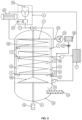
- the multiphase continuous vertical reactor has (see figure 1 ): a biomass and bio solids supply system (1), an evaporation chamber (2) with a vacuum multiple effect fast evaporation system by means of an adiabatic expansion valve (3), a pyrolysis chamber (5), a gasification and combustion chamber (6), a condensation and catalysis system (7).
- the reactor has a roasting chamber (4), located between the evaporation chamber (2) and the pyrolysis chamber (5), which allows additional treatment of the biomass that requires it.
- the process for obtaining bio hydrocarbons and energy from substrates with high moisture content of the present invention is characterized by being continuous and autothermal.
- the material flows continuously from one chamber to another to achieve a progressive transformation by gradually raising its temperature and separating the liquid, gaseous and liquid phases.
- roasting and pyrolysis of the dehydrated material is done, by heating up to 550 °C, preferably in vacuum condition, from 20% to 80%, to reduce this temperature by 20% and release volatile matter.
- This process ideal for microalgae biomass, can be used for any other type of wet biomass, defined as that which can be more than 50% HBH, up to 95% HBH.
- preferred biomasses to perform this process are: microalga biomass, residual biomasses or their mixtures present in sludge and/or solids in liquid substrates of urban, rural and industrial origin, and other denser bio solids.
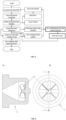
- the multiphase continuous vertical reactor which functions as a down flow reactor, is composed of a vertical vessel (10), a vertical shaft (8), multiple chambers: evaporation (2), pyrolysis (5), gasification and combustion (6). Each chamber is a thermolysis phase. These chambers are connected to each other by hermetically sealed, airlock-type gates (9) to operate under vacuum ( Figures 2 and 3 ).
- the reactor has a roasting chamber (4), located between the evaporation chamber (2) and the pyrolysis chamber (5), which allows additional treatment for the biomass that requires it, due to particle agglomeration conditions and/or tendency to compact with strong temperature changes.
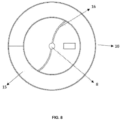
- the vertical vessel (10), with a cylindrical or square section supporting structure, has a vertical rotating shaft (8) driven by a drive system (22), preferably of the geared motor type: electric motor, speed reduction gearbox, shaft coupling and shaft supported by bearings, to which spiral arms (16) are attached.
- a drive system 22
- geared motor type electric motor, speed reduction gearbox, shaft coupling and shaft supported by bearings, to which spiral arms (16) are attached.
- All the chambers that are part of the reactor have a self-powered inner jacket of hot gases, located on the walls of the chambers (2,4,5,6), which perform indirect heating by conduction and radiant surfaces ( Figure 6 ).
- the vertical chambers have helical agitators or spiral arms (16) to facilitate the movement of the material inside and between them ( Figure 8 ).
- the separation between chambers is made with hermetically sealed sluice gates (9), with movement by hydraulic and/or pneumatic drive.
- the material moves between chambers through these gates, without losing the airtightness ( Figure 6 ).
- the supply system (1) consists of a pre-mixer (24), a positive displacement pump for biomass and sludge (25), a shell and tube heat exchanger (23).
- the evaporation chamber (2) connected to the supply system (1), has one or several nozzles or adiabatic expansion valve at its inlet (3), which generate an instantaneous evaporation effect and has a self-cleaning rotor (11) that prevents clogging and performs instantaneous evaporation in consecutive phases under vacuum, as shown in figure 5 .
- the vapor separated in the evaporation chamber (2), extracted by a vacuum pump, is recovered to be re-fed to the gasification and combustion chamber (6), by means of the connecting duct (20), through the steam injectors (21).
- This evaporation chamber (2) allows the expansion of the wet biomass for vapor, liquid and solid phase separation with innovative recirculation method to generate two or more instantaneous multi-instantaneous evaporation effects, reducing in each step, not less than 15% of HBH of the substrate.
- a vacuum pump (12) is connected to remove the cold vapor at low temperature for transfer to a heat recovery unit (23) that preheats the wet biomass at the inlet of the premixing system (24) before the sludge pump (25).
- the roasting chamber (4) when present, consists of a hermetic sealing gate (9), as shown in Figure 6 .
- the roasting chamber (4) is connected to the evaporation chamber (2) by means of the hermetic sealing gate (9), on the upper part; and similarly, it is connected by the bottom part with the pyrolysis chamber (5).
- the pyrolysis chamber (5) formed by a hermetic sealing gate (9), as shown in figure 6 .
- a pyrolysis gas outlet duct connected to the condensation and catalysis system (7).
- the evaporation (2), roasting (4) and pyrolysis (5) chambers have grinding bodies, such as spheres, rods or equivalent, to reduce the particle size of the material being processed.
- the roasting and pyrolysis chambers can be merged into one.
- the gasification and combustion chamber (6) has a chamber covered in refractory material (17), thermally insulated, with burners for oil and gas, and a rotating grate attached to the central movement axis (28).
- This gasification and combustion chamber (6) is lined with refractory and insulating material to withstand temperatures above 1200 °C.
- a condensation and catalysis system (7) comprising a bank of heat exchangers or flow-through condensers (19), as shown in Figure 9 , water jacketed and saturated with ferritic-based catalyst reagent that facilitates hydrocarbon precipitation.
- the heat retriever preheats the wet biomass before entering the pre-mixer (24).
- All operating variables are controlled by a central electronic system that synchronizes operations and operational parameters once the reactor operating curves are calibrated for different types of biomasses.
- the system is connected to an loT (Internet of Things) platform for remote monitoring and operation.
- the process applies to any type of wet biomass, preferably microalgae biomass, waste biomass or their mixtures present in sludge and/or solids in liquid substrates of urban, rural and industrial origin, more preferably with moisture content from 50% HBH to 95% HBH.
- the wet starting biomass is conditioned to contain volatile matter up to 60% and fixed carbon greater than 5%, calorific value greater than 5 MJ/kg and particle size of the solid fraction up to 25 mm, although it is not limited to these conditions because it is possible to make a pre-treatment to adjust the material to these conditions.
- the residual biomass with moisture up to 95% HBH enters the supply pump (25), which carries the material at a pressure between 7 MPa to 15 MPa and a temperature of 50 °C to 200 °C, depending on the characteristics of the material.
- An advantage of the present process is that it is not necessary to interrupt it for new wet biomass to enter the process, taking into account that the reactor is multiphase and of continuous operation. Therefore, once the substrate passes to the second and subsequent chambers, the first chamber can be loaded to start the transformation of more wet biomass that does not require prior drying.
- the material passes through a set of nozzles or adiabatic expansion valves (3), which reduces the pressure of the material at the outlet of the supply pump (25), below atmospheric pressure, between 80% to 20% vacuum producing a flash evaporation effect, which separates the water vapor from the solid fraction in the evaporation chamber (2); the material loses between 10% to 30% of the moisture in each pass through the evaporation chamber (2), thus requiring feedback cycles in the evaporation chamber (2), generating a multi flash evaporation effect.
- the vacuum in the evaporation chamber (2) is generated by the vacuum pump (12).
- the vapor separated in the evaporation chamber (2) is recovered and fed to the gasification and combustion chamber (6) by means of the connecting duct (20), through the steam injectors (21).
- This fed back vapor generates two effects, one of expansion of the bio char by activating it and the other one of increase of the calorific value of the synthesis gas by producing a higher proportion of hydrogen and methane.
- the vapor flow is regulated by a three-way metering valve (27).
- the material Once the material reaches a humidity of less than 30% HBH, it passes into the roasting (4) and pyrolysis (5) chambers through the hermetically sealed sluice gate (9), which connects the two chambers. The same happens for the passage of the material between the pyrolysis (5) and gasification/combustion chambers (6), through the airlock gate (9).
- the material being processed is heated in each chamber and is forced to move axially up-down and radially from center to periphery by the spiral arms (16), also known as helical agitators, which are fixed to the vertical axis of rotation (8), driven by a drive system (22), driven by a motor reducer system.
- spiral arms (16) also known as helical agitators, which are fixed to the vertical axis of rotation (8), driven by a drive system (22), driven by a motor reducer system.
- the bio char generated in the pyrolysis stage in the chamber (5) passes into the gasification / combustion chamber (6) through the hermetically sealed sluice gate valve (9).
- the bio char falls on the rotating conical grate (28), where a fraction not exceeding 30% of the processed volume is gasified and combusts on contact with the primary air supplied by the fan, to generate the heat necessary for the endothermic reactions of the evaporation, roasting, pyrolysis and gasification processes.
- Heat transfer takes place between the combustion gases and each chamber by means of an inner jacket of hot gases (15), insulated to the outside and radiating to the inside where the heat flows through the walls and floors to the material being processed.
- the waste heat from the combustion gases at the outlet of the reactor jacket is recovered in the heat exchanger (23) to preheat the sludge entering the supply system (1), in the pre-mixer (24).
- bio-oil and synthesis gas for the combustion process.
- an external burner connected to the heating jacket (15) of the reactor, is placed in addition to the rotating grate.
- the flow of hot gases in the heating jacket is controlled by butterfly flow valves and the retention time of the gases is optimized by using flow deflector dampers or baffles inside the heating jacket, as shown in figure 7 .
- the bio char and ash generated in the gasification and combustion chamber (6) are removed from the reactor by means of the auger (13).
- Example 1 Process for obtaining electrical and thermal energy from microalgae biomass.
- the supplying of the sludge or wet microalga biomass which can be more than 50% HBH, up to 95% HBH, is carried out at high pressure, from 7 to 15 MPa, bringing it from room temperature to a process temperature between 50 to 200 °C.
- This microalga slurry passes through an adiabatic expansion nozzle into an evaporation chamber that has a pressure between 20 to 80% vacuum with respect to atmospheric pressure.
- the expansion effect reduces the temperature to less than 80 °C, generating an instantaneous evaporation.
- the microalga sludge is recirculated several times until the humidity is reduced to less than 30%.
- the vapor is separated from the microalga biomass which passes to the pyrolysis process in another hermetic chamber with indirect heating where it acquires a temperature above 450 °C which allows it to release the volatile matter that passes to the bank of condensers and catalysts where it precipitates at a temperature below 60 °C obtaining the bio-oil, which is a hydrocarbon of medium and high molecular weight.
- the non-condensed gas below 60 °C is a synthesis gas composed of hydrocarbons of low molecular weight and high calorific value, above 30 MJ/kg.
- the material that does not volatilize in the pyrolysis chamber is composed of ashes and bio char, which passes to the gasification and combustion chamber to generate the heat required in the endothermic processes of transformation of the microalga biomass.
- This chamber can also operate with a fraction of the bio oil and synthesis gas, depending on the matter and energy balance.
- Bio oil can be used in thermal plants for electricity and/or heat generation in isolation and in combination, as in the case of Otto cycle internal combustion engines, Rankine cycle turbines (vapor and ORC organic fluid) and Bryton cycle and Stirling cycle external combustion engines, among others.
- Process dimensioning Balance of matter and energy. It consists in calculating, from the matter and energy balance, the input and output conditions for each of the drying and roasting processes, pyrolysis and gasification,for a capacity of 1.5 TDP. Table 1 presents the summary of the matter and energy balances by process and plant size.
- the first column identifies the row of data
- the second column identifies the heat treatment process and the product obtained from said process
- the third column states the thermodynamic variable being calculated
- the fourth column the unit of measurement in international system of units
- the fifth column classifies the three plant sizes for the expected capacities and the last column records explanatory notes or the source of information of the recorded data.
- Table 1 Matter and energy balance for plant sizes.
- Temperature °C 60 Design data from pilot plant. Enthalpy kJ/kg 13,800. 00 Experimental data 9 Gasifica tion / ashes Mass flow kg/h 1.21 Experimental data Pressure Pa 75,800. 00 Discharge at P atm. Temperature °C 834.4 Experimental data from pilot plant. Enthalpy kJ/kg - Non-combustible material
- the heat balance indicates that only the bio-oil drying process is autothermal, with 82% of the energy available in the material.
- the use of other products, such as dry microalga substrate, bio char and syngas, would require external fuel additions, in proportion to the deficit value indicated in parentheses, for each plant size.
- Process specifications Based on the pilot plant results, the microalga substrate thermal treatment processes are within the specification ranges indicated in Table 4 below. The source refers to the database where the specification value was obtained, presented as an annex to this report. Table 4. Process specifications. ID PROCESS VARIABLE UNITD MIN MAX 1 Power supply Mass flow Kg/h 30 90 Humidity % - 95 Temperature °C 10 34 Pressure kPa 70.0 110.0 2 Drying system Mass flow Kg/h 30 90 Humidity % 95 Temperature °C 10 34 Pressure kPa 70.0 110.0 3 Roasting system Mass flow Kg/h 3 10 Humidity % 5 20 Temperature °C 300 350 Pressure kPa 70.0 110.0 4 Pyrolysis system Mass flow Kg/h 5 20 Humidity % 5 20 Temperature °C 400 500 Pressure kPa 70.0 110.0 5 Gasification system Mass flow Kg/h 3 10 Humidity % 20 Temperature °C 900 1100 Pressure kPa 70.0 110.0
- the conversion efficiency of the cogeneration plant is 870 W/kg bio sludge at 30% humidity.
- Example 2 Process for obtaining hydrocarbons from bio solids in a municipal wastewater treatment plant (WWTP).
- Bio solids are a product originated after a stabilization process of organic sludge from wastewater treatment (WWTP). Stabilization is carried out to reduce its pathogenicity level, its fermentation power and its capacity to attract vectors-borne diseases. Stabilized sludge or bio solids are considered assimilable urban waste and, although they cannot be classified as toxic or hazardous, they do contain contaminants that require treatment.
- the process begins with the preparation of the bio solids: the material passes into the reactor to undergo the first stage of thermal transformation, which consists of raising the temperature to 120°C to remove excess moisture and leave the material ready for the next stage of thermolysis.
- the reactor is brought to a temperature of 300°C where the material confined inside, in a sealed chamber and in the absence of oxygen, releases volatile matter, oils and tars; at this temperature the material reaches a state of reduction, densifying and meeting the thermolysis parameters.
- the biomass is brought to temperatures above 500°C also in the absence of oxygen, where all the volatile matter has been converted into vapors and gases containing oils and tars that are discharged through a valve to achieve pyrolysis conditions.
- thermolysis and pyrolysis phases can be condensed, cooling them to temperatures below 80°C by means of a heat exchanger, thus condensing the vapors and obtaining the biofuel in liquid phase.
- the product that remains in the reactor in the pyrolysis phase is bio char and bio oils used as agricultural inputs.
Landscapes
- Chemical & Material Sciences (AREA)
- Engineering & Computer Science (AREA)
- Oil, Petroleum & Natural Gas (AREA)
- Organic Chemistry (AREA)
- Mechanical Engineering (AREA)
- Life Sciences & Earth Sciences (AREA)
- Combustion & Propulsion (AREA)
- Chemical Kinetics & Catalysis (AREA)
- General Engineering & Computer Science (AREA)
- General Chemical & Material Sciences (AREA)
- Materials Engineering (AREA)
- Wood Science & Technology (AREA)
- Health & Medical Sciences (AREA)
- Molecular Biology (AREA)
- Water Supply & Treatment (AREA)
- Hydrology & Water Resources (AREA)
- Environmental & Geological Engineering (AREA)
- Thermal Sciences (AREA)
- Physics & Mathematics (AREA)
- Sustainable Development (AREA)
- Treatment Of Sludge (AREA)
- Production Of Liquid Hydrocarbon Mixture For Refining Petroleum (AREA)
- Processing Of Solid Wastes (AREA)
- Coke Industry (AREA)
- Solid-Fuel Combustion (AREA)
- Hydrogen, Water And Hydrids (AREA)
Applications Claiming Priority (2)
| Application Number | Priority Date | Filing Date | Title |
|---|---|---|---|
| CONC2020/0004451A CO2020004451A1 (es) | 2020-04-14 | 2020-04-14 | Reactor vertical continuo multifásico para la producción limpia de hidrocarburos y energía y proceso termoquímico realizado |
| PCT/IB2021/053082 WO2021209926A1 (es) | 2020-04-14 | 2021-04-14 | Reactor vertical continuo multifásico para la producción limpia de hidrocarburos y energía y proceso termoquímico realizado |
Publications (2)
| Publication Number | Publication Date |
|---|---|
| EP4137746A1 true EP4137746A1 (de) | 2023-02-22 |
| EP4137746A4 EP4137746A4 (de) | 2023-10-18 |
Family
ID=70613522
Family Applications (1)
| Application Number | Title | Priority Date | Filing Date |
|---|---|---|---|
| EP21787761.2A Withdrawn EP4137746A4 (de) | 2020-04-14 | 2021-04-14 | Vertikaler kontinuierlicher mehrphasenreaktor zur sauberen herstellung von kohlenwasserstoffen und energie sowie thermochemisches verfahren |
Country Status (12)
| Country | Link |
|---|---|
| US (1) | US20230159832A1 (de) |
| EP (1) | EP4137746A4 (de) |
| JP (1) | JP2024503769A (de) |
| CN (1) | CN115398151A (de) |
| AU (1) | AU2021254879A1 (de) |
| BR (1) | BR112022020813A2 (de) |
| CA (1) | CA3180337A1 (de) |
| CL (1) | CL2022002823A1 (de) |
| CO (1) | CO2020004451A1 (de) |
| DO (1) | DOP2022000219A (de) |
| MX (1) | MX2022012875A (de) |
| WO (1) | WO2021209926A1 (de) |
Families Citing this family (1)
| Publication number | Priority date | Publication date | Assignee | Title |
|---|---|---|---|---|
| DE102022123547A1 (de) * | 2022-09-14 | 2024-03-14 | Fraunhofer-Gesellschaft zur Förderung der angewandten Forschung eingetragener Verein | Einstufiges Verfahren und Vorrichtung zur Herstellung von reformiertem Pyrolyseöl und wasserstoffreichem Pyrolysegas |
Family Cites Families (27)
| Publication number | Priority date | Publication date | Assignee | Title |
|---|---|---|---|---|
| IT1032926B (it) * | 1975-05-19 | 1979-06-20 | Pagnozzi Ernesto Guglielmo | Procedimento a vuoto per essiccare legname massiccio particolarmente per essiccare legname delicato e o facilmente collassabile |
| US4100032A (en) | 1977-07-25 | 1978-07-11 | Husky Industries Inc. | Process for carbonizing lignite coal |
| US4215637A (en) | 1979-04-02 | 1980-08-05 | Envirotech Corporation | System for combustion of wet waste materials |
| US4308807A (en) | 1980-03-17 | 1982-01-05 | Stokes Samuel L | Apparatus for pyrolysis of municipal waste utilizing heat recovery |
| DE3049250C2 (de) * | 1980-12-27 | 1985-10-24 | Kernforschungsanlage Jülich GmbH, 5170 Jülich | Einrichtung mit Schweldrehtrommel und Schachtofen |
| US4732092A (en) | 1985-09-30 | 1988-03-22 | G.G.C., Inc. | Pyrolysis and combustion apparatus |
| RU2152561C1 (ru) * | 1998-01-22 | 2000-07-10 | Институт проблем химической физики РАН | Способ переработки конденсированных горючих |
| US7452392B2 (en) | 2003-11-29 | 2008-11-18 | Nick Peter A | Process for pyrolytic heat recovery enhanced with gasification of organic material |
| US8707875B2 (en) * | 2009-05-18 | 2014-04-29 | Covanta Energy Corporation | Gasification combustion system |
| EP2189512A1 (de) * | 2008-11-24 | 2010-05-26 | Sa Cockerill Maintenance Et Ingenierie | Röstverfahren der Biomasse und Kontrolle dieses Verfahrens |
| US8776700B2 (en) * | 2009-03-26 | 2014-07-15 | Elio Faussone | System and process for the pyrolysation and gasification of organic substances |
| US8276289B2 (en) * | 2009-03-27 | 2012-10-02 | Terra Green Energy, Llc | System and method for preparation of solid biomass by torrefaction |
| EP2236588B1 (de) * | 2009-04-02 | 2012-07-04 | General Electric Company | Verfahren zur Verwendung von Pyrolysewasser |
| WO2011071676A1 (en) | 2009-12-11 | 2011-06-16 | Wyssmont Company Inc. | Apparatus and method for continuous lyophilization |
| US20110197797A1 (en) | 2010-02-18 | 2011-08-18 | Chavond-Barry Engineering Corp. | Method and apparatus for efficient production of activated carbon |
| DE102010036425A1 (de) | 2010-07-15 | 2012-01-19 | Polysius Ag | Vorrichtung und Verfahren zur Trocknung und Torrefizierung von wenigstens einem kohlenstoffhaltigen Stoffstrom in einem Etagenofen |
| US20130199920A1 (en) * | 2011-02-14 | 2013-08-08 | Elhan Demir | Device and method for the thermochemical harmonising and gasification of wet biomass |
| CN102168907B (zh) * | 2011-03-31 | 2012-10-24 | 东莞市可迪红木坊家居用品有限公司 | 一种多功能木材真空自动烘干装备及其工作方式 |
| WO2013036694A1 (en) * | 2011-09-06 | 2013-03-14 | Johnston John C | A thermal conversion combined torrefaction and pyrolysis reactor system and method thereof |
| FR2982273B1 (fr) * | 2011-11-09 | 2014-03-14 | Commissariat Energie Atomique | Reacteur de sechage et de torrefaction de biomasse, de preference ligno-cellulosique |
| US9327208B2 (en) * | 2012-04-30 | 2016-05-03 | Kior, Llc | Bio-oil fractionation |
| CN204438139U (zh) | 2014-12-11 | 2015-07-01 | 北京瑞克森地环保技术有限公司 | 多膛炉污泥焚烧设备 |
| CN105859097A (zh) | 2016-05-24 | 2016-08-17 | 华南理工大学 | 一种结合热电厂余热利用污泥干燥方法及其装置 |
| CN206375861U (zh) * | 2016-11-28 | 2017-08-04 | 鑫宏润(天津)农业生物技术服务有限公司 | 一种生物质裂解气化炉转换装置 |
| CN107987890A (zh) * | 2017-12-28 | 2018-05-04 | 北京神雾电力科技有限公司 | 有机污泥热解气化系统和热解气化方法 |
| CN207958275U (zh) * | 2018-01-24 | 2018-10-12 | 江苏大学 | 一种碳基燃料化学链燃烧气化耦合装置 |
| RU2703617C1 (ru) | 2018-12-28 | 2019-10-21 | Общество с ограниченной ответственностью "Современные пиролизные технологии" (ООО "СПТ") | Реактор для переработки твердого топлива с получением горючего газа |
-
2020
- 2020-04-14 CO CONC2020/0004451A patent/CO2020004451A1/es unknown
-
2021
- 2021-04-14 CN CN202180028849.8A patent/CN115398151A/zh active Pending
- 2021-04-14 CA CA3180337A patent/CA3180337A1/en active Pending
- 2021-04-14 AU AU2021254879A patent/AU2021254879A1/en not_active Withdrawn
- 2021-04-14 EP EP21787761.2A patent/EP4137746A4/de not_active Withdrawn
- 2021-04-14 BR BR112022020813A patent/BR112022020813A2/pt not_active Application Discontinuation
- 2021-04-14 MX MX2022012875A patent/MX2022012875A/es unknown
- 2021-04-14 US US17/918,323 patent/US20230159832A1/en active Pending
- 2021-04-14 JP JP2022562963A patent/JP2024503769A/ja active Pending
- 2021-04-14 WO PCT/IB2021/053082 patent/WO2021209926A1/es not_active Ceased
-
2022
- 2022-10-13 DO DO2022000219A patent/DOP2022000219A/es unknown
- 2022-10-13 CL CL2022002823A patent/CL2022002823A1/es unknown
Also Published As
| Publication number | Publication date |
|---|---|
| AU2021254879A1 (en) | 2022-12-15 |
| US20230159832A1 (en) | 2023-05-25 |
| BR112022020813A2 (pt) | 2023-04-11 |
| DOP2022000219A (es) | 2023-09-29 |
| MX2022012875A (es) | 2022-11-08 |
| CN115398151A (zh) | 2022-11-25 |
| CA3180337A1 (en) | 2021-10-21 |
| CO2020004451A1 (es) | 2020-05-15 |
| WO2021209926A1 (es) | 2021-10-21 |
| JP2024503769A (ja) | 2024-01-29 |
| EP4137746A4 (de) | 2023-10-18 |
| CL2022002823A1 (es) | 2023-04-21 |
Similar Documents
| Publication | Publication Date | Title |
|---|---|---|
| Bridgwater et al. | A review of biomass pyrolysis and pyrolysis technologies | |
| US6039774A (en) | Pyrolytic conversion of organic feedstock and waste | |
| WO2016203232A1 (en) | A gasification system | |
| CN201530810U (zh) | 用于内热式连续制备生物质热解气化煤气的方法中的回转炉 | |
| RU2544669C1 (ru) | Способ переработки горючих углерод- и/или углеводородсодержащих продуктов и реактор для его осуществления | |
| RU2649446C1 (ru) | Способ и устройство переработки углеродсодержащих отходов | |
| JP2022551536A (ja) | Co2排出のない廃棄物-エネルギー変換 | |
| CN101850967B (zh) | 一种有机废物制取活性炭一体化装置及方法 | |
| EP4137746A1 (de) | Vertikaler kontinuierlicher mehrphasenreaktor zur sauberen herstellung von kohlenwasserstoffen und energie sowie thermochemisches verfahren | |
| AU2013316430A1 (en) | Power generation system | |
| WO2009025569A1 (fr) | Dispositif et procédé de production de gaz de synthèse et de semi-coke à partir de biomasse organique | |
| CN218665673U (zh) | 超导高效无害化污泥处理装置 | |
| JP6590359B1 (ja) | バイオマスを原料とする水素製造方法 | |
| JP5748333B2 (ja) | 電気加熱式バイオマスガス化装置 | |
| CN101921625B (zh) | 双筒燃烧气化制合成气的方法与装置 | |
| CN102099439B (zh) | 煤加工方法及其用于进行该方法的设备 | |
| RU2408820C1 (ru) | Установка для мультифазового пиролиза органического сырья | |
| Mufandi et al. | The comparison of bio-oil production from sugarcane trash, napier grass, and rubber tree in the circulating fluidized bed reactor | |
| US11142714B2 (en) | Highly efficient and compact syngas generation system | |
| JP7101159B2 (ja) | 廃棄物処理システム | |
| SU1120009A1 (ru) | Способ термической переработки пылевидного твердого топлива | |
| US1159675A (en) | Method of manufacturing gas. | |
| RU136800U1 (ru) | Газификатор твердого топлива | |
| RU2825949C1 (ru) | Способ газификации твердых топлив и газогенератор непрерывного действия для его осуществления | |
| CN104152182A (zh) | 一种生物质气化发电的方法 |
Legal Events
| Date | Code | Title | Description |
|---|---|---|---|
| STAA | Information on the status of an ep patent application or granted ep patent |
Free format text: STATUS: THE INTERNATIONAL PUBLICATION HAS BEEN MADE |
|
| PUAI | Public reference made under article 153(3) epc to a published international application that has entered the european phase |
Free format text: ORIGINAL CODE: 0009012 |
|
| STAA | Information on the status of an ep patent application or granted ep patent |
Free format text: STATUS: REQUEST FOR EXAMINATION WAS MADE |
|
| 17P | Request for examination filed |
Effective date: 20221111 |
|
| AK | Designated contracting states |
Kind code of ref document: A1 Designated state(s): AL AT BE BG CH CY CZ DE DK EE ES FI FR GB GR HR HU IE IS IT LI LT LU LV MC MK MT NL NO PL PT RO RS SE SI SK SM TR |
|
| RAP1 | Party data changed (applicant data changed or rights of an application transferred) |
Owner name: SSS TECHNOLOGIES CORP |
|
| DAV | Request for validation of the european patent (deleted) | ||
| DAX | Request for extension of the european patent (deleted) | ||
| A4 | Supplementary search report drawn up and despatched |
Effective date: 20230915 |
|
| RIC1 | Information provided on ipc code assigned before grant |
Ipc: C10B 57/10 20060101ALI20230911BHEP Ipc: C10B 53/02 20060101ALI20230911BHEP Ipc: C10B 47/32 20060101ALI20230911BHEP Ipc: F23G 7/10 20060101ALI20230911BHEP Ipc: F23G 5/027 20060101AFI20230911BHEP |
|
| GRAP | Despatch of communication of intention to grant a patent |
Free format text: ORIGINAL CODE: EPIDOSNIGR1 |
|
| STAA | Information on the status of an ep patent application or granted ep patent |
Free format text: STATUS: GRANT OF PATENT IS INTENDED |
|
| INTG | Intention to grant announced |
Effective date: 20250114 |
|
| STAA | Information on the status of an ep patent application or granted ep patent |
Free format text: STATUS: THE APPLICATION IS DEEMED TO BE WITHDRAWN |
|
| 18D | Application deemed to be withdrawn |
Effective date: 20250515 |