EP4137727B1 - Ventilaktuator - Google Patents
Ventilaktuator Download PDFInfo
- Publication number
- EP4137727B1 EP4137727B1 EP21218051.7A EP21218051A EP4137727B1 EP 4137727 B1 EP4137727 B1 EP 4137727B1 EP 21218051 A EP21218051 A EP 21218051A EP 4137727 B1 EP4137727 B1 EP 4137727B1
- Authority
- EP
- European Patent Office
- Prior art keywords
- gear
- magnet
- motor
- valve actuator
- disposed
- Prior art date
- Legal status (The legal status is an assumption and is not a legal conclusion. Google has not performed a legal analysis and makes no representation as to the accuracy of the status listed.)
- Active
Links
Images







Classifications
-
- F—MECHANICAL ENGINEERING; LIGHTING; HEATING; WEAPONS; BLASTING
- F16—ENGINEERING ELEMENTS AND UNITS; GENERAL MEASURES FOR PRODUCING AND MAINTAINING EFFECTIVE FUNCTIONING OF MACHINES OR INSTALLATIONS; THERMAL INSULATION IN GENERAL
- F16K—VALVES; TAPS; COCKS; ACTUATING-FLOATS; DEVICES FOR VENTING OR AERATING
- F16K27/00—Construction of housing; Use of materials therefor
- F16K27/02—Construction of housing; Use of materials therefor of lift valves
- F16K27/029—Electromagnetically actuated valves
-
- F—MECHANICAL ENGINEERING; LIGHTING; HEATING; WEAPONS; BLASTING
- F16—ENGINEERING ELEMENTS AND UNITS; GENERAL MEASURES FOR PRODUCING AND MAINTAINING EFFECTIVE FUNCTIONING OF MACHINES OR INSTALLATIONS; THERMAL INSULATION IN GENERAL
- F16H—GEARING
- F16H35/00—Gearings or mechanisms with other special functional features
- F16H35/10—Arrangements or devices for absorbing overload or preventing damage by overload
-
- F—MECHANICAL ENGINEERING; LIGHTING; HEATING; WEAPONS; BLASTING
- F16—ENGINEERING ELEMENTS AND UNITS; GENERAL MEASURES FOR PRODUCING AND MAINTAINING EFFECTIVE FUNCTIONING OF MACHINES OR INSTALLATIONS; THERMAL INSULATION IN GENERAL
- F16K—VALVES; TAPS; COCKS; ACTUATING-FLOATS; DEVICES FOR VENTING OR AERATING
- F16K5/00—Plug valves; Taps or cocks comprising only cut-off apparatus having at least one of the sealing faces shaped as a more or less complete surface of a solid of revolution, the opening and closing movement being predominantly rotary
- F16K5/06—Plug valves; Taps or cocks comprising only cut-off apparatus having at least one of the sealing faces shaped as a more or less complete surface of a solid of revolution, the opening and closing movement being predominantly rotary with plugs having spherical surfaces; Packings therefor
- F16K5/0647—Spindles or actuating means
-
- F—MECHANICAL ENGINEERING; LIGHTING; HEATING; WEAPONS; BLASTING
- F16—ENGINEERING ELEMENTS AND UNITS; GENERAL MEASURES FOR PRODUCING AND MAINTAINING EFFECTIVE FUNCTIONING OF MACHINES OR INSTALLATIONS; THERMAL INSULATION IN GENERAL
- F16K—VALVES; TAPS; COCKS; ACTUATING-FLOATS; DEVICES FOR VENTING OR AERATING
- F16K31/00—Actuating devices; Operating means; Releasing devices
- F16K31/02—Actuating devices; Operating means; Releasing devices electric; magnetic
- F16K31/04—Actuating devices; Operating means; Releasing devices electric; magnetic using a motor
-
- F—MECHANICAL ENGINEERING; LIGHTING; HEATING; WEAPONS; BLASTING
- F16—ENGINEERING ELEMENTS AND UNITS; GENERAL MEASURES FOR PRODUCING AND MAINTAINING EFFECTIVE FUNCTIONING OF MACHINES OR INSTALLATIONS; THERMAL INSULATION IN GENERAL
- F16K—VALVES; TAPS; COCKS; ACTUATING-FLOATS; DEVICES FOR VENTING OR AERATING
- F16K31/00—Actuating devices; Operating means; Releasing devices
- F16K31/02—Actuating devices; Operating means; Releasing devices electric; magnetic
- F16K31/04—Actuating devices; Operating means; Releasing devices electric; magnetic using a motor
- F16K31/047—Actuating devices; Operating means; Releasing devices electric; magnetic using a motor characterised by mechanical means between the motor and the valve, e.g. lost motion means reducing backlash, clutches, brakes or return means
-
- F—MECHANICAL ENGINEERING; LIGHTING; HEATING; WEAPONS; BLASTING
- F16—ENGINEERING ELEMENTS AND UNITS; GENERAL MEASURES FOR PRODUCING AND MAINTAINING EFFECTIVE FUNCTIONING OF MACHINES OR INSTALLATIONS; THERMAL INSULATION IN GENERAL
- F16K—VALVES; TAPS; COCKS; ACTUATING-FLOATS; DEVICES FOR VENTING OR AERATING
- F16K31/00—Actuating devices; Operating means; Releasing devices
- F16K31/02—Actuating devices; Operating means; Releasing devices electric; magnetic
- F16K31/06—Actuating devices; Operating means; Releasing devices electric; magnetic using a magnet, e.g. diaphragm valves, cutting off by means of a liquid
-
- F—MECHANICAL ENGINEERING; LIGHTING; HEATING; WEAPONS; BLASTING
- F16—ENGINEERING ELEMENTS AND UNITS; GENERAL MEASURES FOR PRODUCING AND MAINTAINING EFFECTIVE FUNCTIONING OF MACHINES OR INSTALLATIONS; THERMAL INSULATION IN GENERAL
- F16K—VALVES; TAPS; COCKS; ACTUATING-FLOATS; DEVICES FOR VENTING OR AERATING
- F16K31/00—Actuating devices; Operating means; Releasing devices
- F16K31/02—Actuating devices; Operating means; Releasing devices electric; magnetic
- F16K31/06—Actuating devices; Operating means; Releasing devices electric; magnetic using a magnet, e.g. diaphragm valves, cutting off by means of a liquid
- F16K31/08—Actuating devices; Operating means; Releasing devices electric; magnetic using a magnet, e.g. diaphragm valves, cutting off by means of a liquid using a permanent magnet
- F16K31/084—Actuating devices; Operating means; Releasing devices electric; magnetic using a magnet, e.g. diaphragm valves, cutting off by means of a liquid using a permanent magnet the magnet being used only as a holding element to maintain the valve in a specific position, e.g. check valves
-
- F—MECHANICAL ENGINEERING; LIGHTING; HEATING; WEAPONS; BLASTING
- F16—ENGINEERING ELEMENTS AND UNITS; GENERAL MEASURES FOR PRODUCING AND MAINTAINING EFFECTIVE FUNCTIONING OF MACHINES OR INSTALLATIONS; THERMAL INSULATION IN GENERAL
- F16K—VALVES; TAPS; COCKS; ACTUATING-FLOATS; DEVICES FOR VENTING OR AERATING
- F16K31/00—Actuating devices; Operating means; Releasing devices
- F16K31/44—Mechanical actuating means
- F16K31/52—Mechanical actuating means with crank, eccentric, or cam
- F16K31/524—Mechanical actuating means with crank, eccentric, or cam with a cam
- F16K31/52408—Mechanical actuating means with crank, eccentric, or cam with a cam comprising a lift valve
- F16K31/52425—Mechanical actuating means with crank, eccentric, or cam with a cam comprising a lift valve with a ball-shaped valve member
-
- F—MECHANICAL ENGINEERING; LIGHTING; HEATING; WEAPONS; BLASTING
- F16—ENGINEERING ELEMENTS AND UNITS; GENERAL MEASURES FOR PRODUCING AND MAINTAINING EFFECTIVE FUNCTIONING OF MACHINES OR INSTALLATIONS; THERMAL INSULATION IN GENERAL
- F16K—VALVES; TAPS; COCKS; ACTUATING-FLOATS; DEVICES FOR VENTING OR AERATING
- F16K31/00—Actuating devices; Operating means; Releasing devices
- F16K31/44—Mechanical actuating means
- F16K31/53—Mechanical actuating means with toothed gearing
-
- F—MECHANICAL ENGINEERING; LIGHTING; HEATING; WEAPONS; BLASTING
- F16—ENGINEERING ELEMENTS AND UNITS; GENERAL MEASURES FOR PRODUCING AND MAINTAINING EFFECTIVE FUNCTIONING OF MACHINES OR INSTALLATIONS; THERMAL INSULATION IN GENERAL
- F16K—VALVES; TAPS; COCKS; ACTUATING-FLOATS; DEVICES FOR VENTING OR AERATING
- F16K31/00—Actuating devices; Operating means; Releasing devices
- F16K31/44—Mechanical actuating means
- F16K31/53—Mechanical actuating means with toothed gearing
- F16K31/535—Mechanical actuating means with toothed gearing for rotating valves
-
- F—MECHANICAL ENGINEERING; LIGHTING; HEATING; WEAPONS; BLASTING
- F16—ENGINEERING ELEMENTS AND UNITS; GENERAL MEASURES FOR PRODUCING AND MAINTAINING EFFECTIVE FUNCTIONING OF MACHINES OR INSTALLATIONS; THERMAL INSULATION IN GENERAL
- F16K—VALVES; TAPS; COCKS; ACTUATING-FLOATS; DEVICES FOR VENTING OR AERATING
- F16K5/00—Plug valves; Taps or cocks comprising only cut-off apparatus having at least one of the sealing faces shaped as a more or less complete surface of a solid of revolution, the opening and closing movement being predominantly rotary
- F16K5/08—Details
- F16K5/22—Features relating to lubrication
- F16K5/227—Features relating to lubrication for plugs with spherical surfaces
-
- H—ELECTRICITY
- H02—GENERATION; CONVERSION OR DISTRIBUTION OF ELECTRIC POWER
- H02K—DYNAMO-ELECTRIC MACHINES
- H02K49/00—Dynamo-electric clutches; Dynamo-electric brakes
- H02K49/10—Dynamo-electric clutches; Dynamo-electric brakes of the permanent-magnet type
- H02K49/104—Magnetic couplings consisting of only two coaxial rotary elements, i.e. the driving element and the driven element
- H02K49/106—Magnetic couplings consisting of only two coaxial rotary elements, i.e. the driving element and the driven element with a radial air gap
-
- F—MECHANICAL ENGINEERING; LIGHTING; HEATING; WEAPONS; BLASTING
- F16—ENGINEERING ELEMENTS AND UNITS; GENERAL MEASURES FOR PRODUCING AND MAINTAINING EFFECTIVE FUNCTIONING OF MACHINES OR INSTALLATIONS; THERMAL INSULATION IN GENERAL
- F16H—GEARING
- F16H19/00—Gearings comprising essentially only toothed gears or friction members and not capable of conveying indefinitely-continuing rotary motion
- F16H19/001—Gearings comprising essentially only toothed gears or friction members and not capable of conveying indefinitely-continuing rotary motion for conveying reciprocating or limited rotary motion
-
- F—MECHANICAL ENGINEERING; LIGHTING; HEATING; WEAPONS; BLASTING
- F16—ENGINEERING ELEMENTS AND UNITS; GENERAL MEASURES FOR PRODUCING AND MAINTAINING EFFECTIVE FUNCTIONING OF MACHINES OR INSTALLATIONS; THERMAL INSULATION IN GENERAL
- F16H—GEARING
- F16H37/00—Combinations of mechanical gearings, not provided for in groups F16H1/00 - F16H35/00
- F16H37/02—Combinations of mechanical gearings, not provided for in groups F16H1/00 - F16H35/00 comprising essentially only toothed or friction gearings
- F16H37/04—Combinations of toothed gearings only
Definitions
- the disclosure relates to a valve actuator. More particularly, the disclosure relates to a valve actuator for opening and closing a ball valve.
- a ball valve is an opening/closing means that is widely used to supply or cut off the supply of a working fluid to a required place through a pipe coupled to two opposite sides of the main body of the valve by opening and closing the pipe by automatically rotating a ball thereinside by way of a motor.
- a conventional ball valve actuator connects the shaft of the gear motor with the output shaft of the ball valve through a cam and uses a sensor or step motor to turn the output shaft by an intended angle.
- a physical stopper is used to limit the rotation angle of the output shaft.
- Korean Patent No. 0392198 discloses controlling to stop the rotation of the motor, with the gear in contact with the stopper, through a limiter switch.
- Patent Document 1 Korean Patent No. 10-0392198B1 registered on July 22, 2003 .
- DE 11 2015 003071 T5 discloses a double offset valve in which a rotation shaft is eccentrically disposed from a center of a valve hole of a valve seat, and a sealing surface of the valve element is eccentrically disposed from the rotation shaft.
- US 2010/170763 A1 discloses a transmission device with overload protection.
- US 4 808 869 A discloses a motor with an integral magnetic torque limiting coupling.
- DE 11 2018 004762 T5 discloses a double eccentric valve including a valve element provided with a rotatable shaft eccentrically disposed from a center of a valve opening of a valve seat.
- KR 101 611 977 B1 discloses an actuator with an impact absorbing-type stopper.
- GB 2 340 209 A discloses a torque limited motor operated valve.
- An object of the disclosure is to provide a valve actuator capable of preventing damage to a gear when torque is applied from a motor with the gear in contact with a stopper.
- Another object of the disclosure is to provide a valve actuator capable of damping the torque of a motor applied due to over-output.
- Another object of the disclosure is to provide a valve actuator capable of reducing manufacturing costs.
- Another object is to provide a valve actuator capable of operating even under a high-speed slip condition, e.g., at thousands of rpm.
- Another object of the disclosure is to provide a valve actuator capable of lubricating a component to prevent damage to the component under a high-speed slip condition.
- a valve actuator comprises a housing, a motor disposed on the housing, a drive gear coupled to a motor shaft of the motor, a transfer gear engaging with the drive gear and rotating according to a predetermined gear ratio when the drive gear rotates, an output gear coupled to an output shaft and engaging with the transfer gear, and a stopper disposed in the housing and limiting a rotation of the output gear.
- the transfer gear comprises an outer part, an inner part disposed in the outer part, a first magnet disposed on the outer part, and a second magnet disposed on the inner part and facing the first magnet.
- the first magnet and the second magnet may have different polarities.
- An attractive force between the first magnet and the second magnet may be larger than an average output force of the motor and smaller than a maximum output force of the motor.
- the first magnet may comprise a plurality of first magnet units having different polarities between adjacent magnet units
- the second magnet may comprise a plurality of second magnet units having different polarities between adjacent magnet units and individually facing the plurality of first magnet units.
- the motor may be a DC motor.
- DC motors since it may be applied to DC motors that are inexpensive as compared with AC motors, it is possible to reduce the manufacturing costs of the product.
- An upper end and lower end of the inner part are supported by an inner surface of the housing.
- An upper or lower end of the outer part is vertically supported by the inner part.
- a height of the first magnet is larger than a height of the second magnet.
- a vertical center of the first magnet When the upper end of the outer part is vertically supported by the inner part, a vertical center of the first magnet may be disposed above a vertical center of the second magnet, and when the lower end of the outer part is vertically supported by the inner part, the vertical center of the first magnet may be disposed below the vertical center of the second magnet.
- the inner part may comprise a groove formed in a region supporting the upper end or lower end of the outer part.
- a lubricant may be disposed in the groove. The lubricant may perform lubrication to prevent damage to the components under the high-speed slip condition.
- the transfer gear may comprise a first gear engaging with the drive gear, a second gear engaging with the first gear, and a third gear engaging with the second gear.
- the first gear may comprise the outer part, the inner part, the first magnet, and the second magnet.
- a valve actuator may comprise a housing, a motor disposed on the housing, a drive gear coupled to a motor shaft of the motor, an output gear coupled to an output shaft and engaging with the drive gear, and a stopper disposed in the housing and limiting a rotation radius of the output gear.
- the drive gear may comprise an outer part, an inner part disposed in the outer part, a first magnet disposed on the outer part, and a second magnet disposed on the inner part and facing the first magnet.
- gear shaft idles due to the first magnet and the second magnet during over-output of the motor, it is possible to damp the torque of the motor applied due to over-output and hence prevent damage to the drive gear and output gear.
- the inner part may be coupled to a motor shaft and rotate along with the motor shaft.
- An upper or lower end of the outer part is vertically supported by the inner part.
- a height of the first magnet may be larger than a height of the second magnet.
- a vertical center of the first magnet When the upper end of the outer part is vertically supported by the inner part, a vertical center of the first magnet may be disposed above a vertical center of the second magnet, and when the lower end of the outer part is vertically supported by the inner part, the vertical center of the first magnet may be disposed below the vertical center of the second magnet.
- the inner part may comprise a groove formed in an area supporting the upper end or lower end of the outer part.
- a lubricant may be disposed in the groove. The lubricant may perform lubrication to prevent damage to the components under the high-speed slip condition.
- a valve actuator may comprise a housing, a motor disposed on the housing, a drive gear coupled to a motor shaft of the motor, a transfer gear engaging with the drive gear and rotating according to a first gear ratio when the drive gear rotates, an output gear coupled to an output shaft and engaging with the transfer gear, and a stopper disposed in the housing and limiting a rotation radius of the output gear.
- the transfer gear may comprise a first transfer gear, a second transfer gear rotating according to a second gear ratio when the first transfer gear rotates, a cylindrical first magnet disposed on the first transfer gear, and a cylindrical second magnet disposed on the second transfer gear.
- the first magnet and the second magnet may horizontally overlap each other, with a predetermined gap formed therebetween.
- gear shaft idles due to the first magnet and the second magnet during over-output of the motor, it is possible to damp the torque of the motor applied due to over-output and hence prevent damage to the drive gear, transfer gear, and output gear.
- a valve actuator may comprise a housing, a motor disposed on the housing, a drive gear coupled to a motor shaft of the motor, a cylindrical first magnet coupled to the drive gear, an output gear coupled to an output shaft, a cylindrical second magnet coupled to the output gear, and a stopper disposed in the housing and limiting a rotation radius of the output gear.
- the first magnet and the second magnet horizontally overlap each other, with a predetermined gap formed therebetween.
- gear shaft idles due to the first magnet and the second magnet during over-output of the motor, it is possible to damp the torque of the motor applied due to over-output and hence prevent damage to the drive gear and output gear.
- the first magnet may comprise a plurality of first magnet units circumferentially arranged
- the second magnet may comprise a plurality of second magnet units circumferentially arranged.
- the plurality of first magnet units may be magnetized to have different poles from neighboring magnet units
- the plurality of second magnet units may be magnetized to have different poles from neighboring magnet units.
- the first magnet unit and the second magnet unit facing each other, among the plurality of first magnet units and the plurality of second magnet units, may have different polarities.
- the ratio of the number of the plurality of first magnet units to the number of the plurality of second magnet units may be identical to the second gear ratio.
- valve actuator capable of preventing damage to a gear when torque is applied from a motor with the gear in contact with a stopper.
- valve actuator capable of damping the torque of a motor applied due to over-output.
- valve actuator capable of reducing manufacturing costs.
- valve actuator capable of operating even under a high-speed slip condition, e.g., at thousands of rpm.
- valve actuator capable of lubricating a component to prevent damage to the component under a high-speed slip condition.
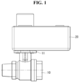
- FIG. 1 is a front view illustrating a ball valve and a valve actuator according to a first embodiment of the disclosure.
- FIG. 2 is a perspective view illustrating a valve actuator according to the first embodiment of the disclosure.
- FIG. 3 is an exploded perspective view illustrating a valve actuator according to the first embodiment of the disclosure.
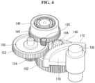
- FIGS. 4 and 5 are perspective views illustrating some components of a valve actuator according to the first embodiment of the disclosure.
- FIG. 6 is a perspective view illustrating a first gear according to the first embodiment of the disclosure.
- FIG. 7 is a plan view illustrating a first gear according to the first embodiment of the disclosure.
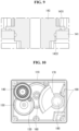
- FIG. 8 is a cross-sectional view illustrating a valve actuator according to the first embodiment of the disclosure.
- FIG. 9 is an enlarged view illustrating some components of FIG. 8 .
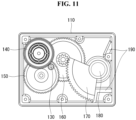
- FIGS. 10 , 11 , and 12 are views illustrating the operation of a valve actuator according to the first embodiment of the disclosure.
- FIG. 13 is an exploded perspective view illustrating
- a valve actuator 20 may include a housing 110, a motor 120, a drive gear 130, transfer gears 140, 150, and 160, an output gear 170, an output shaft 180, a stopper 190, and a magnet 200.
- the valve actuator 20 may omit some of the components or add more components.
- the valve actuator 20 may be coupled to an upper portion of a plate 11 coupled to an upper portion of a ball valve 10.
- the output shaft 180 of the actuator 20 may be coupled to a stem 13 of the ball valve 10. As the output shaft 180 of the actuator 20 rotates, the stem 13 may rotate, and a ball 16 of the ball valve 10 may rotate, opening or closing the ball valve 10.
- the ball valve 10 may include a stem fixing part 15 for coupling the stem 13 and an O-ring 14 disposed under the stem 13.
- the housing 110 may be formed in a hexahedral shape.
- the housing 110 may form the exterior of the valve actuator 20.
- the housing 110 may be disposed on one side of the ball valve 10.
- the housing 110 may be disposed on the ball valve 10.
- the motor 120, the drive gear 130, the transfer gears 140, 150, and 160, the output gear 170, the output shaft 180, and the stopper 190 may be disposed.
- the motor 120 may be disposed on the housing 110.
- the motor 120 may be coupled to a recess of the housing 110 so that one side thereof may be disposed in the housing 110, and the other side may protrude to the outside of the housing 110. This may enhance space efficiency.
- the drive gear 130 may be coupled to a motor shaft of the motor 120.
- the motor 120 may a direct current (DC) motor.
- the motor 120 may be an alternating current (AC) motor.
- AC alternating current
- the manufacturing costs of the valve actuator 20 may be reduced as compared with when the motor 120 is an AC motor.
- a DC motor may present poor rpm control accuracy as compared with an AC motor, and this may be supplemented by the physical stopper 190 of the valve actuator.
- the drive gear 130 may be coupled to the motor shaft of the motor 120. When the motor shaft of the motor 120 rotates in a first direction, the drive gear 130 may rotate in the first direction and, when the motor shaft rotates in a second direction, the drive gear 130 may rotate in the second direction.
- the drive gear 130 may engage with the transfer gears 140, 150, and 160.
- the drive gear 130 may be an external gear.
- the transfer gears 140, 150, and 160 may engage with the drive gear 130.
- the transfer gears 140, 150, and 160 may rotate according to a predetermined gear ratio when the drive gear 130 rotates.
- the transfer gears 140, 150, and 160 may engage with the output gear 170.
- the transfer gears 140, 150, and 160 may reduce the speed of the drive gear 130 at a predetermined gear ratio and transfer it to the output gear 170.
- the transfer gears 140, 150, and 160 may increase the torque transferred from the drive gear 130 and transfer it to the output gear 170.
- the transfer gears 140, 150, and 160 may include a first gear 140, a second gear 150, and a third gear 160.
- the first gear 140 may engage with the drive gear 130.
- the first gear 140 may engage with the second gear 150.
- the first gear 140 may engage with the drive gear 130 and may rotate at a predetermined gear ratio with respect to the drive gear 130.
- the first gear 140 may engage with the second gear 150 to rotate the second gear 150 at a predetermined gear ratio with respect to the first gear 140.
- the first gear 140 may include an outer part 141, a first external gear 142, an inner part 143, a second external gear 144, and magnets 200.
- the outer part 141 may be disposed outside the inner part 143.
- the outer part 141 may be radially spaced apart from the inner part 143.
- the first external gear 142 may be formed on the outer part 141.
- the first magnet 210 may be disposed on the outer part 141.
- the first external gear 142 may engage with the drive gear 130.
- the outer part 141 of the first gear 140 may rotate at a predetermined gear ratio with respect to the drive gear 130.
- the magnets 200 may include a first magnet 210 disposed on the outer part 141 and a second magnet 220 disposed on the inner part 143.
- the first magnet 210 may be radially spaced apart from the second magnet 220.
- a predetermined gap g1 may be formed between the inner surface of the first magnet 210 and the outer surface of the second magnet 220.
- the second magnet 220 may be disposed in the first magnet 210.
- the first magnet 210 and the second magnet 220 may have different polarities.
- the respective areas of the first magnet 210 and the second magnet 220, which face each other, may have different polarities. For example, if a first area of the first magnet 210 has an N pole, a first area of the second magnet 220 facing the first area of the first magnet 210 may have an S pole.
- the first magnet 210 may rotate according to the rotation of the outer part 141, and the second magnet 220 may rotate along with the first magnet 210 by magnetic force.
- the outer part 141 idles with respect to the inner part 143 due to the first magnet 210 and the second magnet 220, preventing damage to the drive gear 130, the transfer gears 140, 150, and 160, and the output gear 170.
- the attractive force between the first magnet 210 and the second magnet 220 may be larger than the average output of the motor 120 and smaller than the maximum output of the motor 120.
- the outer part 141 idles with respect to the inner part 143 due to the first magnet 210 and the second magnet 220, damping the torque of the motor 120 applied due to the over-output and hence preventing damage to the drive gear 130, the transfer gears 140, 150, and 160, and the output gear 170. In particular, this may compensate for the over-output of the motor 120 that may occur if the motor 120 is formed of a low-cost DC motor.
- the first magnet 210 may include a plurality of first magnet units 212, 214, 216, and 218 having polarities different from those of adjacent magnet units.
- the second magnet 220 may include a plurality of second magnet units 222, 224, 226, and 228 having different polarities from those of adj acent magnet units and facing the plurality of first magnet units 212, 214, 216, and 218, respectively.
- a 1-1th magnet unit 212 may have an N pole
- a 1-2th magnet unit 214 may have an S pole
- a 1-3th magnet unit 216 may have an N pole
- a 1-4th magnet unit 218 may have an S pole.
- a 2-1th magnet unit 222 may have an S pole
- a 2-2th magnet unit 224 may have an N pole
- a 2-3th magnet unit 226 may have an S pole
- a 2-4th magnet unit 228 may have an N pole.
- the number of the plurality of first magnet units 212, 214, 216, and 218 and the number of the plurality of second magnet units 222, 224, 226, and 228 each are four.
- the number of first magnet units and the number of second magnet units each may be two.
- the inner part 143 may be disposed in the outer part 141.
- the inner part 143 may be radially spaced apart from the outer part 141.
- the second external gear 144 may be formed on the inner part 143.
- the second magnet 220 may be disposed on the outer part 143.
- the outer part 143 may rotate according to the rotation of the second magnet 220.
- An upper end and lower end of the inner part 143 are supported by the inner surface of the housing 110, and an upper or lower end of the outer part 131 is vertically supported by the inner part 143.
- the height of the first magnet 210 is larger than the height of the second magnet 220.
- a vertical center of the first magnet 210 may be disposed below a vertical center of the second magnet 220.
- the vertical center of the first magnet 210 may be disposed above the vertical center of the second magnet 220.
- the inner part 143 may include grooves 1431 and 1433 formed in an area supporting the upper end or lower end of the outer part 141.
- the valve actuator 20 may include a lubricant disposed in the grooves 1431 and 1433. The lubricant may lubricate the inner part 143 and the outer part 141 to prevent damage to the inner part 143 and the outer part 141 under the high-speed slip condition.
- the second external gear 144 may be formed on the inner part 143.
- the second external gear 144 may be vertically spaced apart from the first external gear 142. This may enhance space efficiency.
- a radial size of the second external gear 144 may be smaller than a radial size of the first external gear 142.
- the second external gear 144 may engage with the second gear 150.
- the second external gear 144 may rotate the second gear 150 at a predetermined gear ratio with respect to the first gear 140.
- the second gear 150 may engage with the first gear 140.
- the second gear 150 may engage with the third gear 160.
- the second gear 150 may engage with the first gear 140 and may rotate at a predetermined gear ratio with respect to the first gear 140.
- the second gear 150 may engage with the third gear 160 to rotate the third gear 160 at a predetermined gear ratio with respect to the second gear 150.
- the second gear 150 may include a third external gear 152 and a fourth external gear 154.
- the third external gear 152 may engage with the second external gear 144 of the first gear 140, and the fourth external gear 154 may engage with the third gear 160.
- the third external gear 152 and the fourth external gear 154 may be vertically spaced apart from each other. This may enhance space efficiency.
- a radial size of the fourth external gear 154 may be smaller than a radial size of the third external gear 152.
- the third gear 160 may engage with the second gear 150.
- the third gear 160 may engage with the output gear 170.
- the third gear 160 may engage with the second gear 150 and may rotate at a predetermined gear ratio with respect to the second gear 150.
- the third gear 160 may engage with the output gear 170 to rotate the output gear 170 at a predetermined gear ratio with respect to the third gear 160.
- the third gear 160 may include a fifth external gear 162 and a sixth external gear 164.
- the fifth external gear 162 may engage with the fourth external gear 154 of the second gear 150, and the sixth external gear 164 may engage with the output gear 170.
- the fifth external gear 162 and the sixth external gear 164 may be vertically spaced apart from each other. This may enhance space efficiency.
- a radial size of the fifth external gear 162 may be larger than a radial size of the sixth external gear 164.
- the transfer gears 140, 150, and 160 are described as including three gears, but the transfer gears 140, 150, and 160 may be understood as including one or more gears.
- the output gear 170 may engage with the transfer gears 140, 150, and 160.
- the output gear 170 may be coupled to the output shaft 180.
- the rotation radius of the output gear 170 may be limited by the stopper 190.
- the output gear 170 may be rotated in one direction or another direction by the transfer gears 140, 150, and 160 to rotate the output shaft 180 in the one direction or the other direction.
- the output shaft 180 may be disposed in the housing 110.
- the output shaft 180 may pass through the housing 110, and one side thereof may be coupled to the output gear 170 while the opposite side thereof may be coupled to the stem 13 of the ball valve 10.
- the output shaft 180 may be rotated in one direction or another direction by the output gear 170 to rotate the stem 13 of the ball valve 10 in the one direction or the other direction.
- the ball valve 10 may be opened and closed.
- the stopper 190 may be disposed in the housing 110.
- the stopper 190 may be formed on an inner surface of the housing 110.
- the stopper 190 may be disposed within a rotation radius of the output gear 170.
- the stopper 190 may limit the rotation angle of the output gear 170.
- valve actuator 20 The operation of the valve actuator 20 is described with reference to FIGS. 10 to 12 .
- the inside of the ball valve 10 may be in an open state in the initial state.
- the first gear 140 engaging with the drive gear 130 may rotate in a second direction
- the second gear 150 engaging with the first gear 140 may rotate in the first direction
- the third gear 160 engaging with the second gear 150 may rotate in the second direction
- the output gear 170 engaging with the third gear 160 may rotate in the first direction
- the output shaft 180 coupled with the output gear 170 may rotate in the first direction, allowing the inside of the ball valve 10 to turn into a closed state.
- the rotation radius of the output gear 170 may be limited by the stopper 190, preventing damage to the ball valve 10.
- the first gear 140 engaging with the drive gear 130 may rotate in the first direction
- the second gear 150 engaging with the first gear 140 may rotate in the second direction
- the third gear 160 engaging with the second gear 150 may rotate in the first direction
- the output gear 170 engaging with the third gear 160 may rotate in the second direction
- the output shaft 180 coupled with the output gear 170 may rotate in the second direction, allowing the inside of the ball valve 10 to turn into a closed state.
- the rotation radius of the output gear 170 may be limited by the stopper 190, preventing damage to the ball valve 10.
- the motor 120 may continue to operate.
- the outer part 141 idles with respect to the inner part 143 due to the first magnet 210 and the second magnet 220, preventing damage to the drive gear 130, the transfer gears 140, 150, and 160, and the output gear 170.
- the magnets 200 have been described as being disposed in the first gear 140 as an example, but the magnets 200 may be disposed in the second gear 150 or the third gear 160. However, when the magnets 200 are disposed in the first gear 140, it is possible to effectively prevent damage to the product as compared to the magnets 200 disposed in the second gear 150 or the third gear 160.
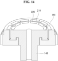
- FIG. 14 is a view schematically illustrating a first gear according to a second embodiment of the disclosure.
- the plurality of first magnet units of the first magnet 210 disposed on the first gear 140 may be spaced apart from each other in the circumferential direction, and the plurality of second magnet units of the second magnet 220 may be spaced apart from each other in the circumferential direction.
- the plurality of first magnet units of the first magnet 210 may be individually mounted in a plurality of grooves formed in the inner surface of the outer part 143.
- the plurality of second magnet units of the second magnet 220 may be individually mounted in a plurality of grooves formed in the outer surface of the inner part 143.
- the second embodiment of the disclosure may enhance the stability of the product by increasing the coupling force of the magnets 200 to the first gear 140 as compared to the first embodiment.
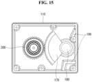
- FIG. 15 is a cross-sectional view illustrating a valve actuator according to a third embodiment of the disclosure.
- a valve actuator may include a housing 110, a motor 120 disposed on the housing 110, a drive gear 300 coupled to a motor shaft of the motor 120, an output gear 170 coupled to an output shaft 180 and engaging with the drive gear 300, and a stopper 190 disposed in the housing 110 and limiting a rotation radius of the output gear 170.
- valve actuator according to the third embodiment of the disclosure omits the transfer gears 140, 150, and 160 of the valve actuator 20, and the magnets 200 are installed in the drive gear 130.
- the drive gear 300 may be coupled to the motor shaft of the motor 120 and may be rotated in a first direction or second direction by the motor 120.
- the drive gear 300 may engage with the output gear 170 to rotate the output gear 170 at a predetermined gear ratio.
- the drive gear 300 may include an outer part, an inner part disposed inside the outer part, a first magnet disposed on the outer part, and a second magnet disposed on the inner part and facing the first magnet.
- the inner part of the drive gear 300 may be coupled to the motor shaft of the motor 120, and the outer part of the drive gear 300 may engage with the output gear 170.
- the inner part of the drive gear 300 idles with respect to the outer part 143 of the drive gear 300 due to the first magnet and the second magnet of the drive gear 300, preventing damage to the drive gear 300 and the output gear 170.
- the inner part of the drive gear 300 idles with respect to the outer part of the drive gear 300 due to the first magnet and the second magnet of the drive gear 300, damping the torque of the motor 120 applied due to the over-output and hence preventing damage to the drive gear 130 and the output gear 170.
- the inner part of the drive gear 300 may be coupled to the motor shaft of the motor 120 to rotate together with the motor shaft.
- the upper end or the lower end of the outer part of the drive gear 300 may be vertically supported by the inner part of the drive gear 300.
- the height of the first magnet of the drive gear 300 is larger than the height of the second magnet of the drive gear 300.
- a vertical center of the first magnet of the drive gear 300 may be disposed above a vertical center of the second magnet of the drive gear 300.
- a vertical center of the first magnet of the drive gear 300 may be disposed below a vertical center of the second magnet of the drive gear 300.
- the inner part of the drive gear 300 may include a groove formed in an area supporting the upper end or the lower end of the outer part of the drive gear 300.
- Lubricant may be placed in the groove. The lubricant may perform lubrication to prevent damage to the components under the high-speed slip condition.
- FIG. 16 is a perspective view illustrating some components of a valve actuator according to a fourth embodiment of the disclosure.
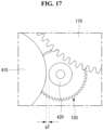
- FIG. 17 is a plan view illustrating some components of a valve actuator according to the fourth embodiment of the disclosure.
- a valve actuator may include a housing 110, a motor 120 disposed on the housing 110, a drive gear 130 coupled to a motor shaft of the motor 120, transfer gears 140 and 150 engaging with the drive gear 130 and rotating according to a first gear ratio when the drive gear 130 rotates, an output gear 170 coupled to an output shaft 180 and engaging with the transfer gears 140 and 150, and a stopper 190 disposed in the housing 110 and limiting a rotation radius of the output gear 170.
- the transfer gears 140 and 150 may include a first transfer gear 140, which engages with the drive gear 130 and rotates according to a first gear ratio with respect to the drive gear 130 when the drive gear 130 rotates, and a second transfer gear 150, which rotates according to a second gear ratio with respect to the first transfer gear 140 when the first transfer gear 140 rotates.
- the second transfer gear 150 may engage with the output gear 170.
- the transfer gears 140 and 150 may include a cylindrical first magnet 410 disposed on the first transfer gear 140 and a cylindrical second magnet 420 disposed on the second transfer gear 150.
- the first magnet 410 may be horizontally spaced apart from the second magnet 420.
- a predetermined gap g2 may be formed between the first magnet 410 and the second magnet 420.
- the first magnet 410 and the second magnet 420 may overlap each other in a horizontal direction.
- the first transfer gear 140 idles with respect to the second transfer gear 150 due to the first magnet 410 and the second magnet 420, preventing damage to the drive gear 130, the transfer gears 140 and 150, and the output gear 170.
- the first transfer gear 140 idles with respect to the second transfer gear 150 due to the first magnet 410 and the second magnet 420, damping the torque of the motor 120 applied due to the over-output and hence preventing damage to the drive gear 130, the transfer gears 140 and 150, and the output gear 170.
- the first magnet 410 may include a plurality of first magnet units arranged in a circumferential direction
- the second magnet 420 may include a plurality of second magnet units arranged in a circumferential direction.
- the plurality of first magnet units may be magnetized to have different poles from neighboring magnet units, and the plurality of second magnet units may be magnetized to have different poles from neighboring magnet units.
- the first magnet unit and the second magnet unit facing each other, among the plurality of first magnet units and the plurality of second magnet units, may have different polarities.
- the ratio of the number of the plurality of first magnet units to the number of the plurality of second magnet units may be identical to the second gear ratio.
- a valve actuator may include a housing 110, a motor 120 disposed on the housing 110, a drive gear 130 coupled to a motor shaft of the motor 120, a cylindrical first magnet 410 coupled to the drive gear 130, an output gear 170 coupled to an output shaft 180, a cylindrical second magnet 420 coupled to the output gear 170, and a stopper 190 disposed in the housing 110 and limiting a rotation radius of the output gear 170.
- valve actuator according to the fifth embodiment of the disclosure omits the transfer gears 140 and 150 of the valve actuator according to the fourth embodiment of the disclosure, and the first magnet 410 is coupled to the drive gear 130, and the second magnet 420 is coupled to the output gear 170.
Landscapes
- Engineering & Computer Science (AREA)
- General Engineering & Computer Science (AREA)
- Mechanical Engineering (AREA)
- Physics & Mathematics (AREA)
- Electromagnetism (AREA)
- Power Engineering (AREA)
- Connection Of Motors, Electrical Generators, Mechanical Devices, And The Like (AREA)
Claims (9)
- Ventilaktuator, aufweisend:ein Gehäuse (110);einen Motor (120), der an dem Gehäuse (110) angeordnet ist;ein Antriebszahnrad (130), das mit einer Motorwelle des Motors (120) gekoppelt ist;ein Verteilergetriebe (140, 150, 160), das mit dem Antriebszahnrad (130) in Eingriff steht und sich gemäß einem vorbestimmten Übersetzungsverhältnis dreht, wenn sich das Antriebszahnrad (130) dreht;ein Abtriebszahnrad (170), das mit einer Abtriebswelle (180) gekoppelt ist und mit dem Verteilergetriebe (140, 150, 160) in Eingriff steht; undeine Sperre (190), die in dem Gehäuse (110) angeordnet ist und eine Drehung des Abtriebszahnrads (170) begrenzt,dadurch gekennzeichnet, dass das Verteilergetriebe (140, 150, 160) ein Außenteil (141), ein in dem Außenteil (141) angeordnetes Innenteil (143), einen an dem Außenteil (141) angeordneten ersten Magneten (210) und einen an dem Innenteil (143) angeordneten und dem ersten Magneten (210) gegenüberliegenden zweiten Magneten (220) umfasst, unddass ein oberes Ende und ein unteres Ende des Innenteils (143) von einer Innenfläche des Gehäuses (110) abgestützt werden und ein oberes oder ein unteres Ende des Außenteils (141) vertikal von dem Innenteil (143) abgestützt wird und eine Höhe des ersten Magneten (210) größer als eine Höhe des zweiten Magneten (220) ist.
- Ventilaktuator nach Anspruch 1, wobei der erste Magnet (210) und der zweite Magnet (220) unterschiedliche Polaritäten aufweisen.
- Ventilaktuator nach Anspruch 1 oder 2, wobei eine Anziehungskraft zwischen dem ersten Magneten (210) und dem zweiten Magneten (220) größer als eine durchschnittliche Ausgangskraft des Motors (120) und kleiner als eine maximale Ausgangskraft des Motors (120) ist.
- Ventilaktuator nach einem der vorhergehenden Ansprüche, wobei der erste Magnet (210) eine Vielzahl von ersten Magneteinheiten (212, 214, 216, 218) mit unterschiedlichen Polaritäten zwischen benachbarten Magneteinheiten umfasst, und der zweite Magnet (220) eine Vielzahl von zweiten Magneteinheiten (222, 224, 226, 228) mit unterschiedlichen Polaritäten zwischen benachbarten Magneteinheiten umfasst, die der Vielzahl von ersten Magneteinheiten (212, 214, 216, 218) einzeln gegenüberliegen.
- Ventilaktuator nach einem der vorhergehenden Ansprüche, wobei der Motor (120) ein Gleichstrommotor ist.
- Ventilaktuator nach einem der vorhergehenden Ansprüche, wobei dann, wenn das obere Ende des Außenteils (141) vertikal von dem Innenteil (143) abgestützt wird, eine vertikale Mitte des ersten Magneten (210) oberhalb einer vertikalen Mitte des zweiten Magneten (220) angeordnet ist, und
wobei dann, wenn das untere Ende des Außenteils (141) vertikal von dem Innenteil (143) abgestützt wird, die vertikale Mitte des ersten Magneten (210) unterhalb der vertikalen Mitte des zweiten Magneten (220) angeordnet ist. - Ventilaktuator nach einem der vorhergehenden Ansprüche, wobei das Innenteil (143) eine Nut (1431, 1433) aufweist, die in einem Bereich ausgebildet ist, der das obere Ende oder das untere Ende des Außenteils (141) abstützt.
- Ventilaktuator nach Anspruch 7, wobei in der Nut (1431, 1433) ein Schmiermittel angeordnet ist.
- Ventilaktuator nach einem der vorhergehenden Ansprüche, wobei das Verteilergetriebe (140, 150, 160) umfasst:ein erstes Zahnrad (140), das mit dem Antriebszahnrad (130) in Eingriff steht,ein zweites Zahnrad (150), das mit dem ersten Zahnrad (140) in Eingriff steht, undein drittes Zahnrad (160), das mit dem zweiten Zahnrad (150) in Eingriff steht, undwobei das erste Zahnrad (140) das Außenteil (141), das Innenteil (143), den ersten Magneten (210) und den zweiten Magneten (220) umfasst.
Applications Claiming Priority (1)
| Application Number | Priority Date | Filing Date | Title |
|---|---|---|---|
| KR1020210110070A KR102565392B1 (ko) | 2021-08-20 | 2021-08-20 | 밸브 액츄에이터 |
Publications (2)
| Publication Number | Publication Date |
|---|---|
| EP4137727A1 EP4137727A1 (de) | 2023-02-22 |
| EP4137727B1 true EP4137727B1 (de) | 2024-11-13 |
Family
ID=79185807
Family Applications (1)
| Application Number | Title | Priority Date | Filing Date |
|---|---|---|---|
| EP21218051.7A Active EP4137727B1 (de) | 2021-08-20 | 2021-12-29 | Ventilaktuator |
Country Status (3)
| Country | Link |
|---|---|
| US (1) | US12104714B2 (de) |
| EP (1) | EP4137727B1 (de) |
| KR (1) | KR102565392B1 (de) |
Family Cites Families (14)
| Publication number | Priority date | Publication date | Assignee | Title |
|---|---|---|---|---|
| US4754949A (en) * | 1987-09-08 | 1988-07-05 | Rikuo Fukamachi | Actuator for valve |
| US4808869A (en) * | 1987-11-18 | 1989-02-28 | Sundstrand Corp. | Integral magnetic torque limiting coupling/motor |
| US6098957A (en) * | 1998-07-31 | 2000-08-08 | Honeywell Inc. | Electro-mechanical torque limiter for valve actuators |
| US6097123A (en) * | 1999-06-03 | 2000-08-01 | Johnson Controls Technology Company | Brake and stall detector for a motorized actuator |
| US6173939B1 (en) * | 1999-11-10 | 2001-01-16 | Ford Global Technologies, Inc. | Electronic throttle control system with two-spring failsafe mechanism |
| JP3742855B2 (ja) * | 2000-03-14 | 2006-02-08 | ダイキン工業株式会社 | ロータリ式四路弁 |
| KR100392198B1 (ko) | 2001-07-02 | 2003-07-22 | 주식회사 코텍 | 전동 볼밸브 |
| KR20070070498A (ko) * | 2005-12-29 | 2007-07-04 | 세메스 주식회사 | 밸브 및 상기 밸브 내 유체 흐름을 제어하는 방법 |
| JP2009138856A (ja) * | 2007-12-06 | 2009-06-25 | Tgk Co Ltd | 電動弁 |
| CN101766914A (zh) * | 2009-01-07 | 2010-07-07 | 鸿富锦精密工业(深圳)有限公司 | 传动装置 |
| WO2016002599A1 (ja) * | 2014-06-30 | 2016-01-07 | 愛三工業株式会社 | 二重偏心弁 |
| KR101611977B1 (ko) * | 2014-10-10 | 2016-04-12 | 주식회사 현대케피코 | 충격 흡수형 스토퍼가 장착된 액추에이터 |
| KR101616578B1 (ko) | 2015-01-23 | 2016-04-28 | 캄텍주식회사 | 차량용 액츄에이터 |
| JP6859233B2 (ja) * | 2017-08-31 | 2021-04-14 | 愛三工業株式会社 | 二重偏心弁 |
-
2021
- 2021-08-20 KR KR1020210110070A patent/KR102565392B1/ko active Active
- 2021-12-29 EP EP21218051.7A patent/EP4137727B1/de active Active
-
2022
- 2022-01-06 US US17/570,130 patent/US12104714B2/en active Active
Also Published As
| Publication number | Publication date |
|---|---|
| KR102565392B1 (ko) | 2023-08-09 |
| KR20230027834A (ko) | 2023-02-28 |
| US12104714B2 (en) | 2024-10-01 |
| EP4137727A1 (de) | 2023-02-22 |
| CN115929980A (zh) | 2023-04-07 |
| US20230057656A1 (en) | 2023-02-23 |
Similar Documents
| Publication | Publication Date | Title |
|---|---|---|
| CN104033384A (zh) | 涡旋式压缩机 | |
| EP3561302A1 (de) | Mitrotierender spiralverdichter | |
| JP5150319B2 (ja) | バルブ用アクチュエータ | |
| EP4160063B1 (de) | Ventilaktuator | |
| CN111433477B (zh) | 电磁离合器及变速箱 | |
| EP4137727A1 (de) | Ventilaktuator | |
| EP2893231B1 (de) | Magnetisches haltebremse sowie betätigungsvorrichtung mit einer magnetischen haltebremse | |
| EP1552177B1 (de) | Kupplung mit einem fluid mit variabler viskosität | |
| JPWO2019026340A1 (ja) | 真空ポンプ | |
| US7246579B2 (en) | Actuator for valve lift controller | |
| CN115929980B (zh) | 阀致动器 | |
| WO2018116685A1 (ja) | スクロール型圧縮機 | |
| JP2007285483A (ja) | 送りねじ機構を備えるアクチュエータ | |
| US20240102516A1 (en) | Geared motor and clutch actuator using same | |
| US7234425B2 (en) | Actuator for valve lift controller | |
| CN112701875B (zh) | 环板式永磁齿轮变速传动装置 | |
| KR20200004748A (ko) | 스크롤 압축기 | |
| RU2362260C2 (ru) | Электромагнитный двигатель постоянного тока | |
| JP2025150346A (ja) | 電動アクチュエータ、およびアクチュエータ装置 | |
| WO2019082123A1 (en) | ELECTRIC MOTOR HIGH TORQUE PLATE | |
| JP6762610B2 (ja) | ブラシレスモータ | |
| CN2879517Y (zh) | 磁力离合器 | |
| CN1945945A (zh) | 磁力离合器 | |
| JPH11287260A (ja) | 一方向クラッチ | |
| CN114060276A (zh) | 压缩机 |
Legal Events
| Date | Code | Title | Description |
|---|---|---|---|
| PUAI | Public reference made under article 153(3) epc to a published international application that has entered the european phase |
Free format text: ORIGINAL CODE: 0009012 |
|
| STAA | Information on the status of an ep patent application or granted ep patent |
Free format text: STATUS: REQUEST FOR EXAMINATION WAS MADE |
|
| 17P | Request for examination filed |
Effective date: 20220129 |
|
| AK | Designated contracting states |
Kind code of ref document: A1 Designated state(s): AL AT BE BG CH CY CZ DE DK EE ES FI FR GB GR HR HU IE IS IT LI LT LU LV MC MK MT NL NO PL PT RO RS SE SI SK SM TR |
|
| GRAP | Despatch of communication of intention to grant a patent |
Free format text: ORIGINAL CODE: EPIDOSNIGR1 |
|
| STAA | Information on the status of an ep patent application or granted ep patent |
Free format text: STATUS: GRANT OF PATENT IS INTENDED |
|
| RIC1 | Information provided on ipc code assigned before grant |
Ipc: H02K 49/10 20060101ALI20240724BHEP Ipc: F16K 31/08 20060101ALI20240724BHEP Ipc: F16H 19/00 20060101ALI20240724BHEP Ipc: F16H 37/04 20060101ALI20240724BHEP Ipc: F16K 47/00 20060101ALI20240724BHEP Ipc: F16H 35/10 20060101ALI20240724BHEP Ipc: F16K 31/53 20060101AFI20240724BHEP |
|
| INTG | Intention to grant announced |
Effective date: 20240805 |
|
| GRAS | Grant fee paid |
Free format text: ORIGINAL CODE: EPIDOSNIGR3 |
|
| GRAA | (expected) grant |
Free format text: ORIGINAL CODE: 0009210 |
|
| STAA | Information on the status of an ep patent application or granted ep patent |
Free format text: STATUS: THE PATENT HAS BEEN GRANTED |
|
| AK | Designated contracting states |
Kind code of ref document: B1 Designated state(s): AL AT BE BG CH CY CZ DE DK EE ES FI FR GB GR HR HU IE IS IT LI LT LU LV MC MK MT NL NO PL PT RO RS SE SI SK SM TR |
|
| REG | Reference to a national code |
Ref country code: GB Ref legal event code: FG4D |
|
| REG | Reference to a national code |
Ref country code: CH Ref legal event code: EP |
|
| REG | Reference to a national code |
Ref country code: IE Ref legal event code: FG4D |
|
| REG | Reference to a national code |
Ref country code: DE Ref legal event code: R096 Ref document number: 602021021739 Country of ref document: DE |
|
| REG | Reference to a national code |
Ref country code: LT Ref legal event code: MG9D |
|
| REG | Reference to a national code |
Ref country code: NL Ref legal event code: MP Effective date: 20241113 |
|
| PG25 | Lapsed in a contracting state [announced via postgrant information from national office to epo] |
Ref country code: HR Free format text: LAPSE BECAUSE OF FAILURE TO SUBMIT A TRANSLATION OF THE DESCRIPTION OR TO PAY THE FEE WITHIN THE PRESCRIBED TIME-LIMIT Effective date: 20241113 Ref country code: IS Free format text: LAPSE BECAUSE OF FAILURE TO SUBMIT A TRANSLATION OF THE DESCRIPTION OR TO PAY THE FEE WITHIN THE PRESCRIBED TIME-LIMIT Effective date: 20250313 Ref country code: PT Free format text: LAPSE BECAUSE OF FAILURE TO SUBMIT A TRANSLATION OF THE DESCRIPTION OR TO PAY THE FEE WITHIN THE PRESCRIBED TIME-LIMIT Effective date: 20250313 |
|
| PG25 | Lapsed in a contracting state [announced via postgrant information from national office to epo] |
Ref country code: NL Free format text: LAPSE BECAUSE OF FAILURE TO SUBMIT A TRANSLATION OF THE DESCRIPTION OR TO PAY THE FEE WITHIN THE PRESCRIBED TIME-LIMIT Effective date: 20241113 Ref country code: FI Free format text: LAPSE BECAUSE OF FAILURE TO SUBMIT A TRANSLATION OF THE DESCRIPTION OR TO PAY THE FEE WITHIN THE PRESCRIBED TIME-LIMIT Effective date: 20241113 |
|
| REG | Reference to a national code |
Ref country code: AT Ref legal event code: MK05 Ref document number: 1741906 Country of ref document: AT Kind code of ref document: T Effective date: 20241113 |
|
| PG25 | Lapsed in a contracting state [announced via postgrant information from national office to epo] |
Ref country code: BG Free format text: LAPSE BECAUSE OF FAILURE TO SUBMIT A TRANSLATION OF THE DESCRIPTION OR TO PAY THE FEE WITHIN THE PRESCRIBED TIME-LIMIT Effective date: 20241113 |
|
| PG25 | Lapsed in a contracting state [announced via postgrant information from national office to epo] |
Ref country code: ES Free format text: LAPSE BECAUSE OF FAILURE TO SUBMIT A TRANSLATION OF THE DESCRIPTION OR TO PAY THE FEE WITHIN THE PRESCRIBED TIME-LIMIT Effective date: 20241113 |
|
| PG25 | Lapsed in a contracting state [announced via postgrant information from national office to epo] |
Ref country code: NO Free format text: LAPSE BECAUSE OF FAILURE TO SUBMIT A TRANSLATION OF THE DESCRIPTION OR TO PAY THE FEE WITHIN THE PRESCRIBED TIME-LIMIT Effective date: 20250213 |
|
| PG25 | Lapsed in a contracting state [announced via postgrant information from national office to epo] |
Ref country code: LV Free format text: LAPSE BECAUSE OF FAILURE TO SUBMIT A TRANSLATION OF THE DESCRIPTION OR TO PAY THE FEE WITHIN THE PRESCRIBED TIME-LIMIT Effective date: 20241113 Ref country code: GR Free format text: LAPSE BECAUSE OF FAILURE TO SUBMIT A TRANSLATION OF THE DESCRIPTION OR TO PAY THE FEE WITHIN THE PRESCRIBED TIME-LIMIT Effective date: 20250214 Ref country code: AT Free format text: LAPSE BECAUSE OF FAILURE TO SUBMIT A TRANSLATION OF THE DESCRIPTION OR TO PAY THE FEE WITHIN THE PRESCRIBED TIME-LIMIT Effective date: 20241113 |
|
| PG25 | Lapsed in a contracting state [announced via postgrant information from national office to epo] |
Ref country code: PL Free format text: LAPSE BECAUSE OF FAILURE TO SUBMIT A TRANSLATION OF THE DESCRIPTION OR TO PAY THE FEE WITHIN THE PRESCRIBED TIME-LIMIT Effective date: 20241113 |
|
| PG25 | Lapsed in a contracting state [announced via postgrant information from national office to epo] |
Ref country code: RS Free format text: LAPSE BECAUSE OF FAILURE TO SUBMIT A TRANSLATION OF THE DESCRIPTION OR TO PAY THE FEE WITHIN THE PRESCRIBED TIME-LIMIT Effective date: 20250213 |
|
| PG25 | Lapsed in a contracting state [announced via postgrant information from national office to epo] |
Ref country code: SM Free format text: LAPSE BECAUSE OF FAILURE TO SUBMIT A TRANSLATION OF THE DESCRIPTION OR TO PAY THE FEE WITHIN THE PRESCRIBED TIME-LIMIT Effective date: 20241113 |
|
| PG25 | Lapsed in a contracting state [announced via postgrant information from national office to epo] |
Ref country code: DK Free format text: LAPSE BECAUSE OF FAILURE TO SUBMIT A TRANSLATION OF THE DESCRIPTION OR TO PAY THE FEE WITHIN THE PRESCRIBED TIME-LIMIT Effective date: 20241113 |
|
| PG25 | Lapsed in a contracting state [announced via postgrant information from national office to epo] |
Ref country code: EE Free format text: LAPSE BECAUSE OF FAILURE TO SUBMIT A TRANSLATION OF THE DESCRIPTION OR TO PAY THE FEE WITHIN THE PRESCRIBED TIME-LIMIT Effective date: 20241113 |
|
| PG25 | Lapsed in a contracting state [announced via postgrant information from national office to epo] |
Ref country code: RO Free format text: LAPSE BECAUSE OF FAILURE TO SUBMIT A TRANSLATION OF THE DESCRIPTION OR TO PAY THE FEE WITHIN THE PRESCRIBED TIME-LIMIT Effective date: 20241113 |
|
| PG25 | Lapsed in a contracting state [announced via postgrant information from national office to epo] |
Ref country code: SK Free format text: LAPSE BECAUSE OF FAILURE TO SUBMIT A TRANSLATION OF THE DESCRIPTION OR TO PAY THE FEE WITHIN THE PRESCRIBED TIME-LIMIT Effective date: 20241113 |
|
| PG25 | Lapsed in a contracting state [announced via postgrant information from national office to epo] |
Ref country code: CZ Free format text: LAPSE BECAUSE OF FAILURE TO SUBMIT A TRANSLATION OF THE DESCRIPTION OR TO PAY THE FEE WITHIN THE PRESCRIBED TIME-LIMIT Effective date: 20241113 |
|
| PG25 | Lapsed in a contracting state [announced via postgrant information from national office to epo] |
Ref country code: IT Free format text: LAPSE BECAUSE OF FAILURE TO SUBMIT A TRANSLATION OF THE DESCRIPTION OR TO PAY THE FEE WITHIN THE PRESCRIBED TIME-LIMIT Effective date: 20241113 |
|
| REG | Reference to a national code |
Ref country code: CH Ref legal event code: PL |
|
| REG | Reference to a national code |
Ref country code: DE Ref legal event code: R097 Ref document number: 602021021739 Country of ref document: DE |
|
| PG25 | Lapsed in a contracting state [announced via postgrant information from national office to epo] |
Ref country code: LU Free format text: LAPSE BECAUSE OF NON-PAYMENT OF DUE FEES Effective date: 20241229 |
|
| PG25 | Lapsed in a contracting state [announced via postgrant information from national office to epo] |
Ref country code: SE Free format text: LAPSE BECAUSE OF FAILURE TO SUBMIT A TRANSLATION OF THE DESCRIPTION OR TO PAY THE FEE WITHIN THE PRESCRIBED TIME-LIMIT Effective date: 20241113 |
|
| PG25 | Lapsed in a contracting state [announced via postgrant information from national office to epo] |
Ref country code: MC Free format text: LAPSE BECAUSE OF FAILURE TO SUBMIT A TRANSLATION OF THE DESCRIPTION OR TO PAY THE FEE WITHIN THE PRESCRIBED TIME-LIMIT Effective date: 20241113 |
|
| PLBE | No opposition filed within time limit |
Free format text: ORIGINAL CODE: 0009261 |
|
| STAA | Information on the status of an ep patent application or granted ep patent |
Free format text: STATUS: NO OPPOSITION FILED WITHIN TIME LIMIT |
|
| REG | Reference to a national code |
Ref country code: BE Ref legal event code: MM Effective date: 20241231 |
|
| PG25 | Lapsed in a contracting state [announced via postgrant information from national office to epo] |
Ref country code: BE Free format text: LAPSE BECAUSE OF NON-PAYMENT OF DUE FEES Effective date: 20241231 |
|
| PG25 | Lapsed in a contracting state [announced via postgrant information from national office to epo] |
Ref country code: CH Free format text: LAPSE BECAUSE OF NON-PAYMENT OF DUE FEES Effective date: 20241231 |
|
| 26N | No opposition filed |
Effective date: 20250814 |
|
| PG25 | Lapsed in a contracting state [announced via postgrant information from national office to epo] |
Ref country code: IE Free format text: LAPSE BECAUSE OF NON-PAYMENT OF DUE FEES Effective date: 20241229 |
|
| PGFP | Annual fee paid to national office [announced via postgrant information from national office to epo] |
Ref country code: DE Payment date: 20251105 Year of fee payment: 5 |
|
| PGFP | Annual fee paid to national office [announced via postgrant information from national office to epo] |
Ref country code: FR Payment date: 20251111 Year of fee payment: 5 |
|
| PG25 | Lapsed in a contracting state [announced via postgrant information from national office to epo] |
Ref country code: CY Free format text: LAPSE BECAUSE OF FAILURE TO SUBMIT A TRANSLATION OF THE DESCRIPTION OR TO PAY THE FEE WITHIN THE PRESCRIBED TIME-LIMIT Effective date: 20241113 |