EP4137440B1 - Plaque de base pour un chariot autonome de manutention - Google Patents
Plaque de base pour un chariot autonome de manutention Download PDFInfo
- Publication number
- EP4137440B1 EP4137440B1 EP22188530.4A EP22188530A EP4137440B1 EP 4137440 B1 EP4137440 B1 EP 4137440B1 EP 22188530 A EP22188530 A EP 22188530A EP 4137440 B1 EP4137440 B1 EP 4137440B1
- Authority
- EP
- European Patent Office
- Prior art keywords
- base plate
- industrial truck
- arrangement
- width direction
- respect
- Prior art date
- Legal status (The legal status is an assumption and is not a legal conclusion. Google has not performed a legal analysis and makes no representation as to the accuracy of the status listed.)
- Active
Links
Images
Classifications
-
- B—PERFORMING OPERATIONS; TRANSPORTING
- B66—HOISTING; LIFTING; HAULING
- B66F—HOISTING, LIFTING, HAULING OR PUSHING, NOT OTHERWISE PROVIDED FOR, e.g. DEVICES WHICH APPLY A LIFTING OR PUSHING FORCE DIRECTLY TO THE SURFACE OF A LOAD
- B66F9/00—Devices for lifting or lowering bulky or heavy goods for loading or unloading purposes
- B66F9/06—Devices for lifting or lowering bulky or heavy goods for loading or unloading purposes movable, with their loads, on wheels or the like, e.g. fork-lift trucks
- B66F9/075—Constructional features or details
- B66F9/07513—Details concerning the chassis
-
- B—PERFORMING OPERATIONS; TRANSPORTING
- B66—HOISTING; LIFTING; HAULING
- B66F—HOISTING, LIFTING, HAULING OR PUSHING, NOT OTHERWISE PROVIDED FOR, e.g. DEVICES WHICH APPLY A LIFTING OR PUSHING FORCE DIRECTLY TO THE SURFACE OF A LOAD
- B66F9/00—Devices for lifting or lowering bulky or heavy goods for loading or unloading purposes
- B66F9/06—Devices for lifting or lowering bulky or heavy goods for loading or unloading purposes movable, with their loads, on wheels or the like, e.g. fork-lift trucks
- B66F9/075—Constructional features or details
- B66F9/12—Platforms; Forks; Other load supporting or gripping members
-
- B—PERFORMING OPERATIONS; TRANSPORTING
- B66—HOISTING; LIFTING; HAULING
- B66F—HOISTING, LIFTING, HAULING OR PUSHING, NOT OTHERWISE PROVIDED FOR, e.g. DEVICES WHICH APPLY A LIFTING OR PUSHING FORCE DIRECTLY TO THE SURFACE OF A LOAD
- B66F9/00—Devices for lifting or lowering bulky or heavy goods for loading or unloading purposes
- B66F9/06—Devices for lifting or lowering bulky or heavy goods for loading or unloading purposes movable, with their loads, on wheels or the like, e.g. fork-lift trucks
- B66F9/063—Automatically guided
Definitions
- the present invention relates to a base plate for an autonomously guided industrial truck with a longitudinal and a width direction, which is intended to form a base plate arrangement and to partially delimit a vehicle body of the industrial truck downwards, and which comprises a plate body which is intended to define an outline of the base plate arrangement at least partially.
- a steerable drive roller and side support rollers must usually be attached or integrated to the underside of the vehicle body of such vehicles, which contribute to the safe standing and stable travel of the industrial truck even when loaded.
- An example of a base plate of an autonomous industrial truck according to the preamble of claim 1 is known from CN 206 606 990 U known.
- a generic base plate for an autonomously guided industrial truck of the type mentioned at the outset should have a central opening with respect to the width direction, which is intended to receive a drive wheel of the industrial truck, and at least one recess offset in the width direction with respect to a longitudinal central axis, which is intended to receive a support wheel arrangement of the industrial truck.
- a base plate By providing a central opening in the base plate in this way, which can accommodate a drive wheel of the industrial truck in such a way that it protrudes through the central opening and can be pivoted in particular within the opening to steer the industrial truck, while at least one support wheel arrangement can also be accommodated in the at least one recess outside the longitudinal central axis, a base plate can be created which on the one hand allows functional components of the industrial truck to be arranged at a low height above the driving surface, in particular the scanner unit already mentioned, while on the other hand a solid closure of the vehicle body at the bottom is created, which on the one hand protects all components of the industrial truck arranged there from impacts and damage, while on the other hand helping to keep the center of gravity of the industrial truck as low as possible.
- the base plate according to the invention can indeed be formed in one piece as a solid monolithic metal part, it should not be excluded at this point that such a one-piece base plate is also composed of several sub-units in an inseparable manner, for example welded.
- Such a base plate which has a central opening for a drive wheel and at least one offset recess for a support wheel, the latter preferably also being attached to the base plate, thus makes it possible on the one hand to positively influence the center of gravity of the industrial truck, and on the other hand means an optimization of the structure of the industrial truck with regard to sensors arranged on the industrial truck.
- Known support wheel designs are either attached above the support wheel to a sheet metal frame construction or by means of a swing arm, which is usually arranged on the side of the frame.
- the laser scanners generally used for environmental monitoring protrude into the scanning plane, which must be at a certain distance from the ground surface, so that the laser scanners in the prior art had to be arranged outside the vehicle geometry and thus widened the industrial truck in an undesirable way.
- the base plate according to the invention comprises two recesses for each support wheel arrangement, which are arranged symmetrically with respect to the longitudinal center axis.
- the at least one recess can be provided on the base plate according to the invention in such a way that it defines part of the outline of the plate body.
- the respective support wheel arrangement when mounted on the plate body, partially forms part of the outline of this assembly and thus represents a closure at one edge thereof.
- the largest possible track width of the support wheel arrangement can be achieved, whereby, particularly in embodiments with a symmetrically arranged pair of support wheel arrangements, stable driving behavior can be achieved even at high cornering speeds of the industrial truck.
- the at least one recess in a front corner region of the plate body in relation to the longitudinal direction and an outer corner region in relation to the width direction defines the outline thereof, so that the respective support wheel arrangement in its assembled state forms the corresponding corner of the base plate arrangement.
- the base plate according to the invention can also have at least one further recess which is intended to accommodate a scanner unit in sections. While such scanner units must be arranged in an operating state of the operational industrial truck in such a way that that their scanning plane extends above the base plate, some types of scanner units available on the market have an increased height, which may make it desirable to partially embed them in the base plate in order to minimize the effective height above the base plate for the scanner unit.
- the at least one further recess for a scanner unit may be located completely within the outline of the base plate, so that there is always material of the plate body outside of it, particularly in the width direction, which can protect the sensitive scanner unit from lateral impacts or other potential dangers.
- the additional recesses provided for the scanner units it may also be desirable if these are arranged in pairs symmetrically with respect to the longitudinal center axis of the base plate according to the invention. In this way, symmetrical monitoring of both sides of the industrial truck can be achieved, which, compared to an asymmetrical arrangement of scanner units, can enable simplified handling of the corresponding data and facilitate all-round monitoring.
- the base plate according to the invention can have a support surface in its rear region in the longitudinal direction and central region in the width direction, which is intended to support a lifting cylinder of the industrial truck.
- the base plate according to the invention also offers an optimal interface point for the attachment of this lifting cylinder, since its design enables it to easily absorb and support the corresponding forces.
- the base plate has a maximum width of about 800mm or less. These dimensions correspond exactly to the width of a Euro pallet, so that the corresponding industrial truck can be easily maneuvered between Euro pallets placed next to each other on the driving surface.
- variants of the base plate according to the invention with larger dimensions for other corresponding applications are also conceivable.
- the base plate according to the invention Since both the steerability of the drive wheel of the industrial truck and the commonly used support wheel arrangements and some types of scanner units each require circular symmetry for their assembly, it can be advantageous in the base plate according to the invention if the central opening and/or at least one of the recesses and/or at least one of the further recesses is essentially circular.
- the at least one recess defines part of the outline of the plate body, this feature is of course to be understood in such a way that the section of the corresponding recess which borders on the outline of the plate body forms a section of a circle, while the support wheel arrangement itself can define the circular shape over the remaining section.
- the present invention further relates to a base plate arrangement for an autonomously guided industrial truck, comprising a base plate according to the invention of the type just described and at least one support wheel arrangement accommodated in the recess or one of the recesses.
- a base plate arrangement for an autonomously guided industrial truck comprising a base plate according to the invention of the type just described and at least one support wheel arrangement accommodated in the recess or one of the recesses.
- the construction type and the external dimensions of the corresponding support wheel arrangement must be adapted to the respective recess, wherein the at least one support wheel arrangement and the base plate on their upper sides can be designed essentially flush with each other or the base plate can extend upwards beyond the at least one support wheel arrangement.
- the base plate arrangement according to the invention can further comprise at least one scanner unit, which is arranged such that its scanning plane lies above the base plate, wherein the at least one scanner unit is optionally accommodated in sections in the or one of the further recesses.
- the at least one scanner unit is optionally accommodated in sections in the or one of the further recesses.
- the base plate protects the at least one scanner unit from objects below the scanning plane.
- two load arms for carrying load wheels can be firmly attached to it, in particular welded on, whereby the load arms can optionally extend on both sides of the contact surface and can, for example, be arranged flush with it. Accordingly, a force-conducting interface for the load arms can also be created at this point, so that the transmission of forces and moments is possible in the industrial truck in a reliable manner from this point of view.
- the present invention relates to a vehicle body of an autonomously guided industrial truck, which comprises a base plate arrangement of the type just described and a vehicle frame arranged above the base plate, wherein an interface for connecting the base plate arrangement and the vehicle frame is placed such that it is arranged outside the central opening, but spaced apart from the outline of the base plate in the width direction.
- a vehicle body of an autonomously guided industrial truck which comprises a base plate arrangement of the type just described and a vehicle frame arranged above the base plate, wherein an interface for connecting the base plate arrangement and the vehicle frame is placed such that it is arranged outside the central opening, but spaced apart from the outline of the base plate in the width direction.
- the at least one recess and optionally the at least one further recess in the width direction can be arranged outside the interface with respect to the longitudinal center axis.
- the present invention relates to an autonomously guided industrial truck which comprises such a vehicle body.
- Any other functional units of the industrial truck can be arranged within the vehicle frame of this vehicle body, for example control and communication units, other sensor units and energy storage units which are required for the operation of the industrial truck.
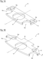
- Fig. 1A and 1B show two variants of base plates according to the invention for autonomously guided industrial trucks, which are designated with the reference numerals 10 and 10' respectively. It should be noted that identical or equivalent elements of the variant from Fig. 1B each with the same reference numerals as the corresponding elements of Fig. 1A , additionally marked with an apostrophe.
- the base plates 10 and 10' each have a longitudinal direction or longitudinal center axis L and a width direction B perpendicular thereto, which are oriented in the same way as the corresponding directions are usually designated in industrial trucks equipped with such base plates.
- the base plates 10 and 10' are each intended to form a base plate arrangement of an industrial truck and to limit a vehicle body of this industrial truck in sections at the bottom.
- they each comprise a plate body 12 or 12', which can in particular be made solidly from a single metal part.
- the base plates 12 and 12' each have a central opening 14 or 14' with respect to the width direction B, which is intended to Fig. 1A and 1B to accommodate a steered drive wheel of the industrial truck (not yet shown) in such a way that the wheel extends both above and below the plane of the base plates 10 and 10', respectively.
- the two base plates 10 and 10' have recesses 16a, 16b and 16a', 16b' which are offset in the width direction B with respect to the longitudinal center axis L and are arranged in the front outer corner region of the respective base plate 10 and 10' and define part of the outline of the plate body 12 and 12'.
- both the central opening 14, 14' and the recesses 16a, 16b, 16a' and 16b' are essentially circular in shape, with only the part of the recesses 16a, 16b, 16a' and 16b' forming the outline being designed as a circular section.
- the two base plates 10 and 10' each comprise a pair of further recesses 18a, 18b and 18a', 18b', respectively, which are also placed symmetrically offset in the width direction B with respect to the longitudinal central axis L.
- the further recesses 18a, 18b, 18a', 18b' are provided completely within the outline of the plate body 12 or 12', so that in the width direction B outside the further recesses 18a, 18b, 18a', 18b' there is still material of the plate body 12 or 12', which acts as shock protection for the scanner units described below.
- a support surface 20 is provided in the central area in the width direction B behind the central opening 14', which can serve as a support surface for a lifting cylinder for operating a load carriage when the industrial truck is mounted.
- Such a support surface is in the variant from Fig. 1A not intended, so that it can be used, for example, in low-lift industrial trucks.
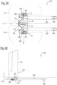
- Fig. 2A and 2B now show in a top view and a side view schematically an autonomously guided industrial truck 100, in which a base plate similar to that of Fig. 1A and which is accordingly also designated with the reference number 10.
- this base plate 10 in contrast to the one from Fig. 1A is provided with a contact surface 20.
- This contact surface 20 is located centrally and flush between two load arms 22a and 22b of the industrial truck 100, which each carry a load wheel 24a or 24b in the area of their ends remote from the base plate 10.
- a steered drive wheel 26 of the industrial truck 100 is accommodated, the hub of which extends above the base plate 10, so that the steered drive wheel 26 lies partly below and partly above the plane of the base plate 10.
- the essentially circular design of the central opening 14 also enables the drive wheel 26 to pivot about its vertical axis, which enables it to be steered.
- two support wheel arrangements 28a and 28b can be seen in the recesses 16a and 16b, which are also essentially circular and are mounted in the recesses 16a and 16b in such a way that they themselves, with their respective housing, form part of the outline of the base plate arrangement 102 thus formed in its front outer corner areas.
- the support wheel arrangements 28a and 28b are characterized in that their respective support wheels 30a and 30b can also be pivoted about a vertical axis to enable cornering, but the arrangements 28a and 28b have an extremely low construction height, which essentially corresponds to the thickness of the plate body 12, as can be seen in particular in Fig. 2B can be clearly seen.
- the support wheel arrangements 28a and 28b are aligned on their upper sides with the corresponding upper side of the plate body 12 and enable the installation of two scanner units 32a and 32b, which are also symmetrically opposite one another with respect to the longitudinal center axis, in the further recesses 18a and 18b.
- These scanner units 32a and 32b have, as in Fig. 2B can be seen, a scanning plane E with respective scanning areas S1 and S2, which runs horizontally above the base plate 10 and the load arms 22a and 22b.
- the scanner units 32a and 32b are protected on their sides by the walls of the plate body 12 against impacts occurring at this point, but are arranged in a suitable position in order to be able to cover the largest possible angular ranges of the scanning plane E, as can be seen from the Fig. 2A indicated areas S1 and S2. In variants of the embodiment shown here, however, scanner units with a different geometry could also be used, which could possibly make the provision of the further recesses 18a and 18b superfluous.
- an interface 34 is provided around the central opening 14 for connecting the base plate 10 to the vehicle frame 36 to form the vehicle body 104, in which further components of the industrial truck 100 can be accommodated.
- the specific shape of this interface 34 which is positioned such that it is arranged outside the central opening 14, but at a distance from the outline of the base plate 10 in the width direction B and is also designed to taper towards the front, allows the advantageous positioning of the scanner units 32a and 32b already discussed above, as well as the enlarged angular coverage of the scanning areas S1 and S2 also mentioned.
- the aim was to make the industrial truck 100 particularly narrow in the width direction B, for example with a width of no more than 800mm, while at the same time the scanner units 32a and 32b and the support wheel arrangements 28a and 28b are arranged as far out as possible in the width direction
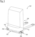
- the base plate 10' is made of Fig. 1B with its widening in the area of the recesses 16a' and 16b', so that a slightly modified base plate arrangement 102' and accordingly a modified vehicle body 104' results.
- the support wheel arrangements 28a and 28b are partially arranged outside the remaining vehicle geometry and their distance in the width direction B has been maximized.
- This measure can be taken, for example, in high-lift vehicles in order to increase the tipping stability of these vehicles in applications in which the widening of the corresponding industrial truck 100' is unproblematic at this point.
- the industrial truck 100' can be identical to the industrial truck 100 from the Fig. 2A and 2B formed and a more detailed description will be omitted here with reference to this figure.
Landscapes
- Engineering & Computer Science (AREA)
- Transportation (AREA)
- Structural Engineering (AREA)
- Civil Engineering (AREA)
- Life Sciences & Earth Sciences (AREA)
- Geology (AREA)
- Mechanical Engineering (AREA)
- Forklifts And Lifting Vehicles (AREA)
- Handcart (AREA)
Claims (15)
- Plaque de base (10 ; 10') pour un chariot de manutention (100 ; 100') guidé de manière autonome, présentant une direction longitudinale (L) et une direction de largeur (B), qui est prévue pour former un ensemble de plaque de base (102 ; 102') et pour délimiter localement vers le bas un corps de véhicule (104 ; 104') du chariot de manutention (100 ; 100'), comprenant :- un corps de plaque (12 ; 12') prévu pour définir au moins localement un contour de l'ensemble de plaque de base (102 ; 102'),la plaque de base (10 ; 10') présentant au moins un évidement (16a, 16b ; 16a', 16b') décalé dans la direction de la largeur (B) par rapport à un axe médian longitudinal (L), lequel est prévu pour recevoir un ensemble de roue d'appui (28a, 28b) du chariot de manutention (100 ; 100'),caractérisée en ce que la plaque de base présente une traversée (14 ; 14') centrale par rapport à la direction de la largeur (B), qui est prévue pour recevoir une roue motrice (26) du chariot de manutention (100 ; 100').
- Plaque de base (10 ; 10') selon la revendication 1,
caractérisée en ce qu'il est prévu deux évidements (16a, 16b ; 16a', 16b') qui sont disposés symétriquement par rapport à l'axe médian longitudinal (L). - Plaque de base (10 ; 10') selon l'une des revendications 1 et 2,
caractérisée en ce que ledit au moins un évidement (16a, 16b ; 16a', 16b') définit une partie du contour du corps de plaque (12 ; 12'), de préférence ledit au moins un évidement (16a, 16b ; 16a', 16b') définissant le contour de celui-ci dans une zone de coin, avant par rapport à la direction longitudinale (L) et extérieure par rapport à la direction de la largeur (B), du corps de plaque (12 ; 12'). - Plaque de base (10 ; 10') selon l'une des revendications précédentes,
caractérisée en ce qu'elle présente en outre au moins un autre évidement (18a, 18b ; 18a', 18b') prévu pour recevoir localement une unité de balayage (32a ; 32b). - Plaque de base (10 ; 10') selon la revendication 4,
caractérisée en ce que ledit au moins un autre évidement (18a, 18b ; 18a', 18b') se trouve entièrement à l'intérieur du contour de la plaque de base (10), et/ou en ce qu'il est prévu au moins deux autres évidements (18a, 18b ; 18a', 18b') qui sont disposés symétriquement par rapport à l'axe médian longitudinal (L). - Plaque de base (10 ; 10') selon l'une des revendications précédentes,
caractérisée en ce qu'elle présente, dans sa zone arrière par rapport à la direction longitudinale (L) et centrale par rapport à la direction de la largeur (B), une surface de support (20) prévue pour supporter un vérin de levage du chariot de manutention (100 ; 100'). - Plaque de base (10 ; 10') selon l'une des revendications précédentes,
caractérisée en ce qu'elle présente une extension maximale dans la direction de la largeur (B) d'environ 800 mm ou moins. - Plaque de base (10 ; 10') selon l'une des revendications précédentes,
caractérisée en ce que la traversée centrale (14 ; 14') et/ou au moins l'un des évidements (16a, 16b ; 16a', 16b') et/ou au moins l'un des autres évidements (18a, 18b ; 18a', 18b') est de forme sensiblement circulaire. - Ensemble de plaque de base (102 ; 102') pour un chariot de manutention guidé de manière autonome, comprenant :- une plaque de base (10 ; 10') selon l'une des revendications précédentes ;- au moins un ensemble de roue d'appui (28a, 28b) logé dans l'évidement ou dans l'un des évidements (18a, 18b ; 18a', 18b').
- Ensemble de plaque de base (102 ; 102') selon la revendication 9,
caractérisé en ce que ledit au moins un ensemble de roue d'appui (28a, 28b) et la plaque de base (10 ; 10') sont sensiblement à fleur l'un de l'autre sur leurs côtés supérieurs, ou la plaque de base (10 ; 10') s'étend vers le haut au-delà dudit au moins un ensemble de roue d'appui (28a, 28b). - Ensemble de plaque de base (102 ; 102') selon l'une des revendications 9 et 10,
caractérisé en ce qu'il comprend en outre au moins une unité de balayage (32a ; 32b) qui est disposée de telle sorte que son plan de balayage (E) se situe au-dessus de la plaque de base (10 ; 10'), ladite au moins une unité de balayage (32a, 32b) étant logée, le cas échéant localement, dans le ou l'un des autres évidements (18a, 18b ; 18a', 18b'). - Ensemble de plaque de base (102 ; 102') selon l'une des revendications 9 à 11,
caractérisé en ce que dans sa zone avant, deux bras de charge (22a, 22b) destinés à porter des roues de charge (24a, 24b) sont montés de manière fixe sur ledit ensemble, en particulier par soudage, les bras de charge (22a, 22b) s'étendant le cas échéant de part et d'autre de la surface de support (20) et étant par exemple disposés à fleur de celle-ci. - Corps de véhicule (104 ; 104') d'un chariot de manutention (100 ; 100') guidé de manière autonome,- comprenant un ensemble de plaque de base (102 ; 102') selon l'une des revendications 9 à 12, et- un châssis de véhicule (36) disposé au-dessus de la plaque de base (10 ; 10'),caractérisé par une interface (34) destinée à relier l'ensemble de plaque de base (102 ; 102') et le châssis de véhicule (36), qui est placée de manière à être disposée à l'extérieur de la traversée centrale (14 ; 14'), mais à une certaine distance du contour de la plaque de base (10 ; 10') dans la direction de la largeur (B).
- Corps de véhicule (104 ; 104') selon la revendication 13,
caractérisé en ce que, par rapport à l'axe médian longitudinal (L), ledit au moins un évidement (16a, 16b ; 16a', 16b') et, le cas échéant, ledit au moins un autre évidement (18a, 18b ; 18a', 18b') sont disposés à l'extérieur de l'interface (34) dans la direction de la largeur (B). - Chariot de manutention (100 ; 100') guidé de manière autonome, comprenant un corps de véhicule (104 ; 104') selon l'une des revendications 13 et 14.
Applications Claiming Priority (1)
| Application Number | Priority Date | Filing Date | Title |
|---|---|---|---|
| DE102021121217.0A DE102021121217A1 (de) | 2021-08-16 | 2021-08-16 | Grundplatte für ein autonom geführtes Flurförderzeug |
Publications (2)
| Publication Number | Publication Date |
|---|---|
| EP4137440A1 EP4137440A1 (fr) | 2023-02-22 |
| EP4137440B1 true EP4137440B1 (fr) | 2024-12-04 |
Family
ID=82786571
Family Applications (1)
| Application Number | Title | Priority Date | Filing Date |
|---|---|---|---|
| EP22188530.4A Active EP4137440B1 (fr) | 2021-08-16 | 2022-08-03 | Plaque de base pour un chariot autonome de manutention |
Country Status (4)
| Country | Link |
|---|---|
| US (1) | US12264054B2 (fr) |
| EP (1) | EP4137440B1 (fr) |
| CN (1) | CN115703625A (fr) |
| DE (1) | DE102021121217A1 (fr) |
Family Cites Families (19)
| Publication number | Priority date | Publication date | Assignee | Title |
|---|---|---|---|---|
| US2469812A (en) * | 1945-12-22 | 1949-05-10 | Breslav Jack | Attachment for industrial trucks |
| FR2716878B1 (fr) | 1994-03-04 | 1996-04-26 | Mic | Chariot de manutention avec roues stabilisatrices. |
| DE10022400C5 (de) | 2000-04-20 | 2008-11-06 | Jungheinrich Ag | Gabelhubwagen mit einem Fünfradfahrwerk |
| US7497505B2 (en) * | 2005-04-29 | 2009-03-03 | Crown Equipment Corporation | Suspended floorboard |
| DE102010012749A1 (de) | 2010-03-25 | 2011-09-29 | Kuka Laboratories Gmbh | Verfahren zum Betreiben eines autonomen Flurförderfahrzeugs |
| US8616603B2 (en) * | 2010-04-23 | 2013-12-31 | The Raymond Corporation | Operator ride enhancement system |
| US8517342B2 (en) * | 2011-04-25 | 2013-08-27 | Adrian Dunca | Door lifting and holding tool |
| FR3005932B1 (fr) | 2013-05-21 | 2015-05-01 | France Reducteurs | Ensemble electromecanique pour engin roulant, ainsi qu'un engin roulant equipe d'un tel ensemble electromecanique |
| DE102015101051A1 (de) * | 2015-01-26 | 2016-07-28 | Jungheinrich Aktiengesellschaft | Flurförderzeug mit einem auswechselbaren Batterieblock |
| DE102015102583A1 (de) * | 2015-02-24 | 2016-08-25 | Jungheinrich Aktiengesellschaft | Flurförderzeug mit einem Fahrerstandplatz |
| DE102015102584A1 (de) * | 2015-02-24 | 2016-08-25 | Jungheinrich Aktiengesellschaft | Flurförderzeug mit einem Fahrerstandplatz |
| CN206606990U (zh) * | 2017-03-10 | 2017-11-03 | 诺力机械股份有限公司 | 一种小转弯半径工业车辆 |
| EP3517483B1 (fr) * | 2018-01-24 | 2025-12-17 | Jungheinrich Aktiengesellschaft | Chariot élévateur à mât déplaçable pourvu de contrepoids |
| DE102018101539A1 (de) * | 2018-01-24 | 2019-07-25 | Jungheinrich Aktiengesellschaft | Grundrahmen für einen Schubmaststapler |
| DE202018104885U1 (de) | 2018-08-24 | 2019-11-26 | Blickle Räder + Rollen GmbH & Co. KG | Transportfahrzeug |
| CN108946586A (zh) * | 2018-09-14 | 2018-12-07 | 浙江斐尔德智能设备有限公司 | 多功能型自动导引运输车 |
| DE202019103019U1 (de) | 2019-05-28 | 2019-10-08 | August Schneider Lippstädter Schausteller Betriebe UG | Hinterradanordnung für ein Autoscooter-Fahrzeug |
| DE102020006337A1 (de) * | 2019-10-09 | 2021-04-15 | Metralabs Gmbh Neue Technologien Und Systeme | Autonomes Flurförderzeug |
| CN111717844A (zh) * | 2020-06-09 | 2020-09-29 | 安徽意欧斯物流机器人有限公司 | 一种工业安全型激光slam导航托盘堆垛式agv |
-
2021
- 2021-08-16 DE DE102021121217.0A patent/DE102021121217A1/de active Pending
-
2022
- 2022-08-03 EP EP22188530.4A patent/EP4137440B1/fr active Active
- 2022-08-10 CN CN202210958849.4A patent/CN115703625A/zh active Pending
- 2022-08-12 US US17/819,372 patent/US12264054B2/en active Active
Also Published As
| Publication number | Publication date |
|---|---|
| US12264054B2 (en) | 2025-04-01 |
| CN115703625A (zh) | 2023-02-17 |
| US20230050260A1 (en) | 2023-02-16 |
| EP4137440A1 (fr) | 2023-02-22 |
| DE102021121217A1 (de) | 2023-02-16 |
Similar Documents
| Publication | Publication Date | Title |
|---|---|---|
| WO2012136664A1 (fr) | Appareil élévateur à portique à entraînements électriques | |
| DE202018106492U1 (de) | Fahrzeug zum Transportieren eines langen Transportguts | |
| EP3296249B1 (fr) | Machine de travail articulée | |
| EP1932799B1 (fr) | Chariot de manutention | |
| EP4137442B1 (fr) | Chariot de manutention à guidage autonome doté d'une paire d'unités de balayeurs | |
| AT518649B1 (de) | Selbstfahrendes Flurfördergerät | |
| EP4137440A1 (fr) | Plaque de base pour un chariot autonome de manutention | |
| DE19700272B4 (de) | Flurförderzeug, insbesondere deichselgeführtes Flurförderzeug | |
| CH673988A5 (fr) | ||
| DE102005014907A1 (de) | Niederhub-Flurförderzeug | |
| DE19822809C2 (de) | Knickrahmengelenktes Ladefahrzeug | |
| DE19505456C2 (de) | Antriebsteil für ein Flurförderzeug | |
| EP0530742A2 (fr) | Chariot de manutention à fourches pour palettes | |
| EP4541696B1 (fr) | Véhicule de construction | |
| EP4137439B1 (fr) | Chariot de manutention à guidage autonome à trois niveaux de structure | |
| DE202009000041U1 (de) | Schwerlastgabelstapler mit einem Fahrgestell | |
| EP3390149B1 (fr) | Véhicule de transport pour conteneurs | |
| EP4046958B1 (fr) | Chariot de manutention pourvu de dispositifs de détection sur les dents de fourche | |
| DE102023204875B4 (de) | Selbstfahrendes Zweirichtungsfahrzeug | |
| DE19541677A1 (de) | Kommissionierhubwagen | |
| EP0827848A2 (fr) | Chassis pour véhicule à moteur ou remorques | |
| DE1556713C (de) | Dreiradstapler mit einem Hubmast | |
| DE102022115845A1 (de) | Flurförderzeug | |
| DE102015122860B4 (de) | Flurförderzeug zur Mitnahme an einem Lastkraftwagen | |
| EP2177470B1 (fr) | Chariot de manutention destiné au transport de palettes spéciales |
Legal Events
| Date | Code | Title | Description |
|---|---|---|---|
| PUAI | Public reference made under article 153(3) epc to a published international application that has entered the european phase |
Free format text: ORIGINAL CODE: 0009012 |
|
| STAA | Information on the status of an ep patent application or granted ep patent |
Free format text: STATUS: THE APPLICATION HAS BEEN PUBLISHED |
|
| AK | Designated contracting states |
Kind code of ref document: A1 Designated state(s): AL AT BE BG CH CY CZ DE DK EE ES FI FR GB GR HR HU IE IS IT LI LT LU LV MC MK MT NL NO PL PT RO RS SE SI SK SM TR |
|
| STAA | Information on the status of an ep patent application or granted ep patent |
Free format text: STATUS: REQUEST FOR EXAMINATION WAS MADE |
|
| 17P | Request for examination filed |
Effective date: 20230605 |
|
| RBV | Designated contracting states (corrected) |
Designated state(s): AL AT BE BG CH CY CZ DE DK EE ES FI FR GB GR HR HU IE IS IT LI LT LU LV MC MK MT NL NO PL PT RO RS SE SI SK SM TR |
|
| P01 | Opt-out of the competence of the unified patent court (upc) registered |
Effective date: 20230628 |
|
| GRAP | Despatch of communication of intention to grant a patent |
Free format text: ORIGINAL CODE: EPIDOSNIGR1 |
|
| STAA | Information on the status of an ep patent application or granted ep patent |
Free format text: STATUS: GRANT OF PATENT IS INTENDED |
|
| INTG | Intention to grant announced |
Effective date: 20240701 |
|
| GRAS | Grant fee paid |
Free format text: ORIGINAL CODE: EPIDOSNIGR3 |
|
| GRAA | (expected) grant |
Free format text: ORIGINAL CODE: 0009210 |
|
| STAA | Information on the status of an ep patent application or granted ep patent |
Free format text: STATUS: THE PATENT HAS BEEN GRANTED |
|
| AK | Designated contracting states |
Kind code of ref document: B1 Designated state(s): AL AT BE BG CH CY CZ DE DK EE ES FI FR GB GR HR HU IE IS IT LI LT LU LV MC MK MT NL NO PL PT RO RS SE SI SK SM TR |
|
| REG | Reference to a national code |
Ref country code: CH Ref legal event code: EP |
|
| REG | Reference to a national code |
Ref country code: DE Ref legal event code: R096 Ref document number: 502022002288 Country of ref document: DE |
|
| REG | Reference to a national code |
Ref country code: IE Ref legal event code: FG4D Free format text: LANGUAGE OF EP DOCUMENT: GERMAN |
|
| REG | Reference to a national code |
Ref country code: LT Ref legal event code: MG9D |
|
| REG | Reference to a national code |
Ref country code: NL Ref legal event code: MP Effective date: 20241204 |
|
| PG25 | Lapsed in a contracting state [announced via postgrant information from national office to epo] |
Ref country code: HR Free format text: LAPSE BECAUSE OF FAILURE TO SUBMIT A TRANSLATION OF THE DESCRIPTION OR TO PAY THE FEE WITHIN THE PRESCRIBED TIME-LIMIT Effective date: 20241204 |
|
| PG25 | Lapsed in a contracting state [announced via postgrant information from national office to epo] |
Ref country code: FI Free format text: LAPSE BECAUSE OF FAILURE TO SUBMIT A TRANSLATION OF THE DESCRIPTION OR TO PAY THE FEE WITHIN THE PRESCRIBED TIME-LIMIT Effective date: 20241204 |
|
| PG25 | Lapsed in a contracting state [announced via postgrant information from national office to epo] |
Ref country code: BG Free format text: LAPSE BECAUSE OF FAILURE TO SUBMIT A TRANSLATION OF THE DESCRIPTION OR TO PAY THE FEE WITHIN THE PRESCRIBED TIME-LIMIT Effective date: 20241204 |
|
| PG25 | Lapsed in a contracting state [announced via postgrant information from national office to epo] |
Ref country code: ES Free format text: LAPSE BECAUSE OF FAILURE TO SUBMIT A TRANSLATION OF THE DESCRIPTION OR TO PAY THE FEE WITHIN THE PRESCRIBED TIME-LIMIT Effective date: 20241204 |
|
| PG25 | Lapsed in a contracting state [announced via postgrant information from national office to epo] |
Ref country code: NO Free format text: LAPSE BECAUSE OF FAILURE TO SUBMIT A TRANSLATION OF THE DESCRIPTION OR TO PAY THE FEE WITHIN THE PRESCRIBED TIME-LIMIT Effective date: 20250304 |
|
| PG25 | Lapsed in a contracting state [announced via postgrant information from national office to epo] |
Ref country code: GR Free format text: LAPSE BECAUSE OF FAILURE TO SUBMIT A TRANSLATION OF THE DESCRIPTION OR TO PAY THE FEE WITHIN THE PRESCRIBED TIME-LIMIT Effective date: 20250305 Ref country code: LV Free format text: LAPSE BECAUSE OF FAILURE TO SUBMIT A TRANSLATION OF THE DESCRIPTION OR TO PAY THE FEE WITHIN THE PRESCRIBED TIME-LIMIT Effective date: 20241204 |
|
| PG25 | Lapsed in a contracting state [announced via postgrant information from national office to epo] |
Ref country code: RS Free format text: LAPSE BECAUSE OF FAILURE TO SUBMIT A TRANSLATION OF THE DESCRIPTION OR TO PAY THE FEE WITHIN THE PRESCRIBED TIME-LIMIT Effective date: 20250304 |
|
| PG25 | Lapsed in a contracting state [announced via postgrant information from national office to epo] |
Ref country code: NL Free format text: LAPSE BECAUSE OF FAILURE TO SUBMIT A TRANSLATION OF THE DESCRIPTION OR TO PAY THE FEE WITHIN THE PRESCRIBED TIME-LIMIT Effective date: 20241204 |
|
| PG25 | Lapsed in a contracting state [announced via postgrant information from national office to epo] |
Ref country code: SM Free format text: LAPSE BECAUSE OF FAILURE TO SUBMIT A TRANSLATION OF THE DESCRIPTION OR TO PAY THE FEE WITHIN THE PRESCRIBED TIME-LIMIT Effective date: 20241204 |
|
| PG25 | Lapsed in a contracting state [announced via postgrant information from national office to epo] |
Ref country code: PL Free format text: LAPSE BECAUSE OF FAILURE TO SUBMIT A TRANSLATION OF THE DESCRIPTION OR TO PAY THE FEE WITHIN THE PRESCRIBED TIME-LIMIT Effective date: 20241204 |
|
| PG25 | Lapsed in a contracting state [announced via postgrant information from national office to epo] |
Ref country code: IS Free format text: LAPSE BECAUSE OF FAILURE TO SUBMIT A TRANSLATION OF THE DESCRIPTION OR TO PAY THE FEE WITHIN THE PRESCRIBED TIME-LIMIT Effective date: 20250404 |
|
| PG25 | Lapsed in a contracting state [announced via postgrant information from national office to epo] |
Ref country code: PT Free format text: LAPSE BECAUSE OF FAILURE TO SUBMIT A TRANSLATION OF THE DESCRIPTION OR TO PAY THE FEE WITHIN THE PRESCRIBED TIME-LIMIT Effective date: 20250404 |
|
| PG25 | Lapsed in a contracting state [announced via postgrant information from national office to epo] |
Ref country code: EE Free format text: LAPSE BECAUSE OF FAILURE TO SUBMIT A TRANSLATION OF THE DESCRIPTION OR TO PAY THE FEE WITHIN THE PRESCRIBED TIME-LIMIT Effective date: 20241204 |
|
| PG25 | Lapsed in a contracting state [announced via postgrant information from national office to epo] |
Ref country code: RO Free format text: LAPSE BECAUSE OF FAILURE TO SUBMIT A TRANSLATION OF THE DESCRIPTION OR TO PAY THE FEE WITHIN THE PRESCRIBED TIME-LIMIT Effective date: 20241204 |
|
| PG25 | Lapsed in a contracting state [announced via postgrant information from national office to epo] |
Ref country code: SK Free format text: LAPSE BECAUSE OF FAILURE TO SUBMIT A TRANSLATION OF THE DESCRIPTION OR TO PAY THE FEE WITHIN THE PRESCRIBED TIME-LIMIT Effective date: 20241204 |
|
| PG25 | Lapsed in a contracting state [announced via postgrant information from national office to epo] |
Ref country code: CZ Free format text: LAPSE BECAUSE OF FAILURE TO SUBMIT A TRANSLATION OF THE DESCRIPTION OR TO PAY THE FEE WITHIN THE PRESCRIBED TIME-LIMIT Effective date: 20241204 |
|
| PG25 | Lapsed in a contracting state [announced via postgrant information from national office to epo] |
Ref country code: IT Free format text: LAPSE BECAUSE OF FAILURE TO SUBMIT A TRANSLATION OF THE DESCRIPTION OR TO PAY THE FEE WITHIN THE PRESCRIBED TIME-LIMIT Effective date: 20241204 |
|
| REG | Reference to a national code |
Ref country code: DE Ref legal event code: R097 Ref document number: 502022002288 Country of ref document: DE |
|
| PG25 | Lapsed in a contracting state [announced via postgrant information from national office to epo] |
Ref country code: SE Free format text: LAPSE BECAUSE OF FAILURE TO SUBMIT A TRANSLATION OF THE DESCRIPTION OR TO PAY THE FEE WITHIN THE PRESCRIBED TIME-LIMIT Effective date: 20241204 |
|
| PG25 | Lapsed in a contracting state [announced via postgrant information from national office to epo] |
Ref country code: DK Free format text: LAPSE BECAUSE OF FAILURE TO SUBMIT A TRANSLATION OF THE DESCRIPTION OR TO PAY THE FEE WITHIN THE PRESCRIBED TIME-LIMIT Effective date: 20241204 |
|
| PGFP | Annual fee paid to national office [announced via postgrant information from national office to epo] |
Ref country code: DE Payment date: 20250819 Year of fee payment: 4 |
|
| PLBE | No opposition filed within time limit |
Free format text: ORIGINAL CODE: 0009261 |
|
| STAA | Information on the status of an ep patent application or granted ep patent |
Free format text: STATUS: NO OPPOSITION FILED WITHIN TIME LIMIT |
|
| REG | Reference to a national code |
Ref country code: CH Ref legal event code: L10 Free format text: ST27 STATUS EVENT CODE: U-0-0-L10-L00 (AS PROVIDED BY THE NATIONAL OFFICE) Effective date: 20251015 |
|
| PGFP | Annual fee paid to national office [announced via postgrant information from national office to epo] |
Ref country code: FR Payment date: 20250821 Year of fee payment: 4 Ref country code: AT Payment date: 20251020 Year of fee payment: 4 |
|
| 26N | No opposition filed |
Effective date: 20250905 |
|
| REG | Reference to a national code |
Ref country code: CH Ref legal event code: H13 Free format text: ST27 STATUS EVENT CODE: U-0-0-H10-H13 (AS PROVIDED BY THE NATIONAL OFFICE) Effective date: 20260324 |
|
| PG25 | Lapsed in a contracting state [announced via postgrant information from national office to epo] |
Ref country code: MC Free format text: LAPSE BECAUSE OF FAILURE TO SUBMIT A TRANSLATION OF THE DESCRIPTION OR TO PAY THE FEE WITHIN THE PRESCRIBED TIME-LIMIT Effective date: 20241204 |
|
| PG25 | Lapsed in a contracting state [announced via postgrant information from national office to epo] |
Ref country code: LU Free format text: LAPSE BECAUSE OF NON-PAYMENT OF DUE FEES Effective date: 20250803 |
|
| PG25 | Lapsed in a contracting state [announced via postgrant information from national office to epo] |
Ref country code: CH Free format text: LAPSE BECAUSE OF NON-PAYMENT OF DUE FEES Effective date: 20250831 |