EP4137427B1 - Device for separately arranging supports for vacuum insulated glazing, and method - Google Patents
Device for separately arranging supports for vacuum insulated glazing, and method Download PDFInfo
- Publication number
- EP4137427B1 EP4137427B1 EP21788449.3A EP21788449A EP4137427B1 EP 4137427 B1 EP4137427 B1 EP 4137427B1 EP 21788449 A EP21788449 A EP 21788449A EP 4137427 B1 EP4137427 B1 EP 4137427B1
- Authority
- EP
- European Patent Office
- Prior art keywords
- separation
- supports
- support
- vacuum insulated
- insulated glazing
- Prior art date
- Legal status (The legal status is an assumption and is not a legal conclusion. Google has not performed a legal analysis and makes no representation as to the accuracy of the status listed.)
- Active
Links
Images



Classifications
-
- E—FIXED CONSTRUCTIONS
- E06—DOORS, WINDOWS, SHUTTERS, OR ROLLER BLINDS IN GENERAL; LADDERS
- E06B—FIXED OR MOVABLE CLOSURES FOR OPENINGS IN BUILDINGS, VEHICLES, FENCES OR LIKE ENCLOSURES IN GENERAL, e.g. DOORS, WINDOWS, BLINDS, GATES
- E06B3/00—Window sashes, door leaves, or like elements for closing wall or like openings; Layout of fixed or moving closures, e.g. windows in wall or like openings; Features of rigidly-mounted outer frames relating to the mounting of wing frames
- E06B3/66—Units comprising two or more parallel glass or like panes permanently secured together
- E06B3/673—Assembling the units
- E06B3/67326—Assembling spacer elements with the panes
-
- B—PERFORMING OPERATIONS; TRANSPORTING
- B65—CONVEYING; PACKING; STORING; HANDLING THIN OR FILAMENTARY MATERIAL
- B65G—TRANSPORT OR STORAGE DEVICES, e.g. CONVEYORS FOR LOADING OR TIPPING, SHOP CONVEYOR SYSTEMS OR PNEUMATIC TUBE CONVEYORS
- B65G47/00—Article or material-handling devices associated with conveyors; Methods employing such devices
- B65G47/74—Feeding, transfer, or discharging devices of particular kinds or types
- B65G47/90—Devices for picking-up and depositing articles or materials
- B65G47/91—Devices for picking-up and depositing articles or materials incorporating pneumatic, e.g. suction, grippers
-
- B—PERFORMING OPERATIONS; TRANSPORTING
- B65—CONVEYING; PACKING; STORING; HANDLING THIN OR FILAMENTARY MATERIAL
- B65G—TRANSPORT OR STORAGE DEVICES, e.g. CONVEYORS FOR LOADING OR TIPPING, SHOP CONVEYOR SYSTEMS OR PNEUMATIC TUBE CONVEYORS
- B65G47/00—Article or material-handling devices associated with conveyors; Methods employing such devices
- B65G47/02—Devices for feeding articles or materials to conveyors
- B65G47/04—Devices for feeding articles or materials to conveyors for feeding articles
- B65G47/12—Devices for feeding articles or materials to conveyors for feeding articles from disorderly-arranged article piles or from loose assemblages of articles
- B65G47/14—Devices for feeding articles or materials to conveyors for feeding articles from disorderly-arranged article piles or from loose assemblages of articles arranging or orientating the articles by mechanical or pneumatic means during feeding
- B65G47/1407—Devices for feeding articles or materials to conveyors for feeding articles from disorderly-arranged article piles or from loose assemblages of articles arranging or orientating the articles by mechanical or pneumatic means during feeding the articles being fed from a container, e.g. a bowl
- B65G47/1414—Devices for feeding articles or materials to conveyors for feeding articles from disorderly-arranged article piles or from loose assemblages of articles arranging or orientating the articles by mechanical or pneumatic means during feeding the articles being fed from a container, e.g. a bowl by means of movement of at least the whole wall of the container
- B65G47/1421—Vibratory movement
-
- B—PERFORMING OPERATIONS; TRANSPORTING
- B23—MACHINE TOOLS; METAL-WORKING NOT OTHERWISE PROVIDED FOR
- B23P—METAL-WORKING NOT OTHERWISE PROVIDED FOR; COMBINED OPERATIONS; UNIVERSAL MACHINE TOOLS
- B23P19/00—Machines for simply fitting together or separating metal parts or objects, or metal and non-metal parts, whether or not involving some deformation; Tools or devices therefor so far as not provided for in other classes
- B23P19/001—Article feeders for assembling machines
-
- B—PERFORMING OPERATIONS; TRANSPORTING
- B65—CONVEYING; PACKING; STORING; HANDLING THIN OR FILAMENTARY MATERIAL
- B65G—TRANSPORT OR STORAGE DEVICES, e.g. CONVEYORS FOR LOADING OR TIPPING, SHOP CONVEYOR SYSTEMS OR PNEUMATIC TUBE CONVEYORS
- B65G47/00—Article or material-handling devices associated with conveyors; Methods employing such devices
- B65G47/74—Feeding, transfer, or discharging devices of particular kinds or types
- B65G47/88—Separating or stopping elements, e.g. fingers
-
- B—PERFORMING OPERATIONS; TRANSPORTING
- B65—CONVEYING; PACKING; STORING; HANDLING THIN OR FILAMENTARY MATERIAL
- B65G—TRANSPORT OR STORAGE DEVICES, e.g. CONVEYORS FOR LOADING OR TIPPING, SHOP CONVEYOR SYSTEMS OR PNEUMATIC TUBE CONVEYORS
- B65G47/00—Article or material-handling devices associated with conveyors; Methods employing such devices
- B65G47/74—Feeding, transfer, or discharging devices of particular kinds or types
- B65G47/90—Devices for picking-up and depositing articles or materials
- B65G47/91—Devices for picking-up and depositing articles or materials incorporating pneumatic, e.g. suction, grippers
- B65G47/918—Devices for picking-up and depositing articles or materials incorporating pneumatic, e.g. suction, grippers with at least two picking-up heads
-
- B—PERFORMING OPERATIONS; TRANSPORTING
- B65—CONVEYING; PACKING; STORING; HANDLING THIN OR FILAMENTARY MATERIAL
- B65G—TRANSPORT OR STORAGE DEVICES, e.g. CONVEYORS FOR LOADING OR TIPPING, SHOP CONVEYOR SYSTEMS OR PNEUMATIC TUBE CONVEYORS
- B65G49/00—Conveying systems characterised by their application for specified purposes not otherwise provided for
- B65G49/05—Conveying systems characterised by their application for specified purposes not otherwise provided for for fragile or damageable materials or articles
- B65G49/06—Conveying systems characterised by their application for specified purposes not otherwise provided for for fragile or damageable materials or articles for fragile sheets, e.g. glass
- B65G49/063—Transporting devices for sheet glass
- B65G49/064—Transporting devices for sheet glass in a horizontal position
-
- C—CHEMISTRY; METALLURGY
- C03—GLASS; MINERAL OR SLAG WOOL
- C03C—CHEMICAL COMPOSITION OF GLASSES, GLAZES OR VITREOUS ENAMELS; SURFACE TREATMENT OF GLASS; SURFACE TREATMENT OF FIBRES OR FILAMENTS MADE FROM GLASS, MINERALS OR SLAGS; JOINING GLASS TO GLASS OR OTHER MATERIALS
- C03C27/00—Joining pieces of glass to pieces of other inorganic material; Joining glass to glass other than by fusing
- C03C27/06—Joining glass to glass by processes other than fusing
-
- E—FIXED CONSTRUCTIONS
- E06—DOORS, WINDOWS, SHUTTERS, OR ROLLER BLINDS IN GENERAL; LADDERS
- E06B—FIXED OR MOVABLE CLOSURES FOR OPENINGS IN BUILDINGS, VEHICLES, FENCES OR LIKE ENCLOSURES IN GENERAL, e.g. DOORS, WINDOWS, BLINDS, GATES
- E06B3/00—Window sashes, door leaves, or like elements for closing wall or like openings; Layout of fixed or moving closures, e.g. windows in wall or like openings; Features of rigidly-mounted outer frames relating to the mounting of wing frames
- E06B3/66—Units comprising two or more parallel glass or like panes permanently secured together
- E06B3/6612—Evacuated glazing units
-
- E—FIXED CONSTRUCTIONS
- E06—DOORS, WINDOWS, SHUTTERS, OR ROLLER BLINDS IN GENERAL; LADDERS
- E06B—FIXED OR MOVABLE CLOSURES FOR OPENINGS IN BUILDINGS, VEHICLES, FENCES OR LIKE ENCLOSURES IN GENERAL, e.g. DOORS, WINDOWS, BLINDS, GATES
- E06B3/00—Window sashes, door leaves, or like elements for closing wall or like openings; Layout of fixed or moving closures, e.g. windows in wall or like openings; Features of rigidly-mounted outer frames relating to the mounting of wing frames
- E06B3/66—Units comprising two or more parallel glass or like panes permanently secured together
- E06B3/663—Elements for spacing panes
- E06B3/66304—Discrete spacing elements, e.g. for evacuated glazing units
-
- B—PERFORMING OPERATIONS; TRANSPORTING
- B65—CONVEYING; PACKING; STORING; HANDLING THIN OR FILAMENTARY MATERIAL
- B65G—TRANSPORT OR STORAGE DEVICES, e.g. CONVEYORS FOR LOADING OR TIPPING, SHOP CONVEYOR SYSTEMS OR PNEUMATIC TUBE CONVEYORS
- B65G2201/00—Indexing codes relating to handling devices, e.g. conveyors, characterised by the type of product or load being conveyed or handled
- B65G2201/04—Bulk
- B65G2201/042—Granular material
-
- Y—GENERAL TAGGING OF NEW TECHNOLOGICAL DEVELOPMENTS; GENERAL TAGGING OF CROSS-SECTIONAL TECHNOLOGIES SPANNING OVER SEVERAL SECTIONS OF THE IPC; TECHNICAL SUBJECTS COVERED BY FORMER USPC CROSS-REFERENCE ART COLLECTIONS [XRACs] AND DIGESTS
- Y02—TECHNOLOGIES OR APPLICATIONS FOR MITIGATION OR ADAPTATION AGAINST CLIMATE CHANGE
- Y02A—TECHNOLOGIES FOR ADAPTATION TO CLIMATE CHANGE
- Y02A30/00—Adapting or protecting infrastructure or their operation
- Y02A30/24—Structural elements or technologies for improving thermal insulation
- Y02A30/249—Glazing, e.g. vacuum glazing
-
- Y—GENERAL TAGGING OF NEW TECHNOLOGICAL DEVELOPMENTS; GENERAL TAGGING OF CROSS-SECTIONAL TECHNOLOGIES SPANNING OVER SEVERAL SECTIONS OF THE IPC; TECHNICAL SUBJECTS COVERED BY FORMER USPC CROSS-REFERENCE ART COLLECTIONS [XRACs] AND DIGESTS
- Y02—TECHNOLOGIES OR APPLICATIONS FOR MITIGATION OR ADAPTATION AGAINST CLIMATE CHANGE
- Y02B—CLIMATE CHANGE MITIGATION TECHNOLOGIES RELATED TO BUILDINGS, e.g. HOUSING, HOUSE APPLIANCES OR RELATED END-USER APPLICATIONS
- Y02B80/00—Architectural or constructional elements improving the thermal performance of buildings
- Y02B80/22—Glazing, e.g. vaccum glazing
Definitions
- the present invention relates to the field of manufacturing equipment of vacuum insulated glazing, in particular to a device and method for separating granular supports.
- the separation method currently in use is to arrange the granules in sequence by a spiral vibrating disk, send the granules into the feed tube one by one through intermittent flow of compressed air and then arrange the granules onto the surface of the glazing.
- the force of the air flow may affect the accuracy of the separation, causing unwanted granules on the surface of the glazing. Therefore, it is required to inspect the number of the supports on the surface of the glazing, remove the unwanted supports and perform an additional arrangement of supports, which increases the inspection cost, lengthens the production cycle and reduces the production efficiency.
- CN106045286A discloses a vacuum glass support separation device.
- An object of the present invention is to provide a device for separating supports for vacuum insulated glazing, which is novel and unique in structure and convenient to use and is capable of obtaining individual supports.
- the specific technical solution is as follows:
- the present invention provides a device for separating supports for vacuum insulated glazing, including a base, a vibrator, a separation chamber assembly, a separation actuator, a feed tube, and a drive device.
- the drive device is provided at a side of the base and connected to the separation actuator, and the separation chamber assembly, the separation actuator, and the feed tube are sequentially provided at another side of the base from top to bottom.
- the drive device is adapted to push the separation actuator to make reciprocating movements.
- the vibrator is provided on the separation chamber assembly.
- the separation chamber assembly is provided with a feed inlet, an accommodation cavity, and a dispensing outlet, the feed inlet is communicated with the accommodation cavity, the dispensing outlet is communicated with the feed tube, and the separation chamber assembly is inclinedly arranged with respect to a horizontal plane.
- the separation actuator passes through the separation chamber assembly, and is provided at a lower portion of the accommodation cavity in a reciprocatingly movable manner.
- An upper edge of the separation actuator at a side close to the dispensing outlet is provided with a recess capable of accommodating one support.
- the accommodation cavity is communicated with the dispensing outlet via the recess of the separation actuator.
- the device for separating supports for vacuum insulated glazing further includes a hopper and a limit baffle.
- the separation chamber assembly is disposed on a bottom plate inclined with respect to the horizontal plane through the limit baffle.
- the separation chamber assembly includes an upper separation chamber plate and a lower separation chamber plate disposed in parallel.
- the upper separation chamber plate is provided with the feed inlet.
- the lower separation chamber plate is provided with the dispensing outlet.
- the accommodation cavity is a convex accommodation cavity disposed on an end surface of the upper separation chamber plate away from the hopper and/or an end surface of the lower separation chamber plate close to the hopper.
- a convex portion at an upper end of the convex accommodation cavity is provided with the feed inlet communicated with the hopper, the lower portion of the convex accommodation cavity is provided with the dispensing outlet communicated with the recess of the separation actuator, and the separation actuator makes the reciprocating movements along the lower portion of the convex accommodation cavity.
- a thickness of the convex accommodation cavity is d
- a thickness of the support is d1 and a maximum distance between any two points on a cross section of the support is d2, then d1 ⁇ d ⁇ d2, and d ⁇ 2d1.
- a height of the recess of the separation actuator is h
- a width of the recess of the separation actuator is w
- a maximum distance between any two points on a cross section of the support is d2
- d2 ⁇ h, d2 ⁇ w, a difference between d2 and h is in a range of 0.01 mm-0.5 mm
- a difference between d2 and w is in a range of 0.01 mm-0.5 mm.
- the difference between d2 and h is in the range of 0.1 mm-0.2 mm, and the difference between d2 and w is in the range of 0.1 mm-0.2 mm.
- the feed tube is a transparent tube, and a wall of the feed tube is provided with a sensor.
- an inner diameter of the feed tube is r and a maximum distance between any two points on a cross section of the support is d2, then r>d2, and a difference between r and d2 is in a range of 0.01 mm-0.5 mm.
- r and d2 are in the range of 0. 1 mm-0.2 mm.
- a lower portion of the feed tube is further provided with a transition joint, an inner cavity of the transition joint is provided with an inverted conical transition section, and the inner cavity of the transition joint has a trumpet-shaped bottom.
- the senor is an optical fiber sensor.
- the separation actuator is plate-shaped or rod-shaped.
- a thickness of the support is d1
- a thickness of the separation actuator is d3
- a width of the recess of the separation actuator is w
- a width of the separation actuator is w1
- an included angle between the separation chamber assembly and the horizontal plane is 5° to 75°.
- the included angle between the separation chamber assembly and the horizontal plane is 25° to 75°.
- the separation chamber assembly is made of a wear-resistant and nonmagnetic material
- the upper separation chamber plate is provided with an observation window for observing the state of the support in the accommodation cavity and the transportation of the support by the separation actuator.
- the present invention provides a system for arranging supports for vacuum insulated glazing, including a transmission section, a control system and a plurality of the devices for separating supports for vacuum insulated glazing according to any of the above.
- the transmission section includes a frame and a transmission roller table disposed on the frame, and the frame is provided with a support beam.
- the separation devices are linearly arranged on the support beam at intervals and perform a support separation operation at the same time, so that the arrangement of the supports in one row in the vacuum insulated glazing is completed by one or more operations.
- the plurality of devices for separating supports for vacuum insulated glazing according to any of the above are arranged on the support beam in an array and perform the support separation operation at the same time, so that the arrangement of the supports in one area is completed by one or more operations.
- the system for arranging supports for vacuum insulated glazing further includes a movement control mechanism.
- the movement control mechanism is disposed on the frame and used to control the support beam to move along a glazing conveying direction and/or a direction perpendicular to the glazing conveying direction.
- the present invention provides a method for separating supports for vacuum insulated glazing using the device for separating supports for vacuum insulated glazing, including the following steps:
- the present invention provides a method for arranging supports for vacuum insulated glazing using the system for arranging supports for vacuum insulated glazing as described above, including the following steps:
- the device for separating supports for vacuum insulated glazing according to the present invention is arranging supports, one reciprocating movement of the separation actuator can only transport one support, thereby eliminating the case in which multiple supports are arranged in one operation.
- 1 base; 2, cylinder mounting frame; 3, cylinder; 4, separation plate fixing block; 5, separation plate; 51, separation recess; 6, hopper; 7, separation chamber assembly; 71, upper separation chamber plate; 72, lower separation chamber plate; 8, feed tube; 9, optical fiber sensor; 10, feed tube clamp; 11, vibrator; 12, support; 13, limit baffle; 131, upper baffle; 132, lower baffle; and 14, bottom plate.
- S1 transmission section; S11, transmission frame; S12, transmission power; S13, transmission roller table; S2, glazing; S3, transverse movement bracket; S4, transverse movement control mechanism; S5, support beam; S6, separation device; S7, feed tube lifting mechanism; S71, blanking assembly; S711, feed tube; S712, guide sleeve; S713, compression spring; S714, transition joint; S72, guide assembly; S73, lifting power; and S74, fixing plate.
- space-related terms such as “up”, “down”, “left”, and “right”, may be used herein for describing a relationship between one element or feature and another element or feature as shown in the figures. It should be understood that, the space terms are intended to encompass different orientations of the device in use or operation other than the orientations described in the figures.
- the exemplary term “below” may include both above and below.
- the device may be oriented in other ways (rotated by 90 degrees or in other orientations), and the spatially relative description used herein can be interpreted accordingly.
- a support 12 may be in a round pie shape or in a pie shape with a polygonal cross section (as shown in FIG. 12 and FIG. 13 ).
- a round pie-shaped object having a diameter of 0.5 mm-0.9 mm and a thickness of 0.2 mm-0.4 mm is taken as an example for description.
- a device for separating supports for vacuum insulated glazing in this embodiment includes a base 1, a hopper 6, a vibrator 11, a separation chamber assembly 7, a limit baffle 13, a separation plate 5, a feed tube 8 and a cylinder 3.
- the cylinder 3 is provided at a side of the base 1, and the hopper 6, the separation chamber assembly 7, the separation plate 5 and the feed tube 8 are sequentially provided at another side of the base 1 from top to bottom.
- the vibrator 11 is provided on the separation chamber assembly 7. Vibrations generated by the vibrator 11 drive the separation chamber assembly 7 to vibrate.
- the separation chamber assembly 7 is made of a wear-resistant and nonmagnetic material. The vibrations increase the fluidity of the granular supports, thereby ensuring the supports 12 to be arranged loosely.
- the separation chamber assembly 7 includes an upper separation chamber plate 71 and a lower separation chamber plate 72 disposed in parallel.
- the upper separation chamber plate 71 is provided with an observation window for observing the state of the support in the convex accommodation cavity and the transportation of the support by the separation plate 5.
- the separation chamber assembly 7 is disposed on a bottom plate 14 inclined with respect to the horizontal plane.
- the limit baffle 13 is disposed outside the separation chamber assembly 7. A clearance is left between the limit baffle 13 and the separation chamber assembly 7, such that the separation chamber assembly 7 can vibrate.
- the upper separation chamber plate 71 is provided with a feed inlet communicated with the hopper 6, and the lower separation chamber plate 72 is provided with a dispensing outlet communicated with the feed tube 8.
- the convex accommodation cavity is disposed on an end surface of the upper separation chamber plate 71 away from the hopper 6 and/or an end surface of the lower separation chamber plate 72 close to the hopper 6.
- the separation plate 5 is movably provided at a lower portion of the convex accommodation cavity and connected to the cylinder 3, and is driven by the cylinder 3 to make reciprocating movements along the lower portion of the accommodation cavity.
- a convex portion at an upper end of the convex accommodation cavity is communicated with the hopper 6 via the feed inlet.
- An upper edge of the separation plate 5 at a side close to the convex portion at the upper end of the convex accommodation cavity is provided with a separation recess 51.
- the reciprocating movement direction is the width direction
- the direction perpendicular to the reciprocating movement is the height direction
- the direction perpendicular to the plane where the separation plate 5 is located is the thickness direction.
- the separation plate 5 is in a clearance fit with the lower portion of the convex accommodation cavity.
- the clearance should be less than a thickness d1 of the support 12, to prevent the support 12 from running out of the convex portion at the upper end of the convex accommodation cavity via the clearance during the reciprocating movements of the separation plate 5.
- a thickness d of the convex accommodation cavity is greater than a thickness d1 of the support 12, and the thickness d of the convex accommodation cavity is less than a cross-sectional diameter d2 of the support 12, so that the supports 12 can only be arranged with its bottom surface falling on the lower separation chamber plate 72 under the vibrations of the separation chamber assembly inclinedly arranged with respect to the horizontal plane.
- the thickness d of the convex accommodation cavity is less than twice the thickness d1 of the support 12, which prevents the supports in the convex accommodation cavity from being arranged in double layers.
- a width w of the separation recess 51 is less than a width w1 of the separation plate 5.
- a thickness d3 of the separation plate 5 is greater than the thickness d1 of the support 12.
- a height h of the separation recess 51 is greater than the cross-sectional diameter d2 of the support 12 by 0.1 mm-0.2 mm, and the width w of the separation recess 51 is greater than the cross-sectional diameter d2 of the support 12 by 0.1 mm-0.2 mm, so that the support 12 can smoothly enter the separation recess 51 and the separation recess 51 can only accommodate one support.
- a drive mechanism is mounted on the base 1.
- the drive mechanism may be the cylinder 3.
- a cylinder block of the cylinder 3 is fixed to the base 1 via a cylinder mounting frame 2.
- a piston rod is fixedly connected to the separation plate 5 via a separation plate fixing block 4.
- An upper baffle 131 and a lower baffle 132 are disposed outside the separation chamber assembly 7.
- the upper separation chamber plate 71, the lower separation chamber plate 72 and the bottom plate 14 are assembled together via the L-shaped upper baffle 131 and the lower baffle 132.
- the bottom plate 14 is fixed to the base 1 inclinedly with respect to the horizontal plane.
- the distance of the reciprocating movement of the separation plate 5 is such that the support 12 is conveyed into the dispensing outlet at a connecting channel between the lower separation chamber plate 72 and the feed tube 8 after the separation recess 51 obtains the support 12 from the convex accommodation cavity.
- one or two sides of the convex portion at the upper end of the convex accommodation cavity may be provided with a slope or slopes communicated with the separation plate 5 via a channel at the bottom of the slope, which further reduces the advancing resistance of the separation plate carrying the support 12.
- the separation actuator is not limited to the plate-shaped separation actuator in the figure, and may also be a rod-shaped separation actuator.
- the separation actuator is a round rod, the end portion should be treated, for example perforated, to ensure that the recess is on the top surface during mounting.
- a lower edge of the separation actuator at a side away from the convex portion at the upper end of the convex accommodation cavity may also be provided with the separation recess 51 capable of accommodating one support. After the recess at the side of the separation plate 5 close to the convex portion at the upper end of the convex accommodation cavity is worn, the separation plate may be turned over, which prolongs the service life of the separation actuator.
- the feed tube 8 is a transparent tube made of glass or other transparent materials, and a sensor is provided on a wall of the feed tube 8 to detect whether a support falls.
- the sensor is fixed to the feed tube 8 via a feed tube clamp 10.
- the sensor is an optical fiber sensor 9, which has higher detection sensitivity.
- An included angle between the bottom plate 14 and the horizontal plane is 25° to 75°.
- An inner diameter of the feed tube 8 is greater than a diameter of the support 12 by 0.1 mm-0.2 mm, so that the supports 12 can pass through smoothly.
- the separation plate 5 may be pushed to make the reciprocating movements by the cylinder 3 or an electric cylinder; or the separation plate 5 may be pushed to make the reciprocating movements by a crank-connecting rod mechanism driven by a stepping motor.
- the demagnetized supports 12 are added via the hopper 6 at the top.
- the vibrator is started such that the supports 12 are loosely arranged in one layer in a sequence of entering the convex accommodation cavity.
- the cylinder 3 is started to push the separation plate 5. Under the action of the vibrator, the supports 12 fall into the separation recess 51 of the separation plate 5 at an end close to the convex portion at the upper end of the convex accommodation cavity.
- the separation plate 5 moves rightward to convey the support 12 in the separation recess 51 to the dispensing outlet.
- the cylinder 3 stops driving, and the support 12 passes through the bottom plate 14 via the dispensing outlet, enters the feed tube 8, and is discharged via the bottom end of the feed tube 8.
- the cylinder 3 acts in the reverse direction, and the separation plate 5 retracts, so that the separation recess 51 enters the convex portion at the upper end of the convex accommodation cavity.
- a system for arranging supports for vacuum insulated glazing in this embodiment includes a transmission section S1, a control system (not shown) and a separation devices S6.
- the transmission section S1 includes a transmission frame S1 1 and a transmission roller table S13 on the transmission frame S11.
- Transmission power S12 provides a driving force for the transmission roller table S13.
- the motor drives the transmission roller table S13 via a belt or a sprocket after a reducer. When a servo motor is used, the speed reducer may also be omitted.
- the control system is a PLC control system located in an electrical control cabinet of a vacuum insulated glazing production line.
- the PLC control system is electrically connected to a transmission power S12 device of the transmission roller table S13 and the separation device S6, and controls the rotation of the transmission roller table S13 and the separation and arrangement of the support 12.
- Glazing S2 is placed on the transmission roller table S13 and is capable of moving back and forth along the transmission roller table S13.
- the top surface of the transmission frame S11 and the left and right sides of the transmission roller table S13 are respectively provided with a transverse movement bracket S3, and a support beam S5 is disposed over the transverse movement bracket S3.
- the transverse movement bracket S3 is disposed horizontally. In the figure, the transverse movement bracket S3 is disposed in a direction perpendicular to the movement direction of the glazing S2, and may also be disposed inclinedly at an angle of 45 degrees, 30 degrees, etc. with the movement direction of the glazing S2.
- the separation device S6 is disposed on the support beam S5 via the base 1. There may be one or more separation devices S6. In this embodiment, there are six separation devices S6.
- the separation devices S6 are linearly arranged on the support beam S5 at intervals. In other embodiments of the present invention, the separation devices may be arranged on the support beam S5 at intervals in an array.
- the system is further provided with a feed tube lifting mechanism S7.
- a blanking assembly S71 descends, the separation devices S6 separate the supports 12, the support 12 falls off from the feed tube 8, and the optical fiber sensor 9 detects the passage of the support.
- the support stops on the surface of the glazing S2 via the blanking assembly S71.
- the PLC control system controls the corresponding separation device S6 to execute the separation operation again until the optical fiber sensor 9 detects the passage of the support.
- the blanking assembly S71 ascends, which prevents the support 12 from colliding with the lower end of the blanking assembly S71 when the glazing S2 moves forward.
- the movement control mechanism includes a transverse movement control mechanism S4 and a longitudinal movement control mechanism.
- the longitudinal movement control mechanism controls the longitudinal step-by-step movement of the support beam S5.
- the longitudinal movement control mechanism is electrically connected to the PLC control system.
- the blanking assembly S71 includes a feed tube S711, a guide sleeve S712, a compression spring S713 and a transition joint S714.
- the feed tube 8 of the separation device S6 is inserted into a material through hole at the center of the feed tube S711, and a clearance is provided between an outer wall of the feed tube 8 and an inner wall of the material through hole.
- An upper end of the feed tube S711 is provided with a stepped surface.
- the stepped surface has a larger outer diameter at the upper end and a smaller outer diameter at the lower end.
- the guide sleeve S712 is sleeved on a smaller end of the feed tube S711, and the compression spring S713 and the transition joint S714 are sequentially arranged below the guide sleeve.
- the transition joint S714 is fixed to the lower end of the feed tube S711 by a thread, a snap-in hole or a pin.
- the guide sleeve S712 and the transition joint S714 clamp the compression spring S713 in a compressed state.
- the guide sleeve S712 is fixed to a fixing plate S74. When the fixing plate S74 descends, the compression spring S713 pushes the transition joint S714, so that a lower end surface of the transition joint S714 is in close contact with the surface of the glazing S2.
- the guide sleeve S712 drives the feed tube S711 to ascend via the stepped surface.
- the support beam S5 is further provided with a feed tube lifting mechanism S7.
- the feed tube lifting mechanism S7 includes a guide assembly S72, lifting power S73 and a fixing plate S74.
- the guide assembly S72 is composed of a guide sleeve and a guide rod.
- the lifting power S73 is provided by an electric cylinder or a cylinder.
- the lifting power S73 drives the fixing plate S74 to move up and down.
- an inner cavity of the transition joint S714 is provided with an inverted conical transition section, and the inner cavity of the transition joint S714 has a trumpet-shaped bottom, so that the supports 12 can be accurately located on the glazing S2 after being sorted via the transition section, which prevents the support from bouncing off its proper position or bouncing off the glazing S2.
Landscapes
- Engineering & Computer Science (AREA)
- Mechanical Engineering (AREA)
- Chemical & Material Sciences (AREA)
- Structural Engineering (AREA)
- Civil Engineering (AREA)
- General Chemical & Material Sciences (AREA)
- Chemical Kinetics & Catalysis (AREA)
- Geochemistry & Mineralogy (AREA)
- Materials Engineering (AREA)
- Organic Chemistry (AREA)
- Life Sciences & Earth Sciences (AREA)
- Ceramic Engineering (AREA)
- Feeding Of Articles To Conveyors (AREA)
- Joining Of Glass To Other Materials (AREA)
- Securing Of Glass Panes Or The Like (AREA)
Description
- The present invention relates to the field of manufacturing equipment of vacuum insulated glazing, in particular to a device and method for separating granular supports.
- In the process of making vacuum insulated glazing, since there is a vacuum between the two panes, it is necessary to arrange supports in the vacuum layer to withstand the external atmospheric pressure. The particle size of the supports in the middle is in a range of 0.1 mm-0.5 mm. The separation method currently in use is to arrange the granules in sequence by a spiral vibrating disk, send the granules into the feed tube one by one through intermittent flow of compressed air and then arrange the granules onto the surface of the glazing. In the separation process, the force of the air flow may affect the accuracy of the separation, causing unwanted granules on the surface of the glazing. Therefore, it is required to inspect the number of the supports on the surface of the glazing, remove the unwanted supports and perform an additional arrangement of supports, which increases the inspection cost, lengthens the production cycle and reduces the production efficiency.
-
CN106045286A discloses a vacuum glass support separation device. - An object of the present invention is to provide a device for separating supports for vacuum insulated glazing, which is novel and unique in structure and convenient to use and is capable of obtaining individual supports. The specific technical solution is as follows:
The present invention provides a device for separating supports for vacuum insulated glazing, including a base, a vibrator, a separation chamber assembly, a separation actuator, a feed tube, and a drive device. The drive device is provided at a side of the base and connected to the separation actuator, and the separation chamber assembly, the separation actuator, and the feed tube are sequentially provided at another side of the base from top to bottom. The drive device is adapted to push the separation actuator to make reciprocating movements. - The vibrator is provided on the separation chamber assembly. The separation chamber assembly is provided with a feed inlet, an accommodation cavity, and a dispensing outlet, the feed inlet is communicated with the accommodation cavity, the dispensing outlet is communicated with the feed tube, and the separation chamber assembly is inclinedly arranged with respect to a horizontal plane. The separation actuator passes through the separation chamber assembly, and is provided at a lower portion of the accommodation cavity in a reciprocatingly movable manner. An upper edge of the separation actuator at a side close to the dispensing outlet is provided with a recess capable of accommodating one support. During reciprocating movements of the separation actuator, the accommodation cavity is communicated with the dispensing outlet via the recess of the separation actuator.
- Further, the device for separating supports for vacuum insulated glazing further includes a hopper and a limit baffle. The separation chamber assembly is disposed on a bottom plate inclined with respect to the horizontal plane through the limit baffle. The separation chamber assembly includes an upper separation chamber plate and a lower separation chamber plate disposed in parallel. The upper separation chamber plate is provided with the feed inlet. The lower separation chamber plate is provided with the dispensing outlet. The accommodation cavity is a convex accommodation cavity disposed on an end surface of the upper separation chamber plate away from the hopper and/or an end surface of the lower separation chamber plate close to the hopper. A convex portion at an upper end of the convex accommodation cavity is provided with the feed inlet communicated with the hopper, the lower portion of the convex accommodation cavity is provided with the dispensing outlet communicated with the recess of the separation actuator, and the separation actuator makes the reciprocating movements along the lower portion of the convex accommodation cavity.
- Further, assuming that a thickness of the convex accommodation cavity is d, a thickness of the support is d1 and a maximum distance between any two points on a cross section of the support is d2, then d1<d<d2, and d<2d1.
- Further, assuming that a height of the recess of the separation actuator is h, a width of the recess of the separation actuator is w and a maximum distance between any two points on a cross section of the support is d2, then d2<h, d2<w, a difference between d2 and h is in a range of 0.01 mm-0.5 mm, and a difference between d2 and w is in a range of 0.01 mm-0.5 mm.
- Further, the difference between d2 and h is in the range of 0.1 mm-0.2 mm, and the difference between d2 and w is in the range of 0.1 mm-0.2 mm.
- Further, the feed tube is a transparent tube, and a wall of the feed tube is provided with a sensor.
- Further, assuming that an inner diameter of the feed tube is r and a maximum distance between any two points on a cross section of the support is d2, then r>d2, and a difference between r and d2 is in a range of 0.01 mm-0.5 mm.
- Further, the difference between r and d2 is in the range of 0. 1 mm-0.2 mm.
- Further, a lower portion of the feed tube is further provided with a transition joint, an inner cavity of the transition joint is provided with an inverted conical transition section, and the inner cavity of the transition joint has a trumpet-shaped bottom.
- Further, the sensor is an optical fiber sensor.
- Further, the separation actuator is plate-shaped or rod-shaped.
- Further, assuming that a thickness of the support is d1, a thickness of the separation actuator is d3, a width of the recess of the separation actuator is w and a width of the separation actuator is w1, then d3>d1, and w<w1.
- Further, an included angle between the separation chamber assembly and the horizontal plane is 5° to 75°.
- Further, the included angle between the separation chamber assembly and the horizontal plane is 25° to 75°.
- Further, a clearance is left between the limit baffle and the separation chamber assembly.
- Further, the separation chamber assembly is made of a wear-resistant and nonmagnetic material, the upper separation chamber plate is provided with an observation window for observing the state of the support in the accommodation cavity and the transportation of the support by the separation actuator.
- Further, the present invention provides a system for arranging supports for vacuum insulated glazing, including a transmission section, a control system and a plurality of the devices for separating supports for vacuum insulated glazing according to any of the above. The transmission section includes a frame and a transmission roller table disposed on the frame, and the frame is provided with a support beam. The separation devices are linearly arranged on the support beam at intervals and perform a support separation operation at the same time, so that the arrangement of the supports in one row in the vacuum insulated glazing is completed by one or more operations. Or the plurality of devices for separating supports for vacuum insulated glazing according to any of the above are arranged on the support beam in an array and perform the support separation operation at the same time, so that the arrangement of the supports in one area is completed by one or more operations.
- Further, the system for arranging supports for vacuum insulated glazing further includes a movement control mechanism. The movement control mechanism is disposed on the frame and used to control the support beam to move along a glazing conveying direction and/or a direction perpendicular to the glazing conveying direction.
- Further, the present invention provides a method for separating supports for vacuum insulated glazing using the device for separating supports for vacuum insulated glazing, including the following steps:
- step I: starting a vibrator such that the supports in a hopper are sequentially and loosely arranged in one layer in an accommodation cavity through a feed inlet;
- step II: starting a drive device to push a separation actuator such that any of the supports on a bottom layer in the accommodation cavity quickly and accurately enters the recess of the separation actuator under the action of the vibrator, and when a recess of the separation actuator coincides with a dispensing outlet, stopping the drive device;
- step III: after the support falls into a feed tube, if the sensor detects the passage of the support, completing the separation operation; and
- step IV: if the sensor does not detect the passage of the support, repeating step I to step III until the sensor detects the passage of the support, and completing the separation operation.
- Further, the present invention provides a method for arranging supports for vacuum insulated glazing using the system for arranging supports for vacuum insulated glazing as described above, including the following steps:
- step I: separating the supports by using the method for separating supports for vacuum insulated glazing as described above;
- step II: enabling the support beam to move step by step with respect to the glazing; and
- step III: repeating step I and step II until a surface of the glazing is covered with the supports, and completing the arrangement operation.
- When the device for separating supports for vacuum insulated glazing according to the present invention is arranging supports, one reciprocating movement of the separation actuator can only transport one support, thereby eliminating the case in which multiple supports are arranged in one operation.
-
-
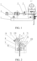
FIG. 1 is a schematic structural view of a device for separating supports for vacuum insulated glazing according to the present invention; -
FIG. 2 is a sectional view ofFIG. 1 taken along line A-A; -
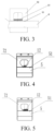
FIG. 3 is a schematic view showing a separation principle of the device for separating supports for vacuum insulated glazing according to the present invention; -
FIG. 4 is a schematic view of a convex accommodation cavity in which two sides of a convex portion at an upper end are set as slopes; -
FIG. 5 is a schematic view of a convex accommodation cavity in which one side of a convex portion at an upper end is set as a slope; -
FIG. 6 is a partial enlarged view of Part C inFIG. 2 ; -
FIG. 7 is a schematic structural view of a system for arranging supports for vacuum insulated glazing when viewed from the front; -
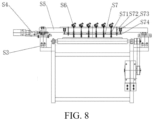
FIG. 8 is a schematic structural view of the system for arranging supports for vacuum insulated glazing when viewed from the left; -
FIG. 9 is a schematic structural view of the system for arranging supports for vacuum insulated glazing when viewed from the top; -
FIG. 10 is a schematic structural view of a blanking assembly; -
FIG. 11 is a partial enlarged view of Part B inFIG. 10 ; -
FIG. 12 is a schematic view of a side surface of the support; -
FIG. 13(a) is a schematic view of a support with a quadrilateral cross section;FIG. 13(b) is a schematic view of a support with a pentagonal cross section;FIG. 13(c) is a schematic view of a support with a hexagonal cross section;FIG. 13(d) is a schematic view of a support with a round cross section; -
FIG. 14 is a front view of a separation actuator; and -
FIG. 15 is a side view of the separation actuator. - In the
figures: 1 , base; 2, cylinder mounting frame; 3, cylinder; 4, separation plate fixing block; 5, separation plate; 51, separation recess; 6, hopper; 7, separation chamber assembly; 71, upper separation chamber plate; 72, lower separation chamber plate; 8, feed tube; 9, optical fiber sensor; 10, feed tube clamp; 11, vibrator; 12, support; 13, limit baffle; 131, upper baffle; 132, lower baffle; and 14, bottom plate. - S1, transmission section; S11, transmission frame; S12, transmission power; S13, transmission roller table; S2, glazing; S3, transverse movement bracket; S4, transverse movement control mechanism; S5, support beam; S6, separation device; S7, feed tube lifting mechanism; S71, blanking assembly; S711, feed tube; S712, guide sleeve; S713, compression spring; S714, transition joint; S72, guide assembly; S73, lifting power; and S74, fixing plate.
- The present invention is described in more detail below with embodiments. The present invention may be embodied in many different forms and should not be construed as being limited to the exemplary embodiments set forth herein.
- For ease of description, space-related terms, such as "up", "down", "left", and "right", may be used herein for describing a relationship between one element or feature and another element or feature as shown in the figures. It should be understood that, the space terms are intended to encompass different orientations of the device in use or operation other than the orientations described in the figures.
- For example, if the device in the figure is inverted, the element described as "below" other elements or features will be oriented "above" the other elements or features. Therefore, the exemplary term "below" may include both above and below. The device may be oriented in other ways (rotated by 90 degrees or in other orientations), and the spatially relative description used herein can be interpreted accordingly.
- A
support 12 may be in a round pie shape or in a pie shape with a polygonal cross section (as shown inFIG. 12 and FIG. 13 ). Here, a round pie-shaped object having a diameter of 0.5 mm-0.9 mm and a thickness of 0.2 mm-0.4 mm is taken as an example for description. As shown inFIG. 1 and FIG. 2 , a device for separating supports for vacuum insulated glazing in this embodiment includes abase 1, ahopper 6, avibrator 11, aseparation chamber assembly 7, alimit baffle 13, aseparation plate 5, a feed tube 8 and acylinder 3. Thecylinder 3 is provided at a side of thebase 1, and thehopper 6, theseparation chamber assembly 7, theseparation plate 5 and the feed tube 8 are sequentially provided at another side of thebase 1 from top to bottom. In order to avoid the blockage of the supports, thevibrator 11 is provided on theseparation chamber assembly 7. Vibrations generated by thevibrator 11 drive theseparation chamber assembly 7 to vibrate. Theseparation chamber assembly 7 is made of a wear-resistant and nonmagnetic material. The vibrations increase the fluidity of the granular supports, thereby ensuring thesupports 12 to be arranged loosely. Theseparation chamber assembly 7 includes an upperseparation chamber plate 71 and a lowerseparation chamber plate 72 disposed in parallel. The upperseparation chamber plate 71 is provided with an observation window for observing the state of the support in the convex accommodation cavity and the transportation of the support by theseparation plate 5. Theseparation chamber assembly 7 is disposed on abottom plate 14 inclined with respect to the horizontal plane. Thelimit baffle 13 is disposed outside theseparation chamber assembly 7. A clearance is left between thelimit baffle 13 and theseparation chamber assembly 7, such that theseparation chamber assembly 7 can vibrate. The upperseparation chamber plate 71 is provided with a feed inlet communicated with thehopper 6, and the lowerseparation chamber plate 72 is provided with a dispensing outlet communicated with the feed tube 8. The convex accommodation cavity is disposed on an end surface of the upperseparation chamber plate 71 away from thehopper 6 and/or an end surface of the lowerseparation chamber plate 72 close to thehopper 6. Theseparation plate 5 is movably provided at a lower portion of the convex accommodation cavity and connected to thecylinder 3, and is driven by thecylinder 3 to make reciprocating movements along the lower portion of the accommodation cavity. A convex portion at an upper end of the convex accommodation cavity is communicated with thehopper 6 via the feed inlet. An upper edge of theseparation plate 5 at a side close to the convex portion at the upper end of the convex accommodation cavity is provided with aseparation recess 51. On the plane where theseparation plate 5 is located, the reciprocating movement direction is the width direction, the direction perpendicular to the reciprocating movement is the height direction, and the direction perpendicular to the plane where theseparation plate 5 is located is the thickness direction. Theseparation plate 5 is in a clearance fit with the lower portion of the convex accommodation cavity. The clearance should be less than a thickness d1 of thesupport 12, to prevent thesupport 12 from running out of the convex portion at the upper end of the convex accommodation cavity via the clearance during the reciprocating movements of theseparation plate 5. A thickness d of the convex accommodation cavity is greater than a thickness d1 of thesupport 12, and the thickness d of the convex accommodation cavity is less than a cross-sectional diameter d2 of thesupport 12, so that thesupports 12 can only be arranged with its bottom surface falling on the lowerseparation chamber plate 72 under the vibrations of the separation chamber assembly inclinedly arranged with respect to the horizontal plane. The thickness d of the convex accommodation cavity is less than twice the thickness d1 of thesupport 12, which prevents the supports in the convex accommodation cavity from being arranged in double layers. A width w of theseparation recess 51 is less than a width w1 of theseparation plate 5. A thickness d3 of theseparation plate 5 is greater than the thickness d1 of thesupport 12. A height h of theseparation recess 51 is greater than the cross-sectional diameter d2 of thesupport 12 by 0.1 mm-0.2 mm, and the width w of theseparation recess 51 is greater than the cross-sectional diameter d2 of thesupport 12 by 0.1 mm-0.2 mm, so that thesupport 12 can smoothly enter theseparation recess 51 and theseparation recess 51 can only accommodate one support. - A drive mechanism is mounted on the
base 1. The drive mechanism may be thecylinder 3. A cylinder block of thecylinder 3 is fixed to thebase 1 via acylinder mounting frame 2. A piston rod is fixedly connected to theseparation plate 5 via a separationplate fixing block 4. - An
upper baffle 131 and alower baffle 132 are disposed outside theseparation chamber assembly 7. The upperseparation chamber plate 71, the lowerseparation chamber plate 72 and thebottom plate 14 are assembled together via the L-shapedupper baffle 131 and thelower baffle 132. Thebottom plate 14 is fixed to thebase 1 inclinedly with respect to the horizontal plane. - The distance of the reciprocating movement of the
separation plate 5 is such that thesupport 12 is conveyed into the dispensing outlet at a connecting channel between the lowerseparation chamber plate 72 and the feed tube 8 after theseparation recess 51 obtains thesupport 12 from the convex accommodation cavity. - As shown in
FIG. 4 and FIG. 5 , one or two sides of the convex portion at the upper end of the convex accommodation cavity may be provided with a slope or slopes communicated with theseparation plate 5 via a channel at the bottom of the slope, which further reduces the advancing resistance of the separation plate carrying thesupport 12. - The separation actuator is not limited to the plate-shaped separation actuator in the figure, and may also be a rod-shaped separation actuator. When the separation actuator is a round rod, the end portion should be treated, for example perforated, to ensure that the recess is on the top surface during mounting.
- As shown in
FIG. 3 , a lower edge of the separation actuator at a side away from the convex portion at the upper end of the convex accommodation cavity may also be provided with theseparation recess 51 capable of accommodating one support. After the recess at the side of theseparation plate 5 close to the convex portion at the upper end of the convex accommodation cavity is worn, the separation plate may be turned over, which prolongs the service life of the separation actuator. - In order to detect the separation failure in time, the feed tube 8 is a transparent tube made of glass or other transparent materials, and a sensor is provided on a wall of the feed tube 8 to detect whether a support falls. The sensor is fixed to the feed tube 8 via a
feed tube clamp 10. - The sensor is an
optical fiber sensor 9, which has higher detection sensitivity. - An included angle between the
bottom plate 14 and the horizontal plane is 25° to 75°. In this way, the granular supports can be moved by gravity, and the supports can be prevented from excessively extruded by the gravity, which makes the pile of the supports easily loosened and ensures the smooth flow of the granular supports. - An inner diameter of the feed tube 8 is greater than a diameter of the
support 12 by 0.1 mm-0.2 mm, so that thesupports 12 can pass through smoothly. - In the embodiments, the
separation plate 5 may be pushed to make the reciprocating movements by thecylinder 3 or an electric cylinder; or theseparation plate 5 may be pushed to make the reciprocating movements by a crank-connecting rod mechanism driven by a stepping motor. - In the working process, the demagnetized supports 12 are added via the
hopper 6 at the top. The vibrator is started such that thesupports 12 are loosely arranged in one layer in a sequence of entering the convex accommodation cavity. Thecylinder 3 is started to push theseparation plate 5. Under the action of the vibrator, thesupports 12 fall into theseparation recess 51 of theseparation plate 5 at an end close to the convex portion at the upper end of the convex accommodation cavity. Theseparation plate 5 moves rightward to convey thesupport 12 in theseparation recess 51 to the dispensing outlet. Thecylinder 3 stops driving, and thesupport 12 passes through thebottom plate 14 via the dispensing outlet, enters the feed tube 8, and is discharged via the bottom end of the feed tube 8. Thecylinder 3 acts in the reverse direction, and theseparation plate 5 retracts, so that theseparation recess 51 enters the convex portion at the upper end of the convex accommodation cavity. - The glazing conveying direction is set as the longitudinal direction, and the direction perpendicular to the glazing conveying direction is set as the transverse direction. As shown in
FIG. 7 to FIG. 9 , a system for arranging supports for vacuum insulated glazing in this embodiment includes a transmission section S1, a control system (not shown) and a separation devices S6. The transmission section S1 includes atransmission frame S1 1 and a transmission roller table S13 on the transmission frame S11. Transmission power S12 provides a driving force for the transmission roller table S13. Generally, the motor drives the transmission roller table S13 via a belt or a sprocket after a reducer. When a servo motor is used, the speed reducer may also be omitted. The control system is a PLC control system located in an electrical control cabinet of a vacuum insulated glazing production line. The PLC control system is electrically connected to a transmission power S12 device of the transmission roller table S13 and the separation device S6, and controls the rotation of the transmission roller table S13 and the separation and arrangement of thesupport 12. Glazing S2 is placed on the transmission roller table S13 and is capable of moving back and forth along the transmission roller table S13. The top surface of the transmission frame S11 and the left and right sides of the transmission roller table S13 are respectively provided with a transverse movement bracket S3, and a support beam S5 is disposed over the transverse movement bracket S3. One end of the support beam S5 is further provided with a transverse movement control mechanism S4, so that the separation device S6 can move transversely along the support beam S5. The transverse movement bracket S3 is disposed horizontally. In the figure, the transverse movement bracket S3 is disposed in a direction perpendicular to the movement direction of the glazing S2, and may also be disposed inclinedly at an angle of 45 degrees, 30 degrees, etc. with the movement direction of the glazing S2. The separation device S6 is disposed on the support beam S5 via thebase 1. There may be one or more separation devices S6. In this embodiment, there are six separation devices S6. The separation devices S6 are linearly arranged on the support beam S5 at intervals. In other embodiments of the present invention, the separation devices may be arranged on the support beam S5 at intervals in an array. - In order to arrange the
supports 12, the system is further provided with a feed tube lifting mechanism S7. When the system is arranging the supports, a blanking assembly S71 descends, the separation devices S6 separate thesupports 12, thesupport 12 falls off from the feed tube 8, and theoptical fiber sensor 9 detects the passage of the support. The support stops on the surface of the glazing S2 via the blanking assembly S71. When theoptical fiber sensor 9 of one or more of the separation devices S6 does not detect the passage of the support, the PLC control system controls the corresponding separation device S6 to execute the separation operation again until theoptical fiber sensor 9 detects the passage of the support. Then, the blanking assembly S71 ascends, which prevents thesupport 12 from colliding with the lower end of the blanking assembly S71 when the glazing S2 moves forward. After the blanking assembly S71 ascends to the appropriate position, the transmission roller table S13 rotates to drive the glazing S2 to move forward by one step, and then thesupport 12 is placed again, thereby forming an array of the supports on the surface of the glazing S2. In other embodiments of the present invention, the glazing may be kept still. The movement control mechanism includes a transverse movement control mechanism S4 and a longitudinal movement control mechanism. The longitudinal movement control mechanism controls the longitudinal step-by-step movement of the support beam S5. The longitudinal movement control mechanism is electrically connected to the PLC control system. After the blanking assembly S71 ascends to the appropriate position, the longitudinal movement control mechanism drives the support beam S5 to move by one step, and then thesupport 12 is arranged again, thereby forming an array of the supports on the surface of the glazing S2. - As shown in
FIG. 10 , the blanking assembly S71 includes a feed tube S711, a guide sleeve S712, a compression spring S713 and a transition joint S714. The feed tube 8 of the separation device S6 is inserted into a material through hole at the center of the feed tube S711, and a clearance is provided between an outer wall of the feed tube 8 and an inner wall of the material through hole. An upper end of the feed tube S711 is provided with a stepped surface. The stepped surface has a larger outer diameter at the upper end and a smaller outer diameter at the lower end. The guide sleeve S712 is sleeved on a smaller end of the feed tube S711, and the compression spring S713 and the transition joint S714 are sequentially arranged below the guide sleeve. The transition joint S714 is fixed to the lower end of the feed tube S711 by a thread, a snap-in hole or a pin. The guide sleeve S712 and the transition joint S714 clamp the compression spring S713 in a compressed state. The guide sleeve S712 is fixed to a fixing plate S74. When the fixing plate S74 descends, the compression spring S713 pushes the transition joint S714, so that a lower end surface of the transition joint S714 is in close contact with the surface of the glazing S2. When the fixing plate S74 ascends, the guide sleeve S712 drives the feed tube S711 to ascend via the stepped surface. - The support beam S5 is further provided with a feed tube lifting mechanism S7. The feed tube lifting mechanism S7 includes a guide assembly S72, lifting power S73 and a fixing plate S74. The guide assembly S72 is composed of a guide sleeve and a guide rod. The lifting power S73 is provided by an electric cylinder or a cylinder. The lifting power S73 drives the fixing plate S74 to move up and down.
- As shown in
FIG. 11 , an inner cavity of the transition joint S714 is provided with an inverted conical transition section, and the inner cavity of the transition joint S714 has a trumpet-shaped bottom, so that thesupports 12 can be accurately located on the glazing S2 after being sorted via the transition section, which prevents the support from bouncing off its proper position or bouncing off the glazing S2. - Beneficial effects:
- 1. The convex accommodation cavity forms an included angle with the horizontal direction, so that the supports can be automatically arranged in sequence in one layer when being added.
- 2. Under the action of the vibrations, a clearance is formed in the separation process, and thus the support can quickly and accurately enter the recesses of the separation plates, which increases the success rate of separation of the supports.
- 3. The thickness of the support is less than the thickness of the separation plate, so that a small clearance is left between the support and the convex accommodation cavity in the separation process, which reduces wear.
- 4. When the system is arranging the supports, one reciprocating movement of the separation plate can only transport one support, thereby eliminating the case in which multiple supports are arranged in one operation.
- 5. With the optical fiber sensor added to detect the passage of the support, when there is no support falling off, the separation operation is restarted until the optical fiber sensor detects the passage of the support, so that every recess can accommodate one support after the separation operation.
- The foregoing examples are only intended to illustrate the present invention, and in addition, there are a number of different embodiments that will be conceivable to a person skilled in the art upon understanding the present invention, and examples are not listed herein.
Claims (10)
- A device for separating supports (12) for vacuum insulated glazing, comprising a base (1), a vibrator (11), a separation chamber assembly (7), a separation actuator, a feed tube (8), and a drive device, wherein the drive device is provided at a side of the base and connected to the separation actuator wherein the drive device is adapted to push the separation actuator to make reciprocating movements, and the separation chamber assembly, the separation actuator and the feed tube are sequentially provided at another side of the base from top to bottom; the vibrator is provided on the separation chamber assembly; the separation chamber assembly is provided with a feed inlet, an accommodation cavity, and a dispensing outlet, the feed inlet is communicated with the accommodation cavity, the dispensing outlet is communicated with the feed tube, and the separation chamber assembly is inclinedly arranged with respect to a horizontal plane; the separation actuator passes through the separation chamber assembly, and is provided at a lower portion of the accommodation cavity in a reciprocatingly movable manner; an upper edge of the separation actuator at a side close to the dispensing outlet is provided with a recess (51) capable of accommodating one support; and during reciprocating movements of the separation actuator, the accommodation cavity is communicated with the dispensing outlet via the recess of the separation actuator.
- The device for separating supports for vacuum insulated glazing according to claim 1, further comprising a hopper (6) and a limit baffle (13), wherein the separation chamber assembly is disposed on a bottom plate inclined with respect to the horizontal plane through the limit baffle, the separation chamber assembly comprises an upper separation chamber plate (71) and a lower separation chamber plate (72) disposed in parallel, the upper separation chamber plate is provided with the feed inlet, and the lower separation chamber plate is provided with the dispensing outlet; the accommodation cavity is a convex accommodation cavity disposed on an end surface of the upper separation chamber plate away from the hopper and/or an end surface of the lower separation chamber plate close to the hopper; a convex portion at an upper end of the convex accommodation cavity is provided with the feed inlet communicated with the hopper, the lower portion of the convex accommodation cavity is provided with the dispensing outlet communicated with the recess of the separation actuator, and the separation actuator makes the reciprocating movements along the lower portion of the convex accommodation cavity.
- The device for separating supports for vacuum insulated glazing according to claim 2, wherein assuming that a thickness of the convex accommodation cavity is d, a thickness of the support is d1 and a maximum distance between any two points on a cross section of the support is d2, then d1<d<d2, and d<2dl.
- The device for separating supports for vacuum insulated glazing according to claim 1, wherein assuming that a height of the recess of the separation actuator is h, a width of the recess of the separation actuator is w and a maximum distance between any two points on a cross section of the support is d2, then d2<h, d2<w, a difference between d2 and h is in a range of 0.01 mm-0.5 mm, and a difference between d2 and w is in a range of 0.01 mm-0.5 mm.
- The device for separating supports for vacuum insulated glazing according to claim 4, wherein the difference between d2 and h is in the range of 0.1 mm-0.2 mm, and the difference between d2 and w is in the range of 0.1 mm-0.2 mm.
- The device for separating supports for vacuum insulated glazing according to claim 1, wherein the feed tube is a transparent tube, and a wall of the feed tube is provided with a sensor (9).
- The device for separating supports for vacuum insulated glazing according to either of claim 1 or 6, wherein assuming that an inner diameter of the feed tube is r and a maximum distance between any two points on a cross section of the support is d2, then r>d2, and a difference between r and d2 is in a range of 0.01 mm-0.5 mm.
- A method for separating supports for vacuum insulated glazing using the device for separating supports for vacuum insulated glazing according to any of claims 1 to 7, comprising the following steps:step I: starting a vibrator such that the supports in a hopper are sequentially and loosely arranged in one layer in an accommodation cavity through a feed inlet;step II: starting a drive device to push a separation actuator such that any of the supports on a bottom layer in the accommodation cavity quickly and accurately enters the recess of the separation actuator under the action of the vibrator, and when a recess of the separation actuator coincides with a dispensing outlet, stopping the drive device;step III: after the support falls into a feed tube, if the sensor detects the passage of the support, completing the separation operation; andstep IV: if the sensor does not detect the passage of the support, repeating step I to step III until the sensor detects the passage of the support, and completing the separation operation.
- A system for arranging supports for vacuum insulated glazing, comprising a transmission section (S1),a control system and a plurality of the devices for separating supports for vacuum insulated glazing according to any of claims 1 to 7, wherein the transmission section comprises a frame (S11) and a transmission roller table (S13) a disposed on the frame, and the frame is provided with a support beam (S5);and the separation devices are linearly arranged on the support beam at intervals and perform a support separation operation at the same time, so that the arrangement of the supports in one row in the vacuum insulated glazing is completed by one or more operations; or the plurality of devices for separating supports for vacuum insulated glazing according to any of claims 1 to 7 are arranged on the support beam in an array and perform the support separation operation at the same time, so that the arrangement of the supports in one area is completed by one or more operations.
- A method for arranging supports for vacuum insulated glazing using the system for arranging supports for vacuum insulated glazing according to claim 9, comprising the following steps:step I: separating the supports by using the method for separating supports for vacuum insulated glazing according to claim 8;step II: enabling the separation devices to move step by step with respect to the glazing; andstep III: repeating step I and step II until a surface of the glazing is covered with the supports, and completing the arrangement operation.
Applications Claiming Priority (2)
| Application Number | Priority Date | Filing Date | Title |
|---|---|---|---|
| CN202010284983.1A CN111517098B (en) | 2020-04-13 | 2020-04-13 | Vacuum glass support separating and arranging device and method |
| PCT/CN2021/079067 WO2021208628A1 (en) | 2020-04-13 | 2021-03-04 | Device for separately arranging supports for vacuum insulated glazing, and method |
Publications (4)
| Publication Number | Publication Date |
|---|---|
| EP4137427A1 EP4137427A1 (en) | 2023-02-22 |
| EP4137427A4 EP4137427A4 (en) | 2023-09-27 |
| EP4137427B1 true EP4137427B1 (en) | 2024-04-24 |
| EP4137427C0 EP4137427C0 (en) | 2024-04-24 |
Family
ID=71902284
Family Applications (1)
| Application Number | Title | Priority Date | Filing Date |
|---|---|---|---|
| EP21788449.3A Active EP4137427B1 (en) | 2020-04-13 | 2021-03-04 | Device for separately arranging supports for vacuum insulated glazing, and method |
Country Status (7)
| Country | Link |
|---|---|
| US (1) | US12624590B2 (en) |
| EP (1) | EP4137427B1 (en) |
| JP (1) | JP7407304B2 (en) |
| KR (1) | KR102833735B1 (en) |
| CN (1) | CN111517098B (en) |
| AU (1) | AU2021255243B2 (en) |
| WO (1) | WO2021208628A1 (en) |
Families Citing this family (7)
| Publication number | Priority date | Publication date | Assignee | Title |
|---|---|---|---|---|
| CN111517098B (en) | 2020-04-13 | 2022-02-18 | 洛阳兰迪玻璃机器股份有限公司 | Vacuum glass support separating and arranging device and method |
| CN112607446A (en) * | 2020-11-24 | 2021-04-06 | 洛阳兰迪玻璃机器股份有限公司 | Automatic support sequencing mechanism, support separating device and support distributing system |
| EP4357579A1 (en) | 2022-10-19 | 2024-04-24 | VKR Holding A/S | Spacer outlet distance control during vig unit manufacturing by means of a distance controller |
| WO2024083529A1 (en) | 2022-10-19 | 2024-04-25 | Vkr Holding A/S | Vig unit production comprising use of a dispenser comprising a collection sheet |
| EP4357576A1 (en) | 2022-10-19 | 2024-04-24 | VKR Holding A/S | Vig unit production comprising use of a dispenser comprising a collection sheet |
| EP4571032B1 (en) | 2023-12-12 | 2026-04-29 | VKR Holding A/S | Dispenser comprising one or more protruding members extending into a spacer storage compartment |
| EP4571033A1 (en) | 2023-12-12 | 2025-06-18 | VKR Holding A/S | Detection of jamming situation during vig unit manufacturing |
Family Cites Families (24)
| Publication number | Priority date | Publication date | Assignee | Title |
|---|---|---|---|---|
| US2429891A (en) * | 1944-08-07 | 1947-10-28 | Jack & Heintz Prec Ind Inc | Electrically responsive gaging mechanism for assorting bearing balls |
| US2577611A (en) * | 1947-01-02 | 1951-12-04 | American Optical Corp | Device for hardening |
| US2953959A (en) * | 1956-07-19 | 1960-09-27 | Fed Lab Inc | Filling machine |
| US3670928A (en) * | 1970-01-26 | 1972-06-20 | Roy R Hanson | Powder metering device for loading ammunition |
| DD254731A1 (en) * | 1986-12-17 | 1988-03-09 | Torgau Flachglas | DEVICE FOR FILLING THE SPACERS FOR INSULATING GLASSES |
| DE3710694A1 (en) * | 1987-03-31 | 1988-10-13 | Karl Lenhardt | Process and device for filling straight hollow-profile members for spacer frames in insulating glass panes with a granular desiccant |
| US6681550B1 (en) * | 2002-08-13 | 2004-01-27 | Aylward Enterprises, Inc. | Apparatus and methods for filling containers with pills |
| KR100849529B1 (en) | 2007-10-04 | 2008-08-01 | 하양호 | Vacuum Laminated Glass Manufacturing Method |
| CN101698565B (en) * | 2009-11-16 | 2011-12-07 | 黑龙江省农业科学院农村能源研究所 | Distribution system of magnetic supports in vacuum glass |
| US9822580B2 (en) * | 2011-02-22 | 2017-11-21 | Guardian Glass, LLC | Localized heating techniques incorporating tunable infrared element(s) for vacuum insulating glass units, and/or apparatuses for same |
| CN203346285U (en) * | 2013-05-17 | 2013-12-18 | 洛阳兰迪玻璃机器股份有限公司 | Spherical middle supporting subject particle separation device for vacuum glass |
| CN103253874B (en) | 2013-05-17 | 2015-08-26 | 洛阳兰迪玻璃机器股份有限公司 | As separation method and the application thereof of the spheroidal particle of vacuum glass middle support |
| CN203668211U (en) * | 2013-12-18 | 2014-06-25 | 洛阳兰迪玻璃机器股份有限公司 | Vacuum glass support particle laying system |
| CN106045286B (en) * | 2016-07-29 | 2019-04-02 | 洛阳兰迪玻璃机器股份有限公司 | A kind of separation method, separation device and distribution system of support particles |
| CN106494832A (en) * | 2016-09-22 | 2017-03-15 | 广西大学 | A kind of electro-vibrating feeder |
| CN107089489B (en) | 2017-05-22 | 2022-11-04 | 江门市宏丰电子科技有限公司 | Take charactron discharging machine of automated inspection and direction of rotation function |
| CN207175785U (en) * | 2017-08-16 | 2018-04-03 | 北京明旭真空玻璃技术有限公司 | A kind of vacuum glass support placement device |
| CN207632140U (en) * | 2017-12-26 | 2018-07-20 | 天津壮特五金工业有限公司 | A kind of auto-induction type iron nail processing self-feeding bucket |
| CN108503241B (en) * | 2018-05-18 | 2023-07-25 | 洛阳兰迪玻璃机器股份有限公司 | Method and device for deploying a support |
| CN208500772U (en) * | 2018-05-18 | 2019-02-15 | 洛阳兰迪玻璃机器股份有限公司 | A support placement device |
| CN208500771U (en) * | 2018-05-18 | 2019-02-15 | 洛阳兰迪玻璃机器股份有限公司 | A support placement device |
| CN208716439U (en) * | 2018-09-07 | 2019-04-09 | 深圳孔雀科技开发有限公司 | A kind of vacuum glass support tapping equipment |
| CN212127984U (en) * | 2020-04-13 | 2020-12-11 | 洛阳兰迪玻璃机器股份有限公司 | Vacuum glass support distribution system |
| CN111517098B (en) * | 2020-04-13 | 2022-02-18 | 洛阳兰迪玻璃机器股份有限公司 | Vacuum glass support separating and arranging device and method |
-
2020
- 2020-04-13 CN CN202010284983.1A patent/CN111517098B/en active Active
-
2021
- 2021-03-04 JP JP2022560512A patent/JP7407304B2/en active Active
- 2021-03-04 AU AU2021255243A patent/AU2021255243B2/en active Active
- 2021-03-04 KR KR1020227033885A patent/KR102833735B1/en active Active
- 2021-03-04 US US17/918,174 patent/US12624590B2/en active Active
- 2021-03-04 EP EP21788449.3A patent/EP4137427B1/en active Active
- 2021-03-04 WO PCT/CN2021/079067 patent/WO2021208628A1/en not_active Ceased
Also Published As
| Publication number | Publication date |
|---|---|
| US12624590B2 (en) | 2026-05-12 |
| AU2021255243B2 (en) | 2023-11-30 |
| WO2021208628A1 (en) | 2021-10-21 |
| EP4137427A1 (en) | 2023-02-22 |
| KR20220146619A (en) | 2022-11-01 |
| KR102833735B1 (en) | 2025-07-15 |
| CN111517098A (en) | 2020-08-11 |
| AU2021255243A1 (en) | 2022-12-01 |
| EP4137427A4 (en) | 2023-09-27 |
| EP4137427C0 (en) | 2024-04-24 |
| CN111517098B (en) | 2022-02-18 |
| US20240052689A1 (en) | 2024-02-15 |
| JP2023520567A (en) | 2023-05-17 |
| JP7407304B2 (en) | 2023-12-28 |
Similar Documents
| Publication | Publication Date | Title |
|---|---|---|
| EP4137427A1 (en) | Device for separately arranging supports for vacuum insulated glazing, and method | |
| CN109264359B (en) | Touch screen feeding equipment | |
| CN212127984U (en) | Vacuum glass support distribution system | |
| CN106927244B (en) | High-speed transfer robot system of photovoltaic panel | |
| CN115656759A (en) | Semiconductor test braid all-in-one | |
| CN113765307A (en) | Motor shell riveting center shaft and automatic rotor assembling equipment | |
| CN103495866A (en) | Automatic assembling machine of small sensitive switch | |
| CN112171275B (en) | Alloy button assembling machine | |
| CN114348596A (en) | Automatic welding, assembling and packaging machine | |
| US8083462B2 (en) | Apparatus for placing battery plates in a line | |
| CN110757148A (en) | Automatic assembling and shaping method for photoelectric switch | |
| CN108520839A (en) | A photoelectric switch automatic assembly shaping and cutting equipment and method | |
| CN204777489U (en) | Automatic feeding device that opens and shuts links | |
| CN103640316B (en) | Automatic glue pressing machine | |
| CN106112508B (en) | Automatic assembly equipment for watch parts | |
| CN209822513U (en) | Automatic assembling equipment for button switch | |
| CN224090537U (en) | Batch feeder and batch feeder | |
| CN223920495U (en) | A vibration feeding mechanism for battery cover is carried | |
| CN205060045U (en) | Pellet unloading system | |
| CN209567480U (en) | A new type of bearing feeder | |
| CN205917169U (en) | Support particle separation device and cloth system of putting thereof | |
| CN110421329B (en) | System based on production of LED bulb lamp | |
| CN218950339U (en) | An automatic deviation correcting and distributing device | |
| CN222904901U (en) | An automatic production line for hose crimping | |
| CN219057524U (en) | Feeding device and upper row production line thereof |
Legal Events
| Date | Code | Title | Description |
|---|---|---|---|
| STAA | Information on the status of an ep patent application or granted ep patent |
Free format text: STATUS: THE INTERNATIONAL PUBLICATION HAS BEEN MADE |
|
| PUAI | Public reference made under article 153(3) epc to a published international application that has entered the european phase |
Free format text: ORIGINAL CODE: 0009012 |
|
| STAA | Information on the status of an ep patent application or granted ep patent |
Free format text: STATUS: REQUEST FOR EXAMINATION WAS MADE |
|
| 17P | Request for examination filed |
Effective date: 20221004 |
|
| AK | Designated contracting states |
Kind code of ref document: A1 Designated state(s): AL AT BE BG CH CY CZ DE DK EE ES FI FR GB GR HR HU IE IS IT LI LT LU LV MC MK MT NL NO PL PT RO RS SE SI SK SM TR |
|
| DAV | Request for validation of the european patent (deleted) | ||
| DAX | Request for extension of the european patent (deleted) | ||
| A4 | Supplementary search report drawn up and despatched |
Effective date: 20230825 |
|
| RIC1 | Information provided on ipc code assigned before grant |
Ipc: E06B 3/673 20060101ALI20230821BHEP Ipc: E06B 3/663 20060101ALI20230821BHEP Ipc: C03C 27/06 20060101ALI20230821BHEP Ipc: B65G 47/88 20060101ALI20230821BHEP Ipc: B65G 47/14 20060101AFI20230821BHEP |
|
| GRAP | Despatch of communication of intention to grant a patent |
Free format text: ORIGINAL CODE: EPIDOSNIGR1 |
|
| STAA | Information on the status of an ep patent application or granted ep patent |
Free format text: STATUS: GRANT OF PATENT IS INTENDED |
|
| RIC1 | Information provided on ipc code assigned before grant |
Ipc: E06B 3/673 20060101ALI20231024BHEP Ipc: E06B 3/663 20060101ALI20231024BHEP Ipc: C03C 27/06 20060101ALI20231024BHEP Ipc: B65G 47/88 20060101ALI20231024BHEP Ipc: B65G 47/14 20060101AFI20231024BHEP |
|
| INTG | Intention to grant announced |
Effective date: 20231128 |
|
| GRAS | Grant fee paid |
Free format text: ORIGINAL CODE: EPIDOSNIGR3 |
|
| GRAA | (expected) grant |
Free format text: ORIGINAL CODE: 0009210 |
|
| STAA | Information on the status of an ep patent application or granted ep patent |
Free format text: STATUS: THE PATENT HAS BEEN GRANTED |
|
| AK | Designated contracting states |
Kind code of ref document: B1 Designated state(s): AL AT BE BG CH CY CZ DE DK EE ES FI FR GB GR HR HU IE IS IT LI LT LU LV MC MK MT NL NO PL PT RO RS SE SI SK SM TR |
|
| REG | Reference to a national code |
Ref country code: GB Ref legal event code: FG4D |
|
| REG | Reference to a national code |
Ref country code: CH Ref legal event code: EP |
|
| REG | Reference to a national code |
Ref country code: DE Ref legal event code: R096 Ref document number: 602021012401 Country of ref document: DE |
|
| REG | Reference to a national code |
Ref country code: IE Ref legal event code: FG4D |
|
| U01 | Request for unitary effect filed |
Effective date: 20240429 |
|
| U07 | Unitary effect registered |
Designated state(s): AT BE BG DE DK EE FI FR IT LT LU LV MT NL PT SE SI Effective date: 20240506 |
|
| PG25 | Lapsed in a contracting state [announced via postgrant information from national office to epo] |
Ref country code: IS Free format text: LAPSE BECAUSE OF FAILURE TO SUBMIT A TRANSLATION OF THE DESCRIPTION OR TO PAY THE FEE WITHIN THE PRESCRIBED TIME-LIMIT Effective date: 20240824 |
|
| PG25 | Lapsed in a contracting state [announced via postgrant information from national office to epo] |
Ref country code: HR Free format text: LAPSE BECAUSE OF FAILURE TO SUBMIT A TRANSLATION OF THE DESCRIPTION OR TO PAY THE FEE WITHIN THE PRESCRIBED TIME-LIMIT Effective date: 20240424 |
|
| PG25 | Lapsed in a contracting state [announced via postgrant information from national office to epo] |
Ref country code: GR Free format text: LAPSE BECAUSE OF FAILURE TO SUBMIT A TRANSLATION OF THE DESCRIPTION OR TO PAY THE FEE WITHIN THE PRESCRIBED TIME-LIMIT Effective date: 20240725 |
|
| PG25 | Lapsed in a contracting state [announced via postgrant information from national office to epo] |
Ref country code: ES Free format text: LAPSE BECAUSE OF FAILURE TO SUBMIT A TRANSLATION OF THE DESCRIPTION OR TO PAY THE FEE WITHIN THE PRESCRIBED TIME-LIMIT Effective date: 20240424 |
|
| PG25 | Lapsed in a contracting state [announced via postgrant information from national office to epo] |
Ref country code: PL Free format text: LAPSE BECAUSE OF FAILURE TO SUBMIT A TRANSLATION OF THE DESCRIPTION OR TO PAY THE FEE WITHIN THE PRESCRIBED TIME-LIMIT Effective date: 20240424 |
|
| PG25 | Lapsed in a contracting state [announced via postgrant information from national office to epo] |
Ref country code: PL Free format text: LAPSE BECAUSE OF FAILURE TO SUBMIT A TRANSLATION OF THE DESCRIPTION OR TO PAY THE FEE WITHIN THE PRESCRIBED TIME-LIMIT Effective date: 20240424 Ref country code: NO Free format text: LAPSE BECAUSE OF FAILURE TO SUBMIT A TRANSLATION OF THE DESCRIPTION OR TO PAY THE FEE WITHIN THE PRESCRIBED TIME-LIMIT Effective date: 20240724 Ref country code: IS Free format text: LAPSE BECAUSE OF FAILURE TO SUBMIT A TRANSLATION OF THE DESCRIPTION OR TO PAY THE FEE WITHIN THE PRESCRIBED TIME-LIMIT Effective date: 20240824 Ref country code: HR Free format text: LAPSE BECAUSE OF FAILURE TO SUBMIT A TRANSLATION OF THE DESCRIPTION OR TO PAY THE FEE WITHIN THE PRESCRIBED TIME-LIMIT Effective date: 20240424 Ref country code: GR Free format text: LAPSE BECAUSE OF FAILURE TO SUBMIT A TRANSLATION OF THE DESCRIPTION OR TO PAY THE FEE WITHIN THE PRESCRIBED TIME-LIMIT Effective date: 20240725 Ref country code: ES Free format text: LAPSE BECAUSE OF FAILURE TO SUBMIT A TRANSLATION OF THE DESCRIPTION OR TO PAY THE FEE WITHIN THE PRESCRIBED TIME-LIMIT Effective date: 20240424 Ref country code: RS Free format text: LAPSE BECAUSE OF FAILURE TO SUBMIT A TRANSLATION OF THE DESCRIPTION OR TO PAY THE FEE WITHIN THE PRESCRIBED TIME-LIMIT Effective date: 20240724 |
|
| PG25 | Lapsed in a contracting state [announced via postgrant information from national office to epo] |
Ref country code: CZ Free format text: LAPSE BECAUSE OF FAILURE TO SUBMIT A TRANSLATION OF THE DESCRIPTION OR TO PAY THE FEE WITHIN THE PRESCRIBED TIME-LIMIT Effective date: 20240424 |
|
| PG25 | Lapsed in a contracting state [announced via postgrant information from national office to epo] |
Ref country code: SK Free format text: LAPSE BECAUSE OF FAILURE TO SUBMIT A TRANSLATION OF THE DESCRIPTION OR TO PAY THE FEE WITHIN THE PRESCRIBED TIME-LIMIT Effective date: 20240424 Ref country code: RO Free format text: LAPSE BECAUSE OF FAILURE TO SUBMIT A TRANSLATION OF THE DESCRIPTION OR TO PAY THE FEE WITHIN THE PRESCRIBED TIME-LIMIT Effective date: 20240424 |
|
| REG | Reference to a national code |
Ref country code: DE Ref legal event code: R097 Ref document number: 602021012401 Country of ref document: DE |
|
| PG25 | Lapsed in a contracting state [announced via postgrant information from national office to epo] |
Ref country code: SM Free format text: LAPSE BECAUSE OF FAILURE TO SUBMIT A TRANSLATION OF THE DESCRIPTION OR TO PAY THE FEE WITHIN THE PRESCRIBED TIME-LIMIT Effective date: 20240424 |
|
| PG25 | Lapsed in a contracting state [announced via postgrant information from national office to epo] |
Ref country code: SM Free format text: LAPSE BECAUSE OF FAILURE TO SUBMIT A TRANSLATION OF THE DESCRIPTION OR TO PAY THE FEE WITHIN THE PRESCRIBED TIME-LIMIT Effective date: 20240424 Ref country code: SK Free format text: LAPSE BECAUSE OF FAILURE TO SUBMIT A TRANSLATION OF THE DESCRIPTION OR TO PAY THE FEE WITHIN THE PRESCRIBED TIME-LIMIT Effective date: 20240424 Ref country code: RO Free format text: LAPSE BECAUSE OF FAILURE TO SUBMIT A TRANSLATION OF THE DESCRIPTION OR TO PAY THE FEE WITHIN THE PRESCRIBED TIME-LIMIT Effective date: 20240424 Ref country code: CZ Free format text: LAPSE BECAUSE OF FAILURE TO SUBMIT A TRANSLATION OF THE DESCRIPTION OR TO PAY THE FEE WITHIN THE PRESCRIBED TIME-LIMIT Effective date: 20240424 |
|
| PLBE | No opposition filed within time limit |
Free format text: ORIGINAL CODE: 0009261 |
|
| STAA | Information on the status of an ep patent application or granted ep patent |
Free format text: STATUS: NO OPPOSITION FILED WITHIN TIME LIMIT |
|
| 26N | No opposition filed |
Effective date: 20250127 |
|
| U20 | Renewal fee for the european patent with unitary effect paid |
Year of fee payment: 5 Effective date: 20250225 |
|
| PG25 | Lapsed in a contracting state [announced via postgrant information from national office to epo] |
Ref country code: MC Free format text: LAPSE BECAUSE OF FAILURE TO SUBMIT A TRANSLATION OF THE DESCRIPTION OR TO PAY THE FEE WITHIN THE PRESCRIBED TIME-LIMIT Effective date: 20240424 |
|
| REG | Reference to a national code |
Ref country code: CH Ref legal event code: H13 Free format text: ST27 STATUS EVENT CODE: U-0-0-H10-H13 (AS PROVIDED BY THE NATIONAL OFFICE) Effective date: 20251024 |
|
| GBPC | Gb: european patent ceased through non-payment of renewal fee |
Effective date: 20250304 |
|
| PG25 | Lapsed in a contracting state [announced via postgrant information from national office to epo] |
Ref country code: GB Free format text: LAPSE BECAUSE OF NON-PAYMENT OF DUE FEES Effective date: 20250304 |
|
| PG25 | Lapsed in a contracting state [announced via postgrant information from national office to epo] |
Ref country code: CH Free format text: LAPSE BECAUSE OF NON-PAYMENT OF DUE FEES Effective date: 20250331 |
|
| PG25 | Lapsed in a contracting state [announced via postgrant information from national office to epo] |
Ref country code: IE Free format text: LAPSE BECAUSE OF NON-PAYMENT OF DUE FEES Effective date: 20250304 |
|
| U20 | Renewal fee for the european patent with unitary effect paid |
Year of fee payment: 6 Effective date: 20260226 |