EP4137359B1 - Fahrzeugsitz - Google Patents
Fahrzeugsitz Download PDFInfo
- Publication number
- EP4137359B1 EP4137359B1 EP22170533.8A EP22170533A EP4137359B1 EP 4137359 B1 EP4137359 B1 EP 4137359B1 EP 22170533 A EP22170533 A EP 22170533A EP 4137359 B1 EP4137359 B1 EP 4137359B1
- Authority
- EP
- European Patent Office
- Prior art keywords
- cavity
- section
- vehicle seat
- user
- support structure
- Prior art date
- Legal status (The legal status is an assumption and is not a legal conclusion. Google has not performed a legal analysis and makes no representation as to the accuracy of the status listed.)
- Active
Links
Images


Classifications
-
- B—PERFORMING OPERATIONS; TRANSPORTING
- B60—VEHICLES IN GENERAL
- B60N—SEATS SPECIALLY ADAPTED FOR VEHICLES; VEHICLE PASSENGER ACCOMMODATION NOT OTHERWISE PROVIDED FOR
- B60N2/00—Seats specially adapted for vehicles; Arrangement or mounting of seats in vehicles
- B60N2/24—Seats specially adapted for vehicles; Arrangement or mounting of seats in vehicles for particular purposes or particular vehicles
- B60N2/32—Seats specially adapted for vehicles; Arrangement or mounting of seats in vehicles for particular purposes or particular vehicles convertible for other use
- B60N2/34—Seats specially adapted for vehicles; Arrangement or mounting of seats in vehicles for particular purposes or particular vehicles convertible for other use into a bed
-
- B—PERFORMING OPERATIONS; TRANSPORTING
- B64—AIRCRAFT; AVIATION; COSMONAUTICS
- B64D—EQUIPMENT FOR FITTING IN OR TO AIRCRAFT; FLIGHT SUITS; PARACHUTES; ARRANGEMENT OR MOUNTING OF POWER PLANTS OR PROPULSION TRANSMISSIONS IN AIRCRAFT
- B64D11/00—Passenger or crew accommodation; Flight-deck installations not otherwise provided for
- B64D11/06—Arrangements of seats, or adaptations or details specially adapted for aircraft seats
- B64D11/0647—Seats characterised by special upholstery or cushioning features
-
- B—PERFORMING OPERATIONS; TRANSPORTING
- B60—VEHICLES IN GENERAL
- B60N—SEATS SPECIALLY ADAPTED FOR VEHICLES; VEHICLE PASSENGER ACCOMMODATION NOT OTHERWISE PROVIDED FOR
- B60N2/00—Seats specially adapted for vehicles; Arrangement or mounting of seats in vehicles
- B60N2/02—Seats specially adapted for vehicles; Arrangement or mounting of seats in vehicles the seat or part thereof being movable, e.g. adjustable
- B60N2/22—Seats specially adapted for vehicles; Arrangement or mounting of seats in vehicles the seat or part thereof being movable, e.g. adjustable the back-rest being adjustable
-
- B—PERFORMING OPERATIONS; TRANSPORTING
- B60—VEHICLES IN GENERAL
- B60N—SEATS SPECIALLY ADAPTED FOR VEHICLES; VEHICLE PASSENGER ACCOMMODATION NOT OTHERWISE PROVIDED FOR
- B60N2/00—Seats specially adapted for vehicles; Arrangement or mounting of seats in vehicles
- B60N2/64—Back-rests or cushions
- B60N2/643—Back-rests or cushions shape of the back-rests
-
- B—PERFORMING OPERATIONS; TRANSPORTING
- B60—VEHICLES IN GENERAL
- B60N—SEATS SPECIALLY ADAPTED FOR VEHICLES; VEHICLE PASSENGER ACCOMMODATION NOT OTHERWISE PROVIDED FOR
- B60N2/00—Seats specially adapted for vehicles; Arrangement or mounting of seats in vehicles
- B60N2/64—Back-rests or cushions
- B60N2/646—Back-rests or cushions shape of the cushion
-
- B—PERFORMING OPERATIONS; TRANSPORTING
- B64—AIRCRAFT; AVIATION; COSMONAUTICS
- B64D—EQUIPMENT FOR FITTING IN OR TO AIRCRAFT; FLIGHT SUITS; PARACHUTES; ARRANGEMENT OR MOUNTING OF POWER PLANTS OR PROPULSION TRANSMISSIONS IN AIRCRAFT
- B64D11/00—Passenger or crew accommodation; Flight-deck installations not otherwise provided for
- B64D11/06—Arrangements of seats, or adaptations or details specially adapted for aircraft seats
- B64D11/0639—Arrangements of seats, or adaptations or details specially adapted for aircraft seats with features for adjustment or converting of seats
- B64D11/0641—Seats convertible into beds
Definitions
- This invention relates to a vehicle seat, and in particular to a vehicle seat comprising additional cushioning.
- a vehicle seat such as an aircraft seat
- padding or cushioning to improve comfort.
- This typically takes the form of a layer of cushioning material which extends across a support frame of a seat base or a seat backrest.
- Increasing the thickness of the layer of cushioning material provided on a seat can greatly increase the comfort level experienced by a user seated thereon. This can be even more pertinent where the seat is a reclining seat, such as a reclining aircraft seat, wherein in the reclined position a passenger typically attempts to sleep upon the reclined seat and as such increased comfort is of even greater importance.
- US2018105274A1 discloses an aircraft passenger seat configured to facilitate ergonomic alignment of a passenger while in a sleeping position, including a seat bottom; and a seatback including a central opening corresponding to a shoulder region of a passenger, and a sleep support assembly mounted within the central opening, the sleep support assembly including an adjustable support member spanning a central portion of the seatback, where the adjustable support member is configured for at least one of translation and deformation; where, when the seat bottom is aligned with the seatback in a lie-flat seating position, a load provided by the shoulder region of the passenger, at least in a side-sleeping position, causes translation and/or deformation of the adjustable support member toward a floor of an aircraft cabin, thereby facilitating ergonomic alignment of the spine.
- the present disclosure provides a vehicle seat as detailed in claim 1, and a method of manufacturing a vehicle seat according to claim 12.
- Advantageous features are provided in dependent claims.
- the vehicle seat is a reclining seat.
- the at least one localised area of increased thickness provides additional comfort to a user seated upon on the vehicle seat, or in the case of a reclining seat lying upon the reclined seat.
- the support structure extends between the user facing side thereof to a rear end thereof, the depth of the support structure being defined between the user facing side and the rear end.
- the cavity is shaped and dimensioned such that the presence thereof does not increase the depth of the support structure.
- the cushioned section comprises a plurality of cushioned portions, at least one cushioned portion being sized and dimensioned such that at least a portion thereof extends into the cavity of the support structure to form a localised area of increased thickness.
- the formation of a cavity without increasing the depth of the support structure, and placement of at least a portion of the cushioned section therein, allows for increased thickness of cushioning providing greater comfort without increasing the overall dimensions of the backrest portion.
- the vehicle seat is a reclining vehicle seat such that the backrest portion is movable between a seated configuration and a sleeping/reclining configuration.
- the seat base and backrest portion forms a generally flat sleeping surface in sleeping configuration such that a user may adopt a sleeping position.
- the cavity is sized and positioned such that the portion of the cushioned section therein provides additional support to a user when in the sleeping position.
- the cavity is sized and positioned such that the portion of the cushioned section therein provides additional support to a user when in the sleeping position and sleeping on their side, the cavity being aligned with the shoulder of a user lying on their side on the reclined seat.
- the backrest portion comprises a width-wise dimension which extends, in use, generally across the width of the back of a user seated upon the seat.
- the backrest portion comprises a lengthwise dimension which extends, in use, generally longitudinally along the back of a user seated upon the seat.
- the cavity is formed centrally in the support structure with respect to the width-wise dimension thereof and extends at least partially along the lengthwise dimension.
- the cavity only extends partially along width-wise dimension.
- the cavity extends along substantially all of the lengthwise dimension of the backrest portion.
- the cushioned section comprises a stepped profile when viewed in cross section in the width-wise dimension.
- the stepped profile comprises a first portion of the cushioned section which extends across the entire width-wise dimension of the backrest portion, and a second portion of cushioned section, locatable on a support structure facing side of the first portion and centrally in relation to the width-wise dimension of the first portion, and which extends only partially along the backrest in the width-wise dimension.
- the second portion of cushioning section extends either side of the width-wise center of the first portion.
- the second portion of cushioned section extends from the first portion of cushioned section, into the cavity, and towards the rear end of the support structure.
- the size and shape of the second portion of cushioning section is substantially the same as the size and shape of the cavity such that the second portion pf cushioning section may be received into said cavity.
- the cavity extends approximately 250-350mm in the width-wise dimension.
- the cavity extends approximately 303mm in the width-wise dimension.
- the cavity extends approximately 500-600mm in the lengthwise dimension.
- the cavity extends approximately 530mm in the lengthwise dimension.
- the cushioned section comprises a padded cushion.
- the padded cushion comprises stuffing or padding material within a fabric covering.
- the cushioned section may further comprise an adjustable cushion section.
- the adjustable cushion section may be selectably inflated or deflated to permit adjustment of the level of cushioning felt by a user.
- the adjustable cushion section is a pneumatic cushion which is sized and dimensioned such that, when inflated, it expands from the cavity towards the user facing side of the vehicle seat.
- the pneumatic cushion is in operable engagement with a pneumatic system comprising an air source, an air outlet valve, and a user operable control arranged to permit user inflation and deflation of the pneumatic cushion via control of the air source and air outlet valve.
- the vehicle seat is a reclining aircraft passenger seat.
- the vehicle seat is a reclining aircraft first class or business class passenger seat.
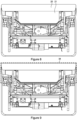
- the vehicle seat as shown in the Figures is an aircraft passenger seat 10.
- the seat 10 comprises a seat base 11 and a backrest portion 12.
- the seat base is sat upon by a user and their back rests upon the backrest portion.
- the seat 10 is a reclining seat 10 which may recline to a substantially fully flat configuration such that the seat base 11 and backrest portion 12 form a generally flat surface for lying upon.
- the backrest portion 12 comprises a support structure 13.
- the support structure 13 retains the backrest in position, supports the weight of a user seated or lying on the seat 10, provides for connection to the seat base 11, and acts to house various systems and ancillary components of the seat 10.
- a user engagable cushioned section 14 is locatable on a user facing side of the support structure 13. The user facing side is that facing a user when said user is seated or lying on the seat 10.
- the cushioned section 14 comprises at least one localised area of increased thickness 15 which provides additional comfort to a user seated upon on the vehicle seat 10, or in the case of a reclining seat lying upon the reclined seat 10.
- the support structure 13 extends between the user facing side thereof 16 to a rear end 17 thereof, the depth of the support structure 13 being defined between the user facing side 16 and the rear end 16.
- the support structure 13 is shaped to define a cavity 18 in the user facing side thereof.
- cavity it is meant that the existing structure is adapted to provide a space or void in the support structure 13.
- the term cavity is intended to be non-limiting in such that the walls of the cavity may comprise gaps or the like.
- the cavity 18 is shaped and dimensioned such that the presence thereof does not increase the depth of the support structure 13, and therefore does not increase the overall depth of the backrest portion 12. This is achieved by forming existing material of the support structure and components thereof around the cavity 18.
- the cavity defines an opening 19 on the user facing side 16 of the support structure 13 such that when a cushioned section 14 is positioned on said user facing side 16 of the support structure at least a portion of the cushioning section may extend into the cavity 18.
- the cushioned section 14 is sized and dimensioned such that at least a portion thereof extends into the cavity 18 of the support structure 13 to form a localised area of increased thickness 15.
- the cushioned section 14 comprises a plurality of cushioned portions 20, 21, at least one cushioned portion 21 being sized and dimensioned such that it extends into the cavity 18 of the support structure to form a localised area of increased thickness 15.
- the formation of a cavity 18 without increasing the depth of the support structure, and placement of at least a portion of the cushioned section 14 therein, allows for increased thickness of cushioning at the location of the cavity 18 providing greater comfort in this area without increasing the overall dimensions of the backrest portion 12.
- This is in contrast to prior art designs wherein all of the cushioning section is located on the user facing side of the backrest portion, or more specifically none of the cushioning is located within the body of the support structure as in the present invention.
- Figures 1 and 2 wherein Figure 1 shows a prior art backrest portion having a straight profile cushioned section and Figure 2 shows a prior art backrest portion having a curved profile cushioned section.
- the straight and curved profiles are depicted by the lines 24 and 25 respectively.
- the entire cushioning layer must be increased in thickness, thus increasing the overall dimensions of the backrest portion, which in a space critical environment such as an aircraft cabin is not desirable. Even if the layer was increased in thickness locally, this thickness increase would increase the thickness of the backrest in this locality.
- the vehicle seat 10 is a reclining vehicle seat 10 such that the backrest portion 12 is movable between a seated configuration and a reclining/sleeping configuration.
- the drawings show only the sleeping configuration, see Figures 3 to 6 in particular.
- the seat base 11 and backrest portion 13 forms a generally flat sleeping surface in sleeping configuration such that a user may adopt a sleeping position.
- the cavity 18 is sized and positioned such that the portion of the cushioned section 21 therein provides additional support to a user when in the sleeping position.
- the positioning of the cavity 18 and associated portion of cushioned section 21 therein is particularly advantageous in supporting a user sleeping on the seat 10 on their side wherein the weight of the user is transferred through one of the users shoulders rather than distributed by the larger surface area of the users back or front when laying on their back or front.
- the positioning of the cavity 18, and cushioning portion 21 that is received thereinto therefore provides for increased thickness in the area of the shoulder of a user when the user is lying on their side, and thus increased comfort to the user.
- the backrest portion 12 comprises a width-wise dimension 22 which extends, in use, generally across the width of the back of a user, and a lengthwise dimension 23 which extends, in use, generally longitudinally along the back of a user.
- the cavity is formed centrally in the support structure 13 with respect to the width-wise dimension 22 and extends only partially along width-wise dimension each side of said width-wise center.
- the cavity 18 extends along the majority of the lengthwise dimension 23 of the backrest portion 12. It should be noted that the dimensions of the cavity 18 and portion 21 of cushioned section therein as shown in the drawings is for illustration only, and represents a preferable arrangement. It should be understood that the cavity 18 and associated portion 21 of cushioned section could take any reasonable size.
- the cushioned section 14 comprises a stepped profile when viewed in cross section in the width-wise dimension.
- the stepped profile comprises a first portion 20 of the cushioned section which extends across the entire width-wise dimension 22 of the backrest portion 12, and a second portion of cushioned section 21, locatable on a support structure facing side 26 of the first portion 20, and centrally in relation to the width-wise dimension of the first portion 20.
- the second portion 21 of cushioned section extends only partially along the width-wise dimension of the backrest portion 12 on each side of the with-wise center of the first portion 20.
- the second portion 21 of cushioned section extends from the first portion 20 of cushioned section, into the cavity 18, and towards the rear end 17 of the support structure 13.
- the second portion 21 of cushioned section may comprise chamfered corners 27 which align with corresponding chamfered interior corners in the cavity 18.
- the top and bottom longitudinal ends 28, 29 of the cavity 18 is a tapered end such that the cavity 18 tapers away from the user facing side of the backrest portion 12.
- the second portion 21 of the cushioned section is correspondingly shaped so as to fit within the tapered cavity 18.
- the cavity 18 extends approximately 303mm in the width-wise dimension and approximately 530mm in the lengthwise dimension.
- the thickness of the second portion 21 of the cushioned section is approximately 100mm. Consequently, the depth of the cavity 18 is approximately 100mm to accommodate the second portion 21 of the cushioned section therein. Overall, when the thickness of the first and second portions 20, 21 of cushioning section are combined, the area of localised thickness provided is approximately 150mm.
- the cushioned section 14 comprises a padded cushion 14 formed from materials as would be typically utilised on aircraft seating.
- the padded cushion 14 may comprise stuffing or padding material within a fabric covering.
- Figures 8 and 9 show a further sectional view showing the cavity and portion 21 of cushioning section located within the cavity.
- the dashed line 34 on Figure 9 is added to highlight that to achieve the additional thickness of padding afforded in the area of the cavity, existing designs would need to increase the cushioning thickness across the entire width of the seat, thus increasing the overall depth of the seat, or requiring significant modification to the support structure to accommodate such a seat width thickness increase.
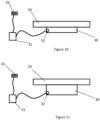
- the cushioning section 14 may further comprise an adjustable cushion section 30, as is best seen in figures 10 and 11 .
- the adjustable cushion section 30 may be selectably inflated or deflated to permit adjustment of the level of cushioning felt by a user.
- Figure 10 illustrates the adjustable cushioning section in a first configuration wherein it is deflated;
- Figure 11 shows the adjustable cushioning section 30 in a second configuration wherein it is inflated.
- Figures 10 and 11 show that the adjustable cushioning section is attached to or in contact with the first portion 20 of the cushioning section, effectively replacing the second portion 21 of the cushioning section.
- the adjustable cushioning section 30 may form a greater or lesser portion of the overall cushioning section 14 as desired, may form part of the first portion 20 of the cushioning section, or may form part of the second portion 21 of the cushioning section.
- the adjustable cushion section 30 may be a pneumatic cushion 30 which is sized and dimensioned such that, when inflated, it expands from the cavity 18 towards the user facing side of the vehicle seat 10.
- the pneumatic cushion is in operable engagement with a pneumatic system comprising an air source 31, an air outlet valve 32, and a user operable control 33 arranged to permit user inflation and deflation of the pneumatic cushion 30 via control of the air source 31 and air outlet valve 32.
- the user operable control 33 may be located in the vehicle seat 10, for example in an arm rest, or may be integrated into a flight entertainment system or the like such that it is operable via a touchscreen thereof.
- the air source 31, air outlet valve 32, and user operable control 33 may be in wired communication, as is shown in Figures 10 and 11 , however in alternative arrangements these components may be in wireless communication via wireless communication methods that would be well known to the skilled person.
- the air source 31 may be an air pump or the like configured to pump air into the pneumatic cushion 30 to inflate the cushion 30 upon a user selecting to inflate said cushion 30 using the user operable control 30.
- the air outlet valve may be opened, by the user selecting to deflate the pneumatic cushion using the user operable control 33, to allow air to exit the pneumatic cushion thus deflating said cushion 30.
- the air source 31 is capable of both forcing air into the pneumatic cushion 30, and operating in a reverse manner such that may apply suction to actively remove air therefrom.
- the air outlet valve may not be required in such an arrangement.
- the pneumatic cushion may be inflated to any intermediate partially inflated configuration between its inflated and deflated configurations, such that a user may obtain optimal comfort levels for their particular needs.
- a method of manufacturing the vehicle seat 10 comprises forming the seat base 11 and the backrest portion 12, the backrest portion comprising the support structure 13.
- a cavity is formed in the support structure for receiving a portion of the cushioned section 14.
- the cushioned section 14 is formed having a localised area of increased thickness 15, and fitted to the backrest portion such that a portion 21 of the cushioned section 14 is locatable in the cavity 18.
Landscapes
- Engineering & Computer Science (AREA)
- Aviation & Aerospace Engineering (AREA)
- Transportation (AREA)
- Mechanical Engineering (AREA)
- Seats For Vehicles (AREA)
Claims (12)
- Fahrzeugsitz (10), eine Sitzfläche (11) und einen Rückenlehnenabschnitt (12) umfassend, wobei der Rückenlehnenabschnitt Folgendes umfasst:eine Stützstruktur (13);einen gepolsterten Bereich (14), der vom Benutzer aktiviert werden kann und an einer Benutzerbetätigungsseite der Stützstruktur angeordnet werden kann;wobei die Stützstruktur (13) so geformt und dimensioniert ist, um zumindest einen Abschnitt des gepolsterten Bereichs (14) aufzunehmen, sodass der gepolsterte Bereich zumindest einen lokal begrenzten Bereich erhöhter Dicke (15) umfasst, dadurch gekennzeichnet, dass die Stützstruktur so geformt ist, um einen Hohlraum (18) zu definieren, wobei der Hohlraum eine Öffnung (19) darin von der dem Benutzer zugewandten Seite der Stützstruktur definiert, und wobei die oberen und/oder unteren Längsenden (28, 29) des Hohlraums verjüngte Enden sind, sodass der Hohlraum (18) sich von der dem Benutzer zugewandten Seite des Rückenlehnenabschnitts (12) weg verjüngt.
- Fahrzeugsitz (10) nach Anspruch 1, wobei der gepolsterte Bereich (14) derart bemessen und dimensioniert ist, dass sich zumindest ein Abschnitt davon in den Hohlraum (18) der Stützstruktur (13) erstreckt, um einen lokalisierten Bereich mit erhöhter Dicke (15) zu bilden, oder wobei der gepolsterte Bereich (14) eine Vielzahl von gepolsterten Abschnitten umfasst, wobei zumindest ein gepolsterter Abschnitt derart bemessen und dimensioniert ist, dass sich zumindest ein Abschnitt davon in den Hohlraum (18) der Stützstruktur (13) erstreckt, um einen lokalisierten Bereich mit erhöhter Dicke zu bilden.
- Fahrzeugsitz (10) nach Anspruch 1 oder Anspruch 2, wobei der Fahrzeugsitz ein verstellbarer Fahrzeugsitz ist, so dass der Rückenlehnenabschnitt (12) zwischen einer Sitzkonfiguration und einer Schlafkonfiguration beweglich ist, wobei die Sitzfläche (11) und der Rückenlehnenabschnitt in der Schlafkonfiguration eine im Allgemeinen flache Schlaffläche bilden, so dass ein Benutzer eine Schlafposition einnehmen kann, und der Hohlraum (18) so bemessen und positioniert ist, dass der Teil des darin befindlichen gepolsterten Bereichs der Schulter eines Benutzers zusätzliche Unterstützung bietet, wenn dieser auf der Seite schläft.
- Fahrzeugsitz (10) nach einem der Ansprüche 1 bis 3, wobei der Rückenlehnenabschnitt (12) eine Breitenabmessung, die sich bei Benutzung im Allgemeinen über die Breite des Rückens eines Benutzers erstreckt, und eine Längsabmessung aufweist, die sich bei Benutzung im Allgemeinen in Längsrichtung entlang des Rückens eines Benutzers erstreckt, wobei der Hohlraum (18) in Bezug auf die Breitenabmessung mittig in der Stützstruktur (13) ausgebildet ist und sich zumindest teilweise entlang der Längsabmessung erstreckt, und vorzugsweise wobei sich der Hohlraum (18) entlang im Wesentlichen der gesamten Längsabmessung des Abschnitts der Rückenlehne (12) erstreckt.
- Fahrzeugsitz (10) nach Anspruch 3 oder Anspruch 4, wobei der gepolsterte Bereich (14) ein Stufenprofil aufweist, wenn er im Querschnitt in der Breitenabmessung betrachtet wird.
- Fahrzeugsitz nach Anspruch 5, wobei das Stufenprofil einen ersten Abschnitt (20) des gepolsterten Bereichs, der sich über die gesamte Breitenausdehnung des Rückenlehnenabschnitts erstreckt, und einen zweiten Abschnitt (21) des gepolsterten Bereichs umfasst, der auf einer der Stützstruktur zugewandten Seite (26) des ersten Abschnitts (20) und mittig in Bezug auf die Breitenausdehnung des ersten Abschnitts angeordnet werden kann und sich nur teilweise entlang der Rückenlehne (12) in der Breitenausdehnung erstreckt.
- Fahrzeugsitz (10) nach Anspruch 5 oder Anspruch 6, wobei sich der Hohlraum (18) ungefähr 250 bis 350 mm in der Breitenabmessung erstreckt, oder wobei sich der Hohlraum (18) ungefähr 500 bis 600 mm in der Längenabmessung erstreckt.
- Fahrzeugsitz (10) nach einem der vorhergehenden Ansprüche, wobei der gepolsterte Bereich (14) ein gepolstertes Kissen umfasst und wobei der gepolsterte Bereich optional ferner einen einstellbaren Polsterbereich (30) umfassen kann, der wahlweise aufgeblasen oder entleert werden kann, um die Einstellung des Dämpfungsniveaus durch einen Benutzer zu ermöglichen.
- Fahrzeugsitz (10) nach Anspruch 8, wobei der verstellbare Polsterbereich (30) ein Luftpolster (30) ist, das so bemessen und dimensioniert ist, dass es sich, wenn es aufgeblasen wird, von dem Hohlraum (18) zu der dem Benutzer zugewandten Seite des Fahrzeugsitzes hin ausdehnt.
- Fahrzeugsitz (10) nach Anspruch 9, wobei das Luftpolster (30) in einem betriebsmäßigen Eingriff mit einem Pneumatiksystem ist, das eine Luftquelle (31), ein Luftauslassventil (32) und eine vom Benutzer bedienbare Steuerung (33) umfasst, die so angeordnet ist, dass ein Aufblasen und Ablassen des Luftpolsters durch den Benutzer über die Steuerung der Luftquelle und des Luftauslassventils ermöglicht wird.
- Fahrzeugsitz (10) nach einem der vorhergehenden Ansprüche, wobei der Fahrzeugsitz (10) ein verstellbarer Fluggastsitz ist.
- Verfahren zum Herstellen eines Fahrzeugsitzes (10), folgende Schritte umfassend:Bereitstellen einer Sitzfläche (11) und eines Rückenlehnenabschnitts (12), wobei der Rückenlehnenabschnitt eine Stützstruktur (13) umfasst, die geformt und dimensioniert ist, um zumindest einen Abschnitt eines Polsterbereichs (14) aufzunehmen;Ausbilden eines Polsterbereichs (14) mit einem örtlich begrenzten Bereich erhöhter Dicke (15); undAnbringen des Polsterbereichs (14) an einer dem Benutzer zugewandten Seite der Stützstruktur (13), sodass zumindest ein Teil des Polsterbereichs (14) von der Stützstruktur aufgenommen wird; unddadurch gekennzeichnet, dass die Stützstruktur (13) geformt ist, um einen Hohlraum (18) zu definieren, wobei der Hohlraum eine Öffnung (19) darin von der dem Benutzer zugewandten Seite der Stützstruktur definiert, und das obere und/oder untere Längsende (28, 29) des Hohlraums derart verjüngt ist, dass der Hohlraum sich von der dem Benutzer zugewandten Seite des Rückenlehnenabschnitts (12) weg verjüngt.
Applications Claiming Priority (1)
| Application Number | Priority Date | Filing Date | Title |
|---|---|---|---|
| GB2111985.4A GB2609984B (en) | 2021-08-20 | 2021-08-20 | A vehicle seat |
Publications (3)
| Publication Number | Publication Date |
|---|---|
| EP4137359A1 EP4137359A1 (de) | 2023-02-22 |
| EP4137359B1 true EP4137359B1 (de) | 2025-05-21 |
| EP4137359C0 EP4137359C0 (de) | 2025-05-21 |
Family
ID=77913986
Family Applications (1)
| Application Number | Title | Priority Date | Filing Date |
|---|---|---|---|
| EP22170533.8A Active EP4137359B1 (de) | 2021-08-20 | 2022-04-28 | Fahrzeugsitz |
Country Status (3)
| Country | Link |
|---|---|
| US (1) | US12179642B2 (de) |
| EP (1) | EP4137359B1 (de) |
| GB (1) | GB2609984B (de) |
Family Cites Families (18)
| Publication number | Priority date | Publication date | Assignee | Title |
|---|---|---|---|---|
| US4589695A (en) * | 1984-03-28 | 1986-05-20 | Tachikawa Spring Co., Ltd. | Vehicle seat |
| DE3607258A1 (de) * | 1986-03-05 | 1987-09-10 | Metzeler Schaum Gmbh | Einstellbare abstuetzung an sitz- und rueckenpolstern |
| JPS6414053U (de) * | 1987-07-15 | 1989-01-24 | ||
| US5092654A (en) * | 1989-03-30 | 1992-03-03 | Aisin Seiki Kabushiki Kaisha | Seatback spring device |
| US5076643A (en) * | 1990-08-20 | 1991-12-31 | Lear Seating Corporation | Lumbar support |
| US5485976A (en) * | 1994-01-12 | 1996-01-23 | Weber Aircraft, Inc. | Plastic bottom diaphragm for aircraft seat |
| US20020060485A1 (en) * | 2000-11-17 | 2002-05-23 | Lear Corporation | Adjustable sport vehicle seat |
| DE10358951B4 (de) * | 2003-12-15 | 2015-02-12 | Deutsche Lufthansa Ag | Luftkissenanordnung für einen Passagiersitz |
| US20100207443A1 (en) * | 2009-02-19 | 2010-08-19 | Faurecia Automotive Seating, Inc. | Vehicle seat cushion with inflatable air bladder |
| US8162398B2 (en) * | 2009-03-26 | 2012-04-24 | Schukra of North America Co. | Zone lumbar massage system |
| JP5584503B2 (ja) * | 2010-03-26 | 2014-09-03 | テイ・エス テック株式会社 | 乗物用シート |
| EP3197777B1 (de) * | 2014-09-24 | 2021-06-02 | B/E Aerospace, Inc. | Sitzschalenanordnung mit eingebauter komfortfeder |
| US10118704B2 (en) * | 2015-04-10 | 2018-11-06 | Franklin Products, Inc. | Hybrid seat pan and diaphragm |
| US9937826B2 (en) * | 2015-09-03 | 2018-04-10 | Ford Global Technologies, Llc | Bladder system for vehicle seating assembly |
| DE102015116593A1 (de) * | 2015-09-30 | 2017-03-30 | Recaro Aircraft Seating Gmbh & Co. Kg | Sitzvorrichtung |
| GB2550191A (en) * | 2016-05-12 | 2017-11-15 | Gordon Murray Design Ltd | Vehicle seat |
| CA3013671C (en) * | 2016-10-19 | 2023-01-24 | B/E Aerospace, Inc. | Passenger seat having side sleep support assembly |
| US10486565B2 (en) * | 2017-05-09 | 2019-11-26 | Lear Corporation | Dual firmness foam flex point elimination |
-
2021
- 2021-08-20 GB GB2111985.4A patent/GB2609984B/en active Active
-
2022
- 2022-04-28 EP EP22170533.8A patent/EP4137359B1/de active Active
- 2022-07-25 US US17/872,216 patent/US12179642B2/en active Active
Also Published As
| Publication number | Publication date |
|---|---|
| US20230056162A1 (en) | 2023-02-23 |
| US12179642B2 (en) | 2024-12-31 |
| EP4137359A1 (de) | 2023-02-22 |
| GB2609984B (en) | 2024-05-29 |
| EP4137359C0 (de) | 2025-05-21 |
| GB2609984A (en) | 2023-02-22 |
| GB202111985D0 (en) | 2021-10-06 |
Similar Documents
| Publication | Publication Date | Title |
|---|---|---|
| US5628547A (en) | Passenger seat | |
| JP4589300B2 (ja) | 特には航空機又は自動車等の座席 | |
| CN106494279B (zh) | 用于车辆座椅总成的气囊系统 | |
| US10829019B2 (en) | Headrest for a vehicle seat | |
| EP3575144A1 (de) | Dynamisches pneumatisches stützsystem | |
| US6659552B2 (en) | Inflatable aircraft seat cushion | |
| US20040174056A1 (en) | Inflatable seat cushion | |
| US20050179294A1 (en) | Passenger seat with tilting seat bottom | |
| EP3512771B1 (de) | Flugzeugsitz | |
| CN108608901A (zh) | 可充气的支撑囊组件 | |
| CN112477716A (zh) | 一种具有自适应调节功能的汽车座椅及其控制方法 | |
| JP2008544927A (ja) | 運輸座席の配置 | |
| EP3529154B1 (de) | Fahrgastsitz mit seitlicher schlafstützanordnung | |
| CN101454203A (zh) | 交通工具座椅组件 | |
| US8157321B2 (en) | Cushion presenter system | |
| US5975636A (en) | Assembly for filling void between cushions of reclining seats | |
| US10604046B2 (en) | Occupant support device for a seat | |
| EP4137359B1 (de) | Fahrzeugsitz | |
| KR102716318B1 (ko) | 차량용 릴렉션 시트 프레임 시스템 | |
| EP1714583B1 (de) | Sitz mit einem aufblasbaren Sitzteil | |
| CN119176066A (zh) | 车辆座椅、机动车和用于运行车辆座椅的方法 | |
| WO1996014783A1 (en) | Self-inflating modular seat insert | |
| CN215204561U (zh) | 一种具有自适应调节功能的汽车座椅 | |
| JP2007514479A (ja) | パッセンジャシートのためのエアクッション装置 | |
| CN117203091A (zh) | 气动气囊装置 |
Legal Events
| Date | Code | Title | Description |
|---|---|---|---|
| PUAI | Public reference made under article 153(3) epc to a published international application that has entered the european phase |
Free format text: ORIGINAL CODE: 0009012 |
|
| STAA | Information on the status of an ep patent application or granted ep patent |
Free format text: STATUS: THE APPLICATION HAS BEEN PUBLISHED |
|
| AK | Designated contracting states |
Kind code of ref document: A1 Designated state(s): AL AT BE BG CH CY CZ DE DK EE ES FI FR GB GR HR HU IE IS IT LI LT LU LV MC MK MT NL NO PL PT RO RS SE SI SK SM TR |
|
| STAA | Information on the status of an ep patent application or granted ep patent |
Free format text: STATUS: REQUEST FOR EXAMINATION WAS MADE |
|
| 17P | Request for examination filed |
Effective date: 20230821 |
|
| RBV | Designated contracting states (corrected) |
Designated state(s): AL AT BE BG CH CY CZ DE DK EE ES FI FR GB GR HR HU IE IS IT LI LT LU LV MC MK MT NL NO PL PT RO RS SE SI SK SM TR |
|
| RIC1 | Information provided on ipc code assigned before grant |
Ipc: B60N 2/64 20060101ALI20240916BHEP Ipc: B60N 2/34 20060101AFI20240916BHEP |
|
| GRAP | Despatch of communication of intention to grant a patent |
Free format text: ORIGINAL CODE: EPIDOSNIGR1 |
|
| STAA | Information on the status of an ep patent application or granted ep patent |
Free format text: STATUS: GRANT OF PATENT IS INTENDED |
|
| INTG | Intention to grant announced |
Effective date: 20241204 |
|
| GRAS | Grant fee paid |
Free format text: ORIGINAL CODE: EPIDOSNIGR3 |
|
| GRAA | (expected) grant |
Free format text: ORIGINAL CODE: 0009210 |
|
| STAA | Information on the status of an ep patent application or granted ep patent |
Free format text: STATUS: THE PATENT HAS BEEN GRANTED |
|
| RBV | Designated contracting states (corrected) |
Designated state(s): AL AT BE BG CH CY CZ DE DK EE ES FI FR GR HR HU IE IS IT LI LT LU LV MC MK MT NL NO PL PT RO RS SE SI SK SM TR |
|
| AK | Designated contracting states |
Kind code of ref document: B1 Designated state(s): AL AT BE BG CH CY CZ DE DK EE ES FI FR GR HR HU IE IS IT LI LT LU LV MC MK MT NL NO PL PT RO RS SE SI SK SM TR |
|
| REG | Reference to a national code |
Ref country code: CH Ref legal event code: EP |
|
| REG | Reference to a national code |
Ref country code: DE Ref legal event code: R096 Ref document number: 602022014841 Country of ref document: DE |
|
| REG | Reference to a national code |
Ref country code: IE Ref legal event code: FG4D |
|
| U01 | Request for unitary effect filed |
Effective date: 20250618 |
|
| U07 | Unitary effect registered |
Designated state(s): AT BE BG DE DK EE FI FR IT LT LU LV MT NL PT RO SE SI Effective date: 20250627 |
|
| PG25 | Lapsed in a contracting state [announced via postgrant information from national office to epo] |
Ref country code: ES Free format text: LAPSE BECAUSE OF FAILURE TO SUBMIT A TRANSLATION OF THE DESCRIPTION OR TO PAY THE FEE WITHIN THE PRESCRIBED TIME-LIMIT Effective date: 20250521 |
|
| PG25 | Lapsed in a contracting state [announced via postgrant information from national office to epo] |
Ref country code: NO Free format text: LAPSE BECAUSE OF FAILURE TO SUBMIT A TRANSLATION OF THE DESCRIPTION OR TO PAY THE FEE WITHIN THE PRESCRIBED TIME-LIMIT Effective date: 20250821 Ref country code: GR Free format text: LAPSE BECAUSE OF FAILURE TO SUBMIT A TRANSLATION OF THE DESCRIPTION OR TO PAY THE FEE WITHIN THE PRESCRIBED TIME-LIMIT Effective date: 20250822 |
|
| PG25 | Lapsed in a contracting state [announced via postgrant information from national office to epo] |
Ref country code: PL Free format text: LAPSE BECAUSE OF FAILURE TO SUBMIT A TRANSLATION OF THE DESCRIPTION OR TO PAY THE FEE WITHIN THE PRESCRIBED TIME-LIMIT Effective date: 20250521 |
|
| PG25 | Lapsed in a contracting state [announced via postgrant information from national office to epo] |
Ref country code: HR Free format text: LAPSE BECAUSE OF FAILURE TO SUBMIT A TRANSLATION OF THE DESCRIPTION OR TO PAY THE FEE WITHIN THE PRESCRIBED TIME-LIMIT Effective date: 20250521 |
|
| PG25 | Lapsed in a contracting state [announced via postgrant information from national office to epo] |
Ref country code: RS Free format text: LAPSE BECAUSE OF FAILURE TO SUBMIT A TRANSLATION OF THE DESCRIPTION OR TO PAY THE FEE WITHIN THE PRESCRIBED TIME-LIMIT Effective date: 20250821 |
|
| PG25 | Lapsed in a contracting state [announced via postgrant information from national office to epo] |
Ref country code: IS Free format text: LAPSE BECAUSE OF FAILURE TO SUBMIT A TRANSLATION OF THE DESCRIPTION OR TO PAY THE FEE WITHIN THE PRESCRIBED TIME-LIMIT Effective date: 20250921 |
|
| PG25 | Lapsed in a contracting state [announced via postgrant information from national office to epo] |
Ref country code: SM Free format text: LAPSE BECAUSE OF FAILURE TO SUBMIT A TRANSLATION OF THE DESCRIPTION OR TO PAY THE FEE WITHIN THE PRESCRIBED TIME-LIMIT Effective date: 20250521 |
|
| PG25 | Lapsed in a contracting state [announced via postgrant information from national office to epo] |
Ref country code: CZ Free format text: LAPSE BECAUSE OF FAILURE TO SUBMIT A TRANSLATION OF THE DESCRIPTION OR TO PAY THE FEE WITHIN THE PRESCRIBED TIME-LIMIT Effective date: 20250521 |
|
| PG25 | Lapsed in a contracting state [announced via postgrant information from national office to epo] |
Ref country code: SK Free format text: LAPSE BECAUSE OF FAILURE TO SUBMIT A TRANSLATION OF THE DESCRIPTION OR TO PAY THE FEE WITHIN THE PRESCRIBED TIME-LIMIT Effective date: 20250521 |