EP4137259B1 - Laminatformverfahren - Google Patents
Laminatformverfahren Download PDFInfo
- Publication number
- EP4137259B1 EP4137259B1 EP21808495.2A EP21808495A EP4137259B1 EP 4137259 B1 EP4137259 B1 EP 4137259B1 EP 21808495 A EP21808495 A EP 21808495A EP 4137259 B1 EP4137259 B1 EP 4137259B1
- Authority
- EP
- European Patent Office
- Prior art keywords
- weld bead
- shape
- bead
- cross
- welding
- Prior art date
- Legal status (The legal status is an assumption and is not a legal conclusion. Google has not performed a legal analysis and makes no representation as to the accuracy of the status listed.)
- Active
Links
Images





Classifications
-
- B—PERFORMING OPERATIONS; TRANSPORTING
- B29—WORKING OF PLASTICS; WORKING OF SUBSTANCES IN A PLASTIC STATE IN GENERAL
- B29C—SHAPING OR JOINING OF PLASTICS; SHAPING OF MATERIAL IN A PLASTIC STATE, NOT OTHERWISE PROVIDED FOR; AFTER-TREATMENT OF THE SHAPED PRODUCTS, e.g. REPAIRING
- B29C64/00—Additive manufacturing, i.e. manufacturing of three-dimensional [3D] objects by additive deposition, additive agglomeration or additive layering, e.g. by 3D printing, stereolithography or selective laser sintering
- B29C64/10—Processes of additive manufacturing
- B29C64/106—Processes of additive manufacturing using only liquids or viscous materials, e.g. depositing a continuous bead of viscous material
- B29C64/118—Processes of additive manufacturing using only liquids or viscous materials, e.g. depositing a continuous bead of viscous material using filamentary material being melted, e.g. fused deposition modelling [FDM]
-
- B—PERFORMING OPERATIONS; TRANSPORTING
- B23—MACHINE TOOLS; METAL-WORKING NOT OTHERWISE PROVIDED FOR
- B23K—SOLDERING OR UNSOLDERING; WELDING; CLADDING OR PLATING BY SOLDERING OR WELDING; CUTTING BY APPLYING HEAT LOCALLY, e.g. FLAME CUTTING; WORKING BY LASER BEAM
- B23K9/00—Arc welding or cutting
- B23K9/02—Seam welding; Backing means; Inserts
- B23K9/032—Seam welding; Backing means; Inserts for three-dimensional [3D] seams
-
- B—PERFORMING OPERATIONS; TRANSPORTING
- B23—MACHINE TOOLS; METAL-WORKING NOT OTHERWISE PROVIDED FOR
- B23K—SOLDERING OR UNSOLDERING; WELDING; CLADDING OR PLATING BY SOLDERING OR WELDING; CUTTING BY APPLYING HEAT LOCALLY, e.g. FLAME CUTTING; WORKING BY LASER BEAM
- B23K9/00—Arc welding or cutting
- B23K9/04—Welding for other purposes than joining, e.g. built-up welding
-
- B—PERFORMING OPERATIONS; TRANSPORTING
- B23—MACHINE TOOLS; METAL-WORKING NOT OTHERWISE PROVIDED FOR
- B23K—SOLDERING OR UNSOLDERING; WELDING; CLADDING OR PLATING BY SOLDERING OR WELDING; CUTTING BY APPLYING HEAT LOCALLY, e.g. FLAME CUTTING; WORKING BY LASER BEAM
- B23K9/00—Arc welding or cutting
- B23K9/095—Monitoring or automatic control of welding parameters
- B23K9/0953—Monitoring or automatic control of welding parameters using computing means
-
- B—PERFORMING OPERATIONS; TRANSPORTING
- B23—MACHINE TOOLS; METAL-WORKING NOT OTHERWISE PROVIDED FOR
- B23K—SOLDERING OR UNSOLDERING; WELDING; CLADDING OR PLATING BY SOLDERING OR WELDING; CUTTING BY APPLYING HEAT LOCALLY, e.g. FLAME CUTTING; WORKING BY LASER BEAM
- B23K9/00—Arc welding or cutting
- B23K9/095—Monitoring or automatic control of welding parameters
- B23K9/0956—Monitoring or automatic control of welding parameters using sensing means, e.g. optical
-
- B—PERFORMING OPERATIONS; TRANSPORTING
- B29—WORKING OF PLASTICS; WORKING OF SUBSTANCES IN A PLASTIC STATE IN GENERAL
- B29C—SHAPING OR JOINING OF PLASTICS; SHAPING OF MATERIAL IN A PLASTIC STATE, NOT OTHERWISE PROVIDED FOR; AFTER-TREATMENT OF THE SHAPED PRODUCTS, e.g. REPAIRING
- B29C64/00—Additive manufacturing, i.e. manufacturing of three-dimensional [3D] objects by additive deposition, additive agglomeration or additive layering, e.g. by 3D printing, stereolithography or selective laser sintering
- B29C64/30—Auxiliary operations or equipment
- B29C64/386—Data acquisition or data processing for additive manufacturing
- B29C64/393—Data acquisition or data processing for additive manufacturing for controlling or regulating additive manufacturing processes
-
- B—PERFORMING OPERATIONS; TRANSPORTING
- B33—ADDITIVE MANUFACTURING TECHNOLOGY
- B33Y—ADDITIVE MANUFACTURING, i.e. MANUFACTURING OF THREE-DIMENSIONAL [3D] OBJECTS BY ADDITIVE DEPOSITION, ADDITIVE AGGLOMERATION OR ADDITIVE LAYERING, e.g. BY 3D PRINTING, STEREOLITHOGRAPHY OR SELECTIVE LASER SINTERING
- B33Y10/00—Processes of additive manufacturing
-
- B—PERFORMING OPERATIONS; TRANSPORTING
- B33—ADDITIVE MANUFACTURING TECHNOLOGY
- B33Y—ADDITIVE MANUFACTURING, i.e. MANUFACTURING OF THREE-DIMENSIONAL [3D] OBJECTS BY ADDITIVE DEPOSITION, ADDITIVE AGGLOMERATION OR ADDITIVE LAYERING, e.g. BY 3D PRINTING, STEREOLITHOGRAPHY OR SELECTIVE LASER SINTERING
- B33Y50/00—Data acquisition or data processing for additive manufacturing
- B33Y50/02—Data acquisition or data processing for additive manufacturing for controlling or regulating additive manufacturing processes
-
- Y—GENERAL TAGGING OF NEW TECHNOLOGICAL DEVELOPMENTS; GENERAL TAGGING OF CROSS-SECTIONAL TECHNOLOGIES SPANNING OVER SEVERAL SECTIONS OF THE IPC; TECHNICAL SUBJECTS COVERED BY FORMER USPC CROSS-REFERENCE ART COLLECTIONS [XRACs] AND DIGESTS
- Y02—TECHNOLOGIES OR APPLICATIONS FOR MITIGATION OR ADAPTATION AGAINST CLIMATE CHANGE
- Y02P—CLIMATE CHANGE MITIGATION TECHNOLOGIES IN THE PRODUCTION OR PROCESSING OF GOODS
- Y02P10/00—Technologies related to metal processing
- Y02P10/25—Process efficiency
Definitions
- the present invention relates to an additive manufacturing method.
- Patent Literatures 1 and 2 A technique of controlling a welding robot to manufacture an additively-manufactured object constituted by a multi-layered weld bead is developed (see, for example, Patent Literatures 1 and 2 and Non-patent Literature 1).
- Patent Literature 1 describes a method of adjusting a target position, a welding current, a welding voltage, and the like of a welding torch when welding iron poles for construction, by measuring a shape of a welded weld bead in real time with a laser sensor and selecting welding conditions from a database according to the measured bead shape.
- Non-patent Literature 1 describes a method of adjusting a height and a width of a weld bead to be formed in additive manufacturing with molten wires, by controlling a welding voltage and a welding speed according to a bead shape measured by a laser sensor.
- Patent Literature 2 describes a method for adjusting a target position for next bead formation in multi-layer welding.
- a shape of a weld bead formed on a flat plate is measured, and a bead shape approximation function is obtained from the measurement result.
- a bead shape prediction function of a weld bead formed when there is an inclined wall plate on both sides of the bead is obtained using this bead shape approximation function.
- the target position for the bead formation is set to either a position of a minimum bead height or a position of an intersection of the bead and the inclined wall plate according to the obtained bead shape prediction function.
- US 2019/134732 A1 discloses a metal laminating and molding method, wherein a 3-dimensional molded object is formed by sequentially laminating a plurality of metal layers.
- the metal laminating and molding method is accomplished by repeatedly performing a unit process including a metal layer laminating process of laminating the metal layer constituted by welding beads formed through arc welding and a removal process of removing impurities from a surface of the metal layer laminated in the metal layer laminating process.
- the metal layer laminating process is performed again such that a new metal layer is laminated on the surface of the metal layer from which impurities have been removed in the removal process.
- Non-patent Literature 1 Han Q., Li Y, Zhang G. (2016) Online Control of Deposited Geometry of Multi-layer Multi-bead Structure for Wire and Arc Additive Manufacturing. In: Chen S., Zhang Y, Feng Z. (eds) Transactions on Intelligent Welding Manufacturing. Transactions on Intelligent Welding Manufacturing. Springer, Singapore
- Patent Literature 1 and Non-patent Literature 1 when measuring the shape of the formed weld bead and then performing feedback control of the bead formation position, welding conditions, and the like in the next step, in order to shorten a tact time of the step, the measurement is required to be in real time and in a high speed.
- variation in detected values is generally large due to light receiving sensitivity of the sensor, linearity of the bead, and the like. Therefore, it takes time to perform stable measurement, and it is difficult to speed up the measurement.
- a groove can be used in normal groove welding to enable highly accurate positioning.
- there is no absolute positioning reference such as a groove. Therefore, the bead shape approximation function cannot be obtained based on the position of the inclined side plate arranged on both sides of the bead as in Patent Literature 2.
- the approximation calculation of the bead shape becomes complicated, approximation accuracy is lowered, and accuracy of the predicted bead shape is lowered.
- the formed weld bead changes depending on conditions such as a protrusion length of a welding wire (filler metal) that protrudes from a tip of the torch, and a close distance to a surrounding bead, the target position for the bead formation may be displaced, or welding may become unstable due to adhesion of spatter.
- a welding wire iller metal
- an object of the present invention is to provide an additive manufacturing method capable of accurately obtaining the target position for the bead formation and manufacturing an additively-manufactured object with high accuracy.
- an additive manufacturing method of depositing weld beads formed by melting and solidifying a filler metal while moving a welding torch attached to a robot tip shaft is defined in claim 1, the additive manufacturing method including:
- the target position for the bead formation can be obtained correctly, and the additively-manufactured object can be manufactured with high accuracy.
- Fig. 1 is a configuration diagram of an additively-manufactured object manufacturing device.
- the manufacturing device 11 includes a welding robot 19 including a tip shaft provided with a welding torch 17, and a filler metal supply unit 21 that supplies a filler metal (welding wire) M to the welding torch 17.
- the manufacturing device 11 forms a weld bead B while the welding robot driving the welding torch 17 to move.
- the tip shaft of the welding robot 19 is provided with a non-contact shape sensor that moves integrally with the welding torch 17.
- a non-contact shape sensor a laser shape sensor 23 that detects a three-dimensional shape by a light section method, a pattern projection method, or the like is used here, but the detection method is not limited.
- the welding robot 19 is a multi-joint robot, and the welding torch 17 attached to the tip shaft of a robot arm is supported so that the filler metal M can be continuously supplied.
- a position and a posture of the welding torch 17 can be freely set three-dimensionally within a range of degrees of freedom of the robot arm.
- the welding torch 17 includes a shield nozzle (not shown), and a shield gas is supplied from the shield nozzle.
- An arc welding method may be a consumable electrode type such as shielded metal arc welding or carbon dioxide gas arc welding, or a non-consumable electrode type such as TIG welding or plasma arc welding, and is appropriately selected according to the additively-manufactured object to be produced.
- a contact tip is disposed inside the shield nozzle, and the contact tip holds the filler metal M to which a melting current is supplied.
- the welding torch 17 holds the filler metal M and generates an arc from a tip of the filler metal M in a shield gas atmosphere.
- the filler metal M is fed from the filler metal supply unit 21 to the welding torch 17 by a feeding mechanism (not shown) attached to the robot arm or the like.
- the linear weld bead B which is a melted and solidified body of the filler metal M, is formed on a base portion 25.
- the base portion 25 is made of a metal plate such as a steel plate, and is basically larger than a bottom surface (lowermost layer surface) of an additively-manufactured object W. Note that the base portion 25 is not limited to have a plate-like shape, and may be a block-like, bar-like, columnar-like, or other shape base.
- any commercially available welding wire can be used.
- a wire specified by solid wires for MAG and MIG welding of mild steel, high strength steel and low temperature service steel (JISZ 3312), flux cored wires for arc welding of mild steel, high strength steel and low temperature service steel (JISZ 3313), or the like can be used.
- the controller 13 includes a CAD/CAM unit 31, a track calculation unit 33, a storage unit 35, and a control unit 37 connected to the CAD/CAM unit 31, the track calculation unit 33, and the storage unit 35.
- the CAD/CAM unit 31 receives shape data (CAD data and the like) of the additively-manufactured object to be produced, and creates a deposition track plan indicating a procedure for manufacturing the additively-manufactured object in cooperation with the track calculation unit 33.
- This deposition track plan is analytically obtained based on various conditions such as shape, material, and heat input from the input shape data and based on an appropriate algorithm so that deposition can be efficiently performed.
- the shape data is divided into a plurality of layers to generate layer shape data indicating a shape of each layer. Then, a movement track and welding conditions of the welding torch 17 are determined according to the generated layer shape data, and a driving program for the welding robot 19 and the power supply device 15 for forming the weld bead B is generated.
- This driving program implements operations corresponding to the deposition track plan.
- Various data such as the driving program and the welding conditions are stored in the storage unit 35.
- the control unit 37 drives the welding robot 19, the power supply device 15, and the like by executing the driving program stored in the storage unit 35, thereby forming the weld bead B. That is, the control unit 37 drives the welding robot 19 to move the welding torch 17 along the set track of the welding torch 17, and forms the weld bead B by melting the filler metal M protruding from a tip of the welding torch 17 with an arc according to the set welding conditions. Then, a plurality of weld beads B are formed on the base portion 25 to be adjacent to each other to form a weld bead layer 27, and deposition of a next layer of the welding bead layer 27 on this welding bead layer 27 is repeated. In this way, the additively-manufactured object W having a desired shape is manufactured.
- the laser shape sensor 23 measures a shape of the existing weld bead B that is already formed.
- the measurement by the laser shape sensor 23 may be performed at times other than the welding.
- the track calculation unit 33 obtains a target position of the welding torch 17 for forming the weld bead to be formed next (hereinafter referred to as a torch target position) and welding conditions according to the created deposition track plan and the welding conditions, and a shape measurement result of the existing weld bead during deposition, and changes the deposition track plan and the welding conditions as necessary.
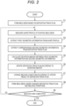
- Fig. 2 is a flow chart showing a procedure for determining the torch target position and the welding conditions for the bead formation from the deposition track plan, the welding conditions, and the shape measurement result of the weld bead.
- the weld bead is formed according to the deposition track plan created based on the inputted shape data (S 1).
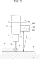
- Fig. 3 is a schematic diagram showing a state of forming the weld bead B.
- the welding robot 19 is driven to form the weld bead B while moving the welding torch 17.
- the laser shape sensor 23 provided integrally with the welding torch 17 at the tip shaft of the welding robot 19 measures the shape of the existing weld bead B at a position downstream of a torch target position P in a welding direction WD.
- the laser shape sensor 23 includes a laser emitting unit 23A and a detection sensor 23B.
- a slit light L1 is emitted from the laser emitting unit 23A, and a reflected light L2 from the existing weld bead B is detected by the detection sensor 23B, which is an image sensor.
- a two-dimensional image detected by the detection sensor 23B includes a pattern corresponding to a height of the weld bead, and the shape of the weld bead is obtained from the pattern. Since the specific shape detection method is publicly known, description thereof is omitted here.
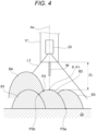
- Fig. 4 is a schematic explanatory diagram showing a cross-sectional shape of the weld bead B and a position of the welding torch 17 when a welding position is viewed from a downstream side in the welding direction.
- lower-layer weld beads B1, B2, and B3 and a weld bead B4 formed above the weld bead B1 are provided around the torch target position P where the weld bead is formed.
- the laser shape sensor 23 emits the slit light L1 and detects reflected light from the weld beads B1 to B4 to obtain a shape of each weld bead around a tip of the torch.
- shape information including an apex P1 of the weld bead B2 located directly below an axis Ax of the welding torch 17, and a narrow point P2 connected to a surface of the weld bead B4 disposed on a side of the welding torch 17 and a surface of the weld bead B2, is obtained.
- Fig. 5 is a schematic explanatory diagram showing a state of forming a new weld bead along the existing weld beads shown in Fig. 4 .
- a torch target position of a weld bead B5 to be formed next shown in Fig. 5 welding conditions during the bead formation, and the like are determined. If there is a difference between setting contents such as the determined torch target position and the welding conditions and setting contents such as the torch movement track in the initial deposition track plan and the welding conditions, the deposition track plan and the welding conditions are changed.
- Fig. 6 is an explanatory diagram showing a basic change procedure in stages (A) to (C) for changing the deposition track plan and the welding conditions for forming the new weld bead according to the shape of the existing weld bead. Note that (A) to (C) of Fig. 6 show the shape in a cross section perpendicular to a longitudinal direction of the weld bead.
- the laser shape sensor 23 measures a shape profile Pf of the existing weld bead (S2).
- a shape profile Pf of the existing weld bead (S2).
- the shape profile Pf may be a straight line or a curved line interpolated between the measurement points, or the like.
- the torch target position P corresponding to the measured weld bead is extracted.
- First geometric information of the bead shape is extracted from the measured shape profile Pf and information on the extracted torch target position P (S3).
- the first geometric information means information including the shape profile Pf and the torch target position P, which are expressed in the same coordinate system by coordinate transformation of the shape profile Pf of the weld bead expressed in a sensor coordinate system by the laser shape sensor 23, and the torch target position P expressed in a robot coordinate system of the welding robot 19 (see Fig. 1 ).
- a welding position is obtained in consideration of inclination (posture) of the welding torch 17 at a torch tip position on the robot coordinate system of the welding robot. That is, a set value of a distance ⁇ L (see Fig. 4 ) from the tip of the torch to the existing weld bead directly below is offset to the torch tip position.
- the offset position is the welding position of the welding torch 17, and this position is defined as the torch target position P.
- the torch target position P in the robot coordinate system is coordinate-transformed into the sensor coordinate system. In this way, the shape profile Pf of the sensor coordinate system and the torch target position P are associated with each other in the same coordinate system.
- second geometric information corresponding to the extracted first geometric information is extracted (S4).
- the second geometric information is information on a target shape of the weld bead and the torch target position in the deposition track plan used when forming the weld bead whose bead shape is measured as described above.
- FIG. 6 shows a target shape Ts of the weld bead and the torch target position P defined by the deposition track plan when forming the weld bead having the shape profile Pf shown in (A) of Fig. 6 .
- the first geometric information and the second geometric information are compared with each other to calculate a deviation amount between the two (S5). That is, a deviation amount between the measured shape of the weld bead and the target shape is obtained.
- (C) of Fig. 6 shows a deviation amount ⁇ H in height between the shape profile Pf shown in (A) of Fig. 6 and the target shape Ts shown in (B) of Fig. 6 .
- the deviation amount ⁇ H is a height difference between an apex of the shape profile Pf and an apex of the target shape Ts, and the apex of the shape profile Pf is determined using a height of a measurement point near the apex.
- the shape profile Pf and the target shape Ts here are arranged so that each torch target position P is at the same position.
- the deposition track plan is updated by changing at least one of a bead height Bh and a bead width Bw (see Fig. 7 ) in the target shape Ts of the weld bead B defined by the deposition track plan so that the deviation amount ⁇ H in height is reduced (S6).
- the deposition track plan may be updated by changing various parameters such as the torch target position and a bead cross-sectional area, in addition to changing the bead height Bh and the bead width Bw.
- the welding conditions are changed according to an update result of the deposition track plan (S7).
- the welding conditions include a position of the welding torch, a posture of the welding torch, a welding speed, a welding voltage, a welding current, and a feeding speed of the filler metal. At least one of these conditions is changed, or a combination of any two or more is changed.
- Fig. 7 is a cross-sectional diagram showing the shape of the weld bead.
- the first geometric information and the second geometric information described above include at least one of the bead height Bh, the bead width Bw, a bead cross-sectional area A in the cross section perpendicular to the bead longitudinal direction, a geometric feature point near the torch target position, and a cross-sectional shape approximation curve indicating a bead outer shape of the weld bead B, whose details will be described later.
- the geometric feature point is a feature point extracted from the existing weld bead disposed around the welding torch 17, as shown in Fig. 4 , and includes the apex P1 of a convex shape of the existing weld bead B2 and the narrow point P2 formed by recessing a bead outer surface inward between the weld bead B2 and another weld bead B4 adj acent to the weld bead B2.
- the geometric feature point Before formation of the weld bead B3, between a pair of points P3a and P3b at widthwise end portions of the weld bead B2, the geometric feature point also includes the point P3a that intersects with a lower layer surface (here, the base portion 25) on which the welding bead B2 is formed.
- a cross-sectional area of a weld bead for the existing weld bead can also be determined by the welding conditions during the bead formation.
- the bead cross-sectional area A is equal to a cross-sectional area of a newly introduced metal material for the bead formation.
- the cross-sectional area referred to here means a volume per unit length of the weld bead, and is represented by the following Formula (1).
- A dw 2 Fw ⁇ / 4 F
- a cross-sectional area of the weld bead to be formed next may be obtained by, for example, using an arc centered at the torch target position P as an outline of the weld bead and using an area inside the arc as the cross-sectional area of the weld bead.
- a method for calculating the cross-sectional area is not limited to this.
- the deposition track plan is updated according to the difference in bead height between the deposition track plan and an actual weld bead formation result, and the welding conditions are changed accordingly, so that it is possible to form the next weld bead with high accuracy. Since the weld bead is formed according to the deposition track plan based on feedback of the actual bead formation result, it is possible to stably implementing manufacturing with an accuracy of an order of 0.1 mm, for example.
- Fig. 8 is an explanatory diagram showing a first change procedure in stages (A) to (C) for changing the deposition track plan and the welding conditions for forming the new weld bead according to the shape of the existing weld bead.
- a cross-sectional area of the shape profile Pf in the cross section perpendicular to the longitudinal direction of the weld bead shown in (A) of Fig. 8 is set as Apf, and a cross-sectional area of the target shape Ts of the weld bead defined by the deposition track plan shown in (B) of Fig. 8 is set as Ats.
- a cross-sectional shape approximation curve Cpf is obtained by approximating the shape profile to a curve model by regression calculation.
- Any curve such as a parabola, a cubic or higher function, and a spline curve can be used as the curve model.
- a curve model of Z aY 2 + bY +c (a, b, and c are coefficients) is used to perform fitting with the measured shape profile Pf (Yj, Zj).
- a publicly known method such as a method of least squares or a method of steepest descent can be adopted.
- the bead shape can be recognized more precisely, and a bead center position, the bead height, and the like of the shape profile can be obtained more accurately. Therefore, the weld bead to be formed next can be formed with higher accuracy.
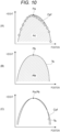
- Fig. 10 is an explanatory diagram showing a third change procedure in stages (A) to (C) for changing the deposition track plan and the welding conditions for forming the new weld bead according to the shape of the existing weld bead.
- the cross-sectional shape approximation curve Cpf obtained by approximating the shape profile to the curve model by regression calculation is set so that a cross-sectional area Ac of a region surrounded by the cross-sectional shape approximation curve Cpf becomes equal to the cross-sectional area Ats of the target shape Ts shown in (B) of Fig. 10 .
- a constrained least squares method can be adopted for this calculation.
- the deposition track plan is changed so that a topmost portion Pa of the cross-sectional shape approximation curve Cpf in which the cross-sectional area Ac is equal to the cross-sectional area Ats coincides with the target formation position of the weld bead, which is a topmost portion Pb of the target shape Ts.
- the target formation position of the weld bead is corrected so that the topmost portion Pa of the cross-sectional shape approximation curve corresponding to the formed weld bead coincides with the topmost portion Pb of the target shape Ts.
- the welding conditions are changed as necessary.
- the weld bead to be formed next can be formed with high accuracy by a simple process of matching the topmost portion Pa of the cross-sectional shape approximation curve with the topmost portion Pb of the target shape Ts.
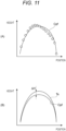
- Fig. 11 is an explanatory diagram showing a fourth change procedure in stages (A) and (B) for changing the deposition track plan and the welding conditions for forming the new weld bead according to the shape of the existing weld bead.
- the target formation position of the weld bead is corrected so that the deviation amount ⁇ H, which is the difference between a height of an optional point on the cross-sectional shape approximation curve Cpf over the entire cross-sectional shape approximation curve Cpf and a height of an outline of the target shape Ts corresponding to the optional point, is reduced.
- the welding conditions are changed as necessary.
- the correction can be performed more stably and accurately than when the deviation amount ⁇ H is determined using the shape profile shown in Fig. 6 , and the weld bead can be formed with higher accuracy.
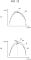
- Fig. 12 is an explanatory diagram showing a fifth change procedure in stages (A) and (B) for changing the deposition track plan and the welding conditions for forming the new weld bead according to the shape of the existing weld bead.
- the deposition track plan is changed so that the position of the cross-sectional shape approximation curve Cpf matches the target formation position of the weld bead, which is the target shape Ts. That is, the deposition track plan is changed so as to match the topmost portion Pa of the cross-sectional shape approximation curve corresponding to the formed weld bead with the topmost portion Pb of the target shape Ts. Then, according to the updated deposition track plan, the welding conditions are changed as necessary.
- the deviation amount ⁇ H in the bead height is reduced, and the position of the cross-sectional shape approximation curve Cpf with the reduced deviation amount ⁇ H in the bead width direction is matched with the target formation position, so that the weld bead to be formed next can be formed with high accuracy.
- the weld bead is formed on the flat base portion, but here, a case where the weld bead is formed on a circumferential surface of the base portion will be described.
- Fig. 13 is an explanatory diagram showing a state of the welding torch 17 provided on the welding robot 19 forming the lower-layer weld bead B1 and the upper-layer weld bead B2, and the laser shape sensor 23 measuring the bead shape.
- a cylindrical base portion 25A is rotationally driven in a direction Rt shown in Fig. 13 about a central axis O, and the weld bead B is formed by the welding torch 17 on a circumferential surface of an outer periphery of the base portion 25A.
- the laser shape sensor 23 attached to the welding robot 19 is disposed on an upstream side in a rotation direction of the base portion 25A (the downstream side in the welding direction) to measure the shape of the existing weld bead B 1.
- the laser shape sensor 23 measures the shape of the weld bead B1 from a two-dimensional image obtained by detecting the reflected light L2.
- the shape is a shape of a bead cross section parallel to the reflected light L2 at a measurement point Pm.
- the reflected light L2 is parallel to an axis (torch axis) Ax of the welding torch 17.
- a central angle of an arc connecting the torch target position P on the base portion 25A shown in Fig. 13 and the measurement point Pm is set as ⁇ .
- the weld bead B1 at the measurement point Pm reaches the torch target position P.
- the shape of the weld bead B1 measured at the measurement point Pm is not the shape in the cross section including the torch axis Ax, but a shape in a cross section including a straight line Lm inclined rearward in the welding direction by an angle ⁇ from the torch axis Ax.
- the measured shape of the weld bead B1 is projected and transformed so as to be the shape in the cross section including the torch axis Ax at the torch target position P. Since the projective transformation is a known transformation process for geometrically inclining the angle ⁇ , description of the transformation process is omitted.
- the shape of the weld bead measured at the measurement point Pm is converted into a cross-sectional shape corresponding to the position of the torch axis Ax at the torch target position P.
- Fig. 14 is an explanatory diagram showing changes in a welding state by (A) and (B) when there is an error in the measured bead shape.
- Fig. 15 is a graph schematically showing a change characteristic of the welding current with respect to the protrusion length of the filler metal.
- a change in the protrusion length of the filler metal M not only causes the generated arc to become unstable, but also affects the welding current. That is, the longer the protrusion length, the smaller the welding current, and the smaller the formed weld bead tends to be. Therefore, as described above, by measuring the shape of the existing weld bead with high accuracy, fluctuations in the welding conditions can be reduced and a highly accurate weld bead can be formed.
- the shape of the weld bead is expressed using the bead height, the bead width, and the cross-sectional shape approximation curve indicating the bead cross-sectional area the bead outer shape of the weld bead, but parameters indicating the shape are not limited to these.
- the bead shape is expressed by various parameters such as a bead width, a height from a base surface to a bead top portion, a curvature R of the bead top portion, a contact angle ⁇ of the weld bead with a base, and a distance between axes of torch positions forming a pair of adjacent weld beads.
- the present additive manufacturing method may also be configured to change the deposition track plan and the welding conditions using the parameters as described above.
Landscapes
- Engineering & Computer Science (AREA)
- Physics & Mathematics (AREA)
- Mechanical Engineering (AREA)
- Chemical & Material Sciences (AREA)
- Materials Engineering (AREA)
- Plasma & Fusion (AREA)
- Manufacturing & Machinery (AREA)
- Optics & Photonics (AREA)
- Theoretical Computer Science (AREA)
- Butt Welding And Welding Of Specific Article (AREA)
Claims (9)
- Additives Fertigungsverfahren zum Aufbringen von Schweißraupen (B), die durch Schmelzen und Erstarren eines Füllmetalls (M) gebildet werden, während ein Schweißbrenner (17), der an einem Roboterspitzenschaft befestigt ist, bewegt wird, wobei das additive Fertigungsverfahren umfasst:einen Schritt des Messens eines Formprofils (Pf) einer bestehenden Schweißraupe (B) durch einen kontaktlosen Formsensor, der an dem Roboterspitzenschaft integral mit dem Schweißbrenner (17) bereitgestellt ist, während der Herstellung eines additiv gefertigten Objekts (W) durch das Bilden der Schweißraupen (B), basierend auf einem Aufbringungsspurplan, der eine Zielposition (P) des Schweißbrenners (17) und eine Form der Schweißraupen (B) definiert;einen Schritt des Extrahierens erster geometrischer Informationen einer Raupenform aus dem Formprofil (Pf) und der Zielposition (P) des Schweißbrenners (17);einen Schritt des Extrahierens zweiter geometrischer Informationen, die den ersten geometrischen Informationen entsprechen, aus dem Aufbringungsspurplan und des Berechnens eines Abweichungsbetrags (ΔH) zwischen den ersten geometrischen Informationen und den zweiten geometrischen Informationen;einen Schritt des Aktualisierens des Aufbringungsspurplans durch das Ändern mindestens eines von einer Raupenhöhe (Bh) und einer Raupenbreite (Bw) in einem Querschnitt senkrecht zu einer Raupenlängsrichtung der Schweißraupe (B), definiert durch den Aufbringungsspurplan, gemäß dem Abweichungsbetrag (ΔH);und einen Schritt des Änderns einer Schweißbedingung gemäß einem Aktualisierungsergebnis des Aufbringungsspurplans, wobeidie ersten geometrischen Informationen und die zweiten geometrischen Informationen Informationen über mindestens eines von einem geometrischen Merkmalspunkt in der Nähe der Zielposition (P) des Schweißbrenners (17), der Raupenhöhe (Bh), der Raupenbreite (Bw), einer Raupenquerschnittsfläche (A) der Schweißraupe (B) oder einer Querschnittsform-Annäherungskurve (Cpf), die eine Raupenaußenform der Schweißraupe (B) anzeigt, enthalten, undder geometrische Merkmalspunkt einen voneinem Scheitelpunkt (P1) einer konvexen Form der bestehenden Schweißraupe (B2),einem Endpunkt (P2) eines verengten Abschnitts, gebildet durch Vertiefung einer Raupenaußenoberfläche nach innen zwischen der Schweißraupe (B2) und einer anderen Schweißraupe (B4) neben der Schweißraupe (B2), odereinem Punkt (P3a), an dem ein Endabschnitt der Schweißraupe (B2) in einer Breitenrichtung und eine untere Schichtoberfläche, auf der die Schweißraupe (B2) gebildet wird, sich schneiden, einschließt.
- Additives Fertigungsverfahren nach Anspruch 1, wobei
der geometrische Merkmalspunkt aus der bestehenden Schweißraupe (B2), die sich in der Nähe der Zielposition (P) des Schweißbrenners (17) befindet, extrahiert wird. - Additives Fertigungsverfahren nach Anspruch 1 oder 2, wobei
in dem Schritt des Änderns der Schweißbedingung mindestens eines oder eine Kombination aus zwei oder mehr von einer Position des Schweißbrenners (17), einer Haltung des Schweißbrenners (17), einer Schweißgeschwindigkeit, einer Schweißspannung, einem Schweißstrom und einer Zuführgeschwindigkeit des Füllmetalls (M) geändert wird. - Additives Fertigungsverfahren nach einem der Ansprüche 1 bis 3, wobei
das Formprofil (Pf) ein Profil ist, das auf eine Ebene projiziert und transformiert wird, enthaltend eine Achse (Ax) des Schweißbrenners (17), welche in einem vorbestimmten Winkel von einer Ebene parallel zu einer Erfassungsrichtung der Schweißraupe (B) durch den kontaktlosen Formsensor geneigt ist. - Additives Fertigungsverfahren nach einem der Ansprüche 1 bis 4, wobei
eine Differenz (Df) zwischen einer Querschnittsfläche (Ats) einer Zielform (Ts) der Schweißraupe, definiert durch den Aufbringungsspurplan, und einer Querschnittsfläche (Apf) der Schweißraupe (B), erhalten aus dem Formprofil (Pf) in dem Querschnitt senkrecht zu der Längsrichtung der Schweißraupe (B), als Abweichungsbetrag (ΔH) festgelegt wird. - Additives Fertigungsverfahren nach einem der Ansprüche 1 bis 4, wobeieine Querschnittsform-Annäherungskurve (Cpf) durch Annähern des Formprofils (Pf) in dem Querschnitt senkrecht zu der Längsrichtung der Schweißraupe (B) an ein Kurvenmodell durch Regressionsberechnung erhalten wird, undeine Differenz zwischen einer Querschnittsfläche (Ac), umgeben von der Querschnittsform-Annäherungskurve (Cpf), und einer Querschnittsfläche (Ats) einer Zielform (Ts) der Schweißraupe (B), definiert durch den Aufbringungsspurplan, als Abweichungsbetrag (ΔH) festgelegt wird.
- Additives Fertigungsverfahren nach einem der Ansprüche 1 bis 4, wobeieine Querschnittsform-Annäherungskurve (Cpf), die durch Annähern des Formprofils (Pf) in dem Querschnitt senkrecht zu der Längsrichtung der Schweißraupe (B) an ein Kurvenmodell durch Regressionsberechnung erhalten wird, so festgelegt wird, dass eine Querschnittsfläche (Ac) eines Bereichs, umgeben von der Querschnittsform-Annäherungskurve (Cpf), und eine Querschnittsfläche (Ats) einer Zielform (Ts) der Schweißraupe, definiert durch den Aufbringungsspurplan, gleich sind, undeine Differenz zwischen einer Position eines obersten Abschnitts (Pa) der Querschnittsform-Annäherungskurve (Cpf) und einer Zielbildungsposition (Pb) der Schweißraupe (B) als Abweichungsbetrag (ΔH) festgelegt wird.
- Additives Fertigungsverfahren nach einem der Ansprüche 1 bis 4, wobeieine Querschnittsform-Annäherungskurve (Cpf) durch Annähern des Formprofils (Pf) in dem Querschnitt senkrecht zu der Längsrichtung der Schweißraupe (B) an ein Kurvenmodell durch Regressionsberechnung erhalten wird,und eine Differenz zwischen einer Höhe eines optionalen Punkts auf der Querschnittsform-Annäherungskurve (Cpf) und einer Höhe einer Position, die dem optionalen Punkt auf einer Zielform (Ts) der Schweißraupe (B) entspricht, definiert durch den Aufbringungsspurplan, als Abweichungsbetrag (ΔH) festgelegt wird.
- Additives Fertigungsverfahren nach einem der Ansprüche 1 bis 4, wobeieine Querschnittsform-Annäherungskurve (Cpf), die durch Annähern des Formprofils (Pf) in dem Querschnitt senkrecht zu der Längsrichtung der Schweißraupe (B) an ein Kurvenmodell durch Regressionsberechnung erhalten wird, so festgelegt wird, dass eine Differenz zwischen einer Höhe eines optionalen Punkts auf der Querschnittsform-Annäherungskurve (Cpf) und einer Höhe einer Position, die dem optionalen Punkt auf einer Zielform (Ts) der Schweißraupe (B) entspricht, definiert durch den Aufbringungsspurplan, klein ist, undeine Differenz zwischen einer Position eines obersten Abschnitts (Pa) der Querschnittsform-Annäherungskurve (Cpf) und einer Zielbildungsposition (Pb) der Schweißraupe (B) als Abweichungsbetrag (ΔH) festgelegt wird.
Applications Claiming Priority (2)
| Application Number | Priority Date | Filing Date | Title |
|---|---|---|---|
| JP2020088114A JP6797324B1 (ja) | 2020-05-20 | 2020-05-20 | 積層造形方法 |
| PCT/JP2021/018515 WO2021235369A1 (ja) | 2020-05-20 | 2021-05-14 | 積層造形方法 |
Publications (3)
| Publication Number | Publication Date |
|---|---|
| EP4137259A1 EP4137259A1 (de) | 2023-02-22 |
| EP4137259A4 EP4137259A4 (de) | 2023-12-06 |
| EP4137259B1 true EP4137259B1 (de) | 2024-12-11 |
Family
ID=73646867
Family Applications (1)
| Application Number | Title | Priority Date | Filing Date |
|---|---|---|---|
| EP21808495.2A Active EP4137259B1 (de) | 2020-05-20 | 2021-05-14 | Laminatformverfahren |
Country Status (5)
| Country | Link |
|---|---|
| US (1) | US20230191690A1 (de) |
| EP (1) | EP4137259B1 (de) |
| JP (1) | JP6797324B1 (de) |
| CN (1) | CN115666838B (de) |
| WO (1) | WO2021235369A1 (de) |
Families Citing this family (12)
| Publication number | Priority date | Publication date | Assignee | Title |
|---|---|---|---|---|
| JP6797324B1 (ja) * | 2020-05-20 | 2020-12-09 | 株式会社神戸製鋼所 | 積層造形方法 |
| JP7586715B2 (ja) * | 2021-01-06 | 2024-11-19 | 株式会社神戸製鋼所 | 積層造形物の製造方法 |
| JP7553400B2 (ja) * | 2021-04-16 | 2024-09-18 | 株式会社神戸製鋼所 | 積層造形方法、積層造形装置、及び積層造形物を造形するプログラム |
| JP7469264B2 (ja) * | 2021-07-28 | 2024-04-16 | 株式会社神戸製鋼所 | 造形装置の制御方法、造形装置及びプログラム |
| JP7716315B2 (ja) | 2021-11-05 | 2025-07-31 | ルネサスエレクトロニクス株式会社 | 衝突回避システムおよびそれを搭載した車両 |
| CN113942014B (zh) * | 2021-11-08 | 2023-08-01 | 北京华航唯实机器人科技股份有限公司 | 轨迹生成方法及轨迹生成装置、机器人设备、存储介质 |
| WO2023140015A1 (ja) * | 2022-01-19 | 2023-07-27 | 株式会社神戸製鋼所 | 積層造形物の製造方法及び製造装置、制御支援装置、並びにプログラム |
| JP7832001B2 (ja) * | 2022-02-04 | 2026-03-17 | 株式会社神戸製鋼所 | 制御情報生成装置、制御情報生成方法、溶接制御装置及び制御情報生成プログラム |
| JP7744262B2 (ja) * | 2022-02-21 | 2025-09-25 | 株式会社神戸製鋼所 | 欠陥検出装置及び積層造形システム |
| IT202300028137A1 (it) * | 2023-12-28 | 2025-06-28 | L M N S R L | Metodo di produzione metallica additiva per manufatti mediante strati sovrapposti |
| CN117583698B (zh) * | 2024-01-19 | 2024-04-26 | 中建材(合肥)粉体科技装备有限公司 | 一种自动堆焊装置及堆焊控制方法 |
| JP2025126851A (ja) * | 2024-02-19 | 2025-08-29 | 三菱重工業株式会社 | 造形条件設定装置、積層造形システム、造形条件設定方法及びプログラム |
Family Cites Families (17)
| Publication number | Priority date | Publication date | Assignee | Title |
|---|---|---|---|---|
| JPH0675787B2 (ja) * | 1986-09-30 | 1994-09-28 | 株式会社安川電機 | 多層溶接方法 |
| JPH09182962A (ja) * | 1995-12-28 | 1997-07-15 | Mitsui Eng & Shipbuild Co Ltd | 溶接ロボット |
| JP2001105138A (ja) * | 1999-10-05 | 2001-04-17 | Toshiba Corp | 自動溶接装置および自動溶接方法 |
| US8367962B2 (en) * | 2007-10-26 | 2013-02-05 | Ariel Andre Waitzman | Automated welding of moulds and stamping tools |
| JP5859065B2 (ja) * | 2014-06-04 | 2016-02-10 | 株式会社神戸製鋼所 | 溶接条件導出装置 |
| JP6936580B2 (ja) * | 2017-02-08 | 2021-09-15 | 株式会社神戸製鋼所 | 積層制御装置、積層制御方法及びプログラム |
| JP7082867B2 (ja) * | 2017-11-06 | 2022-06-09 | 三菱重工コンプレッサ株式会社 | 金属積層造形方法 |
| JP6892371B2 (ja) * | 2017-11-14 | 2021-06-23 | 株式会社神戸製鋼所 | 積層造形物の製造方法及び製造装置 |
| JP6810018B2 (ja) * | 2017-12-05 | 2021-01-06 | 株式会社神戸製鋼所 | 積層造形物の製造方法 |
| CN110446581B (zh) * | 2018-03-02 | 2020-11-20 | 三菱电机株式会社 | 附加制造装置及附加制造方法 |
| KR102126288B1 (ko) * | 2018-06-01 | 2020-06-24 | 재단법인한국조선해양기자재연구원 | 파이프 모니터링 오버레이 용접장치 |
| JP7048435B2 (ja) * | 2018-06-27 | 2022-04-05 | 株式会社神戸製鋼所 | 積層造形物の積層計画方法、積層造形物の製造方法及び製造装置 |
| JP7146576B2 (ja) * | 2018-10-29 | 2022-10-04 | 芝浦機械株式会社 | 積層造形装置、積層造形方法、及びプログラム |
| CN109158730A (zh) * | 2018-10-29 | 2019-01-08 | 清华大学 | 一种电弧增材制造中焊道的横向连接形貌预测方法 |
| JP7188009B2 (ja) | 2018-11-22 | 2022-12-13 | サンケン電気株式会社 | 半導体装置 |
| US12275192B2 (en) * | 2019-05-23 | 2025-04-15 | The Boeing Company | Additive manufacturing with adjusted cooling responsive to thermal characteristic of workpiece |
| JP6797324B1 (ja) * | 2020-05-20 | 2020-12-09 | 株式会社神戸製鋼所 | 積層造形方法 |
-
2020
- 2020-05-20 JP JP2020088114A patent/JP6797324B1/ja active Active
-
2021
- 2021-05-14 CN CN202180035747.9A patent/CN115666838B/zh active Active
- 2021-05-14 EP EP21808495.2A patent/EP4137259B1/de active Active
- 2021-05-14 WO PCT/JP2021/018515 patent/WO2021235369A1/ja not_active Ceased
- 2021-05-14 US US17/999,134 patent/US20230191690A1/en active Pending
Also Published As
| Publication number | Publication date |
|---|---|
| CN115666838B (zh) | 2025-06-27 |
| EP4137259A1 (de) | 2023-02-22 |
| US20230191690A1 (en) | 2023-06-22 |
| JP6797324B1 (ja) | 2020-12-09 |
| EP4137259A4 (de) | 2023-12-06 |
| WO2021235369A1 (ja) | 2021-11-25 |
| CN115666838A (zh) | 2023-01-31 |
| JP2021181107A (ja) | 2021-11-25 |
Similar Documents
| Publication | Publication Date | Title |
|---|---|---|
| EP4137259B1 (de) | Laminatformverfahren | |
| EP3974091B1 (de) | Generatives fertigungsverfahren, generative fertigungsvorrichtung und regler | |
| CN109475958B (zh) | 用于建立焊接过程的焊接参数的方法 | |
| EP4183509B1 (de) | System zur herstellung eines laminatformprodukts, verfahren zur herstellung eines laminatformprodukts und programm zur herstellung eines laminatformprodukts | |
| CN111417485B (zh) | 造型物的制造方法以及制造装置 | |
| WO2018168881A1 (ja) | 積層造形物の製造方法、製造システム、及び製造プログラム | |
| JP6978350B2 (ja) | ワーク姿勢調整方法、造形物の製造方法及び製造装置 | |
| EP4177002B1 (de) | Verfahren zur herstellung eines mehrschichtigen formkörpers | |
| EP4306321B1 (de) | Verfahren zur generativen fertigung, vorrichtung zur generativen fertigung und programm zur herstellung eines generativ gefertigten artikels | |
| US20250381609A1 (en) | Control method and control device for additive manufacturing device, and program | |
| US20250178127A1 (en) | Laminate molded object manufacturing method and manufacturing device, control support device, and program | |
| EP4360793B1 (de) | Verfahren zur steuerung einer modellierungsvorrichtung, und entsprechende modellierungsvorrichtung | |
| US12594627B2 (en) | Additive manufacturing system | |
| EP4169677A1 (de) | System zur herstellung eines laminatformprodukts, verfahren zur herstellung eines laminatformprodukts und programm zur herstellung eines laminatformprodukts | |
| EP4549071A1 (de) | Steuerungsinformationskorrekturverfahren, steuerungsinformationskorrekturvorrichtung und programm | |
| JP7522078B2 (ja) | 溶接装置、積層造形装置及び位置決め方法 | |
| US20250242428A1 (en) | Lamination design method, welding condition setting method, welding control method, welding control device, and welding system | |
| WO2023149142A1 (ja) | 制御情報生成装置、制御情報生成方法、溶接制御装置及び制御情報生成プログラム |
Legal Events
| Date | Code | Title | Description |
|---|---|---|---|
| STAA | Information on the status of an ep patent application or granted ep patent |
Free format text: STATUS: THE INTERNATIONAL PUBLICATION HAS BEEN MADE |
|
| PUAI | Public reference made under article 153(3) epc to a published international application that has entered the european phase |
Free format text: ORIGINAL CODE: 0009012 |
|
| STAA | Information on the status of an ep patent application or granted ep patent |
Free format text: STATUS: REQUEST FOR EXAMINATION WAS MADE |
|
| 17P | Request for examination filed |
Effective date: 20221116 |
|
| AK | Designated contracting states |
Kind code of ref document: A1 Designated state(s): AL AT BE BG CH CY CZ DE DK EE ES FI FR GB GR HR HU IE IS IT LI LT LU LV MC MK MT NL NO PL PT RO RS SE SI SK SM TR |
|
| DAV | Request for validation of the european patent (deleted) | ||
| DAX | Request for extension of the european patent (deleted) | ||
| A4 | Supplementary search report drawn up and despatched |
Effective date: 20231106 |
|
| RIC1 | Information provided on ipc code assigned before grant |
Ipc: B33Y 50/02 20150101ALI20231030BHEP Ipc: B33Y 10/00 20150101ALI20231030BHEP Ipc: B23K 9/095 20060101ALI20231030BHEP Ipc: B23K 9/04 20060101AFI20231030BHEP |
|
| GRAP | Despatch of communication of intention to grant a patent |
Free format text: ORIGINAL CODE: EPIDOSNIGR1 |
|
| STAA | Information on the status of an ep patent application or granted ep patent |
Free format text: STATUS: GRANT OF PATENT IS INTENDED |
|
| RIC1 | Information provided on ipc code assigned before grant |
Ipc: B33Y 50/02 20150101ALI20240711BHEP Ipc: B33Y 10/00 20150101ALI20240711BHEP Ipc: B23K 9/095 20060101ALI20240711BHEP Ipc: B23K 9/04 20060101AFI20240711BHEP |
|
| INTG | Intention to grant announced |
Effective date: 20240731 |
|
| P01 | Opt-out of the competence of the unified patent court (upc) registered |
Free format text: CASE NUMBER: APP_48641/2024 Effective date: 20240826 |
|
| GRAS | Grant fee paid |
Free format text: ORIGINAL CODE: EPIDOSNIGR3 |
|
| GRAA | (expected) grant |
Free format text: ORIGINAL CODE: 0009210 |
|
| STAA | Information on the status of an ep patent application or granted ep patent |
Free format text: STATUS: THE PATENT HAS BEEN GRANTED |
|
| AK | Designated contracting states |
Kind code of ref document: B1 Designated state(s): AL AT BE BG CH CY CZ DE DK EE ES FI FR GB GR HR HU IE IS IT LI LT LU LV MC MK MT NL NO PL PT RO RS SE SI SK SM TR |
|
| REG | Reference to a national code |
Ref country code: GB Ref legal event code: FG4D |
|
| REG | Reference to a national code |
Ref country code: CH Ref legal event code: EP |
|
| REG | Reference to a national code |
Ref country code: IE Ref legal event code: FG4D |
|
| REG | Reference to a national code |
Ref country code: DE Ref legal event code: R096 Ref document number: 602021023359 Country of ref document: DE |
|
| REG | Reference to a national code |
Ref country code: LT Ref legal event code: MG9D |
|
| PG25 | Lapsed in a contracting state [announced via postgrant information from national office to epo] |
Ref country code: HR Free format text: LAPSE BECAUSE OF FAILURE TO SUBMIT A TRANSLATION OF THE DESCRIPTION OR TO PAY THE FEE WITHIN THE PRESCRIBED TIME-LIMIT Effective date: 20241211 |
|
| PG25 | Lapsed in a contracting state [announced via postgrant information from national office to epo] |
Ref country code: FI Free format text: LAPSE BECAUSE OF FAILURE TO SUBMIT A TRANSLATION OF THE DESCRIPTION OR TO PAY THE FEE WITHIN THE PRESCRIBED TIME-LIMIT Effective date: 20241211 |
|
| PG25 | Lapsed in a contracting state [announced via postgrant information from national office to epo] |
Ref country code: BG Free format text: LAPSE BECAUSE OF FAILURE TO SUBMIT A TRANSLATION OF THE DESCRIPTION OR TO PAY THE FEE WITHIN THE PRESCRIBED TIME-LIMIT Effective date: 20241211 |
|
| REG | Reference to a national code |
Ref country code: NL Ref legal event code: MP Effective date: 20241211 |
|
| PG25 | Lapsed in a contracting state [announced via postgrant information from national office to epo] |
Ref country code: ES Free format text: LAPSE BECAUSE OF FAILURE TO SUBMIT A TRANSLATION OF THE DESCRIPTION OR TO PAY THE FEE WITHIN THE PRESCRIBED TIME-LIMIT Effective date: 20241211 |
|
| PG25 | Lapsed in a contracting state [announced via postgrant information from national office to epo] |
Ref country code: NO Free format text: LAPSE BECAUSE OF FAILURE TO SUBMIT A TRANSLATION OF THE DESCRIPTION OR TO PAY THE FEE WITHIN THE PRESCRIBED TIME-LIMIT Effective date: 20250311 |
|
| PG25 | Lapsed in a contracting state [announced via postgrant information from national office to epo] |
Ref country code: LV Free format text: LAPSE BECAUSE OF FAILURE TO SUBMIT A TRANSLATION OF THE DESCRIPTION OR TO PAY THE FEE WITHIN THE PRESCRIBED TIME-LIMIT Effective date: 20241211 Ref country code: GR Free format text: LAPSE BECAUSE OF FAILURE TO SUBMIT A TRANSLATION OF THE DESCRIPTION OR TO PAY THE FEE WITHIN THE PRESCRIBED TIME-LIMIT Effective date: 20250312 |
|
| PG25 | Lapsed in a contracting state [announced via postgrant information from national office to epo] |
Ref country code: RS Free format text: LAPSE BECAUSE OF FAILURE TO SUBMIT A TRANSLATION OF THE DESCRIPTION OR TO PAY THE FEE WITHIN THE PRESCRIBED TIME-LIMIT Effective date: 20250311 |
|
| PG25 | Lapsed in a contracting state [announced via postgrant information from national office to epo] |
Ref country code: NL Free format text: LAPSE BECAUSE OF FAILURE TO SUBMIT A TRANSLATION OF THE DESCRIPTION OR TO PAY THE FEE WITHIN THE PRESCRIBED TIME-LIMIT Effective date: 20241211 |
|
| REG | Reference to a national code |
Ref country code: AT Ref legal event code: MK05 Ref document number: 1750016 Country of ref document: AT Kind code of ref document: T Effective date: 20241211 |
|
| PG25 | Lapsed in a contracting state [announced via postgrant information from national office to epo] |
Ref country code: SM Free format text: LAPSE BECAUSE OF FAILURE TO SUBMIT A TRANSLATION OF THE DESCRIPTION OR TO PAY THE FEE WITHIN THE PRESCRIBED TIME-LIMIT Effective date: 20241211 |
|
| PG25 | Lapsed in a contracting state [announced via postgrant information from national office to epo] |
Ref country code: PL Free format text: LAPSE BECAUSE OF FAILURE TO SUBMIT A TRANSLATION OF THE DESCRIPTION OR TO PAY THE FEE WITHIN THE PRESCRIBED TIME-LIMIT Effective date: 20241211 |
|
| PGFP | Annual fee paid to national office [announced via postgrant information from national office to epo] |
Ref country code: DE Payment date: 20250402 Year of fee payment: 5 |
|
| PG25 | Lapsed in a contracting state [announced via postgrant information from national office to epo] |
Ref country code: IS Free format text: LAPSE BECAUSE OF FAILURE TO SUBMIT A TRANSLATION OF THE DESCRIPTION OR TO PAY THE FEE WITHIN THE PRESCRIBED TIME-LIMIT Effective date: 20250411 |
|
| PG25 | Lapsed in a contracting state [announced via postgrant information from national office to epo] |
Ref country code: PT Free format text: LAPSE BECAUSE OF FAILURE TO SUBMIT A TRANSLATION OF THE DESCRIPTION OR TO PAY THE FEE WITHIN THE PRESCRIBED TIME-LIMIT Effective date: 20250411 |
|
| PG25 | Lapsed in a contracting state [announced via postgrant information from national office to epo] |
Ref country code: EE Free format text: LAPSE BECAUSE OF FAILURE TO SUBMIT A TRANSLATION OF THE DESCRIPTION OR TO PAY THE FEE WITHIN THE PRESCRIBED TIME-LIMIT Effective date: 20241211 |
|
| PGFP | Annual fee paid to national office [announced via postgrant information from national office to epo] |
Ref country code: FR Payment date: 20250401 Year of fee payment: 5 |
|
| PG25 | Lapsed in a contracting state [announced via postgrant information from national office to epo] |
Ref country code: AT Free format text: LAPSE BECAUSE OF FAILURE TO SUBMIT A TRANSLATION OF THE DESCRIPTION OR TO PAY THE FEE WITHIN THE PRESCRIBED TIME-LIMIT Effective date: 20241211 Ref country code: RO Free format text: LAPSE BECAUSE OF FAILURE TO SUBMIT A TRANSLATION OF THE DESCRIPTION OR TO PAY THE FEE WITHIN THE PRESCRIBED TIME-LIMIT Effective date: 20241211 |
|
| PG25 | Lapsed in a contracting state [announced via postgrant information from national office to epo] |
Ref country code: SK Free format text: LAPSE BECAUSE OF FAILURE TO SUBMIT A TRANSLATION OF THE DESCRIPTION OR TO PAY THE FEE WITHIN THE PRESCRIBED TIME-LIMIT Effective date: 20241211 |
|
| PG25 | Lapsed in a contracting state [announced via postgrant information from national office to epo] |
Ref country code: CZ Free format text: LAPSE BECAUSE OF FAILURE TO SUBMIT A TRANSLATION OF THE DESCRIPTION OR TO PAY THE FEE WITHIN THE PRESCRIBED TIME-LIMIT Effective date: 20241211 |
|
| PG25 | Lapsed in a contracting state [announced via postgrant information from national office to epo] |
Ref country code: IT Free format text: LAPSE BECAUSE OF FAILURE TO SUBMIT A TRANSLATION OF THE DESCRIPTION OR TO PAY THE FEE WITHIN THE PRESCRIBED TIME-LIMIT Effective date: 20241211 |
|
| PG25 | Lapsed in a contracting state [announced via postgrant information from national office to epo] |
Ref country code: SE Free format text: LAPSE BECAUSE OF FAILURE TO SUBMIT A TRANSLATION OF THE DESCRIPTION OR TO PAY THE FEE WITHIN THE PRESCRIBED TIME-LIMIT Effective date: 20241211 |
|
| REG | Reference to a national code |
Ref country code: DE Ref legal event code: R097 Ref document number: 602021023359 Country of ref document: DE |
|
| PG25 | Lapsed in a contracting state [announced via postgrant information from national office to epo] |
Ref country code: DK Free format text: LAPSE BECAUSE OF FAILURE TO SUBMIT A TRANSLATION OF THE DESCRIPTION OR TO PAY THE FEE WITHIN THE PRESCRIBED TIME-LIMIT Effective date: 20241211 |
|
| PLBE | No opposition filed within time limit |
Free format text: ORIGINAL CODE: 0009261 |
|
| STAA | Information on the status of an ep patent application or granted ep patent |
Free format text: STATUS: NO OPPOSITION FILED WITHIN TIME LIMIT |
|
| REG | Reference to a national code |
Ref country code: CH Ref legal event code: L10 Free format text: ST27 STATUS EVENT CODE: U-0-0-L10-L00 (AS PROVIDED BY THE NATIONAL OFFICE) Effective date: 20251022 |
|
| 26N | No opposition filed |
Effective date: 20250912 |
|
| REG | Reference to a national code |
Ref country code: CH Ref legal event code: H13 Free format text: ST27 STATUS EVENT CODE: U-0-0-H10-H13 (AS PROVIDED BY THE NATIONAL OFFICE) Effective date: 20251223 |
|
| PG25 | Lapsed in a contracting state [announced via postgrant information from national office to epo] |
Ref country code: LU Free format text: LAPSE BECAUSE OF NON-PAYMENT OF DUE FEES Effective date: 20250514 |
|
| PG25 | Lapsed in a contracting state [announced via postgrant information from national office to epo] |
Ref country code: CH Free format text: LAPSE BECAUSE OF NON-PAYMENT OF DUE FEES Effective date: 20250531 |
|
| REG | Reference to a national code |
Ref country code: BE Ref legal event code: MM Effective date: 20250531 |
|
| PG25 | Lapsed in a contracting state [announced via postgrant information from national office to epo] |
Ref country code: MC Free format text: LAPSE BECAUSE OF FAILURE TO SUBMIT A TRANSLATION OF THE DESCRIPTION OR TO PAY THE FEE WITHIN THE PRESCRIBED TIME-LIMIT Effective date: 20241211 |
|
| PGFP | Annual fee paid to national office [announced via postgrant information from national office to epo] |
Ref country code: GB Payment date: 20260323 Year of fee payment: 6 |
|
| PG25 | Lapsed in a contracting state [announced via postgrant information from national office to epo] |
Ref country code: IE Free format text: LAPSE BECAUSE OF NON-PAYMENT OF DUE FEES Effective date: 20250514 |
|
| PG25 | Lapsed in a contracting state [announced via postgrant information from national office to epo] |
Ref country code: BE Free format text: LAPSE BECAUSE OF NON-PAYMENT OF DUE FEES Effective date: 20250531 |