EP3974091B1 - Generatives fertigungsverfahren, generative fertigungsvorrichtung und regler - Google Patents
Generatives fertigungsverfahren, generative fertigungsvorrichtung und regler Download PDFInfo
- Publication number
- EP3974091B1 EP3974091B1 EP20833390.6A EP20833390A EP3974091B1 EP 3974091 B1 EP3974091 B1 EP 3974091B1 EP 20833390 A EP20833390 A EP 20833390A EP 3974091 B1 EP3974091 B1 EP 3974091B1
- Authority
- EP
- European Patent Office
- Prior art keywords
- bead
- model
- shape
- parallelogram
- trapezoidal
- Prior art date
- Legal status (The legal status is an assumption and is not a legal conclusion. Google has not performed a legal analysis and makes no representation as to the accuracy of the status listed.)
- Active
Links
Images





Classifications
-
- B—PERFORMING OPERATIONS; TRANSPORTING
- B23—MACHINE TOOLS; METAL-WORKING NOT OTHERWISE PROVIDED FOR
- B23K—SOLDERING OR UNSOLDERING; WELDING; CLADDING OR PLATING BY SOLDERING OR WELDING; CUTTING BY APPLYING HEAT LOCALLY, e.g. FLAME CUTTING; WORKING BY LASER BEAM
- B23K9/00—Arc welding or cutting
- B23K9/16—Arc welding or cutting making use of shielding gas
-
- B—PERFORMING OPERATIONS; TRANSPORTING
- B23—MACHINE TOOLS; METAL-WORKING NOT OTHERWISE PROVIDED FOR
- B23K—SOLDERING OR UNSOLDERING; WELDING; CLADDING OR PLATING BY SOLDERING OR WELDING; CUTTING BY APPLYING HEAT LOCALLY, e.g. FLAME CUTTING; WORKING BY LASER BEAM
- B23K15/00—Electron-beam welding or cutting
- B23K15/0046—Welding
- B23K15/0086—Welding welding for purposes other than joining, e.g. build-up welding
-
- B—PERFORMING OPERATIONS; TRANSPORTING
- B23—MACHINE TOOLS; METAL-WORKING NOT OTHERWISE PROVIDED FOR
- B23K—SOLDERING OR UNSOLDERING; WELDING; CLADDING OR PLATING BY SOLDERING OR WELDING; CUTTING BY APPLYING HEAT LOCALLY, e.g. FLAME CUTTING; WORKING BY LASER BEAM
- B23K26/00—Working by laser beam, e.g. welding, cutting or boring
- B23K26/34—Laser welding for purposes other than joining
- B23K26/342—Build-up welding
-
- B—PERFORMING OPERATIONS; TRANSPORTING
- B23—MACHINE TOOLS; METAL-WORKING NOT OTHERWISE PROVIDED FOR
- B23K—SOLDERING OR UNSOLDERING; WELDING; CLADDING OR PLATING BY SOLDERING OR WELDING; CUTTING BY APPLYING HEAT LOCALLY, e.g. FLAME CUTTING; WORKING BY LASER BEAM
- B23K26/00—Working by laser beam, e.g. welding, cutting or boring
- B23K26/346—Working by laser beam, e.g. welding, cutting or boring in combination with welding or cutting covered by groups B23K5/00 - B23K25/00, e.g. in combination with resistance welding
- B23K26/348—Working by laser beam, e.g. welding, cutting or boring in combination with welding or cutting covered by groups B23K5/00 - B23K25/00, e.g. in combination with resistance welding in combination with arc heating, e.g. tungsten inert gas [TIG], metal inert gas [MIG] or plasma welding
-
- B—PERFORMING OPERATIONS; TRANSPORTING
- B23—MACHINE TOOLS; METAL-WORKING NOT OTHERWISE PROVIDED FOR
- B23K—SOLDERING OR UNSOLDERING; WELDING; CLADDING OR PLATING BY SOLDERING OR WELDING; CUTTING BY APPLYING HEAT LOCALLY, e.g. FLAME CUTTING; WORKING BY LASER BEAM
- B23K9/00—Arc welding or cutting
- B23K9/04—Welding for other purposes than joining, e.g. built-up welding
-
- B—PERFORMING OPERATIONS; TRANSPORTING
- B23—MACHINE TOOLS; METAL-WORKING NOT OTHERWISE PROVIDED FOR
- B23K—SOLDERING OR UNSOLDERING; WELDING; CLADDING OR PLATING BY SOLDERING OR WELDING; CUTTING BY APPLYING HEAT LOCALLY, e.g. FLAME CUTTING; WORKING BY LASER BEAM
- B23K9/00—Arc welding or cutting
- B23K9/04—Welding for other purposes than joining, e.g. built-up welding
- B23K9/042—Built-up welding on planar surfaces
-
- B—PERFORMING OPERATIONS; TRANSPORTING
- B23—MACHINE TOOLS; METAL-WORKING NOT OTHERWISE PROVIDED FOR
- B23K—SOLDERING OR UNSOLDERING; WELDING; CLADDING OR PLATING BY SOLDERING OR WELDING; CUTTING BY APPLYING HEAT LOCALLY, e.g. FLAME CUTTING; WORKING BY LASER BEAM
- B23K9/00—Arc welding or cutting
- B23K9/095—Monitoring or automatic control of welding parameters
- B23K9/0953—Monitoring or automatic control of welding parameters using computing means
-
- B—PERFORMING OPERATIONS; TRANSPORTING
- B23—MACHINE TOOLS; METAL-WORKING NOT OTHERWISE PROVIDED FOR
- B23K—SOLDERING OR UNSOLDERING; WELDING; CLADDING OR PLATING BY SOLDERING OR WELDING; CUTTING BY APPLYING HEAT LOCALLY, e.g. FLAME CUTTING; WORKING BY LASER BEAM
- B23K9/00—Arc welding or cutting
- B23K9/12—Automatic feeding or moving of electrodes or work for spot or seam welding or cutting
-
- B—PERFORMING OPERATIONS; TRANSPORTING
- B23—MACHINE TOOLS; METAL-WORKING NOT OTHERWISE PROVIDED FOR
- B23K—SOLDERING OR UNSOLDERING; WELDING; CLADDING OR PLATING BY SOLDERING OR WELDING; CUTTING BY APPLYING HEAT LOCALLY, e.g. FLAME CUTTING; WORKING BY LASER BEAM
- B23K9/00—Arc welding or cutting
- B23K9/32—Accessories
-
- B—PERFORMING OPERATIONS; TRANSPORTING
- B25—HAND TOOLS; PORTABLE POWER-DRIVEN TOOLS; MANIPULATORS
- B25J—MANIPULATORS; CHAMBERS PROVIDED WITH MANIPULATION DEVICES
- B25J9/00—Program-controlled manipulators
- B25J9/16—Program controls
- B25J9/1602—Program controls characterised by the control system, structure, architecture
-
- B—PERFORMING OPERATIONS; TRANSPORTING
- B25—HAND TOOLS; PORTABLE POWER-DRIVEN TOOLS; MANIPULATORS
- B25J—MANIPULATORS; CHAMBERS PROVIDED WITH MANIPULATION DEVICES
- B25J9/00—Program-controlled manipulators
- B25J9/16—Program controls
- B25J9/1656—Program controls characterised by programming, planning systems for manipulators
- B25J9/1664—Program controls characterised by programming, planning systems for manipulators characterised by motion, path, trajectory planning
-
- B—PERFORMING OPERATIONS; TRANSPORTING
- B33—ADDITIVE MANUFACTURING TECHNOLOGY
- B33Y—ADDITIVE MANUFACTURING, i.e. MANUFACTURING OF THREE-DIMENSIONAL [3D] OBJECTS BY ADDITIVE DEPOSITION, ADDITIVE AGGLOMERATION OR ADDITIVE LAYERING, e.g. BY 3D PRINTING, STEREOLITHOGRAPHY OR SELECTIVE LASER SINTERING
- B33Y30/00—Apparatus for additive manufacturing; Details thereof or accessories therefor
-
- B—PERFORMING OPERATIONS; TRANSPORTING
- B33—ADDITIVE MANUFACTURING TECHNOLOGY
- B33Y—ADDITIVE MANUFACTURING, i.e. MANUFACTURING OF THREE-DIMENSIONAL [3D] OBJECTS BY ADDITIVE DEPOSITION, ADDITIVE AGGLOMERATION OR ADDITIVE LAYERING, e.g. BY 3D PRINTING, STEREOLITHOGRAPHY OR SELECTIVE LASER SINTERING
- B33Y50/00—Data acquisition or data processing for additive manufacturing
-
- G—PHYSICS
- G06—COMPUTING OR CALCULATING; COUNTING
- G06F—ELECTRIC DIGITAL DATA PROCESSING
- G06F30/00—Computer-aided design [CAD]
- G06F30/20—Design optimisation, verification or simulation
-
- B—PERFORMING OPERATIONS; TRANSPORTING
- B22—CASTING; POWDER METALLURGY
- B22F—WORKING METALLIC POWDER; MANUFACTURE OF ARTICLES FROM METALLIC POWDER; MAKING METALLIC POWDER; APPARATUS OR DEVICES SPECIALLY ADAPTED FOR METALLIC POWDER
- B22F10/00—Additive manufacturing of workpieces or articles from metallic powder
- B22F10/20—Direct sintering or melting
- B22F10/25—Direct deposition of metal particles, e.g. direct metal deposition [DMD] or laser engineered net shaping [LENS]
-
- B—PERFORMING OPERATIONS; TRANSPORTING
- B33—ADDITIVE MANUFACTURING TECHNOLOGY
- B33Y—ADDITIVE MANUFACTURING, i.e. MANUFACTURING OF THREE-DIMENSIONAL [3D] OBJECTS BY ADDITIVE DEPOSITION, ADDITIVE AGGLOMERATION OR ADDITIVE LAYERING, e.g. BY 3D PRINTING, STEREOLITHOGRAPHY OR SELECTIVE LASER SINTERING
- B33Y10/00—Processes of additive manufacturing
-
- B—PERFORMING OPERATIONS; TRANSPORTING
- B33—ADDITIVE MANUFACTURING TECHNOLOGY
- B33Y—ADDITIVE MANUFACTURING, i.e. MANUFACTURING OF THREE-DIMENSIONAL [3D] OBJECTS BY ADDITIVE DEPOSITION, ADDITIVE AGGLOMERATION OR ADDITIVE LAYERING, e.g. BY 3D PRINTING, STEREOLITHOGRAPHY OR SELECTIVE LASER SINTERING
- B33Y50/00—Data acquisition or data processing for additive manufacturing
- B33Y50/02—Data acquisition or data processing for additive manufacturing for controlling or regulating additive manufacturing processes
-
- G—PHYSICS
- G06—COMPUTING OR CALCULATING; COUNTING
- G06F—ELECTRIC DIGITAL DATA PROCESSING
- G06F2113/00—Details relating to the application field
- G06F2113/10—Additive manufacturing, e.g. three-dimensional [3D] printing
-
- Y—GENERAL TAGGING OF NEW TECHNOLOGICAL DEVELOPMENTS; GENERAL TAGGING OF CROSS-SECTIONAL TECHNOLOGIES SPANNING OVER SEVERAL SECTIONS OF THE IPC; TECHNICAL SUBJECTS COVERED BY FORMER USPC CROSS-REFERENCE ART COLLECTIONS [XRACs] AND DIGESTS
- Y02—TECHNOLOGIES OR APPLICATIONS FOR MITIGATION OR ADAPTATION AGAINST CLIMATE CHANGE
- Y02P—CLIMATE CHANGE MITIGATION TECHNOLOGIES IN THE PRODUCTION OR PROCESSING OF GOODS
- Y02P10/00—Technologies related to metal processing
- Y02P10/25—Process efficiency
Definitions
- the present invention relates to an additive manufacturing method, an additive manufacturing apparatus, and a controller for preparing a built-up object by depositing a bead.
- a technique is known in which a bead formed by a welding technique such as arc welding is deposited to produce a welded structure or an additively-manufactured object (for example, Patent Literatures 1 and 2).
- Patent Literature 1 describes a technique for appropriately setting a condition of a welding pass by subjecting a welding cross-sectional shape to an analysis model to perform elasto-plastic analysis or the like at the time of performing groove-welding.
- Patent Literature 2 describes a technique in which a bead to be deposited is represented by an elliptic model, and a trajectory plan for bead formation of additive manufacturing is performed. In this trajectory plan, a database of a relationship between a specific parameter representing the elliptic model and a building condition is created in advance, and the building condition of the target shape is determined by a simulation based on the database.
- Patent Literature 3 describes an addition controller, an addition control method, and a program that controls an adding device configured to add molten metal layer by layer to form an object.
- Patent Literature 4 discloses an automatic planning method for multi-layer and multi-pass welding paths.
- Patent Literature 5 relates to a method for manufacturing a laminate-molded article and a laminate-molded article.
- an object of the present invention is to provide an additive manufacturing method, an additive manufacturing apparatus, and a controller by which a trajectory plan for bead formation of an additively-manufactured object can be created without requiring a complicated arithmetic operation and an additively-manufactured object can be obtained easily and accurately.
- the present invention has the following configuration.
- a controller configured to read three-dimensional shape data of a built-up object formed by depositing a bead formed by melting and solidifying a filler metal on a base by a torch, determine a deposition direction of the bead depending on a three-dimensional model shape of the three-dimensional shape data, divide the three-dimensional model shape into a plurality of layers along the deposition direction, divide the divided layers into a bead model of a plurality of lines depending on the bead shape in the formation order of the bead, and determine a trajectory plan of the torch, wherein in a case of dividing into the bead model of the plurality of lines, the controller
- a trajectory plan for bead formation of an additively-manufactured object can be created without requiring a complicated arithmetic operation, and an additively-manufactured object can be obtained easily and with high accuracy.
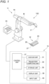
- Fig. 1 is a schematic configuration diagram illustrating an example of an apparatus for manufacturing an additively-manufactured object for carrying out an additive manufacturing method according to the present invention.
- a manufacturing apparatus 100 of an additively-manufactured object of the present configuration is a device that forms an additively-manufactured object or an additively-manufactured object as a blank for obtaining an additively-manufactured object of a desired shape, and includes an additive manufacturing apparatus 11 and a controller 15 that collectively controls the additive manufacturing apparatus 11.
- the additive manufacturing apparatus 11 includes a welding robot 19 having a torch 17 provided on a tip shaft, and a filler metal feeding unit 23 for feeding a filler metal (weld wire) M to the torch 17.
- the torch 17 holds the filler metal M in a state of protruding from the tip.
- the welding robot 19 is an articulated robot, and in the torch 17, the filler metal M is supported such that the filler metal can be continuously fed.
- the position or posture of the torch 17 can be set three-dimensionally desirably within the range of the degree of freedom of the robot arm.
- the torch 17 includes a not-shown shield nozzle, and a shielding gas is supplied from the shield nozzle.
- the arc welding method may be either a consumable electrode type such as shielded metal arc welding or carbon dioxide gas arc welding, or a non-consumable electrode type such as TIG welding or plasma arc welding, and the arc welding method is appropriately selected depending on the additively-manufactured object to be manufactured.
- a contact tip is disposed inside the shield nozzle, and the filler metal M to which a melting current is to be supplied is held on the contact tip.
- the torch 17 generates an arc from the tip of the filler metal M in a shielding gas atmosphere while holding the filler metal M.
- the filler metal M is fed from the filler metal feeding unit 23 to the torch 17 by a not-shown delivery mechanism attached to the robot arm, etc. Then, when the filler metal M fed continuously is melted and solidified while the torch 17 is moved, a linear bead 25 which is a melt-solidified body of the filler metal M is formed on a base plate 27.
- the heat source for melting the filler metal M is not limited to the aforementioned arc.
- a heat source using another system such as a heating system using an arc and a laser together, a heating system using a plasma or a heating system using an electron beam or a laser may be used.
- a heating amount can be controlled more finely to keep each weld bead in a more proper state, thereby contributing to further improvement of the quality of the additively-manufactured object.
- any commercially available weld wire can be used as the filler metal M.
- wires provided as MAG welding and MIG welding solid wires (JIS Z 3312) for mild steel, high tensile steel and cryogenic steel, and arc welding flux cored wires (JIS Z 3313) for mild steel, high tensile steel and cryogenic steel can be used as the filler metal M.
- the controller 15 includes a CAD/CAM unit 31, a trajectory computing unit 33, a storage unit 35, and a control unit 37 to which these units are connected.
- the controller 15 is configured by a computer unit having a CPU, a memory, a storage, and the like.
- the controller 15 further includes a display unit 39 such as a liquid crystal display on which information indicating the shape of the additive manufactured object, information of a trajectory plan indicating a movement trajectory of the torch 17 during additive manufacturing, welding conditions, and the like are displayed, and an input unit 40 such as a keyboard and a mouse for receiving various kinds of input information.
- the CAD/CAM unit 31 reads three-dimensional shape data (CAD data or the like) of the additive manufactured object to be manufactured, divides the three-dimensional model depending on the three-dimensional shape data into a plurality of layers, and generates layer shape data indicating the shape of each layer.
- the trajectory computing unit 33 divides the generated layer shape data into a bead model of the plurality of lines to be described later, and determines a movement trajectory of the torch 17.
- the storage unit 35 stores various types of data including information such as the generated layer shape data and the movement trajectory of the torch 17, and a drive program.
- the control unit 37 executes a drive program created depending on the layer shape data stored in the storage unit 35 and the movement trajectory of the torch 17 to drive the welding robot 19. That is, the welding robot 19 moves the torch 17 along the track trajectory created by the trajectory computing unit 33 in response to a command from the controller 15.
- the manufacturing apparatus 100 of the additively-manufactured object having the above configuration moves the torch 17 by the driving of the welding robot 19 along the movement trajectory of the torch 17 generated from the layer shape data. Along with the movement of the torch 17, the filler metal M is melted, and the melted filler metal M is fed onto the base plate 27. As a result, as illustrated in Fig. 2 , a bead layer 29 in which the plurality of linear beads 25A, 25B, 25C, and 25D are solidified and arranged on the base plate 27 is formed.
- Fig. 2 illustrates the bead layer 29 of the initial layer, but similar bead layers are deposited a plurality of times on the bead layer 29, an additively-manufactured object W having a multilayer structure as illustrated in Fig. 1 is formed.
- the base plate 27 is made of a metal plate such as a steel plate, but is not limited to such a plate shape one, and may be a base having another shape such as a block or a rod shape.
- the additively-manufactured object W described above is formed based on a deposition plan indicating a procedure of depositing and forming a plurality of beads 25.
- the controller 15 illustrated in Fig. 1 generates a drive program based on the deposition plan, and the control unit 37 executes the generated drive program.
- the control unit 37 drives each unit such as the torch 17 of the additive manufacturing apparatus 11 according to the drive program to form a bead.
- the additively-manufactured object W having a desired shape is formed.
- the drive program may be generated by another computer device by inputting required information to another computer device different from the controller 15. In this case, the generated drive program is input to the storage unit 35 of the controller 15 via an appropriate communication unit such as a LAN.
- the above-described deposition plan includes a process of converting the shape of the additively-manufactured object W into an aggregate of a model (bead model) representing a bead shape.
- the bead model has information such as position information (information of a torch movement trajectory) at which the additively-manufactured object W is finally obtained, and information on the size, length, cross-sectional shape, and the like of each bead.
- the controller 15 or the other computer device functioning as the controller 15 displays, on the display unit 39, information on the trajectory plan such as a three-dimensional model depending on the three-dimensional shape data of the additively-manufactured object W, a deposition direction of the bead, a divided layer,,a bead model of a plurality of lines, and the like.
- the controller 15 or the other computer device functioning as the controller 15 displays, on the display unit 39, information on the trajectory plan such as a three-dimensional model depending on the three-dimensional shape data of the additively-manufactured object W, a deposition direction of the bead, a divided layer,,a bead model of a plurality of lines, and the like.
- Fig. 3 is a cross-sectional view illustrating a conventional bead model as a reference example.
- a shape such as an elliptical shape or a substantially crescent shape is widely used in a vertical cross section in the bead longitudinal direction.
- the shape of the bead is approximated to the bead model BM0 having a substantially crescent cross-sectional shape cut along the upper surface (straight line) of the base plate 27 at a radial position PO in the middle of the circle 41 from the center O toward the upper circumference. That is, the shape of the bead is represented by using the bead model BM0 represented by the radius r, the bead height h, the bead width WO, and the cross-sectional area S0.
- the cross-sectional shape does not necessarily coincide with the actual bead cross-sectional shape obtained by welding, and the difference in the cross-sectional shape is a factor that increases the design error.
- the deposition plan is a plan in which beads are continuously formed under a constant welding condition from the viewpoint of construction and quality. Therefore, it is desirable to make the cross-sectional shape of the bead (cross-sectional area S0) constant.
- the shape of the bead model is changed from a crescent shape or an elliptical shape in the related-art to a trapezoid and a parallelogram that are closer to the cross-sectional shape of the actual bead.
- the bead model with a trapezoidal cross-sectional shape (trapezoidal bead model) and a bead model with a parallelogram at the same height (parallelogram bead model) adjacent to each other, there is no overlapping portion described above, and the arithmetic operation of the cross-sectional area of the bead model can be simplified.
- the additive manufacturing method basically has the following steps.
- step (1) to (3) are performed by the controller 15 ( Fig. 1 ) as described above, and the step (5) is performed by driving the welding robot 19 according to the drive program.
- step (4) will be described in detail.
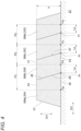
- Fig. 4 is a cross-sectional view showing beads 25A, 25B, 25C, and 25D of an initial layer formed on the base plate 27 illustrated in Fig. 2 and a bead model applied to each bead.
- beads 25A, 25B, 25C, and 25D of an initial layer formed on the base plate 27 illustrated in Fig. 2 and a bead model applied to each bead.
- the number of beads, the bead height h, and the like are arbitrarily set depending on the shape of the additively-manufactured object, the welding condition, and the like.
- the beads 25A, 25B, 25C, and 25D illustrated in Fig. 4 are formed in this order.
- the cross-sectional shape of each of the actual beads 25A, 25B, 25C, and 25D is not necessarily a trapezoidal shape or a parallelogram shape, but at least has a shape that is closer to a trapezoidal shape or a parallelogram shape than a crescent shape or an ellipse, and a high fitting property with the bead model may be obtained.
- the trapezoidal shape refers to a shape in which an upper base 43 and a lower base 45, which are opposite sides in a bead deposition direction DH, are parallel to each other, and lateral sides 47 and 49, which are opposite sides in a bead arrangement direction DV, are non-parallel to each other.
- the parallelogram is a shape in which an upper side 51 and a lower side 53, which are opposite sides in the bead deposition direction DH, are parallel to each other, and lateral sides 55 and 57, which are opposite sides in the bead arrangement direction DV, are parallel to the lateral side 49 of another bead model (trapezoidal bead model BMa) adjacent to the parallelogram. It is assumed that the height h of the trapezoid is equal to the height h of the parallelogram.
- the bead 25A illustrated in Fig. 4 is a bead formed first, and the cross-sectional shape thereof tends to be wider on the lower side (base plate 21 side) than on the upper side. Therefore, the trapezoidal bead model BMa is applied to the bead 25A.
- the bead 25B formed adjacent to the bead 25A is joined to one side surface of the bead 25A by melting a part thereof, and is formed along the bead 25A.
- one lateral side 55 of the bead 25B is joined to the lateral side 49 of the bead 25A adjacent thereto, and accordingly, the other lateral side 57 is substantially parallel to the one lateral side 55. Therefore, the parallelogram bead model BMb is applied to the bead 25B.
- parallelogram bead models BMc and BMd are respectively applied to a bead 25C formed adjacent to the bead 25B and a bead 25D formed adjacent to the bead 25C.
- the trapezoidal bead model is applied to the bead on the first pass in the movement trajectory of the torch, and the parallelogram bead model is applied to the beads on the second and subsequent passes.
- the shape of each bead model is determined so as to match the width and height of the layer to be formed. Further, in order to deposit each bead in the layer at a common height h, it is preferable to finely adjust the target formation positions Pb, Pc, and Pd of the respective beads.
- the distance from an end Pr of a boundary between the bottom side (the lower base 45) of the trapezoidal bead model BMa and the parallelogram bead model BMb adjacent to the trapezoidal bead model BMa to the target formation position Pb of the bead corresponding to the adjacent parallelogram bead model BMb is defined as an adjustment distance Le.
- the distance from the end Pr of the bottom side (lower side 53) of the adjacent parallelogram bead model BMb that forms the bead first on the parallelogram bead model BMc side to the target formation position Pc of the bead is defined as the adjustment distance Le.
- the distance from the end Pr of the bottom side of the parallelogram bead model BMc on the parallelogram bead model BMc side to the target formation position Pd of the bead is defined as the adjustment distance Le.
- the adjustment distance Le is adjusted such that the height h of each bead to be formed is constant. At this time, other welding conditions (welding current, welding voltage, shield gas flow rate, and the like) are regarded as constant. Each adjustment distance Le may be constant or may be set to a different distance. By this adjustment work, pitches Pt 1 , Pt 2 , and Pt 3 between the target formation positions of the respective beads are obtained.
- Fig. 5 is an explanatory view of a bead model in which a plurality of bead layers are deposited on a bead layer of the initial layer.
- parallelogram bead models BMb, BMc, and BMd are arranged adjacent to each other in this order starting from the trapezoidal bead model BMa at the position of the bead layer of the initial layer.
- layers of the trapezoidal bead model BMa and the parallelogram bead models BMb, BMc, and BMd are arranged in a multistage manner on the model layer.
- Each of the pitches Pt 1 , Pt 2 , and Pt 3 has a length finely adjusted by the adjustment distance Le illustrated in Fig. 4 such that the bead height h, h1, h2 of each layer is constant, and a bead width W 0 , W 1 , W 2 , and W 3 corresponding thereto.
- the bead model assembly formed of a plurality of bead models has a solid body width WA and a solid body height HA set to a size in which the size of the additively-manufactured object to be formed is included.
- the three-dimensional model depending on the three-dimensional shape data is divided into a plurality of layers, and each of the divided layers is divided into the trapezoidal bead model and the parallelogram bead model, and each bead model is arranged depending on the formation order of the beads. Then, the additively-manufactured object is formed by repeating the process of forming the bead along the arranged bead model from the lower layer to the upper layer of the plurality of divided layers.
- the procedure of the process of forming the bead along the arranged bead model is performed by the execution of the above-described drive program. As a result, a desired additively-manufactured object can be accurately and efficiently formed.
- various feature points such as an end portion, a top portion, a bottom side, an upper side, and an oblique side of the model, and various parameters such as a pitch, a bead height, a bead width, a solid body width, and a solid body height
- various parameters such as a pitch, a bead height, a bead width, a solid body width, and a solid body height
- each bead model is a simple shape in which the curved portion does not exist, the extraction of the bead boundary, the evaluation of the bead height and the bead width can be easily performed. Therefore, the number of passes and layers for bead formation can be easily and accurately estimated from the shape information of the additively-manufactured object such as CAD data, and the deposition plan is not complicated.
- the re-planning can be simply performed even when various conditions such as the position of the end portion of the additively-manufactured object, the repeated welding condition, the pitch of the target formation position of the bead, and the like are changed, the design change can be easily performed.
- a step of setting welding conditions capable of realizing the above-described deposition plan is also required.
- information of a building result by combining conditions of a trapezoidal bead model and a parallelogram bead model having a predetermined width and height and welding conditions are stored in a database, and the correspondence relationship between the model condition and the welding condition can be easily referred to.
- a welding condition suitable for the bead model can be determined using the database, and a more appropriate bead can be formed.
- the bead width of the bead model of the portion corresponding to the outer edge and the excess thickness portion of the three-dimensional model may be changed depending on the excess thickness amount of the excess thickness portion (the excess thickness in the cross section orthogonal to the bead longitudinal direction).
- the excess thickness portion is provided in the three-dimensional model, it is possible to change the outer shape without repeating a complicated arithmetic operation simply by changing the bead model adjacent to the position of the excess thickness portion, that is, the width (bead width) of the bead model of the end portion.
- the trapezoidal bead model and the parallelogram bead model described in the first additive manufacturing method are models that can easily predict the shape after building. However, when it is desired to search for the building conditions more accurately, the overlap amount with the adjacent bead may be evaluated, and the bead model obtained by the first additive manufacturing method may be corrected.
- a bead model partially circular bead model
- the overlap amount with the adjacent bead is taken into account to realize a bead model that can be deposited and designed with high accuracy.
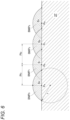
- Fig. 6 is a schematic explanatory view of a partial circular model
- Fig. 7 is a detailed explanatory view geometrically illustrating the model illustrated in Fig. 6 .
- partial circular bead models BMP 0 , BMP 1 , BMP 2 , and BMP 3 having a circumference (arc) with a radius r are used.
- an overlapping portion is formed between the arcs of the adjacent bead models.
- the overlap of the bead is represented by the overlap amount (cross feed length) Cf as illustrated in Fig. 7 .
- the overlap amount Cf can be expressed by a relational expression between the above-described bead width W 0 and the adjustment distance Le, as represented by the following formula (1).
- Cf 1 / 2 W 0 ⁇ Le
- the overlap amount Cf is set to an appropriate value at which welding defects obtained in advance are less likely to occur. That is, the adjustment distance Le determined using the above-described trapezoidal bead model and parallelogram bead model is corrected depending on the set overlap amount Cf of the partial circular bead model. Accordingly, the pitches Pt 1 , Pt 2 , and Pt 3 (see Fig. 4 ) of the respective beads can be set more appropriately.
- the fitting of the partial circular bead model BMP 0 to the trapezoidal bead model BMa is performed by selecting a radius r at which the circumference of the partial circular bead model BMP 0 has a common difference with both ends of the lower base 45 of the trapezoidal bead model BMa and is tangent to the upper base 43 of the trapezoidal bead model.
- the radius r may be selected such that the area of the partial circular bead model BMP 0 is a desired cross-sectional area S 0 .
- a virtual reference circle 61 having a radius r that passes through both end portions Ps and Pr of the lower base 45 of the trapezoidal bead model BMa and is tangent to the upper base 43 is defined.
- a virtual circle 63 passing through the end portion Pr of the lower side 53 of the parallelogram bead model BMb adjacent to the trapezoidal bead model BMa on the side opposite to the trapezoidal bead model BMa side and being tangent to the upper side 51 is defined so as to overlap at least a part of the virtual reference circle 61.
- the adjustment distance Le is corrected such that the overlap amount Cf is the value obtained in advance.
- the virtual circle is obtained by determining the radius r at which the cross-sectional area S 1 may be determined to be equal to the cross-sectional area S 0 of the trapezoidal bead model BMa.
- the pitch Pt 1 between the target formation positions Pa and Pb of the beads is changed depending on the position of the virtual circle 63 determined in this way.
- the adjustment distance Le is corrected such that the overlap amount Cf of the bead model is the above-described set value or the cross-sectional areas S 2 and S 3 are equal to each other, and the pitches Pt 2 and Pt 3 of the target formation positions Pc and Pd of the beads are changed.
- the target formation position of the bead is corrected using the partial circular model such that the overlap amount Cf of each partial circular model is a desired value. Accordingly, it is possible to determine a more accurate bead formation position in consideration of the overlapping portion of the beads, and it is possible to further improve the accuracy of the deposition plan.
- the deposition plan considering the overlapping portion of the beads can be performed without complicating the arithmetic operation processing, and the shape deviation between the bead model and the actual bead can be reduced.
- This method can also be used to verify the validity of the adjustment distance Le set by the trapezoidal bead model and the parallelogram bead model in the first additive manufacturing method.
- a weld metal such as a melted filler metal may drop down from an end portion of the base plate 27.
- a start point of bead formation is provided inside the end portion of the base plate 27.
- the beads parallelogram bead models BMb, BMc, BMd, BMe
- the beads are alternately formed on both sides of the starting bead (trapezoidal bead model BMa) around the starting bead.
- the end portion of the bead row indicated by the dotted line is disposed at the end portion of the base plate 27, at the time of bead formation, the arc generated from the torch 17 approaches the existing bead side. Therefore, even when a bead is formed on the end portion of the base plate 27, it can be inferred that dripping of the weld metal is suppressed.
- An additive manufacturing method for preparing a built-up object by depositing a bead formed by melting and solidifying a filler metal on a base including:
- the number of passes and layers for bead formation can be easily and accurately estimated from the shape of the additively-manufactured object, and the deposition plan is not complicated.
- the re-planning can be simply performed even when various conditions such as the position of the end portion of the additively-manufactured object, the repeated welding condition, the pitch of the target formation position of the bead, and the like are changed, the design change can be easily performed.
- the additive manufacturing method including a step of changing a welding condition of the bead according to a height and a width of the bead model in the vertical cross section by referring to a database in which building results obtained based on a combination of a plurality of types of welding conditions, bead heights, and bead widths are stored.
- a more appropriate bead can be formed by determining the welding condition depending on the bead model with reference to the database.
- the height of each bead in the layer can be made uniform by appropriately adjusting the adjustment distance.
- the additive manufacturing method including a step of applying a partial circular bead model having an arc at least in a part of the vertical cross section to the trapezoidal bead model and the parallelogram bead model respectively, wherein in the step, the adjustment distance is corrected such that overlapping of the arcs of the partial circular bead models adjacent to each other has a predetermined overlap amount.
- the bead model can be determined in consideration of the overlap amount between the beads, and a more accurate deposition plan can be realized.
- the number of passes and layers for bead formation can be easily and accurately estimated from the shape of the additively-manufactured object, and the deposition plan is not complicated.
- the re-planning can be simply performed even when various conditions such as the position of the end portion of the additively-manufactured object, the repeated welding condition, the pitch of the target formation position of the bead, and the like are changed, the design change can be easily performed.
- a controller configured to read three-dimensional shape data of a built-up object formed by depositing a bead formed by melting and solidifying a filler metal on a base by a torch, determine a deposition direction of the bead depending on a three-dimensional model shape of the three-dimensional shape data, divide the three-dimensional model shape into a plurality of layers along the deposition direction, divide the divided layers into a bead model of a plurality of lines depending on the bead shape in the formation order of the bead, and determine a trajectory plan of the torch, wherein in a case of dividing into the bead model of the plurality of lines, the controller
- the deposition plan can be determined without requiring complicated arithmetic operation.
- the controller according to the above, further including a display unit configured to display information of the trajectory plan.
- the deposition plan by displaying the deposition plan on the display unit, the deposition plan can be visually understood by the operator, and the operator can support the generation and the determination work of the deposition plan.
- the controller according to the above, further including an input unit configured to receive input information for changing information of the trajectory plan.
- the trajectory plan can be arbitrarily changed according to the input information received by the input unit.
Landscapes
- Engineering & Computer Science (AREA)
- Physics & Mathematics (AREA)
- Mechanical Engineering (AREA)
- Plasma & Fusion (AREA)
- Theoretical Computer Science (AREA)
- Chemical & Material Sciences (AREA)
- Optics & Photonics (AREA)
- Materials Engineering (AREA)
- Manufacturing & Machinery (AREA)
- Robotics (AREA)
- Computer Hardware Design (AREA)
- General Physics & Mathematics (AREA)
- General Engineering & Computer Science (AREA)
- Geometry (AREA)
- Evolutionary Computation (AREA)
- Automation & Control Theory (AREA)
- Butt Welding And Welding Of Specific Article (AREA)
- Arc Welding In General (AREA)
- Laser Beam Processing (AREA)
- Welding Or Cutting Using Electron Beams (AREA)
Claims (10)
- Additives Herstellungsverfahren zum Herstellen eines zusammengesetzten Objekts durch Abscheiden eines Wulstes, der durch Schmelzen und Verfestigen eines Füllmetalls auf einer Basis gebildet wird, wobei das Verfahren umfasst:einen Schritt des Lesens dreidimensionaler Formdaten des zusammengesetzten Objekts;einen Schritt des Bestimmens einer Abscheidungsrichtung des Wulstes in Abhängigkeit von einer dreidimensionalen Modellform der dreidimensionalen Formdaten;einen Schritt des Teilens der dreidimensionalen Modellform in eine Mehrzahl von Schichten entlang der Abscheidungsrichtung;einen Schritt des Teilens jeder Schicht, die geteilt ist, in ein Wulstmodell einer Mehrzahl von Linien in Abhängigkeit von einer Wulstform in einer Bildungsreihenfolge des Wulstes; undeinen Schritt des Bereitstellens des zusammengesetzten Objekts durch Wiederholen eines Prozesses des Bildens des Wulstes entlang des Wulstmodells von einer unteren Schicht zu einer oberen Schicht der Mehrzahl von Schichten, wobei,in dem Schritt des Teilens in das Wulstmodell der Mehrzahl von Linien,an einer Position, an der der Wulst in einem Abschnitt gebildet wird, der nicht an einen bestehenden Wulst in der Schicht angrenzend ist, ein trapezförmiges Wulstmodell, von welchem ein vertikaler Querschnitt in einer Wulstlängsrichtung eine Trapezform ist, aufgebracht wird, wobei in dem trapezförmigen Wulstmodell gegenüberliegende Seiten in der Abscheidungsrichtung des Wulstes parallel zueinander sind und gegenüberliegende Seiten in einer Wulstanordnungsrichtung in der Schicht nicht parallel zueinander sind, und,an einer Position, an der der Wulst angrenzend zu einem Wulst, der bereits gebildet wurde, gebildet wird, ein Parallelogramm-Wulstmodell, von welchem ein vertikaler Querschnitt in der Wulstlängsrichtung ein Parallelogramm ist, aufgebracht wird, wobei in dem Parallelogramm-Wulstmodell gegenüberliegende Seiten in der Abscheidungsrichtung des Wulstes parallel zueinander sind und gegenüberliegende Seiten in der Wulstanordnungsrichtung parallel zu einer Seite eines anderen Wulstmodells, das angrenzend ist, sind.
- Additives Herstellungsverfahren nach Anspruch 1, umfassend
einen Schritt des Änderns einer Schweißbedingung des Wulstes entsprechend einer Höhe und einer Breite des Wulstmodells in dem vertikalen Querschnitt durch Bezugnehmen auf eine Datenbank, in welcher Erstellungsergebnisse gespeichert sind, die basierend auf einer Kombination einer Mehrzahl von Typen von Schweißbedingungen, Wulsthöhen und Wulstbreiten erhalten wurden. - Additives Herstellungsverfahren nach Anspruch 1 oder 2, umfassendeinen Schritt des Hinzufügens eines Überschuss-Dickenabschnitts zu einer Außenkante der dreidimensionalen Modellform, undeinen Schritt des Änderns einer Breite eines angrenzenden Wulstmodells, das zu einer Position des hinzugefügten Überschuss-Dickenabschnitts angrenzend ist, in Abhängigkeit von einer Breite des Überschuss-Dickenabschnitts in dem vertikalen Querschnitt in Bezug auf das angrenzende Wulstmodell.
- Additives Herstellungsverfahren nach Anspruch 1 oder 2, wobei
ein Anpassungsabstand von einer Grenzposition zwischen Basen eines Paares von Wulstmodellen, die angrenzend zueinander in einer gleichen Schicht angeordnet sind, zu einer Wulstzielbildungsposition eines Wulstmodells in dem Paar von Wulstmodellen mit einer späteren Wulstbildungsreihenfolge so bestimmt wird, dass eine Höhe des Wulstes in der Schicht konstant ist. - Additives Fertigungsverfahren nach Anspruch 4, umfassend:einen Schritt des Aufbringens eines teilkreisförmigen Wulstmodells mit einem Bogen zumindest in einem Teil des vertikalen Querschnitts jeweils auf das trapezförmige Wulstmodell und das Parallelogramm-Wulstmodell,wobei in dem Schritt der Anpassungsabstand so korrigiert wird, dass das Überlappen der Bögen der teilkreisförmigen Wulstmodelle, die aneinander angrenzend sind, eine vorbestimmte Überlappungsmenge aufweist.
- Herstellungsvorrichtung zum Herstellen eines additiv hergestellten Objekts (W), um ein zusammengesetztes Objekt durch Abscheiden eines Wulstes (25) bereitzustellen, der durch Schmelzen und Verfestigen eines Füllmetalls auf einer Basis (27) durch einen Brenner (17) gebildet wird, wobei die Herstellungsvorrichtung (11) umfasst:eine Steuerung (15), die konfiguriert ist, dreidimensionale Formdaten des zusammengesetzten Objekts zu lesen, eine Abscheidungsrichtung des Wulstes (DH) in Abhängigkeit von einer dreidimensionalen Modellform der dreidimensionalen Formdaten zu bestimmen, die dreidimensionale Modellform in eine Mehrzahl von Schichten entlang der Abscheidungsrichtung (DH) zu teilen, jede Schicht, die geteilt ist, in ein Wulstmodell einer Mehrzahl von Linien in Abhängigkeit von einer Wulstform in einer Bildungsreihenfolge des Wulstes (25) zu teilen und einen Trajektorienplan des Brenners (17) zu bestimmen; undeine Vorrichtung (11) zum additiven Herstellen, die konfiguriert ist, das zusammengesetzte Objekt durch Wiederholen eines Prozesses des Bildens des Wulstes (25) entlang des Wulstmodells von einer unteren Schicht zu einer oberen Schicht der Mehrzahl von Schichten bereitzustellen, wobei,in einem Fall des Teilens in das Wulstmodell der Mehrzahl von Linien, die Steuerung (15)an einer Position, an der der Wulst (25) in einem Abschnitt gebildet wird, der nicht an einen bestehenden Wulst (25) in der Schicht angrenzend ist, ein trapezförmiges Wulstmodell aufbringt, von welchem ein vertikaler Querschnitt in einer Wulstlängsrichtung eine Trapezform ist, wobei in dem trapezförmigen Wulstmodell gegenüberliegende Seiten in der Abscheidungsrichtung (DH) des Wulstes parallel zueinander sind und gegenüberliegende Seiten in einer Wulstanordnungsrichtung (DV) in der Schicht nicht parallel zueinander sind, und,an einer Position, an der der Wulst (25) angrenzend zu einem Wulst (25), der bereits gebildet wurde, gebildet wird, ein Parallelogramm-Wulstmodell aufbringt, von welchem ein vertikaler Querschnitt in der Wulstlängsrichtung ein Parallelogramm ist, wobei in dem Parallelogramm-Wulstmodell gegenüberliegende Seiten in der Abscheidungsrichtung (DH) des Wulstes parallel zueinander sind und gegenüberliegende Seiten in der Wulstanordnungsrichtung (DV) parallel zu einer Seite eines anderen Wulstmodells, das angrenzend ist, sind.
- Steuerung, die konfiguriert ist, dreidimensionale Formdaten eines zusammengesetzten Objekts zu lesen, das durch Abscheiden eines Wulstes gebildet wird, der durch Schmelzen und Verfestigen eines Füllmetalls auf einer Basis durch einen Brenner gebildet wird, eine Abscheidungsrichtung des Wulstes in Abhängigkeit von einer dreidimensionalen Modellform der dreidimensionalen Formdaten zu bestimmen, die dreidimensionale Modellform in eine Mehrzahl von Schichten entlang der Abscheidungsrichtung zu teilen, die geteilten Schichten in ein Wulstmodell einer Mehrzahl von Linien in Abhängigkeit von der Wulstform in der Bildungsreihenfolge des Wulstes zu teilen und einen Bahnverlaufsplan des Brenners zu bestimmen, wobei
in einem Fall des Teilens in das Wulstmodell der Mehrzahl von Linien die Steuerungan einer Position, an der der Wulst in einem Abschnitt gebildet wird, der nicht an einen bestehenden Wulst in der Schicht angrenzend ist, ein trapezförmiges Wulstmodell aufbringt, von welchem ein vertikaler Querschnitt in einer Wulstlängsrichtung eine Trapezform ist, wobei in dem trapezförmigen Wulstmodell gegenüberliegende Seiten in der Abscheidungsrichtung des Wulstes parallel zueinander sind und gegenüberliegende Seiten in einer Wulstanordnungsrichtung in der Schicht nicht parallel zueinander sind, und,an einer Position, an der der Wulst angrenzend zu einem Wulst, der bereits gebildet wurde, gebildet wird, ein Parallelogramm-Wulstmodell aufbringt, von welchem ein vertikaler Querschnitt in der Wulstlängsrichtung ein Parallelogramm ist, wobei in dem Parallelogramm-Wulstmodell gegenüberliegende Seiten in der Abscheidungsrichtung des Wulstes parallel zueinander sind und gegenüberliegende Seiten in der Wulstanordnungsrichtung parallel zu einer Seite eines anderen Wulstmodells, das angrenzend ist, sind. - Steuerung nach Anspruch 7, weiter umfassend eine Anzeigeeinheit, die konfiguriert ist, eine Information des Bahnverlaufsplans anzuzeigen.
- Steuerung nach Anspruch 8, weiter umfassend eine Eingabeeinheit, die konfiguriert ist, Eingabeinformationen zum Ändern der Information des Bahnverlaufsplans zu empfangen.
- Steuerung nach Anspruch 8, wobeidie Information des Bahnverlaufsplans einen Merkmalspunkt enthält, der eine Form von mindestens einem von dem trapezförmigen Wulstmodell und dem Parallelogramm-Wulstmodell darstellt, unddie Steuerung die Formen des trapezförmigen Wulstmodells und des Parallelogramm-Wulstmodells in Abhängigkeit der Eingabeinformationen, die durch die Eingabeeinheit empfangen wurden, ändert.
Applications Claiming Priority (2)
| Application Number | Priority Date | Filing Date | Title |
|---|---|---|---|
| JP2019118745A JP6797244B1 (ja) | 2019-06-26 | 2019-06-26 | 積層造形方法 |
| PCT/JP2020/024378 WO2020262291A1 (ja) | 2019-06-26 | 2020-06-22 | 積層造形方法、積層造形装置及びコントローラ |
Publications (3)
| Publication Number | Publication Date |
|---|---|
| EP3974091A1 EP3974091A1 (de) | 2022-03-30 |
| EP3974091A4 EP3974091A4 (de) | 2022-08-10 |
| EP3974091B1 true EP3974091B1 (de) | 2024-11-27 |
Family
ID=73646786
Family Applications (1)
| Application Number | Title | Priority Date | Filing Date |
|---|---|---|---|
| EP20833390.6A Active EP3974091B1 (de) | 2019-06-26 | 2020-06-22 | Generatives fertigungsverfahren, generative fertigungsvorrichtung und regler |
Country Status (5)
| Country | Link |
|---|---|
| US (1) | US12296414B2 (de) |
| EP (1) | EP3974091B1 (de) |
| JP (1) | JP6797244B1 (de) |
| CN (1) | CN114007794B (de) |
| WO (1) | WO2020262291A1 (de) |
Families Citing this family (13)
| Publication number | Priority date | Publication date | Assignee | Title |
|---|---|---|---|---|
| DE112020006920T5 (de) * | 2020-03-19 | 2022-12-29 | Mitsubishi Electric Corporation | Einrichtung zur erzeugung von pfaden für additive fertigung, verfahren zur erzeugung von pfaden für additive fertigung und einrichtung für maschinelles lernen |
| JP7311481B2 (ja) * | 2020-12-11 | 2023-07-19 | 株式会社神戸製鋼所 | 積層造形方法及び積層造形装置、並びにモデル表示装置 |
| JP7575955B2 (ja) | 2021-01-13 | 2024-10-30 | キヤノン株式会社 | 制御装置、システム、リソグラフィ装置、物品の製造方法、制御方法及びプログラム |
| JP7505999B2 (ja) * | 2021-01-29 | 2024-06-25 | 株式会社神戸製鋼所 | 積層造形物の変形予測方法 |
| JP7827501B2 (ja) * | 2021-08-20 | 2026-03-10 | 株式会社神戸製鋼所 | 軌道計画作成支援方法、軌道計画作成支援装置、積層造形方法、積層造形装置及びプログラム |
| EP4375000B1 (de) * | 2021-08-20 | 2026-05-06 | Kabushiki Kaisha Kobe Seiko Sho (Kobe Steel, Ltd.) | Verfahren zur unterstützung der erstellung eines trajektorienplans zur bildung einer schweissraupe während einer additiven fertigung |
| CN113792028B (zh) * | 2021-08-26 | 2024-04-16 | 上海航天精密机械研究所 | 一种电弧增材制造沉积层的工艺数据库构建方法 |
| US12485498B2 (en) * | 2022-03-31 | 2025-12-02 | Hcl Technologies Limited | Method and system of identifying a weldment feature |
| JP7817067B2 (ja) * | 2022-04-22 | 2026-02-18 | コベルコROBOTiX株式会社 | 積層設計方法、溶接条件設定方法、溶接制御方法、溶接制御装置、および溶接システム |
| JP7687994B2 (ja) * | 2022-06-06 | 2025-06-03 | 株式会社神戸製鋼所 | 造形計画支援装置およびプログラム |
| US12521884B2 (en) * | 2022-07-26 | 2026-01-13 | Path Robotics, Inc. | Techniques for multipass welding |
| CN117300360B (zh) * | 2023-11-28 | 2024-01-30 | 山东创瑞激光科技有限公司 | 一种结合电弧送丝技术的激光铺粉增材制造方法 |
| CN117583698B (zh) * | 2024-01-19 | 2024-04-26 | 中建材(合肥)粉体科技装备有限公司 | 一种自动堆焊装置及堆焊控制方法 |
Family Cites Families (9)
| Publication number | Priority date | Publication date | Assignee | Title |
|---|---|---|---|---|
| JP2010201474A (ja) * | 2009-03-04 | 2010-09-16 | Toshiba Corp | 溶接最適化方法及びシステム並びに溶接方法 |
| CN201728479U (zh) * | 2010-06-12 | 2011-02-02 | 青岛东方铁塔股份有限公司 | 板材焊接接口 |
| JP6804298B2 (ja) * | 2014-11-14 | 2020-12-23 | 株式会社ニコン | 造形装置 |
| JP6887755B2 (ja) * | 2016-02-16 | 2021-06-16 | 株式会社神戸製鋼所 | 積層制御装置、積層制御方法及びプログラム |
| JP6754118B2 (ja) * | 2016-08-18 | 2020-09-09 | 国立大学法人埼玉大学 | 三次元造形のためのコンピュータ支援製造装置,方法およびプログラム,三次元造形のための制御プログラム生成装置,ならびに三次元造形システム |
| CN206677434U (zh) * | 2017-03-23 | 2017-11-28 | 广州容柏生建筑结构设计事务所 | 一种建筑钢结构墙、柱构件自动焊接装置 |
| JP6802773B2 (ja) * | 2017-10-23 | 2020-12-23 | 株式会社神戸製鋼所 | 積層造形物の製造方法及び積層造形物 |
| JP7077023B2 (ja) | 2018-01-11 | 2022-05-30 | 株式会社三共 | 遊技機 |
| CN109145524B (zh) * | 2018-10-31 | 2023-04-18 | 哈尔滨阿尔特机器人技术有限公司 | 排布坡口焊道的多层多道获取方法 |
-
2019
- 2019-06-26 JP JP2019118745A patent/JP6797244B1/ja active Active
-
2020
- 2020-06-22 US US17/622,612 patent/US12296414B2/en active Active
- 2020-06-22 WO PCT/JP2020/024378 patent/WO2020262291A1/ja not_active Ceased
- 2020-06-22 EP EP20833390.6A patent/EP3974091B1/de active Active
- 2020-06-22 CN CN202080045113.7A patent/CN114007794B/zh active Active
Also Published As
| Publication number | Publication date |
|---|---|
| US12296414B2 (en) | 2025-05-13 |
| US20220355407A1 (en) | 2022-11-10 |
| JP6797244B1 (ja) | 2020-12-09 |
| EP3974091A1 (de) | 2022-03-30 |
| JP2021003724A (ja) | 2021-01-14 |
| CN114007794A (zh) | 2022-02-01 |
| WO2020262291A1 (ja) | 2020-12-30 |
| EP3974091A4 (de) | 2022-08-10 |
| CN114007794B (zh) | 2023-01-24 |
Similar Documents
| Publication | Publication Date | Title |
|---|---|---|
| EP3974091B1 (de) | Generatives fertigungsverfahren, generative fertigungsvorrichtung und regler | |
| JP6797324B1 (ja) | 積層造形方法 | |
| EP4183509B1 (de) | System zur herstellung eines laminatformprodukts, verfahren zur herstellung eines laminatformprodukts und programm zur herstellung eines laminatformprodukts | |
| US12547140B2 (en) | Stacking plan creating method | |
| EP4275832B1 (de) | Verfahren zur herstellung eines laminierungsplans | |
| EP3711889B1 (de) | Verfahren und vorrichtung zum herstellen eines aufgebauten objekts durch schmelzen und erstarren eines zusatzsmetalls | |
| US20230302563A1 (en) | Method for manufacturing multi-layer molded article | |
| JPH0999368A (ja) | 自動溶接装置 | |
| JP7381422B2 (ja) | 造形物の製造方法及び造形物 | |
| EP4241912B1 (de) | Verfahren zur generativen fertigung und vorrichtung zur generativen fertigung | |
| EP4549071A1 (de) | Steuerungsinformationskorrekturverfahren, steuerungsinformationskorrekturvorrichtung und programm | |
| KR20250095693A (ko) | 적응형 용접 | |
| JP6859471B1 (ja) | 積層造形物の製造方法 | |
| CN117836082A (zh) | 造型装置的控制方法、造型装置以及程序 | |
| JP7687994B2 (ja) | 造形計画支援装置およびプログラム | |
| JP7623333B2 (ja) | 積層造形装置の制御情報修正方法、制御情報修正装置及びプログラム |
Legal Events
| Date | Code | Title | Description |
|---|---|---|---|
| STAA | Information on the status of an ep patent application or granted ep patent |
Free format text: STATUS: THE INTERNATIONAL PUBLICATION HAS BEEN MADE |
|
| PUAI | Public reference made under article 153(3) epc to a published international application that has entered the european phase |
Free format text: ORIGINAL CODE: 0009012 |
|
| STAA | Information on the status of an ep patent application or granted ep patent |
Free format text: STATUS: REQUEST FOR EXAMINATION WAS MADE |
|
| 17P | Request for examination filed |
Effective date: 20211223 |
|
| AK | Designated contracting states |
Kind code of ref document: A1 Designated state(s): AL AT BE BG CH CY CZ DE DK EE ES FI FR GB GR HR HU IE IS IT LI LT LU LV MC MK MT NL NO PL PT RO RS SE SI SK SM TR |
|
| A4 | Supplementary search report drawn up and despatched |
Effective date: 20220708 |
|
| RIC1 | Information provided on ipc code assigned before grant |
Ipc: G06F 30/10 20200101ALI20220704BHEP Ipc: B33Y 50/00 20150101ALI20220704BHEP Ipc: B33Y 10/00 20150101ALI20220704BHEP Ipc: B23K 26/348 20140101ALI20220704BHEP Ipc: B23K 26/34 20140101ALI20220704BHEP Ipc: B23K 26/21 20140101ALI20220704BHEP Ipc: B23K 15/00 20060101ALI20220704BHEP Ipc: B23K 9/16 20060101ALI20220704BHEP Ipc: B23K 9/032 20060101ALI20220704BHEP Ipc: B23K 9/04 20060101AFI20220704BHEP |
|
| DAV | Request for validation of the european patent (deleted) | ||
| DAX | Request for extension of the european patent (deleted) | ||
| GRAP | Despatch of communication of intention to grant a patent |
Free format text: ORIGINAL CODE: EPIDOSNIGR1 |
|
| STAA | Information on the status of an ep patent application or granted ep patent |
Free format text: STATUS: GRANT OF PATENT IS INTENDED |
|
| RIC1 | Information provided on ipc code assigned before grant |
Ipc: B23K 9/095 20060101ALI20240531BHEP Ipc: B33Y 30/00 20150101ALI20240531BHEP Ipc: B33Y 50/02 20150101ALI20240531BHEP Ipc: G06F 30/20 20200101ALI20240531BHEP Ipc: B33Y 50/00 20150101ALI20240531BHEP Ipc: B33Y 10/00 20150101ALI20240531BHEP Ipc: B23K 26/348 20140101ALI20240531BHEP Ipc: B23K 26/342 20140101ALI20240531BHEP Ipc: B23K 26/21 20140101ALI20240531BHEP Ipc: B23K 15/00 20060101ALI20240531BHEP Ipc: B23K 9/16 20060101ALI20240531BHEP Ipc: B23K 9/032 20060101ALI20240531BHEP Ipc: B23K 9/04 20060101AFI20240531BHEP |
|
| INTG | Intention to grant announced |
Effective date: 20240625 |
|
| P01 | Opt-out of the competence of the unified patent court (upc) registered |
Free format text: CASE NUMBER: APP_48620/2024 Effective date: 20240826 |
|
| GRAS | Grant fee paid |
Free format text: ORIGINAL CODE: EPIDOSNIGR3 |
|
| GRAA | (expected) grant |
Free format text: ORIGINAL CODE: 0009210 |
|
| STAA | Information on the status of an ep patent application or granted ep patent |
Free format text: STATUS: THE PATENT HAS BEEN GRANTED |
|
| AK | Designated contracting states |
Kind code of ref document: B1 Designated state(s): AL AT BE BG CH CY CZ DE DK EE ES FI FR GB GR HR HU IE IS IT LI LT LU LV MC MK MT NL NO PL PT RO RS SE SI SK SM TR |
|
| REG | Reference to a national code |
Ref country code: GB Ref legal event code: FG4D |
|
| REG | Reference to a national code |
Ref country code: CH Ref legal event code: EP |
|
| REG | Reference to a national code |
Ref country code: IE Ref legal event code: FG4D |
|
| REG | Reference to a national code |
Ref country code: DE Ref legal event code: R096 Ref document number: 602020042196 Country of ref document: DE |
|
| REG | Reference to a national code |
Ref country code: LT Ref legal event code: MG9D |
|
| REG | Reference to a national code |
Ref country code: NL Ref legal event code: MP Effective date: 20241127 |
|
| PG25 | Lapsed in a contracting state [announced via postgrant information from national office to epo] |
Ref country code: PT Free format text: LAPSE BECAUSE OF FAILURE TO SUBMIT A TRANSLATION OF THE DESCRIPTION OR TO PAY THE FEE WITHIN THE PRESCRIBED TIME-LIMIT Effective date: 20250327 Ref country code: HR Free format text: LAPSE BECAUSE OF FAILURE TO SUBMIT A TRANSLATION OF THE DESCRIPTION OR TO PAY THE FEE WITHIN THE PRESCRIBED TIME-LIMIT Effective date: 20241127 Ref country code: IS Free format text: LAPSE BECAUSE OF FAILURE TO SUBMIT A TRANSLATION OF THE DESCRIPTION OR TO PAY THE FEE WITHIN THE PRESCRIBED TIME-LIMIT Effective date: 20250327 |
|
| PG25 | Lapsed in a contracting state [announced via postgrant information from national office to epo] |
Ref country code: FI Free format text: LAPSE BECAUSE OF FAILURE TO SUBMIT A TRANSLATION OF THE DESCRIPTION OR TO PAY THE FEE WITHIN THE PRESCRIBED TIME-LIMIT Effective date: 20241127 Ref country code: NL Free format text: LAPSE BECAUSE OF FAILURE TO SUBMIT A TRANSLATION OF THE DESCRIPTION OR TO PAY THE FEE WITHIN THE PRESCRIBED TIME-LIMIT Effective date: 20241127 |
|
| REG | Reference to a national code |
Ref country code: AT Ref legal event code: MK05 Ref document number: 1745265 Country of ref document: AT Kind code of ref document: T Effective date: 20241127 |
|
| PG25 | Lapsed in a contracting state [announced via postgrant information from national office to epo] |
Ref country code: BG Free format text: LAPSE BECAUSE OF FAILURE TO SUBMIT A TRANSLATION OF THE DESCRIPTION OR TO PAY THE FEE WITHIN THE PRESCRIBED TIME-LIMIT Effective date: 20241127 |
|
| PG25 | Lapsed in a contracting state [announced via postgrant information from national office to epo] |
Ref country code: ES Free format text: LAPSE BECAUSE OF FAILURE TO SUBMIT A TRANSLATION OF THE DESCRIPTION OR TO PAY THE FEE WITHIN THE PRESCRIBED TIME-LIMIT Effective date: 20241127 |
|
| PG25 | Lapsed in a contracting state [announced via postgrant information from national office to epo] |
Ref country code: NO Free format text: LAPSE BECAUSE OF FAILURE TO SUBMIT A TRANSLATION OF THE DESCRIPTION OR TO PAY THE FEE WITHIN THE PRESCRIBED TIME-LIMIT Effective date: 20250227 |
|
| PG25 | Lapsed in a contracting state [announced via postgrant information from national office to epo] |
Ref country code: GR Free format text: LAPSE BECAUSE OF FAILURE TO SUBMIT A TRANSLATION OF THE DESCRIPTION OR TO PAY THE FEE WITHIN THE PRESCRIBED TIME-LIMIT Effective date: 20250228 Ref country code: AT Free format text: LAPSE BECAUSE OF FAILURE TO SUBMIT A TRANSLATION OF THE DESCRIPTION OR TO PAY THE FEE WITHIN THE PRESCRIBED TIME-LIMIT Effective date: 20241127 Ref country code: LV Free format text: LAPSE BECAUSE OF FAILURE TO SUBMIT A TRANSLATION OF THE DESCRIPTION OR TO PAY THE FEE WITHIN THE PRESCRIBED TIME-LIMIT Effective date: 20241127 |
|
| PG25 | Lapsed in a contracting state [announced via postgrant information from national office to epo] |
Ref country code: PL Free format text: LAPSE BECAUSE OF FAILURE TO SUBMIT A TRANSLATION OF THE DESCRIPTION OR TO PAY THE FEE WITHIN THE PRESCRIBED TIME-LIMIT Effective date: 20241127 |
|
| PG25 | Lapsed in a contracting state [announced via postgrant information from national office to epo] |
Ref country code: RS Free format text: LAPSE BECAUSE OF FAILURE TO SUBMIT A TRANSLATION OF THE DESCRIPTION OR TO PAY THE FEE WITHIN THE PRESCRIBED TIME-LIMIT Effective date: 20250227 |
|
| PG25 | Lapsed in a contracting state [announced via postgrant information from national office to epo] |
Ref country code: SM Free format text: LAPSE BECAUSE OF FAILURE TO SUBMIT A TRANSLATION OF THE DESCRIPTION OR TO PAY THE FEE WITHIN THE PRESCRIBED TIME-LIMIT Effective date: 20241127 |
|
| PGFP | Annual fee paid to national office [announced via postgrant information from national office to epo] |
Ref country code: DE Payment date: 20250429 Year of fee payment: 6 |
|
| PG25 | Lapsed in a contracting state [announced via postgrant information from national office to epo] |
Ref country code: DK Free format text: LAPSE BECAUSE OF FAILURE TO SUBMIT A TRANSLATION OF THE DESCRIPTION OR TO PAY THE FEE WITHIN THE PRESCRIBED TIME-LIMIT Effective date: 20241127 |
|
| PGFP | Annual fee paid to national office [announced via postgrant information from national office to epo] |
Ref country code: GB Payment date: 20250501 Year of fee payment: 6 |
|
| PG25 | Lapsed in a contracting state [announced via postgrant information from national office to epo] |
Ref country code: EE Free format text: LAPSE BECAUSE OF FAILURE TO SUBMIT A TRANSLATION OF THE DESCRIPTION OR TO PAY THE FEE WITHIN THE PRESCRIBED TIME-LIMIT Effective date: 20241127 |
|
| PGFP | Annual fee paid to national office [announced via postgrant information from national office to epo] |
Ref country code: FR Payment date: 20250508 Year of fee payment: 6 |
|
| PG25 | Lapsed in a contracting state [announced via postgrant information from national office to epo] |
Ref country code: RO Free format text: LAPSE BECAUSE OF FAILURE TO SUBMIT A TRANSLATION OF THE DESCRIPTION OR TO PAY THE FEE WITHIN THE PRESCRIBED TIME-LIMIT Effective date: 20241127 |
|
| PG25 | Lapsed in a contracting state [announced via postgrant information from national office to epo] |
Ref country code: SK Free format text: LAPSE BECAUSE OF FAILURE TO SUBMIT A TRANSLATION OF THE DESCRIPTION OR TO PAY THE FEE WITHIN THE PRESCRIBED TIME-LIMIT Effective date: 20241127 |
|
| PG25 | Lapsed in a contracting state [announced via postgrant information from national office to epo] |
Ref country code: CZ Free format text: LAPSE BECAUSE OF FAILURE TO SUBMIT A TRANSLATION OF THE DESCRIPTION OR TO PAY THE FEE WITHIN THE PRESCRIBED TIME-LIMIT Effective date: 20241127 |
|
| PG25 | Lapsed in a contracting state [announced via postgrant information from national office to epo] |
Ref country code: IT Free format text: LAPSE BECAUSE OF FAILURE TO SUBMIT A TRANSLATION OF THE DESCRIPTION OR TO PAY THE FEE WITHIN THE PRESCRIBED TIME-LIMIT Effective date: 20241127 |
|
| REG | Reference to a national code |
Ref country code: DE Ref legal event code: R097 Ref document number: 602020042196 Country of ref document: DE |
|
| PG25 | Lapsed in a contracting state [announced via postgrant information from national office to epo] |
Ref country code: SE Free format text: LAPSE BECAUSE OF FAILURE TO SUBMIT A TRANSLATION OF THE DESCRIPTION OR TO PAY THE FEE WITHIN THE PRESCRIBED TIME-LIMIT Effective date: 20241127 |
|
| PLBE | No opposition filed within time limit |
Free format text: ORIGINAL CODE: 0009261 |
|
| STAA | Information on the status of an ep patent application or granted ep patent |
Free format text: STATUS: NO OPPOSITION FILED WITHIN TIME LIMIT |
|
| REG | Reference to a national code |
Ref country code: CH Ref legal event code: L10 Free format text: ST27 STATUS EVENT CODE: U-0-0-L10-L00 (AS PROVIDED BY THE NATIONAL OFFICE) Effective date: 20251008 |
|
| 26N | No opposition filed |
Effective date: 20250828 |
|
| REG | Reference to a national code |
Ref country code: CH Ref legal event code: H13 Free format text: ST27 STATUS EVENT CODE: U-0-0-H10-H13 (AS PROVIDED BY THE NATIONAL OFFICE) Effective date: 20260127 |
|
| PG25 | Lapsed in a contracting state [announced via postgrant information from national office to epo] |
Ref country code: MC Free format text: LAPSE BECAUSE OF FAILURE TO SUBMIT A TRANSLATION OF THE DESCRIPTION OR TO PAY THE FEE WITHIN THE PRESCRIBED TIME-LIMIT Effective date: 20241127 |
|
| PG25 | Lapsed in a contracting state [announced via postgrant information from national office to epo] |
Ref country code: LU Free format text: LAPSE BECAUSE OF NON-PAYMENT OF DUE FEES Effective date: 20250622 |
|
| REG | Reference to a national code |
Ref country code: BE Ref legal event code: MM Effective date: 20250630 |
|
| PG25 | Lapsed in a contracting state [announced via postgrant information from national office to epo] |
Ref country code: IE Free format text: LAPSE BECAUSE OF NON-PAYMENT OF DUE FEES Effective date: 20250622 |
|
| PG25 | Lapsed in a contracting state [announced via postgrant information from national office to epo] |
Ref country code: BE Free format text: LAPSE BECAUSE OF NON-PAYMENT OF DUE FEES Effective date: 20250630 |
|
| PG25 | Lapsed in a contracting state [announced via postgrant information from national office to epo] |
Ref country code: CH Free format text: LAPSE BECAUSE OF NON-PAYMENT OF DUE FEES Effective date: 20250630 |