EP4136366B1 - Transmission, ensemble d'entraînement et métier à filer - Google Patents
Transmission, ensemble d'entraînement et métier à filer Download PDFInfo
- Publication number
- EP4136366B1 EP4136366B1 EP21708967.1A EP21708967A EP4136366B1 EP 4136366 B1 EP4136366 B1 EP 4136366B1 EP 21708967 A EP21708967 A EP 21708967A EP 4136366 B1 EP4136366 B1 EP 4136366B1
- Authority
- EP
- European Patent Office
- Prior art keywords
- gear
- drive
- shaft
- rotation
- operative connection
- Prior art date
- Legal status (The legal status is an assumption and is not a legal conclusion. Google has not performed a legal analysis and makes no representation as to the accuracy of the status listed.)
- Active
Links
Images


Classifications
-
- F—MECHANICAL ENGINEERING; LIGHTING; HEATING; WEAPONS; BLASTING
- F16—ENGINEERING ELEMENTS AND UNITS; GENERAL MEASURES FOR PRODUCING AND MAINTAINING EFFECTIVE FUNCTIONING OF MACHINES OR INSTALLATIONS; THERMAL INSULATION IN GENERAL
- F16H—GEARING
- F16H21/00—Gearings comprising primarily only links or levers, with or without slides
- F16H21/10—Gearings comprising primarily only links or levers, with or without slides all movement being in, or parallel to, a single plane
- F16H21/44—Gearings comprising primarily only links or levers, with or without slides all movement being in, or parallel to, a single plane for conveying or interconverting oscillating or reciprocating motions
-
- D—TEXTILES; PAPER
- D01—NATURAL OR MAN-MADE THREADS OR FIBRES; SPINNING
- D01G—PRELIMINARY TREATMENT OF FIBRES, e.g. FOR SPINNING
- D01G19/00—Combing machines
- D01G19/06—Details
- D01G19/26—Driving arrangements
-
- F—MECHANICAL ENGINEERING; LIGHTING; HEATING; WEAPONS; BLASTING
- F16—ENGINEERING ELEMENTS AND UNITS; GENERAL MEASURES FOR PRODUCING AND MAINTAINING EFFECTIVE FUNCTIONING OF MACHINES OR INSTALLATIONS; THERMAL INSULATION IN GENERAL
- F16H—GEARING
- F16H21/00—Gearings comprising primarily only links or levers, with or without slides
- F16H21/10—Gearings comprising primarily only links or levers, with or without slides all movement being in, or parallel to, a single plane
- F16H21/16—Gearings comprising primarily only links or levers, with or without slides all movement being in, or parallel to, a single plane for interconverting rotary motion and reciprocating motion
- F16H21/18—Crank gearings; Eccentric gearings
- F16H21/22—Crank gearings; Eccentric gearings with one connecting-rod and one guided slide to each crank or eccentric
-
- F—MECHANICAL ENGINEERING; LIGHTING; HEATING; WEAPONS; BLASTING
- F16—ENGINEERING ELEMENTS AND UNITS; GENERAL MEASURES FOR PRODUCING AND MAINTAINING EFFECTIVE FUNCTIONING OF MACHINES OR INSTALLATIONS; THERMAL INSULATION IN GENERAL
- F16H—GEARING
- F16H21/00—Gearings comprising primarily only links or levers, with or without slides
- F16H21/10—Gearings comprising primarily only links or levers, with or without slides all movement being in, or parallel to, a single plane
- F16H21/16—Gearings comprising primarily only links or levers, with or without slides all movement being in, or parallel to, a single plane for interconverting rotary motion and reciprocating motion
- F16H21/18—Crank gearings; Eccentric gearings
Definitions
- the invention relates to a transmission according to the preamble of claim 1, an arrangement formed therewith and a spinning machine equipped with such an arrangement.
- Drives for rotating rollers of spinning machines i.e. spinning and spinning preparation machines, are well known. Such drives work by a drive motor directly driving the respective roller, or indirectly via gear sections in the form of wheel or traction gears.
- rollers that belong together have to be rotated repeatedly in different directions of rotation and at different angles of rotation (pilgrim step rotation)
- complex designs are required, either because of the drive motors that have to be attached, the gear coupling and/or the energy consumption during operation. In any case, such designs are expensive.
- Adjusting the soldering time is only possible with a great deal of effort. This requires opening the gear housing, in the interior of which the gear arrangement is inserted with oil lubrication. The housing must therefore be opened for adjustment, which involves design effort (and associated costs) for opening the housing and the risk of contamination. In addition, it is not possible to change the transfer function from the drive shaft to the tear-off rollers to generate the vocational step movement. Last but not least, adjustment is very time-consuming because the machine has to be switched off during adjustment.
- the DE 196 12 808 A1 discloses a drive device for tear-off rollers of a combing machine, which is intended to allow a change in the parameters of the mit step movement of the tear-off rollers during operation of the combing machine.
- Two tear-off rollers are connected via two gears to a gear, by which they are to be driven synchronously.
- the gear in turn meshes with a gear which is arranged on a shaft of a differential gear and receives its movement from this.
- On this shaft there is another gear which meshes with a planetary gear.
- the planetary gear in turn meshes with the internal teeth of an external gear.
- the planetary gear is carried by a rocker of a six-link coupling gear, which has its frame point in the axis of rotation of the shaft.
- the six-link coupling gear consists of two four-link coupling gears connected in series with the other gear elements crank, coupling and rocker. The crank is driven by the main shaft of the combing machine.
- the object of the invention is to create a more cost-effective, flexible and energy-efficient transmission, a drive arrangement formed therewith and a spinning machine equipped therewith.
- a transmission according to the invention has a drive shaft, an output shaft and a transmission section.
- the transmission section comprises a first transmission element which is rotationally connected to the drive shaft as part of a first transmission stage.
- the transmission section comprises a second transmission element which is different from the first transmission element and which is rotationally connected to the output shaft as part of a second transmission stage.
- the second transmission element is additionally rotationally connected to the first transmission element. This means that the first and second transmission elements and thus both transmission stages can be arranged spatially separated from one another.
- the transmission is designed so that a drive rotation of the drive shaft can be changed to a predetermined Drive rotation direction by a first drive rotation angle leads to a rotation of the output shaft in a first output rotation direction by a first output rotation angle.
- a subsequent drive rotation by a second drive rotation angle leads to a rotation of the output shaft in a second output rotation direction opposite to the first output rotation direction by a second output rotation angle.
- the output rotation angles are different from one another.
- the advantage of the gear elements that can be arranged separately from one another is that the gear stages do not have to be arranged and coordinated with one another; they can be optimized for their respective function within the framework of the vocational step generation, and this with a maximum of one element more than the gear known in the prior art. Transmission ratios can be implemented that distribute the mechanical loads better or allow the use of energy-efficient materials. This also enables adaptation to different operating conditions.
- the gear can run very quickly, save energy and have relatively little vibration.
- the gear can be operated as part of a tear-off roller drive at a combing rate of 1,500 nips/min, which opens up the possibility of making a combing machine work faster.
- the drive angle of rotation is 360° in total. This means that a full rotation of the drive shaft leads to the vocational step rotation generated according to the invention. This eliminates any necessary measures with regard to the angle of rotation, such as a translation of the rotation ratio, which keeps the structure simple.
- the total output rotation angles are less than, equal to or greater than 360°.
- the rotational connection between the first and the second gear element is preferably formed in that the transmission section has a transmission shaft on which the first and the second gear element are arranged in a rotationally fixed manner. This creates a compact and simply constructed transmission component. If the arrangement is detachable, an adjustment can be made by replacing a respective gear element; this has no influence on the arrangement or function in relation to the gear stage to which the other gear element belongs.
- the transmission section has a drive element.
- the drive element is rotationally connected to the drive shaft and comprises a driver.
- the driver is spaced from the rotation axis of the drive element and is arranged in a rotationally fixed manner to the drive element.
- the driver thus performs a rotation around the rotation center of the drive element, i.e. rotates eccentrically.
- the driver forms part of the first Gear stage. This means that when the drive element rotates, the driver rotates around itself and at the same time around the center of rotation of the drive element. This leads to a superposition of movements, which causes the first gear element to oscillate and rotate at the same time.
- the second gear stage can thus generate the vocational step rotation of the output shaft.
- the first gear element does not interact directly with another gear element, it does not need to be adapted further; the design is simplified and therefore inexpensive.
- the driver has a third gear element or forms one itself.
- the third gear element is rotationally connected to the first gear element directly or via a first transmission element and is arranged at a fixed distance from the first gear element. The oscillation of the first gear element is thus generated in a simple manner.
- the gear can have an adjustment device.
- the adjustment device is designed to change the rotational position of the driver in relation to the drive shaft. If the gear is used to drive tear-off rollers of a combing machine, the so-called soldering time can be adjusted.
- the transmission section can have a fourth transmission element that is rotationally connected to the output shaft.
- the fourth transmission element forms part of the second gear stage and is rotationally connected to the second transmission element directly or via a second transmission element.
- the transmission elements of the associated gear stage are preferably formed by means of gears that mesh with each other in pairs, i.e. not all together as a unit. This means that two gears mesh with each other, but not with a third of the remaining gears. This is a cost-effective transmission implementation.
- the gear elements of the associated gear stage are formed by means of deflection rollers around which an endless transmission medium is wound. This is also a gear that can be manufactured inexpensively.
- the endless transmission means is preferably formed by means of a commercially available belt, rope or chain.
- the associated gear elements are deflection pulleys or each have a deflection pulley. This creates a classic traction drive.
- each of the aforementioned gears is designed as a module. The gear can therefore be used between the drive and the elements to be driven, such as the tear-off rollers of a combing machine. This makes assembly much easier.
- the gear unit is preferably designed at a first location to rotationally connect the drive shaft to the module from the outside.
- the gear unit can therefore be very easily fitted with or coupled to a drive.
- the drive is formed by a motor.
- the latter transmission may further be designed such that rotation of the drive shaft at a second location different from the first location point outside the module. This means that the effect of the drive, i.e. the rotation of the gearbox drive shaft, can be made available to other elements, such as another gearbox.
- the first position is preferably designed to be rotationally connected to the second position. This opens up the possibility of connecting several similar gears in a chain. Each gear can also be coupled to the drive, increasing flexibility. Costs can also be saved by standardizing the design of such gear modules.
- Each of the aforementioned gearboxes with a first and second position can be designed so that rotation of the output shaft is led out of the module at a third point.
- the gearbox thus forms a module that can also be designed independently of the elements that are actually to be driven. This promotes standardization and flexibility of use.
- the rotation of the drive shaft is brought out at the second point or the rotation of the output shaft is brought out by means of a free end of the respective shaft with respect to the module. Therefore, no complex structural solutions are required.
- the invention also provides a system that includes two of the aforementioned gears.
- the gears are designed to be attached to one another in such a way that they are simultaneously connected to one another in terms of drive technology.
- the purely mechanical fastening of the gears is therefore sufficient to establish the drive connection. This simplifies assembly enormously.
- the gears are designed to be arranged in such a way that their drive shafts are rotationally connected to one another via a shaft. This creates a drive arrangement that can only operate with one drive motor but can drive several gearboxes or the elements they drive.
- An arrangement according to the invention has at least one of the aforementioned gears.
- this arrangement has a drive section which is rotationally connected on the output side to an associated one of the at least one gear.
- the gear is thus functionally integrated.
- the arrangement preferably has a plurality of gears which are responsible for the rotation of the drive shafts at the second point.
- the plurality of gears are therefore rotationally connected to one another in that, apart from the associated gear, other gears of the plurality of gears are rotationally connected at their first point to the second point of a gear arranged upstream in the drive direction.
- the identical design of the gears also leads to lower manufacturing costs. This makes it possible to divide the entire drive system into two main machine parts (head frame and main frame in the form of the two gears).
- At least two of the multiple gears are designed according to the aforementioned system and are attached to one another directly or indirectly.
- a spinning machine has at least one pair of rollers of interacting with each other with regard to fiber transport. Rollers and one of the aforementioned arrangements.
- the output shaft of a gear is in rotational connection with a roller of an associated one of the at least one pair of rollers. This one roller therefore forms the element to be driven with regard to the gear.
- the spinning machine is preferably designed as a combing machine.
- the aforementioned rollers of the at least one pair of rollers form tear-off rollers. This creates an expandable gear arrangement for a combing machine.
- the number of gears that can be driven by a single drive means is determined by their total energy consumption in relation to the drive means.
- each of the aforementioned spinning machines has several pairs of rollers.
- the gears are, as stated above, rotationally connected to one another, thus forming a drive chain.
- the output shaft of each gear is rotationally connected on the output side to a roller of an associated pair of rollers or several associated pairs of rollers.
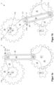
- Figure 1 shows a transmission 2 according to a first embodiment of the invention in three operating states within the scope of its torque transmitting elements.
- the transmission 2 comprises a drive shaft 7 on which a gear 18 is arranged in a rotationally fixed manner.
- the gear 18 meshes with a gear 19 which is arranged in a rotationally fixed manner on a shaft 9.
- a crank 22 is arranged in a rotationally fixed manner on the same shaft 9.
- a driver 23 is attached to the crank 22 off-center in relation to the axis of rotation of the shaft 9 or the crank 22 in such a way that the driver 23 moves in the direction of the axis of rotation of the Shaft 9 in the example shown extends out of the plane of the sheet.
- the driver 23 is therefore designed as a projection and in the example shown is circular in cross-section.
- the gear 2 has a shaft 17, the axis of rotation of which runs parallel to the axis of rotation of the shaft 9 and is arranged at a distance from the other arrangement specified above.
- An endless traction means 26, here in the form of a belt, is wound around both elements 17, 23.
- the driver 23 and the shaft 17 are mounted in a web 24 via a respective bearing 4 so that they can rotate freely.
- the web 24 has the function of ensuring the distance between the elements 17, 23, and thus also serves as a spacer.
- a gear 21 is arranged on the shaft 17 in a rotationally fixed manner and meshes with a gear 20.
- the gear 20 is arranged in a rotationally fixed manner on an output shaft 8 of the transmission 2, on which an output gear 11 of the transmission 2 is additionally arranged.
- Both gears 20, 21 are connected via a respective Figure 1 concealed bearing 4 is freely rotatably received in a web 25.
- the web 25 has the same function in relation to the elements 20, 21 as the web 24 has in relation to the elements 17, 23.
- Both webs 24, 25 are arranged in a pivot joint relative to one another, with the axis of rotation of the pivot joint coinciding with the axis of rotation of the shaft 17.
- FIG. 1a A radial straight line is shown as a solid line on the elements 11 and 21. These straight lines represent rotational positions of the respective wheel 11, 21 in the Figure 1a shown operating position and accordingly form rotational position markings 11a and 21a.
- the shaft 17 and the gear 21 have accordingly also completed half a rotation in the clockwise direction, as illustrated by a rotational position marking 21b.
- Figure 1c shows the gear 2 in an operating position after the gear 19 has been rotated by a further 180°, i.e. opposite Figure 1a has completed a full clockwise rotation.
- the crank 22 and the driver 23 have also completed a second half rotation, so that the elements 17 and 21 have also completed this second half rotation.
- all the elements 17, 19, 21 - 23 reach the Figure 1a rotation position shown.
- the angle of rotation ⁇ is significantly larger than the angle of rotation ⁇ , which results in the desired, discrete rotation of the output gear 11.
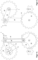
- FIG. 2 shows the gearbox 2 of Figure 1a from the back, which is not visible there.
- a second bridge 25 which is provided here for stability reasons. Of course, only one bridge 25 could be provided in total.
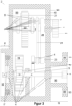
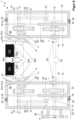
- Figure 3 shows the gearbox 2 in the Figure 1a shown operating position, designed with a housing 90, in section.
- the housing 90 has a wall section 40, which in the example shown serves to support the shafts 7 - 9.
- the drive wheel (gear) 18 is accommodated via the shaft 7 in a freely rotatable manner, for example in two opposing, here vertically running outer walls of the wall section 40 by means of a respective bearing 4.
- the shaft 7 is thus accessible from both opposing outer sides of the housing 90.
- the shaft 7 has an engagement projection 5, which is preferably designed to complement an engagement recess 6 that is formed at the right end of the shaft 7.
- This makes it possible to attach several gears 2 to one another, with the engagement projection 5 of one gear 2 coming into rotational engagement with the engagement recess 6 of the other gear 2.
- This makes it possible to drive several gears 2 with just one drive element (motor).
- this enables the formation of a standard gear that can be produced in large quantities and thus relatively inexpensively. Last but not least, assembly is made easier because it is not possible to incorrectly assemble several gears 2.
- the shaft 9, on which the gear 19 and the crank 22 are arranged in a rotationally fixed manner, is again mounted at both ends via bearings 4 in the left outer wall and advantageously in an intermediate wall 42 in the interior 99 so that it can rotate freely. If the stability is sufficient, a bearing 4 and/or the intermediate wall 42 can also be omitted.
- the gear 21 is arranged on the shaft 17 in a rotationally fixed manner.
- the bearings 4, via which the webs 25 accommodate the shafts 8, 17 in a freely rotatable manner, can be seen.
- the shaft 8 in turn, is advantageously accommodated in a manner analogous to the shaft 7 in the aforementioned two vertically extending outer walls of the wall section 40 by means of a respective bearing 4.
- the shaft 8 protrudes here to the right from the housing 90.
- the output gear 11 of the gear 2 is attached in a rotationally fixed manner to the free end of the shaft 8 pointing to the right.
- the output gear 11 serves to connect the gear 2 to the roller(s) to be driven, for example in the form of tear-off rollers 80b of a combing station of a combing machine, described in more detail later.
- the housing 90 has a projection 91 on the left part of the wall section 40, which has a recess 95 inside in which the engagement projection 5 is arranged.
- the projection 91 protects the engagement projection 5 from external mechanical influences.
- the housing 90 has another projection 92 on the right-hand part of the wall section 40, which is opposite the projection 91.
- the projection 92 is preferably designed to complement the inner contour of the recess 95. This makes it possible to attach two housings 90 to one another in such a way that the housings 90, 90 can be mounted in a rotationally secure manner relative to one another.
- the projection 91 has screw openings 97 which, viewed along the axis of rotation of the shafts 7 - 9, are aligned with through openings 98 which are formed in upward and downward extending projections 93, 93 on the projection 92.
- the projection 92 comprises a recess 96 inside, in which the shaft 7 with the engagement recess 6 is preferably again mechanically protected.
- the projection 91 and the recess 96 are preferably designed to be able to be pushed into one another in a form-fitting and/or force-fitting manner, which simplifies the preferably twist-proof assembly.
- Figure 4 shows a drive arrangement 1 with two gears 2.
- the housings 90, 90 of the two gears 2, 2 are fixed to one another by inserting the projection 92 of the left housing 90 into the recess 95 (not visible here) of the projection 91 of the right housing 90 and screwing the corresponding screws 3 through the through openings 98 of the left housing 90 (not visible here) into the screw openings 97 of the right housing 90 (also not visible here).
- a motor 50 is attached to the left housing 90 by means of a projection 51 that is preferably similar to the projection 91.
- the drive shaft of the motor 50 which is not visible, preferably engages around the engagement projection 5 of the left gear 2, so that the motor 50 can set the shaft 7 of the left gear 2 in rotation.
- This structure makes it possible to attach the entire drive arrangement to the frame of a combing machine, for example.
- the design enables the formation of standardized gears 2, which helps to keep manufacturing costs low.
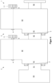
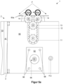
- Figure 5 shows in two views a modification of the gear 2 in a drive arrangement 1 with tear-off rollers 80a, 80b as part of a combing machine.
- the housing 90 of the respective transmission 2 has Figure 5a left side has a projection-like wall section 41 which serves for fastening to a frame wall 10 of a combing machine (not shown in more detail) by means of screws 3.
- the housing 90 is in Figure 5a from the in Figure 3 right side of the gear 2.
- the projection 92 can therefore be seen. It can also be seen that the projection 92 has four through holes 98 as an example.
- the preferably centrally arranged recess 96 can be seen, in the interior of which the end of the shaft 7 (not visible here) with the engagement recess 6 can be seen.
- the output gear 11 can be seen, which is arranged on the shaft 8 in a rotationally fixed manner.
- the output wheel 11 is rotationally connected via a belt 12 to a drive wheel 13 of a tear-off roller arrangement.
- the drive wheel 13 is arranged on a shaft 15 in a rotationally fixed manner or is formed in one piece with it. Behind this arrangement is the arrangement of tear-off rollers 80a and a first pinion 14, which is arranged on a shaft 16 in a rotationally fixed manner.
- the first pinion 14 meshes either with the drive wheel 13 itself or with a second pinion arranged behind it, which is not visible.
- the tear-off rollers 80a, 80b have a respective guide section 83a, 83b in the form of the peripheral surface there for transporting a respective fiber band F.
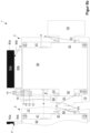
- Figure 5b shows the arrangement 1 of two gears 2, 2 each according to Figure 5a and with an engine 50, wherein the gears 2, 2 are driven by the Figure 5a shown from the right side.
- Both gears 2, 2 are attached to one and the same frame wall 10, here of a combing machine not shown in any further detail, using three screws 3 each.
- the housings 90, 90 of two immediately adjacent gears 2, 2 are therefore not attached to one another. Rather, there is a tubular connecting element 60 between the two housings 90, 90.
- the connecting element 60 has a projection 61 at its right end.
- the projection 61 is preferably designed analogously to the projection 91 of the respective housing 90. This means that the respective right-hand adjacent housing 90 is screwed to the projection 61 by means of screws 3 via the projection 92.
- the connecting element 60 has a projection 62, which is preferably designed analogously to the projection 92 of the housing 90 and is thus inserted into the projection 91 of the adjacent housing 90 and is also fastened there by means of screws 3.
- the connecting element 60 In the interior of the connecting element 60 there is a shaft 63 which is rotationally connected to the shafts 7, 7 (not visible here) of the two adjacent gears 2, 2. Since the connecting element 60 takes over the fastening, a plug connection between the shaft 63 and the associated shafts 7, 7 is sufficient.
- a right tear-off roller mechanism can be seen in particular on the right gear 2, which is rotationally connected via the belt 12 to the associated driven wheel 11 of the right gear 2, which is covered by the belt 12.
- the drive wheel 13 of the right mechanism is also covered by the belt 12.
- To the right of the drive wheel 13 is the shaft 15, on which an exemplary Figure 5a pinion 14 hidden from the drive wheel 13.
- the drive wheel 13 has a depth that is greater than the width of the belt 12, so that the Figure 5a visible pinion 14 can mesh with the drive wheel 13.
- a lower tear-off roller 80b is mounted or attached to each shaft 15, 16 in a rotationally fixed manner.
- the fiber band F is guided between an upper tear-off roller 80a and an associated lower tear-off roller 80b in a known manner, so that the description of the functioning of the tear-off rollers 80a, 80b is omitted.
- the drive mechanism between the Figure 5a left pinion 14 and the right pinion 14 or drive wheel 15 and the lower tear-off rollers 80b arranged thereon in a rotationally fixed manner in conjunction with two upper tear-off rollers 80a is known and is therefore also not explained in more detail.
- the left gear 2 also operates a combing point or a tear-off roller mechanism.
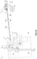
- Figure 6a also shows an arrangement 1 with two modified gears 2.
- the front gear 2 is shown in the interior 99 of an undesignated housing shell of a modified housing 90.
- the arrangement 1 comprises two continuous tear-off roller arrangements, in which a respective bearing section 84b is provided between two immediately adjacent tear-off rollers 80b.
- the bearing sections 84b serve in a known manner to support and prevent the tear-off roller arrangement from bending.
- only one front and rear pair of immediately adjacent tear-off rollers 80b, 80b and of immediately adjacent bearing sections 84b, 84b are shown. each provided with reference numerals.
- the upper tear-off rollers 80a are not shown.
- the shaft 17 of the front gear 2 is rotatably mounted in a cover 46 via a non-visible bearing, which is shown here as being open at the front, but is actually designed like a lid.
- Each traction device 26 of both gears 2 is wound around a deflection roller 17a arranged on the shaft 17 in a rotationally fixed manner.
- the cover 46 itself is rotatably mounted on a housing section 45. This enables the shaft 17 to move relative to the housing 90.
- the drive shaft 7 can also be seen.
- the shaft 8 is rotatably mounted in the housing 90 (not shown) via an associated bearing 4.
- the associated driver 23 is not attached to the crank 22 but to a disk 47a arranged on the outside of the housing 90.
- Each disk 47a is screwed to an associated disk 47b, which is only visible on the rear gear and is arranged in a rotationally fixed manner on the associated shaft 9.
- the shaft 9 on the rear gear is only shown as a stub. However, it is clear that it extends further in the direction of the front gear 2 into the interior of the housing 90 (not shown) in order to accommodate the associated crank 22 in a rotationally fixed manner.
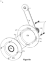
- Figure 6b shows a partial exploded view of the disc 47b of the Figure 6a rear transmission 2.
- the disk 47a has four arcuate slots 47c on its circumference.
- the disk 47b has four screw holes 47d that are open towards the disk 47a and are preferably continuous.
- the arrangement of the slots 47c and the Screw openings 47d are such that screws 3 are screwed from the side of the disk 47a facing away from the disk 47b through its elongated holes 47c into an associated screw opening 47d or, as shown here, are screwed through these with nuts 30 and thus fix the disk 47a to the disk 47b.
- the disc 47a has an inner cone 47i inside, into which the disc 47b is inserted with a corresponding, non-visible outer cone, which is such that the axes of rotation of the discs 47a, 47b coincide.
- an engagement section is preferably formed on the disk 47a, for example in the form of a projection with an external hexagon formed in the direction of a deflection roller 17a. This makes it possible to rotate the disk 47a with a conventional tool (here, for example, a wrench) after the screws 3 have been loosened.
- This design allows the soldering time to be adjusted if the gear 2 is used to drive tear-off rollers 80b.
- the adjustment of the disk 47b indirectly results in an adjustment of the rotational position relative to the drive shaft 7.
- a marking 47f in the form of a The side edge of the disc 47a is arranged along the rotation axis of the disc 47a, an elongated and black bar.
- a scale 47g with two groups of five straight line markings each running along the rotation axis of the disc 47a and an elongated bar with a black border arranged between them, also running along the rotation axis of the disc 47a.
- the bars of the marking 47f and the scale 47g are preferably on one and the same line.
- the marking 47f "moving" An adjustment of the soldering time earlier or later in relation to the basic setting is therefore visualized by the marking 47f "moving" to the respective group of line markings.
- the discs 47a, 47b preferably have the same outer diameter. Last but not least, this design makes it easy to find the basic setting again.
- Figure 7 shows a transmission 2 according to a second embodiment of the invention in a view analogous to Figure 1a .
- the transmission 2 differs from the first embodiment in that the Figure 1a front web 25 is replaced by a circular disk 27.
- the (partially) concealed elements are shown by dashed lines.
- Figure 8 shows two gearboxes 2 each according to Figure 7 and with a respective housing 90 in a tear-off roller arrangement 1 of a combing machine.
- All torque-transmitting gear elements are housed in a respective housing 90 and are thus mechanically and lubricatingly protected from the outside.
- the torque-transmitting gear elements of both Gearbox 2 are in Figure 8 with respect to the two housings 90, they are mirror-symmetrical to one another along a vertical line along the plane of the page and in the vertical direction to this plane of the page.
- the disk 27 of the respective gear 2 is accommodated in the housing 90 via a labyrinth seal 29 so that it can rotate freely.
- the labyrinth seal 29 means that the gears 18 - 21 of the respective gear 2 are hermetically sealed against the crank drive with belt 26.
- the arrangement with crank 22, belt drive and web 24 is therefore arranged outside the space in which the gears 18 - 21 of the respective gear 2 are arranged.
- a respective cover 70 is placed on each wall section 40. In the example shown, this is done by means of locking projections 72 which engage in a corresponding locking recess 44 of the wall section 98. Seals 28 are preferably provided between the cover 70 and the wall section 40.
- the cover 70 of the left gear 2 has the projection 92 specified above.
- the shaft 7 is designed in two parts here.
- a first shaft section 7b which receives the gear 18 and the crank 22 in a rotationally fixed manner, engages with its end facing away from the shaft 63 in a force-fitting and/or form-fitting manner in a shaft section 7a and is thus rotationally connected thereto.
- the shaft section 7a again has, by way of example, an engagement recess 6 at its end facing away from the shaft 63. This makes it possible to remove the cover 70 by overcoming the locking connection, for example to replace a worn belt 26. If the cover 70 is put back on, the shaft sections 7a, 7b come into rotational engagement with one another again.
- the cover 70 of the right gear 2 does not have such a projection 92. Therefore, the shaft section 7b is also missing here. This means that apart from the cover 70 and the shaft section 7a, the two gears 2 do not differ from one another. This increases the number of identical parts with which the two gears 2, 2 can be realized.
- the tear-off rollers 80a, 80b form guide sections 83a, 83b with their outer circumference, between which fiber band F is guided.
- the tear-off rollers 80a, 80b are accommodated in the wall sections 40 of both housings 90 via axle sections 81a and 81b in a freely rotatable manner.
- Shaft sections 82a, 82b are located between the guide sections 83a, 83b and the associated axle sections 81a, 81b.
- Figure 9 shows the arrangement 1 of Figure 8 with closed housings 90 and motor 50 mounted on the left gearbox 2.
- Figure 10 shows a modification of the Figure 8 left transmission 2. It can be seen that all torque-transmitting elements, including crank 22 and belt drive, are accommodated in the housing 90, so that it has only a single interior space 99.
- the cover 70 is formed here by means of a plate-like part, which is attached to the wall section 40 via screws 3 via screw openings 43.
- the screw openings 43 are formed, for example, in a respective projection 94 of the wall section 40.
- the cover 70 is so designed in such a way that it does not accommodate the shaft 8. Unscrewing the cover 70 makes the belt drive accessible, for example to replace the belt 26.
- This embodiment has the advantage that the housing 90 can remain very simple. This solution is possible because lubricating oil or grease for lubricating the moving parts cannot escape to the outside.
- the cover 70 and the wall section 40 have projections 71 and 41, respectively, which are designed in such a way that the cover 70 is flush with the wall section 40 surrounding it.
- the invention is not limited to the embodiments described above.
- the gears shown can be partially exchanged or combined with one another. This also applies to the options given below.
- the driver 23 and/or the shaft 17 and the belt 26 can be designed as any type of traction drive, for example with a toothed belt, cable and the like.
- a traction tensioner can be provided. This can be implemented, for example, by guiding one of the bearings 4 in an elongated hole in the web 24, which extends along a connecting line between the centers of rotation of the elements 17, 23. The respective bearing 4 is pushed away from the other bearing 4 arranged in the web 24 by a tensioning element such as a compression spring.
- the pinion 20, 21 and the traction drive 17, 23, 26 can be exchanged for one another.
- the pinion 20, 21 can be replaced by any other drive for torque transmission, such as a traction drive or friction wheel drive.
- the number, shape, size and arrangement of the teeth of gears 18 - 20 can vary.
- the gear teeth can also be different from one another.
- the pitch curves of the gears 18 - 20 can be designed in such a way that their pitch curves change their distance from the center of rotation of the respective associated shaft 7 - 9, 17 over time. This can be done, for example, by means of a non-circular pitch curve.
- the respective pitch curve can be circular, with the center of the associated circle lying outside the center of rotation of the respective gear 18 - 20, i.e. is arranged eccentrically.
- the pitch curves can also be designed in a different way in order to make the transmission ratio between the drive shaft 7 and the output shaft 8 variable.
- the distance of the pitch curve of the gear 19 advantageously increases at first and then decreases again towards the end.
- the transmission ratio to the gear 18 is preferably 1:1. This results in an initially accelerated, then possibly constant and then decelerated movement of the output shaft 8.
- the number, shape, size and arrangement of the teeth of the gears 18 - 21 can vary. Pauses can also be provided between the transitions of the rotation of the output shaft 8 in opposite directions.
- the sum of the two angles of rotation ⁇ , ⁇ can be less than 360° depending on the design of the gear 2.
- the ratio of these two angles of rotation ⁇ , ⁇ to each other can also be designed differently.
- any other shaft 7, 16 can be designed to be rotationally connected to a corresponding shaft 7, 16 of another transmission 2. In this case, some elements could be omitted in some transmissions.
- the gear 19 and the crank 22 could be formed in one piece by forming or attaching the driver 23 directly to the gear 19.
- the right end of the shaft 9 is such that the elements 4, 24, 26 attached to the driver 23 can be moved past freely.
- the shaft 7 and the gears 18, 19 can be omitted.
- the shaft 9 would then become the drive shaft of the gear 2.
- Any spinning machine having a pilger step mechanism can be equipped with the gear 2 according to the invention or an arrangement 1 that can be formed therewith.
- Such a machine can also have several arrangements 1. This allows complete drive modules to be manufactured cost-effectively, which only need to be installed.
- the tear-off roller arrangements 80b, 84b do not have to be continuous. They can also be split in the middle, for example, so that both gears 2, 2 are only operatively connected to one another via the shaft 63.
- a step rotation with a forward delivery angle of 926.5° and a reverse delivery angle of 204.7° can be achieved on the tear-off rollers 80b, resulting in an effective conveying rotation angle of the tear-off rollers 80b of 121.8°.
- the web 24 could be designed like a telescope and thus be adjustable in length by the operator.
- the soldering time can be changed during operation by using a motorized adjustment instead of the screw flange adjustment shown.
- a drive that acts directly on shaft 7 can be provided. This drive would perform a uniform drive movement at exactly the same speed as motor 50. The soldering time could be changed simply by adjusting the phase shift between this drive and motor 50. A non-uniform speed of this drive makes it possible to influence the transfer function.
- Each gear 2 can also be a part of a larger gear that also drives other elements.
- a driving gear could also be provided, for example to drive the upper grippers of the combing point(s).
- the adjustment mechanism shown can also be designed differently.
- the number of screw openings 47d and elongated holes 47c can vary.
- the disk 47b has a projection which projects from the disk 47a through an associated elongated hole 47c in the direction of the web 24.
- the disk 47a also has a projection in the area (preferably at one of its ends) which projects from the disk 47a in the direction of the web 24.
- an adjusting screw is fixed in place and freely rotatable about an axis transverse to the protrusion direction of this one projection.
- the other projection has a screw thread inside into which the adjusting screw is screwed. At least one of these two projections is arranged so that it can rotate freely parallel to the axis of rotation of the disks 47a, 47b. This makes it possible to turn the adjusting screw and thus adjust the relative positions of the disks 47a, 47b around their common axis of rotation.
- a lock nut could be provided to fix the final adjustment position.
- screw 3 must be loosened. The adjustment is accomplished by turning the adjusting screw. In a final step, the loosened screw 3 only has to be tightened again.
- the marking 47f and the scale 47g can be placed on the other disk 47a or 47b. The same applies to the design of the openings 47d and elongated holes 47c.
- the invention offers a simple and energy-saving way to realize a vocational step movement by rotating a drive shaft 7 in one and the same direction of rotation, with a simple and cost-effective structure.
Landscapes
- Engineering & Computer Science (AREA)
- General Engineering & Computer Science (AREA)
- Mechanical Engineering (AREA)
- Textile Engineering (AREA)
- Preliminary Treatment Of Fibers (AREA)
- Gear Transmission (AREA)
- Retarders (AREA)
Claims (9)
- Engrenage (2),• comprenant- un arbre de commande (7),- un arbre de sortie (8) et- une partie de transmission avec• un premier élément d'engrenage (17), lequel est, en tant que partie d'un premier niveau d'engrenage, relié fonctionnellement en rotation à l'arbre de commande (7) et• un deuxième élément d'engrenage (21) différent du premier élément d'engrenage (17) qui,∘ en tant que partie d'un deuxième niveau d'engrenage, est relié fonctionnellement en rotation à l'arbre de sortie (8) et∘ également relié fonctionnellement en rotation au premier élément d'engrenage (17), et• conçu de sorte qu'une rotation motrice de l'arbre de commande (7) dans un sens de rotation d'entrée prédéfini- autour d'un premier angle de rotation d'entrée provoque une rotation de l'arbre de sortie (8) dans un premier sens de rotation de sortie autour d'un premier angle de rotation de sortie (α) et- provoque ensuite, autour d'un deuxième angle de rotation d'entrée, une rotation de l'arbre de sortie (8) dans un deuxième sens de rotation de sortie inversé par rapport au premier sens de rotation de sortie autour d'un deuxième angle de rotation de sortie (β),• les angles de rotation de sortie (α, β) étant différents, la partie de transmission présentant un élément d'engrenage (19) qui• est relié fonctionnellement en rotation à l'arbre de commande (7), et• comprend un entraîneur (23) qui- est à distance d'un axe de rotation de l'élément d'engrenage (19),- est placé solidaire en rotation par rapport à l'élément d'engrenage (19) et- forme une partie du premier niveau d'engrenage, caractérisé en ce que l'entraîneur- présente ou forme un troisième élément d'engrenage (23), qui∘ est relié fonctionnellement en rotation au premier élément d'engrenage (17) à l'aide d'un élément de transmission (26) et∘ est placé à une distance fixe par rapport au premier élément d'engrenage (17), et en ce que, à des fins de liaison fonctionnelle indirecte en rotation, les éléments d'engrenage (17, 23) du niveau d'engrenage associé sont formés de poulies de renvoi (17, 23) autour desquelles est enroulé un moyen de transmission sans fin (26).
- Engrenage (2) selon la revendication 1, comprenant en outre un dispositif de réglage (3, 47a - 47d) conçu pour modifier une position de rotation de l'entraîneur (23) par rapport à l'arbre de commande (7).
- Engrenage (2) selon l'une des revendications précédentes, la partie de transmission comprenant un quatrième élément d'engrenage (20), lequel• est relié fonctionnellement en rotation à l'arbre de sortie (8),• forme une partie du deuxième niveau d'engrenage et• est relié fonctionnellement en rotation au deuxième élément d'engrenage (21) directement ou via un deuxième élément de transmission.
- Engrenage (2) selon l'une des revendications précédentes, les éléments d'engrenage (19-20) du niveau d'engrenage associé étant formés par des roues dentées (19 - 20) qui s'engrènent l'une dans l'autre par paire, dans le cas d'une liaison directe fonctionnelle en rotation.
- Engrenage (2) selon l'une des revendications précédentes,• le moyen de transmission (26) étant formé par une courroie (26), un câble ou une chaîne et• et les éléments d'engrenage (17, 23) associés étant des poulies de renvoi ou en comprenant.
- Système comprenant deux engrenages (2),• formés respectivement selon l'une des revendications précédentes et• conçus- pour être placés de façon attenante, de sorte que les deux engrenages (2) soient simultanément reliés ensemble selon une technique d'entraînement, et/ou- pour être placés, de sorte que leurs arbres de commande (7, 7) soient reliés fonctionnellement en rotation entre eux via un arbre (63).
- Configuration (1), comprenant• au moins un engrenage (2) formé selon l'une des revendications 1 à 5, et• une partie de commande laquelle est, côté sortie, reliée fonctionnellement en rotation à l'un au moins d'un engrenage (2) associé.
- Machine de cardage, comprenant• au moins une paire de rouleaux (80) de rouleaux (80) interagissant entre eux sur le plan d'un transport de fibres et• une configuration (1) selon la revendication 7, l'arbre de sortie (8) d'un engrenage (2) étant en liaison fonctionnelle en rotation avec un rouleau (80) de l'une au moins d'une paire de rouleaux (80) associée.
- Machine de cardage selon la revendication 8,• conçue comme peigneuse,• les rouleaux (80) d'au moins une paire de rouleaux forment des rouleaux arracheurs (80).
Applications Claiming Priority (2)
| Application Number | Priority Date | Filing Date | Title |
|---|---|---|---|
| DE102020110386.7A DE102020110386A1 (de) | 2020-04-16 | 2020-04-16 | Getriebe, Antriebsanordnung und Spinnereimaschine |
| PCT/EP2021/054802 WO2021209184A1 (fr) | 2020-04-16 | 2021-02-26 | Transmission, ensemble d'entraînement et métier à filer |
Publications (2)
| Publication Number | Publication Date |
|---|---|
| EP4136366A1 EP4136366A1 (fr) | 2023-02-22 |
| EP4136366B1 true EP4136366B1 (fr) | 2024-10-23 |
Family
ID=74844893
Family Applications (1)
| Application Number | Title | Priority Date | Filing Date |
|---|---|---|---|
| EP21708967.1A Active EP4136366B1 (fr) | 2020-04-16 | 2021-02-26 | Transmission, ensemble d'entraînement et métier à filer |
Country Status (4)
| Country | Link |
|---|---|
| EP (1) | EP4136366B1 (fr) |
| CN (1) | CN115398123B (fr) |
| DE (1) | DE102020110386A1 (fr) |
| WO (1) | WO2021209184A1 (fr) |
Families Citing this family (1)
| Publication number | Priority date | Publication date | Assignee | Title |
|---|---|---|---|---|
| CN120385747B (zh) * | 2025-06-30 | 2025-09-12 | 浙江衡昇科技有限公司 | 一种水电站检测机器人的焊缝扫查装置及其工作方法 |
Family Cites Families (8)
| Publication number | Priority date | Publication date | Assignee | Title |
|---|---|---|---|---|
| KR790001580B1 (ko) * | 1975-07-15 | 1979-11-05 | 곤다 게이지 | 섬유코밍 기계내의 디탯칭롤러의 구동장치 |
| DE19612808A1 (de) * | 1996-04-02 | 1997-10-09 | Cetex Chemnitzer Textilmaschin | Antriebsvorrichtung für die Abreißwalzen einer Kämmaschine |
| DE102006020589B4 (de) * | 2006-05-02 | 2010-06-02 | Oerlikon Textile Gmbh & Co. Kg | Antriebswelle für die Speisewalzen einer Kämmmaschine |
| EP2108721A1 (fr) * | 2008-04-08 | 2009-10-14 | Maschinenfabrik Rieter Ag | Entraînement pour cylindres d'arrachage d'une peigneuse |
| JP5609530B2 (ja) * | 2010-10-22 | 2014-10-22 | 株式会社豊田自動織機 | コーマのデタッチングローラ動作設定装置 |
| DE102012011030A1 (de) * | 2012-06-05 | 2013-12-05 | Trützschler GmbH & Co Kommanditgesellschaft | Vorrichtung an einer Kämmmaschine mit einer Antriebsvorrichtung zur Erzeugung einer Pilgerschrittbewegung für die Abreißwalzen |
| CH711289A2 (de) * | 2015-07-03 | 2017-01-13 | Rieter Ag Maschf | Kämmmaschine. |
| CH714584A2 (de) * | 2018-01-23 | 2019-07-31 | Rieter Ag Maschf | Getriebe mit einer Einstellvorrichtung für eine Pilgerschrittbewegung für eine Kämmmaschine. |
-
2020
- 2020-04-16 DE DE102020110386.7A patent/DE102020110386A1/de active Pending
-
2021
- 2021-02-26 EP EP21708967.1A patent/EP4136366B1/fr active Active
- 2021-02-26 WO PCT/EP2021/054802 patent/WO2021209184A1/fr not_active Ceased
- 2021-02-26 CN CN202180028899.6A patent/CN115398123B/zh active Active
Also Published As
| Publication number | Publication date |
|---|---|
| DE102020110386A1 (de) | 2021-10-21 |
| EP4136366A1 (fr) | 2023-02-22 |
| WO2021209184A1 (fr) | 2021-10-21 |
| CN115398123B (zh) | 2025-10-28 |
| CN115398123A (zh) | 2022-11-25 |
Similar Documents
| Publication | Publication Date | Title |
|---|---|---|
| EP3612402B1 (fr) | Transmission de véhicule, en particulier pour hybride série-parallel | |
| DE102017205721B4 (de) | Getriebeeinheit für ein Kraftfahrzeug | |
| EP3700799A1 (fr) | Colonne de direction pour véhicule automobile | |
| WO2022156944A1 (fr) | Groupe motopropulseur pour un véhicule automobile | |
| EP1574316B1 (fr) | Transmission pour extrudeuse à deux vis | |
| DE102004005869A1 (de) | Antriebseinheit, insbesondere Einrad-Triebwerk für ein batteriebetriebenes Fahrzeug | |
| EP3131382B1 (fr) | Entraînement de lame de faucheuse | |
| DE4393468C2 (de) | Getriebeanordung für einen zweiachsigen Extruder | |
| DE3444420A1 (de) | Vorrichtung zur erzeugung von schwenkbewegungen | |
| EP4136366B1 (fr) | Transmission, ensemble d'entraînement et métier à filer | |
| DE3401628C2 (de) | Antrieb für Kraftfahrzeuge | |
| WO2020120277A1 (fr) | Essieu rigide entraîné par moteur électrique, destiné à des véhicules, en particulier des véhicules utilitaires, et procédé de fonctionnement correspondant, produit programme d'ordinateur, dispositif de commande et/ou de régulation et véhicule automobile | |
| DE102004023151B4 (de) | Umlaufgetriebe | |
| EP1948420B1 (fr) | Transmission pour extrudeuse a double vis | |
| DE69727469T2 (de) | Stufenloses getriebe für fahrzeuge und rasenmäher mit einem solchen getriebe | |
| EP0999032B1 (fr) | Transmission pour extrudeuse à deux vis | |
| DE3941719A1 (de) | Umlaufgetriebe | |
| DD294763A5 (de) | Getriebe | |
| DE19538761A1 (de) | Drehmomentverzweigendes Getriebe | |
| DE102016103197A1 (de) | Riemengetriebe und lenksystem | |
| EP4074898B1 (fr) | Excavatrice à fraises et procédé de changement de la largeur de la fraise | |
| EP1078178A1 (fr) | Transmission a roue dentee excentrique | |
| AT505628B1 (de) | Getriebe zur umkehrspielfreien kraftübertragung | |
| EP0855317B1 (fr) | Dispositif d'entraínement, en particulier pour essuie-glace de véhicule automobile | |
| DE69324172T2 (de) | Getriebevorrichtung |
Legal Events
| Date | Code | Title | Description |
|---|---|---|---|
| STAA | Information on the status of an ep patent application or granted ep patent |
Free format text: STATUS: UNKNOWN |
|
| STAA | Information on the status of an ep patent application or granted ep patent |
Free format text: STATUS: THE INTERNATIONAL PUBLICATION HAS BEEN MADE |
|
| PUAI | Public reference made under article 153(3) epc to a published international application that has entered the european phase |
Free format text: ORIGINAL CODE: 0009012 |
|
| STAA | Information on the status of an ep patent application or granted ep patent |
Free format text: STATUS: REQUEST FOR EXAMINATION WAS MADE |
|
| 17P | Request for examination filed |
Effective date: 20221116 |
|
| AK | Designated contracting states |
Kind code of ref document: A1 Designated state(s): AL AT BE BG CH CY CZ DE DK EE ES FI FR GB GR HR HU IE IS IT LI LT LU LV MC MK MT NL NO PL PT RO RS SE SI SK SM TR |
|
| DAV | Request for validation of the european patent (deleted) | ||
| DAX | Request for extension of the european patent (deleted) | ||
| P01 | Opt-out of the competence of the unified patent court (upc) registered |
Effective date: 20230622 |
|
| GRAP | Despatch of communication of intention to grant a patent |
Free format text: ORIGINAL CODE: EPIDOSNIGR1 |
|
| STAA | Information on the status of an ep patent application or granted ep patent |
Free format text: STATUS: GRANT OF PATENT IS INTENDED |
|
| INTG | Intention to grant announced |
Effective date: 20240702 |
|
| GRAS | Grant fee paid |
Free format text: ORIGINAL CODE: EPIDOSNIGR3 |
|
| GRAA | (expected) grant |
Free format text: ORIGINAL CODE: 0009210 |
|
| STAA | Information on the status of an ep patent application or granted ep patent |
Free format text: STATUS: THE PATENT HAS BEEN GRANTED |
|
| AK | Designated contracting states |
Kind code of ref document: B1 Designated state(s): AL AT BE BG CH CY CZ DE DK EE ES FI FR GB GR HR HU IE IS IT LI LT LU LV MC MK MT NL NO PL PT RO RS SE SI SK SM TR |
|
| REG | Reference to a national code |
Ref country code: GB Ref legal event code: FG4D Free format text: NOT ENGLISH |
|
| REG | Reference to a national code |
Ref country code: CH Ref legal event code: EP |
|
| REG | Reference to a national code |
Ref country code: DE Ref legal event code: R096 Ref document number: 502021005567 Country of ref document: DE |
|
| REG | Reference to a national code |
Ref country code: IE Ref legal event code: FG4D Free format text: LANGUAGE OF EP DOCUMENT: GERMAN |
|
| REG | Reference to a national code |
Ref country code: LT Ref legal event code: MG9D |
|
| REG | Reference to a national code |
Ref country code: NL Ref legal event code: MP Effective date: 20241023 |
|
| PG25 | Lapsed in a contracting state [announced via postgrant information from national office to epo] |
Ref country code: NL Free format text: LAPSE BECAUSE OF FAILURE TO SUBMIT A TRANSLATION OF THE DESCRIPTION OR TO PAY THE FEE WITHIN THE PRESCRIBED TIME-LIMIT Effective date: 20241023 |
|
| PG25 | Lapsed in a contracting state [announced via postgrant information from national office to epo] |
Ref country code: NL Free format text: LAPSE BECAUSE OF FAILURE TO SUBMIT A TRANSLATION OF THE DESCRIPTION OR TO PAY THE FEE WITHIN THE PRESCRIBED TIME-LIMIT Effective date: 20241023 |
|
| PG25 | Lapsed in a contracting state [announced via postgrant information from national office to epo] |
Ref country code: HR Free format text: LAPSE BECAUSE OF FAILURE TO SUBMIT A TRANSLATION OF THE DESCRIPTION OR TO PAY THE FEE WITHIN THE PRESCRIBED TIME-LIMIT Effective date: 20241023 Ref country code: PT Free format text: LAPSE BECAUSE OF FAILURE TO SUBMIT A TRANSLATION OF THE DESCRIPTION OR TO PAY THE FEE WITHIN THE PRESCRIBED TIME-LIMIT Effective date: 20250224 Ref country code: IS Free format text: LAPSE BECAUSE OF FAILURE TO SUBMIT A TRANSLATION OF THE DESCRIPTION OR TO PAY THE FEE WITHIN THE PRESCRIBED TIME-LIMIT Effective date: 20250223 |
|
| PGFP | Annual fee paid to national office [announced via postgrant information from national office to epo] |
Ref country code: DE Payment date: 20250218 Year of fee payment: 5 |
|
| PG25 | Lapsed in a contracting state [announced via postgrant information from national office to epo] |
Ref country code: FI Free format text: LAPSE BECAUSE OF FAILURE TO SUBMIT A TRANSLATION OF THE DESCRIPTION OR TO PAY THE FEE WITHIN THE PRESCRIBED TIME-LIMIT Effective date: 20241023 |
|
| PG25 | Lapsed in a contracting state [announced via postgrant information from national office to epo] |
Ref country code: BG Free format text: LAPSE BECAUSE OF FAILURE TO SUBMIT A TRANSLATION OF THE DESCRIPTION OR TO PAY THE FEE WITHIN THE PRESCRIBED TIME-LIMIT Effective date: 20241023 |
|
| PG25 | Lapsed in a contracting state [announced via postgrant information from national office to epo] |
Ref country code: ES Free format text: LAPSE BECAUSE OF FAILURE TO SUBMIT A TRANSLATION OF THE DESCRIPTION OR TO PAY THE FEE WITHIN THE PRESCRIBED TIME-LIMIT Effective date: 20241023 |
|
| PG25 | Lapsed in a contracting state [announced via postgrant information from national office to epo] |
Ref country code: NO Free format text: LAPSE BECAUSE OF FAILURE TO SUBMIT A TRANSLATION OF THE DESCRIPTION OR TO PAY THE FEE WITHIN THE PRESCRIBED TIME-LIMIT Effective date: 20250123 |
|
| PG25 | Lapsed in a contracting state [announced via postgrant information from national office to epo] |
Ref country code: LV Free format text: LAPSE BECAUSE OF FAILURE TO SUBMIT A TRANSLATION OF THE DESCRIPTION OR TO PAY THE FEE WITHIN THE PRESCRIBED TIME-LIMIT Effective date: 20241023 Ref country code: GR Free format text: LAPSE BECAUSE OF FAILURE TO SUBMIT A TRANSLATION OF THE DESCRIPTION OR TO PAY THE FEE WITHIN THE PRESCRIBED TIME-LIMIT Effective date: 20250124 |
|
| PGFP | Annual fee paid to national office [announced via postgrant information from national office to epo] |
Ref country code: AT Payment date: 20250417 Year of fee payment: 5 Ref country code: CH Payment date: 20250301 Year of fee payment: 5 |
|
| PG25 | Lapsed in a contracting state [announced via postgrant information from national office to epo] |
Ref country code: PL Free format text: LAPSE BECAUSE OF FAILURE TO SUBMIT A TRANSLATION OF THE DESCRIPTION OR TO PAY THE FEE WITHIN THE PRESCRIBED TIME-LIMIT Effective date: 20241023 |
|
| PGFP | Annual fee paid to national office [announced via postgrant information from national office to epo] |
Ref country code: IT Payment date: 20250224 Year of fee payment: 5 |
|
| PG25 | Lapsed in a contracting state [announced via postgrant information from national office to epo] |
Ref country code: RS Free format text: LAPSE BECAUSE OF FAILURE TO SUBMIT A TRANSLATION OF THE DESCRIPTION OR TO PAY THE FEE WITHIN THE PRESCRIBED TIME-LIMIT Effective date: 20250123 |
|
| PG25 | Lapsed in a contracting state [announced via postgrant information from national office to epo] |
Ref country code: SM Free format text: LAPSE BECAUSE OF FAILURE TO SUBMIT A TRANSLATION OF THE DESCRIPTION OR TO PAY THE FEE WITHIN THE PRESCRIBED TIME-LIMIT Effective date: 20241023 |
|
| PG25 | Lapsed in a contracting state [announced via postgrant information from national office to epo] |
Ref country code: DK Free format text: LAPSE BECAUSE OF FAILURE TO SUBMIT A TRANSLATION OF THE DESCRIPTION OR TO PAY THE FEE WITHIN THE PRESCRIBED TIME-LIMIT Effective date: 20241023 |
|
| PG25 | Lapsed in a contracting state [announced via postgrant information from national office to epo] |
Ref country code: EE Free format text: LAPSE BECAUSE OF FAILURE TO SUBMIT A TRANSLATION OF THE DESCRIPTION OR TO PAY THE FEE WITHIN THE PRESCRIBED TIME-LIMIT Effective date: 20241023 |
|
| PG25 | Lapsed in a contracting state [announced via postgrant information from national office to epo] |
Ref country code: RO Free format text: LAPSE BECAUSE OF FAILURE TO SUBMIT A TRANSLATION OF THE DESCRIPTION OR TO PAY THE FEE WITHIN THE PRESCRIBED TIME-LIMIT Effective date: 20241023 |
|
| REG | Reference to a national code |
Ref country code: DE Ref legal event code: R097 Ref document number: 502021005567 Country of ref document: DE |
|
| PG25 | Lapsed in a contracting state [announced via postgrant information from national office to epo] |
Ref country code: SK Free format text: LAPSE BECAUSE OF FAILURE TO SUBMIT A TRANSLATION OF THE DESCRIPTION OR TO PAY THE FEE WITHIN THE PRESCRIBED TIME-LIMIT Effective date: 20241023 |
|
| PG25 | Lapsed in a contracting state [announced via postgrant information from national office to epo] |
Ref country code: CZ Free format text: LAPSE BECAUSE OF FAILURE TO SUBMIT A TRANSLATION OF THE DESCRIPTION OR TO PAY THE FEE WITHIN THE PRESCRIBED TIME-LIMIT Effective date: 20241023 |
|
| PLBE | No opposition filed within time limit |
Free format text: ORIGINAL CODE: 0009261 |
|
| STAA | Information on the status of an ep patent application or granted ep patent |
Free format text: STATUS: NO OPPOSITION FILED WITHIN TIME LIMIT |
|
| PG25 | Lapsed in a contracting state [announced via postgrant information from national office to epo] |
Ref country code: SE Free format text: LAPSE BECAUSE OF FAILURE TO SUBMIT A TRANSLATION OF THE DESCRIPTION OR TO PAY THE FEE WITHIN THE PRESCRIBED TIME-LIMIT Effective date: 20241023 |
|
| PG25 | Lapsed in a contracting state [announced via postgrant information from national office to epo] |
Ref country code: MC Free format text: LAPSE BECAUSE OF FAILURE TO SUBMIT A TRANSLATION OF THE DESCRIPTION OR TO PAY THE FEE WITHIN THE PRESCRIBED TIME-LIMIT Effective date: 20241023 |
|
| 26N | No opposition filed |
Effective date: 20250724 |
|
| PG25 | Lapsed in a contracting state [announced via postgrant information from national office to epo] |
Ref country code: LU Free format text: LAPSE BECAUSE OF NON-PAYMENT OF DUE FEES Effective date: 20250226 |
|
| GBPC | Gb: european patent ceased through non-payment of renewal fee |
Effective date: 20250226 |
|
| REG | Reference to a national code |
Ref country code: BE Ref legal event code: MM Effective date: 20250228 |
|
| PG25 | Lapsed in a contracting state [announced via postgrant information from national office to epo] |
Ref country code: GB Free format text: LAPSE BECAUSE OF NON-PAYMENT OF DUE FEES Effective date: 20250226 |
|
| PG25 | Lapsed in a contracting state [announced via postgrant information from national office to epo] |
Ref country code: FR Free format text: LAPSE BECAUSE OF NON-PAYMENT OF DUE FEES Effective date: 20250228 |
|
| PG25 | Lapsed in a contracting state [announced via postgrant information from national office to epo] |
Ref country code: BE Free format text: LAPSE BECAUSE OF NON-PAYMENT OF DUE FEES Effective date: 20250228 |
|
| PG25 | Lapsed in a contracting state [announced via postgrant information from national office to epo] |
Ref country code: IE Free format text: LAPSE BECAUSE OF NON-PAYMENT OF DUE FEES Effective date: 20250226 |
|
| REG | Reference to a national code |
Ref country code: CH Ref legal event code: U11 Free format text: ST27 STATUS EVENT CODE: U-0-0-U10-U11 (AS PROVIDED BY THE NATIONAL OFFICE) Effective date: 20260301 |