EP4135169A1 - Aussenläufermotor mit einem kühlrad zur kühlung des stators - Google Patents
Aussenläufermotor mit einem kühlrad zur kühlung des stators Download PDFInfo
- Publication number
- EP4135169A1 EP4135169A1 EP22187218.7A EP22187218A EP4135169A1 EP 4135169 A1 EP4135169 A1 EP 4135169A1 EP 22187218 A EP22187218 A EP 22187218A EP 4135169 A1 EP4135169 A1 EP 4135169A1
- Authority
- EP
- European Patent Office
- Prior art keywords
- stator
- section
- cooling wheel
- cooling
- external rotor
- Prior art date
- Legal status (The legal status is an assumption and is not a legal conclusion. Google has not performed a legal analysis and makes no representation as to the accuracy of the status listed.)
- Pending
Links
Images
Classifications
-
- H—ELECTRICITY
- H02—GENERATION; CONVERSION OR DISTRIBUTION OF ELECTRIC POWER
- H02K—DYNAMO-ELECTRIC MACHINES
- H02K5/00—Casings; Enclosures; Supports
- H02K5/04—Casings or enclosures characterised by the shape, form or construction thereof
- H02K5/16—Means for supporting bearings, e.g. insulating supports or means for fitting bearings in the bearing-shields
- H02K5/173—Means for supporting bearings, e.g. insulating supports or means for fitting bearings in the bearing-shields using bearings with rolling contact, e.g. ball bearings
- H02K5/1737—Means for supporting bearings, e.g. insulating supports or means for fitting bearings in the bearing-shields using bearings with rolling contact, e.g. ball bearings radially supporting the rotor around a fixed spindle; radially supporting the rotor directly
-
- H—ELECTRICITY
- H02—GENERATION; CONVERSION OR DISTRIBUTION OF ELECTRIC POWER
- H02K—DYNAMO-ELECTRIC MACHINES
- H02K9/00—Arrangements for cooling or ventilating
- H02K9/02—Arrangements for cooling or ventilating by ambient air flowing through the machine
- H02K9/04—Arrangements for cooling or ventilating by ambient air flowing through the machine having means for generating a flow of cooling medium
- H02K9/06—Arrangements for cooling or ventilating by ambient air flowing through the machine having means for generating a flow of cooling medium with fans or impellers driven by the machine shaft
-
- H—ELECTRICITY
- H02—GENERATION; CONVERSION OR DISTRIBUTION OF ELECTRIC POWER
- H02K—DYNAMO-ELECTRIC MACHINES
- H02K1/00—Details of the magnetic circuit
- H02K1/06—Details of the magnetic circuit characterised by the shape, form or construction
- H02K1/12—Stationary parts of the magnetic circuit
- H02K1/14—Stator cores with salient poles
- H02K1/146—Stator cores with salient poles consisting of a generally annular yoke with salient poles
- H02K1/148—Sectional cores
-
- H—ELECTRICITY
- H02—GENERATION; CONVERSION OR DISTRIBUTION OF ELECTRIC POWER
- H02K—DYNAMO-ELECTRIC MACHINES
- H02K21/00—Synchronous motors having permanent magnets; Synchronous generators having permanent magnets
- H02K21/12—Synchronous motors having permanent magnets; Synchronous generators having permanent magnets with stationary armatures and rotating magnets
- H02K21/22—Synchronous motors having permanent magnets; Synchronous generators having permanent magnets with stationary armatures and rotating magnets with magnets rotating around the armatures, e.g. flywheel magnetos
-
- H—ELECTRICITY
- H02—GENERATION; CONVERSION OR DISTRIBUTION OF ELECTRIC POWER
- H02K—DYNAMO-ELECTRIC MACHINES
- H02K5/00—Casings; Enclosures; Supports
- H02K5/04—Casings or enclosures characterised by the shape, form or construction thereof
- H02K5/15—Mounting arrangements for bearing-shields or end plates
-
- H—ELECTRICITY
- H02—GENERATION; CONVERSION OR DISTRIBUTION OF ELECTRIC POWER
- H02K—DYNAMO-ELECTRIC MACHINES
- H02K9/00—Arrangements for cooling or ventilating
- H02K9/08—Arrangements for cooling or ventilating by gaseous cooling medium circulating wholly within the machine casing
Definitions
- the invention relates to an external rotor motor with a stator and a rotor as well as a cooling wheel which can be rotated about an axis of rotation and the stator with the rotor for cooling the stator by means of a directed air flow.
- a large number of electric motors in which the rotor and/or stator are cooled are known from the prior art.
- the cooling of the electric motor or its components is decisive for its power density, since a correspondingly higher motor power can be generated with cooling or improved cooling of the electric motor.
- the invention is therefore based on the object of overcoming the aforementioned disadvantages and providing an external rotor motor with a cooling system that can be used to achieve defined and high cooling of the motor and a correspondingly high power density of the electric motor.
- an external rotor motor with a stator and a rotor and a cooling wheel that can be rotated with the rotor about an axis of rotation and the stator is proposed for cooling the stator.
- the stator has an inner section through which air can flow parallel to the axis of rotation and an outer section through which air can flow parallel to the axis of rotation Outer section to the inner section is possible.
- the cooling wheel has a plurality of blades arranged adjacent and preferably immediately adjacent to the stator and formed positive pressure at an outer diameter of the cooling wheel adjacent the outer portion of the stator and negative pressure at an inner diameter of the cooling wheel adjacent the inner portion of the stator to generate, so that a directed from the outer diameter of the cooling wheel through the outer portion and the inner portion to the inner diameter of the cooling wheel flowing air flow can be generated by the cooling wheel.
- the air cannot flow directly from the overpressure area on the outer diameter of the cooling wheel or outer section of the stator to the negative pressure area on the inner diameter of the cooling wheel or inner section of the stator, but must flow through the outer section and flow through the interior portion of the stator.
- the cooling wheel or the blades of the cooling wheel have an air gap relative to the stator, which allows the cooling wheel to rotate relative to the stator, but when the cooling wheel rotates, there is no direct air flow or return flow of the air from the outer diameter or outer section to the Inner diameter or inner section allowed. This can be achieved by making the air gap correspondingly narrow or by arranging the blades of the cooling wheel correspondingly close to the stator.
- a directed air flow is therefore generated through the sections through which air can flow (outer section, inner section) of the stator, which is on a side facing away from the cooling wheel of the stator are fluidically connected, so that the air flowing through the stator absorbs heat, particularly in the area of the outer section of the stator, and gives it off to cooler areas of the stator or the outer rotor.
- An advantageous development of the external rotor motor provides that the cooling wheel is fixed on a side of an end shield facing the stator, via which the rotor is rotatably mounted on the stator.
- the cooling wheel can have latching elements, for example, by means of which it can be latched with counter-latching sections provided by the bearing plate and thereby fixed on the bearing plate in the radial direction and circumferential direction about the axis of rotation.
- the external rotor motor also has a housing surrounding the stator, rotatable with the rotor and closed on one side by the bearing plate, which housing can be designed, for example, in the shape of a bell or as a rotor bell.
- a housing formed by the housing and the end shield is fluidically tight. Fluidically tight is to be understood here as meaning that the housing separates the stator from an environment surrounding the housing in an airtight manner, or at least no air flow relevant for cooling the stator is possible through the housing.
- cooling ribs are provided on the housing and/or the end shield, through which a heat transported in accordance with the air flow can be dissipated from the air flow.
- the heat can be released from the stator windings to the air transported with the air flow and from the air, in particular via the cooling fins, to the housing and/or the end shield or the housing, so that the housing can transfer the heat to the outside or into the housing surrounding environment and the stator windings can therefore be cooled.
- the outer section fluidically connected to the inner section free space.
- the free space can be limited, for example, by the stator and the housing.
- the free space or a section connecting the outer section to the inner section can also be formed inside the stator and preferably at an end of the stator facing away from the cooling wheel.
- the stator can have a large number of stator teeth, each of which has a winding section for receiving stator windings in the outer section of the stator and a connection section for connecting the stator to an axis of the electric motor in the inner section of the stator.
- spaces between the windings or spaces between the winding sections of the stator teeth can preferably be flowed through.
- the stator can be formed from a large number of individual teeth, which are mechanically connected to one another at a connecting section in the circumferential direction.
- stator can have a ring element that fluidically separates the inner section from the outer section.
- the ring element can be formed by the connecting sections of the individual teeth, so that the connecting sections of the multiplicity of individual teeth that are connected to one another form the ring element.
- a ring element which separates the inner section from the outer section in terms of flow, this preferably extends in parallel to the axis of rotation along the entire stator.
- the ring element which is preferably completely closed in the circumferential direction around the axis of rotation and extends parallel to the axis of rotation over the entire length of the stator, can accordingly enable the fluidic separation of the outer section and the inner section of the stator in such a way that the air flow first reaches the outer area and then the inner area of the stator must flow through to allow pressure equalization between the overpressure and the underpressure.
- the blades of the cooling wheel run directly adjacent to and at least partially parallel to the ring element, so that a narrow air gap is defined between the ring element and the blades or a boundary surface of all blades of the cooling wheel facing the ring element.
- the air gap is designed in such a way that the cooling wheel can rotate freely in relation to the stator, and the air cannot flow back or flow from the outer section to the inner section.
- cooling wheel has a closed ring on which the blades run in the radial direction and from which the blades project parallel to the axis of rotation in the direction of the stator.
- the ring can be used for assembly on the end shield.
- it can lie flat on the bearing plate and/or have locking elements for locking with counter-locking elements of the bearing plate.
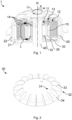
- FIG 1 is a sectional view of an external rotor motor 1 shown in perspective, with a cooling wheel 30 used in the external rotor motor 1 according to Figure 1 in figure 2 is shown.
- the rotor 20 can rotate about the stator 10 or about the axis of rotation R.
- the rotor 20 is fixedly connected to the housing 22 and via the housing to the bearing plate 21 and via the housing 22 and bearing plate 21 via bearings provided for this purpose to rotate or rotate about the axis of rotation R on the axis 40, with which the stator 10 is non-rotatably fixed connected is.
- the bearing plate 21 is connected to the housing 22 and sealed with respect to this, so that the housing formed by the housing 22 and the bearing plate 21 is essentially airtight and air flow into and out of the housing is prevented.
- the stator 10 has, radially on the inside, an inner section 11 through which air can flow and a radially outer outer section 12 through which air can flow, which is therefore further away from the axis of rotation R in the radial direction X than the inner section 11.
- the inner section 11 is fluidically separated from the outer section 12 by a ring element 15, so that at least on or in the stator 10 no air between inner portion 11 and outer portion 12 can flow.
- a cooling wheel 30 is rotatably fixed to the end shield 21 with the rotor 20, with the cooling wheel 30 due to the rotation about the axis 40 or about the axis of rotation R and due to its blades 33 creating a negative pressure on its inner diameter 31 and a positive pressure on its outer diameter 32 generated.
- the blades 33 of the cooling wheel 30 run with an upper edge, at least in sections, parallel and adjacent to the ring element 15, with an air gap being formed between the ring element 15 and the blades 33 or the upper edges of all blades 33, which allows free rotation of the cooling wheel 30 relative to the stator, but makes it difficult or impossible for air to flow back directly between the stator 10 and the cooling wheel 30 from the area with overpressure to the area with underpressure.
- the positive and negative pressure causes a directed air flow L from the outer diameter 32 of the cooling wheel 30 through the outer section 12 into a free space 13, which is opposite the end shield 21 with respect to the stator 10, and from the free space 13 generated by the inner section 11 to the inner diameter 31 of the cooling wheel 30 .
- the free space 13 fluidically connects the outer section 12 to the inner section 11 of the stator 10 and is delimited along the axis of rotation R by the stator 10 and the housing 22 .
- the directed air flow L or the air transported by the air flow L absorbs heat from stator windings 14 wound onto individual stator teeth of the stator 10 as it flows through the outer section 12 of the stator 10 and transfers the heat to cooler areas of the external rotor motor 1, for example on the housing 22, the inner section 11 or the axle 40, in order to cool the outer section 12 or the stator windings 14 in a defined manner by the directed air flow L.
Landscapes
- Engineering & Computer Science (AREA)
- Power Engineering (AREA)
- Motor Or Generator Cooling System (AREA)
Abstract
Description
- Die Erfindung betrifft einen Außenläufermotor mit einem Stator und einem Rotor sowie einem mit dem Rotor um eine Rotationsachse und den Stator rotierbaren Kühlrad zur Kühlung des Stators mittels eines gerichteten Luftstroms.
- Aus dem Stand der Technik ist eine Vielzahl von Elektromotoren bekannt, bei welchen Rotor und/oder Stator gekühlt werden. Dabei ist die Kühlung des Elektromotors bzw. dessen Komponenten für dessen Leistungsdichte ausschlaggebend, da mit einer Kühlung bzw. einer verbesserten Kühlung des Elektromotors eine entsprechend höhere Motorleistung erzeugt werden kann.
- Insbesondere bei Außenläufermotoren, bei welchen also der Rotor um einen innerhalb des Rotors angeordneten Stator rotiert, wird im Stand der Technik meist eine undefinierte Luftströmung genutzt, durch welche Luft verwirbelt und die Wärme vom Stator nur undefiniert bzw. vergleichsweise schlecht abgeführt werden kann.
- Der Erfindung liegt deshalb die Aufgabe zugrunde, die vorgenannten Nachteile zu überwinden und einen Außenläufermotor mit einer Kühlung bereitzustellen, durch welche eine definierte und hohe Kühlung des Motors realisierbar und eine entsprechend hohe Leistungsdichte des Elektromotors erreichbar ist.
- Diese Aufgabe wird durch die Merkmalskombination gemäß Patentanspruch 1 gelöst.
- Erfindungsgemäß wird daher ein Außenläufermotor mit einem Stator und einem Rotor sowie einem mit dem Rotor um eine Rotationsachse und den Stator rotierbaren Kühlrad zur Kühlung des Stators vorgeschlagen. Der Stator weist einen parallel zu der Rotationsachse durchströmbaren Innenabschnitt und einen parallel zu der Rotationsachse durchströmbaren Außenabschnitt auf, welcher den Innenabschnitt ringförmig umläuft und in Radialrichtung insbesondere im Bereich des Stators strömungstechnisch von dem Innenabschnitt getrennt ist, sodass also zumindest im Stator keine unmittelbare Luftströmung von dem Außenabschnitt zu dem Innenabschnitt möglich ist. Das Kühlrad weist eine Vielzahl von Schaufeln auf, welche benachbart und vorzugsweise unmittelbar benachbart zu dem Stator angeordnet und ausgebildet sind, an einem Außendurchmesser des Kühlrades benachbart zu dem Außenabschnitt des Stators einen Überdruck und an einem Innendurchmesser des Kühlrades benachbart zu dem Innenabschnitt des Stators einen Unterdruck zu erzeugen, sodass durch das Kühlrad eine gerichtete von dem Außendurchmesser des Kühlrades durch den Außenabschnitt und den Innenabschnitt zu dem Innendurchmesser des Kühlrades strömender Luftstrom erzeugbar ist.
- Da die Schaufeln benachbart und vorzugsweise unmittelbar benachbart zu dem Stator angeordnet sind, kann die Luft nicht unmittelbar von dem Überdruckbereich am Außendurchmesser des Kühlrades bzw. Außenabschnitt des Stators zu dem Unterdruckbereich am Innendurchmesser des Kühlrades bzw. Innenabschnitt des Stators strömen, sondern muss durch den Außenabschnitt und durch den Innenabschnitt des Stators strömen bzw. den Stator durchströmen.
- Dabei weist das Kühlrad bzw. die Schaufeln des Kühlrades zu dem Stator einen Luftspalt auf, welcher zwar eine Rotation des Kühlrades gegenüber dem Stator zulässt, bei einer Rotation des Kühlrades aber keine unmittelbare Luftströmung bzw. Rückströmung der Luft von dem Außendurchmesser bzw. Außenabschnitt zu dem Innendurchmesser bzw. Innenabschnitt erlaubt. Das kann erreicht werden, indem der Luftspalt entsprechend schmal ausgebildet bzw. die Schaufeln des Kühlrades entsprechend nah an dem Stator angeordnet werden.
- Zum Ausgleich des Luftdrucks zwischen dem Bereich mit dem Überdruck am Außendurchmesser des Kühlrades und dem Bereich mit dem Unterdruck am Innendurchmesser des Kühlrades wird daher eine gerichtete Luftströmung durch die durchströmbaren Abschnitte (Außenabschnitt, Innenabschnitt) des Stators erzeugt, welche auf einer von dem Kühlrad abgewandten Seite des Stators strömungstechnisch verbunden sind, sodass die durch den Stator strömende Luft insbesondere im Bereich des Außenabschnitts des Stators Wärme aufnimmt und an kühlere Bereiche des Stators bzw. des Außenläufers abgibt.
- Eine vorteilhafte Weiterbildung des Außenläufermotors sieht vor, dass das Kühlrad an einer dem Stator zugewandten Seite eines Lagerschilds fixiert ist, über welches der Rotor rotierbar an dem Stator gelagert ist.
- Hierfür kann das Kühlrad beispielsweise Rastelemente aufweisen, durch welche es mit von dem Lagerschild bereitgestellten Gegenrastabschnitten verrastbar und dadurch in Radialrichtung und Umlaufrichtung um die Rotationsachse an dem Lagerschild fixierbar ist.
- Weiter kann vorgesehen sein, dass der Außenläufermotor ferner ein den Stator umgebendes, mit dem Rotor rotierbares und einseitig von dem Lagerschild verschlossenes Gehäuse aufweist, welches beispielsweise glockenförmig bzw. als Rotorglocke ausgebildet sein kann. Eine durch das Gehäuse und das Lagerschild gebildete Einhausung ist strömungstechnisch dicht ausgebildet. Dabei ist unter strömungstechnisch dicht zu verstehen, dass die Einhausung den Stator luftdicht von einer die Einhausung umgebenden Umgebung trennt oder zumindest keine für die Kühlung des Stators relevante Luftströmung durch die Einhausung möglich ist.
- Um eine Übertragung der Wärme von dem Luftstrom auf kühlere Bereiche des Außenläufermotors zu unterstützen, kann vorgesehen sein, dass an dem Gehäuse und/oder dem Lagerschild Kühlrippen vorgesehen sind, durch welche eine mit dem Luftstrom beispielsweise von Statorwicklungen oder allgemein dem Außenabschnitt des Stators aufgenommene und entsprechend mit dem Luftstrom transportierte Wärme aus dem Luftstrom abführbar ist. Entsprechend kann die Wärme von den Statorwicklungen an die mit der Luftströmung transportierte Luft und von der Luft insbesondere über die Kühlrippen an das Gehäuse und/oder das Lagerschild bzw. die Einhausung abgegeben werden, sodass das Gehäuse die Wärme nach außen bzw. in die die Einhausung umgebende Umgebung abtransportiert und die Statorwicklungen mithin gekühlt werden können.
- Um an der von dem Kühlrad abgewandten Seite des Stators eine Luftströmung zwischen dem Außen- und dem Innenabschnitt des Stators zu ermöglichen, ist gemäß einer vorteilhaften Weiterbildung an einer entlang der Rotationsachse von dem Kühlrad abgewandten Seite des Stators ein den Außenabschnitt strömungstechnisch mit den Innenabschnitt verbindender Freiraum vorgesehen. Der Freiraum kann dabei beispielsweise von dem Stator und dem Gehäuse begrenzt werden. Alternativ kann der Freiraum bzw. ein den Außenabschnitt mit dem Innenabschnitt verbindender Abschnitt auch innerhalb des Stators und vorzugsweise an einem von dem Kühlrad abgewandten Ende des Stators ausgebildet sein.
- Ferner kann der Stator eine Vielzahl von Statorzähnen aufweisen, welche jeweils einen Wicklungsabschnitt zur Aufnahme von Statorwicklungen in dem Außenabschnitt des Stators und einen Anbindungsabschnitt zur Anbindung des Stators an eine Achse des Elektromotors in dem Innenabschnitt des Stators aufweisen. Dabei sind vorzugsweise Zwischenräume zwischen den Wicklungen bzw. Zwischenräume zwischen den Wickelabschnitten der Statorzähne durchströmbar. Im Bereich der Anbindungsabschnitte sind vorzugsweise Zwischenräume zwischen den Anbindungsabschnitten der Statorzähne durchströmbar oder hierfür Kühlkanäle vorgesehen.
- Gemäß einer vorteilhaften Weiterbildung kann der Stator aus einer Vielzahl von Einzelzähnen gebildet sein, welche an einem Verbindungsabschnitt in Umfangsrichtung miteinander mechanisch verbunden sind.
- Weiter kann der Stator ein den Innenabschnitt von dem Außenabschnitt strömungstechnisch trennendes Ringelement aufweisen.
- Ist der Stator aus einer Vielzahl von Einzelzähnen gebildet, kann das Ringelement durch die Verbindungsabschnitte der Einzelzähne gebildet werden, sodass also die miteinander in Verbindung stehenden Verbindungsabschnitte der Vielzahl von Einzelzähnen das Ringelement bilden.
- Ist ein den Innenabschnitt von dem Außenabschnitt strömungstechnisch trennendes Ringelement vorgesehen, erstreckt sich dieses vorzugsweise parallel zu der Rotationsachse entlang des gesamten Stators.
- Das in Umfangsrichtung um die Rotationsachse vorzugsweise vollständig geschlossene und sich parallel zu der Rotationsachse über die gesamte Länge des Stators erstreckende Ringelement kann entsprechend die strömungstechnische Trennung des Außenabschnitts und des Innenabschnitts des Stators derart ermöglichen, dass der Luftstrom zunächst den Außenbereich und anschließend den Innenbereich des Stators durchströmen muss, um einen Druckausgleich zwischen dem Überdruck und dem Unterdruck zu ermöglichen.
- Weiter vorzugsweise verlaufen die Schaufeln des Kühlrades unmittelbar benachbart sowie zumindest abschnittsweise parallel zu dem Ringelement, sodass zwischen dem Ringelement und den Schaufeln bzw. einer durch die dem Ringelement zugewandte Grenzfläche aller Schaufeln des Kühlrades ein schmaler Luftspalt bestimmt ist. Dabei ist der Luftspalt derart ausgebildet, dass eine freie Rotation des Kühlrades gegenüber dem Stator ermöglicht, ein Rückströmen bzw. ein Strömen der Luft von dem Außenabschnitt zu dem Innenabschnitt nicht möglich ist.
- Vorteilhaft ist auch eine Variante, bei welcher das Kühlrad einen geschlossenen Ring aufweist, auf welchem die Schaufeln in Radialrichtung verlaufen und von welchem die Schaufeln parallel zu der Rotationsachse in Richtung des Stators abstehen.
- Der Ring kann dabei zugleich der Montage an dem Lagerschild dienen. Beispielsweise kann er flächig auf dem Lagerschild aufliegen und/oder Rastelemente zur Verrastung mit Gegenrastelementen des Lagerschildes aufweisen.
- Die vorstehend offenbarten Merkmale sind beliebig kombinierbar, soweit dies technisch möglich ist und diese nicht im Widerspruch zueinander stehen.
- Andere vorteilhafte Weiterbildungen der Erfindung sind in den Unteransprüchen gekennzeichnet bzw. werden nachstehend zusammen mit der Beschreibung der bevorzugten Ausführung der Erfindung anhand der Figuren näher dargestellt. Es zeigen:
- Fig. 1
- Schnitt durch einen Außenläufer;
- Fig. 2
- Kühlrad eines Außenläufers.
- Die Figuren sind beispielhaft schematisch. Gleiche Bezugszeichen in den Figuren weisen auf gleiche funktionale und/oder strukturelle Merkmale hin.
- In
Figur 1 ist eine Schnittansicht eines perspektivisch dargestellten Außenläufermotors 1 dargestellt, wobei ein in dem Außenläufermotor 1 gemäß Figur 1 verwendetes Kühlrad 30 inFigur 2 abgebildet ist. Dabei kann der Rotor 20 um den Stator 10 bzw. um die Rotationsachse R rotieren. Der Rotor 20 ist fest mit dem Gehäuse 22 und über das Gehäuse mit dem Lagerschild 21 verbunden sowie über Gehäuse 22 und Lagerschild 21 über dafür vorgesehene Lager um die Rotationsachse R rotier- bzw. drehbar an der Achse 40 fixiert, mit welcher der Stator 10 drehfest verbunden ist. - Vorliegend ist das Lagerschild 21 mit dem Gehäuse 22 verbunden und gegenüber diesem abgedichtet, sodass die durch das Gehäuse 22 und das Lagerschild 21 gebildete Einhausung im Wesentlichen luftdicht ist und eine Luftströmung in und aus der Einhausung verhindert wird.
- Der Stator 10 weist radialinnen einen von Luft durchströmbaren Innenabschnitt 11 und einen radialäußeren von Luft druchströmbaren Außenabschnitt 12 auf, welcher also in Radialrichtung X weiter von der Rotationsachse R entfernt ist, als der Innenabschnitt 11.
- Der Innenabschnitt 11 ist strömungstechnisch durch ein Ringelement 15 von dem Außenabschnitt 12 getrennt, sodass also zumindest am bzw. im Stator 10 keine Luft zwischen Innenabschnitt 11 und Außenabschnitt 12 strömen kann.
- Ein Kühlrad 30 ist mit dem Rotor 20 rotierbar an dem Lagerschild 21 fixiert, wobei das Kühlrad 30 durch die Rotation um die Achse 40 bzw. um die Rotationsachse R sowie durch seine Schaufeln 33 an seinem Innendurchmesser 31 einen Unterdruck und an seinem Außendurchmesser 32 einen Überdruck erzeugt.
- Die Schaufeln 33 des Kühlrades 30 verlaufen dabei mit einer Oberkante zumindest abschnittsweise parallel und benachbart zu dem Ringelement 15, wobei ein zwischen dem Ringelement 15 und den Schaufeln 33 bzw. den Oberkanten aller Schaufeln 33 ein Luftspalt gebildet wird, der zwar eine freie Rotation des Kühlrades 30 gegenüber dem Stator ermöglicht, ein unmittelbares Rückströmen von Luft zwischen dem Stator 10 und dem Kühlrad 30 von dem Bereich mit Überdruck zu dem Bereich mit Unterdruck jedoch erschwert bzw. verhindert.
- Zum Ausgleich des Druckes in der Einhausung wird durch den Überdruck und den Unterdruck daher eine gerichtete Luftströmung L von dem Außendurchmesser 32 des Kühlrades 30 durch den Außenabschnitt 12 in einen Freiraum 13, welcher dem Lagerschild 21 bezüglich des Stators 10 gegenüberliegt, und von dem Freiraum 13 durch den Innenabschnitt 11 zu dem Innendurchmesser 31 des Kühlrades 30 erzeugt. Der Freiraum 13 verbindet dabei den Außenabschnitt 12 strömungstechnisch mit dem Innenabschnitt 11 des Stators 10 und wird entlang der Rotationsachse R von dem Stator 10 und dem Gehäuse 22 begrenzt.
- Die gerichtete Luftströmung L bzw. die von der Luftströmung L transportierte Luft nimmt beim Durchströmen des Außenabschnitts 12 des Stators 10 von auf einzelne Statorzähne des Stators 10 gewickelte Statorwicklungen 14 Wärme auf und gibt die Wärme an kühlere Bereiche des Außenläufermotors 1, also beispielsweise an das Gehäuse 22, den Innenabschnitt 11 oder die Achse 40 ab, um so den Außenabschnitt 12 bzw. die Statorwicklungen 14 in definierter Weise durch die gerichtete Luftströmung L zu kühlen.
- Die Erfindung beschränkt sich in ihrer Ausführung nicht auf die vorstehend angegebenen bevorzugten Ausführungsbeispiele. Vielmehr ist eine Anzahl von Varianten denkbar, welche von der dargestellten Lösung auch bei grundsätzlich anders gearteten Ausführungen Gebrauch macht.
Claims (10)
- Außenläufermotor (1) mit einem Stator (10) und einem Rotor (20) sowie einem mit dem Rotor (20) um eine Rotationsachse (R) und den Stator (10) rotierbaren Kühlrad (30) zur Kühlung des Stators (10),wobei der Stator (10) einen parallel zu der Rotationsachse (R) durchströmbaren Innenabschnitt (11) und einen parallel zu der Rotationsachse (R) durchströmbaren Außenabschnitt (12) aufweist, welcher den Innenabschnitt (11) ringförmig umläuft und in Radialrichtung (X) strömungstechnisch von dem Innenabschnitt (11) getrennt ist,wobei das Kühlrad (30) eine Vielzahl von Schaufeln (33) aufweist, welche benachbart zu dem Stator (10) angeordnet und ausgebildet sind, an einem Außendurchmesser (32) des Kühlrades (30) benachbart zu dem Außenabschnitt (12) einen Überdruck und an einem Innendurchmesser (31) des Kühlrades (30) benachbart zu dem Innenabschnitt (11) einen Unterdruck zu erzeugen, sodass durch das Kühlrad (30) eine gerichtete von dem Außendurchmesser (32) des Kühlrades (30) durch den Außenabschnitt (12) und den Innenabschnitt (11) zu dem Innendurchmesser (31) des Kühlrades (30) strömender Luftstrom (L) erzeugbar ist.
- Außenläufermotor nach Anspruch 1,
wobei das Kühlrad (30) an einer dem Stator (10) zugewandten Seite eines Lagerschilds (21) fixiert ist, über welches der Rotor (20) rotierbar an dem Stator (10) gelagert ist. - Außenläufermotor nach Anspruch 2,ferner aufweisend ein den Stator (10) umgebendes, mit dem Rotor (20) rotierbares und einseitig von dem Lagerschild (21) verschlossenes Gehäuse (22),wobei eine durch das Gehäuse (22) und das Lagerschild (21) gebildete Einhausung strömungstechnisch dicht ausgebildet ist.
- Außenläufermotor nach Anspruch 1 oder 2,
wobei an dem Gehäuse (22) und/oder dem Lagerschild (21) Kühlrippen vorgesehen sind, durch welche eine mit dem Luftstrom (L) transportierte Wärme aus dem Luftstrom (L) abführbar ist. - Außenläufermotor nach einem der vorhergehenden Ansprüche,
wobei an einer entlang der Rotationsachse (R) von dem Kühlrad (30) abgewandten Seite des Stators (10) ein den Außenabschnitt (12) strömungstechnisch mit den Innenabschnitt (11) verbindender Freiraum (13) vorgesehen ist. - Außenläufermotor nach einem der vorhergehenden Ansprüche,
wobei der Stator (10) eine Vielzahl von Statorzähnen aufweist, welche jeweils einen Wicklungsabschnitt zur Aufnahme von Statorwicklungen (14) in dem Außenabschnitt des Stators und einen Anbindungsabschnitt zur Anbindung des Stators (10) an eine Achse (40) des Elektromotors (1) in dem Innenabschnitt des Stators (10) aufweisen. - Außenläufermotor nach dem vorhergehenden Anspruch,
wobei der Stator (10) aus einer Vielzahl von Einzelzähnen gebildet ist, welche an einem Verbindungsabschnitt in Umfangsrichtung (U) miteinander mechanisch verbunden sind. - Außenläufermotor nach einem der vorhergehenden Ansprüche,
wobei der Stator (10) ein den Innenabschnitt (11) von dem Außenabschnitt (12) strömungstechnisch trennendes Ringelement (15) aufweist. - Außenläufermotor nach dem vorhergehenden Anspruch,
wobei das Ringelement (15) sich parallel zu der Rotationsachse (R) entlang des gesamten Stators (10) erstreckt. - Außenläufermotor nach einem der vorhergehenden Ansprüche,
wobei das Kühlrad (30) einen geschlossenen Ring (34) aufweist, auf welchem die Schaufeln (33) in Radialrichtung (X) verlaufen und von welchem die Schaufeln (33) parallel zu der Rotationsachse (R) in Richtung des Stators (10) abstehen.
Applications Claiming Priority (1)
| Application Number | Priority Date | Filing Date | Title |
|---|---|---|---|
| DE102021120673.1A DE102021120673A1 (de) | 2021-08-09 | 2021-08-09 | Außenläufermotor mit einem Kühlrad zur Kühlung des Stators |
Publications (1)
| Publication Number | Publication Date |
|---|---|
| EP4135169A1 true EP4135169A1 (de) | 2023-02-15 |
Family
ID=82748692
Family Applications (1)
| Application Number | Title | Priority Date | Filing Date |
|---|---|---|---|
| EP22187218.7A Pending EP4135169A1 (de) | 2021-08-09 | 2022-07-27 | Aussenläufermotor mit einem kühlrad zur kühlung des stators |
Country Status (4)
| Country | Link |
|---|---|
| US (1) | US12573916B2 (de) |
| EP (1) | EP4135169A1 (de) |
| CN (1) | CN115912787A (de) |
| DE (1) | DE102021120673A1 (de) |
Cited By (1)
| Publication number | Priority date | Publication date | Assignee | Title |
|---|---|---|---|---|
| RU2850891C1 (ru) * | 2025-05-20 | 2025-11-17 | федеральное государственное бюджетное образовательное учреждение высшего образования "Уфимский университет науки и технологий" | Электрический двигатель с интенсивным охлаждением |
Families Citing this family (1)
| Publication number | Priority date | Publication date | Assignee | Title |
|---|---|---|---|---|
| KR102654663B1 (ko) * | 2021-09-29 | 2024-04-05 | 엘지전자 주식회사 | 외전형 모터 |
Citations (3)
| Publication number | Priority date | Publication date | Assignee | Title |
|---|---|---|---|---|
| US5698913A (en) * | 1995-06-15 | 1997-12-16 | Kabushiki Kaisha Toshiba | Outer-rotor type electric rotary machine and electric motor vehicle using the machine |
| CN205141922U (zh) * | 2015-11-13 | 2016-04-06 | 苏州工业园区泰格电子科技有限公司 | 一种外转子电机 |
| WO2017148415A1 (zh) * | 2016-03-02 | 2017-09-08 | 罗伯特·博世有限公司 | 外转子式电机 |
Family Cites Families (8)
| Publication number | Priority date | Publication date | Assignee | Title |
|---|---|---|---|---|
| JP3987027B2 (ja) * | 2003-03-31 | 2007-10-03 | 三菱電機株式会社 | 回転電機の電機子 |
| KR100587298B1 (ko) * | 2003-12-10 | 2006-06-08 | 엘지전자 주식회사 | 드럼세탁기용 아웃터로터형 모터의 스테이터 코어 및백요크 제조방법 |
| DE102006041122B4 (de) | 2005-10-08 | 2020-11-05 | Papst Licensing Gmbh & Co. Kg | Außenläufermotor |
| DE102011053611A1 (de) * | 2011-09-14 | 2013-03-14 | Ebm-Papst Mulfingen Gmbh & Co. Kg | Rotierende elektrische Maschine |
| DE102012107107B4 (de) * | 2012-08-02 | 2021-11-11 | Ebm-Papst Mulfingen Gmbh & Co. Kg | Aktive Kühlung eines Motors |
| GB2538526B (en) * | 2015-05-19 | 2021-05-26 | Yasa Ltd | Axial flux machine |
| JP7028175B2 (ja) * | 2016-09-02 | 2022-03-02 | 日本電産株式会社 | ステータ、ステータの製造方法及びモータ |
| DE102019214518A1 (de) * | 2019-09-24 | 2021-03-25 | Rolls-Royce Deutschland Ltd & Co Kg | Statorzahnanordnung |
-
2021
- 2021-08-09 DE DE102021120673.1A patent/DE102021120673A1/de not_active Withdrawn
-
2022
- 2022-07-27 EP EP22187218.7A patent/EP4135169A1/de active Pending
- 2022-08-03 CN CN202210925531.6A patent/CN115912787A/zh active Pending
- 2022-08-05 US US17/881,735 patent/US12573916B2/en active Active
Patent Citations (3)
| Publication number | Priority date | Publication date | Assignee | Title |
|---|---|---|---|---|
| US5698913A (en) * | 1995-06-15 | 1997-12-16 | Kabushiki Kaisha Toshiba | Outer-rotor type electric rotary machine and electric motor vehicle using the machine |
| CN205141922U (zh) * | 2015-11-13 | 2016-04-06 | 苏州工业园区泰格电子科技有限公司 | 一种外转子电机 |
| WO2017148415A1 (zh) * | 2016-03-02 | 2017-09-08 | 罗伯特·博世有限公司 | 外转子式电机 |
Cited By (3)
| Publication number | Priority date | Publication date | Assignee | Title |
|---|---|---|---|---|
| RU2850890C1 (ru) * | 2025-05-14 | 2025-11-17 | федеральное государственное бюджетное образовательное учреждение высшего образования "Уфимский университет науки и технологий" | Электрический двигатель с внешним ротором |
| RU2850891C1 (ru) * | 2025-05-20 | 2025-11-17 | федеральное государственное бюджетное образовательное учреждение высшего образования "Уфимский университет науки и технологий" | Электрический двигатель с интенсивным охлаждением |
| RU2850892C1 (ru) * | 2025-05-20 | 2025-11-17 | федеральное государственное бюджетное образовательное учреждение высшего образования "Уфимский университет науки и технологий" | Электрический двигатель с встроенным устройством охлаждения |
Also Published As
| Publication number | Publication date |
|---|---|
| CN115912787A (zh) | 2023-04-04 |
| US12573916B2 (en) | 2026-03-10 |
| DE102021120673A1 (de) | 2023-02-09 |
| US20230043728A1 (en) | 2023-02-09 |
Similar Documents
| Publication | Publication Date | Title |
|---|---|---|
| DE839225C (de) | Fuer verschiedene Schutzarten umbaubare dynamoelektrische Maschine | |
| WO2020099048A1 (de) | Stützeinrichtung für einen rotor einer fremderregten innenläufer-synchronmaschine bestehend aus einem stützring und einer sternscheibe | |
| DE102018117463A1 (de) | Stator für einen Elektromotor, Elektromotor mit dem Stator sowie elektrischer Antrieb mit dem Elektromotor | |
| DE102010044453A1 (de) | Bürstenloser Motor | |
| DE102009036466A1 (de) | Elektromotor | |
| EP1649575A1 (de) | Elektrische maschine mit läuferkühlung und entsprechendes kühlungsverfahren | |
| EP3127223B1 (de) | Elektrische maschine | |
| CH716015A2 (de) | Kühlung von Rotor- und Statorkomponenten eines Turboladers mit Hilfe von additiv gefertigten bauteilinternen Kühlkanälen. | |
| DE102016210930A1 (de) | Rotorblechpaket für eine elektrische Maschine | |
| DE102015015797A1 (de) | Elektrische Maschine, insbesondere für einen Kraftwagen | |
| DE102014202055A1 (de) | Elektrische Maschine | |
| EP3584910B1 (de) | Elektrische maschine mit verbesserter abfuhr von verlustwärme | |
| DE102016223964A1 (de) | Kraftfahrzeuggetriebeeinrichtung mit einer elektrischen Maschine und einer einteiligen Rotor-Getriebeeingangswelle | |
| EP3888230B1 (de) | Rotor einer elektrischen maschine | |
| EP3308449B1 (de) | Statorring für einen elektrischen generator, sowie generator und windenergieanlage mit selbigem | |
| EP4135169A1 (de) | Aussenläufermotor mit einem kühlrad zur kühlung des stators | |
| CH677009A5 (de) | ||
| DE102018130516A1 (de) | Rotorwelle | |
| EP3796523A1 (de) | Statorring für einen elektrischen generator und elektrischer generator mit einem solchen statorring | |
| DE102008017376A1 (de) | Generatorgehäuse für eine Windenergieanlage | |
| DE102016004936B4 (de) | Elektrische Maschine | |
| EP3762613B1 (de) | Vakuumpumpe | |
| DE102019215454A1 (de) | Elektrische Maschine | |
| DE102017201390A1 (de) | Rotor für eine elektrische Maschine, elektrische Maschine, insbesondere Asynchronmaschine, für ein Kraftfahrzeug und Kraftfahrzeug | |
| DE102014206109A1 (de) | Drehteile eines Planetengetriebes |
Legal Events
| Date | Code | Title | Description |
|---|---|---|---|
| PUAI | Public reference made under article 153(3) epc to a published international application that has entered the european phase |
Free format text: ORIGINAL CODE: 0009012 |
|
| STAA | Information on the status of an ep patent application or granted ep patent |
Free format text: STATUS: THE APPLICATION HAS BEEN PUBLISHED |
|
| AK | Designated contracting states |
Kind code of ref document: A1 Designated state(s): AL AT BE BG CH CY CZ DE DK EE ES FI FR GB GR HR HU IE IS IT LI LT LU LV MC MK MT NL NO PL PT RO RS SE SI SK SM TR |
|
| STAA | Information on the status of an ep patent application or granted ep patent |
Free format text: STATUS: REQUEST FOR EXAMINATION WAS MADE |
|
| 17P | Request for examination filed |
Effective date: 20230809 |
|
| RBV | Designated contracting states (corrected) |
Designated state(s): AL AT BE BG CH CY CZ DE DK EE ES FI FR GB GR HR HU IE IS IT LI LT LU LV MC MK MT NL NO PL PT RO RS SE SI SK SM TR |
|
| STAA | Information on the status of an ep patent application or granted ep patent |
Free format text: STATUS: EXAMINATION IS IN PROGRESS |
|
| 17Q | First examination report despatched |
Effective date: 20250918 |