EP4134990A1 - Bobine magnétique pourvue de structure de refroidissement et électrovanne dotée d'une telle bobine magnétique - Google Patents
Bobine magnétique pourvue de structure de refroidissement et électrovanne dotée d'une telle bobine magnétique Download PDFInfo
- Publication number
- EP4134990A1 EP4134990A1 EP22188782.1A EP22188782A EP4134990A1 EP 4134990 A1 EP4134990 A1 EP 4134990A1 EP 22188782 A EP22188782 A EP 22188782A EP 4134990 A1 EP4134990 A1 EP 4134990A1
- Authority
- EP
- European Patent Office
- Prior art keywords
- magnetic coil
- heat sink
- coil
- energy
- magnetic
- Prior art date
- Legal status (The legal status is an assumption and is not a legal conclusion. Google has not performed a legal analysis and makes no representation as to the accuracy of the status listed.)
- Pending
Links
Images


Classifications
-
- H—ELECTRICITY
- H01—ELECTRIC ELEMENTS
- H01F—MAGNETS; INDUCTANCES; TRANSFORMERS; SELECTION OF MATERIALS FOR THEIR MAGNETIC PROPERTIES
- H01F5/00—Coils
-
- F—MECHANICAL ENGINEERING; LIGHTING; HEATING; WEAPONS; BLASTING
- F16—ENGINEERING ELEMENTS AND UNITS; GENERAL MEASURES FOR PRODUCING AND MAINTAINING EFFECTIVE FUNCTIONING OF MACHINES OR INSTALLATIONS; THERMAL INSULATION IN GENERAL
- F16K—VALVES; TAPS; COCKS; ACTUATING-FLOATS; DEVICES FOR VENTING OR AERATING
- F16K31/00—Actuating devices; Operating means; Releasing devices
- F16K31/02—Actuating devices; Operating means; Releasing devices electric; magnetic
- F16K31/06—Actuating devices; Operating means; Releasing devices electric; magnetic using a magnet, e.g. diaphragm valves, cutting off by means of a liquid
- F16K31/0675—Electromagnet aspects, e.g. electric supply therefor
-
- F—MECHANICAL ENGINEERING; LIGHTING; HEATING; WEAPONS; BLASTING
- F16—ENGINEERING ELEMENTS AND UNITS; GENERAL MEASURES FOR PRODUCING AND MAINTAINING EFFECTIVE FUNCTIONING OF MACHINES OR INSTALLATIONS; THERMAL INSULATION IN GENERAL
- F16K—VALVES; TAPS; COCKS; ACTUATING-FLOATS; DEVICES FOR VENTING OR AERATING
- F16K49/00—Means in or on valves for heating or cooling
-
- H—ELECTRICITY
- H01—ELECTRIC ELEMENTS
- H01F—MAGNETS; INDUCTANCES; TRANSFORMERS; SELECTION OF MATERIALS FOR THEIR MAGNETIC PROPERTIES
- H01F7/00—Magnets
- H01F7/06—Electromagnets; Actuators including electromagnets
-
- H—ELECTRICITY
- H01—ELECTRIC ELEMENTS
- H01F—MAGNETS; INDUCTANCES; TRANSFORMERS; SELECTION OF MATERIALS FOR THEIR MAGNETIC PROPERTIES
- H01F27/00—Details of transformers or inductances, in general
- H01F27/02—Casings
- H01F27/025—Constructional details relating to cooling
-
- H—ELECTRICITY
- H01—ELECTRIC ELEMENTS
- H01F—MAGNETS; INDUCTANCES; TRANSFORMERS; SELECTION OF MATERIALS FOR THEIR MAGNETIC PROPERTIES
- H01F27/00—Details of transformers or inductances, in general
- H01F27/28—Coils; Windings; Conductive connections
- H01F27/2876—Cooling
Definitions
- the invention relates to a magnetic coil according to the preamble of patent claim 1 and a magnetic valve with such a magnetic coil.
- Magnetic coils can be used to convert electrical energy into magnetic energy.
- magnetic coils have a conducting wire inside them, which is arranged in a large number of windings lying on top of one another.
- a magnetic field is generated in the lead wire by the electrical energy supplied to the magnetic coil, as a result of which the magnetic coil is excited.
- the coiled wire encloses an iron core which amplifies the magnetic field generated in the wire. With the help of the magnetic field thus generated, components formed separately can be attracted and thus moved by the magnetic coil.
- a solenoid valve can be switched / actuated with the help of a solenoid coil.
- an electrical connection of a magnetic coil is connected to an energy source.
- the energy source usually in the form of a 24V voltage
- the magnetic coil generates a magnetic field and thus converts the electrical energy into magnetic energy.
- a piston arranged in the magnet valve is moved (attracted) by the magnetic field generated by the magnet coil in such a way that a media inlet and a media outlet of the magnet valve are connected to one another. In this way, the solenoid valve is opened and a medium can flow through.
- the solenoid When power is removed from the solenoid, the solenoid ceases to generate a magnetic field, so the plunger is no longer attracted to the solenoid and returns to its home position.
- the media inlet and the media outlet of the solenoid valve are separated from each other again. In this case, the solenoid valve is in the closed state and no medium can flow through the solenoid valve.
- Solenoid valves of this type which are switched by a magnetic coil, can be used, for example, as actuators for driving a valve body of an injection nozzle, as shown, inter alia, in US Pat DE 10 2007 000 358 A1 described.
- a pulse width modulation amplifier can be connected to the solenoid valve.
- the switching time of the solenoid valve is significantly reduced by the amplifier.
- the magnetic coil has to be energized for less time.
- such a method for extending the life of the magnet coil is complex and expensive.
- the invention is based on the object of providing a magnetic coil whose service life can be (further) extended.
- the service life of the magnetic coil should be extended in a simple and cost-effective manner.
- the claimed solenoid coil is designed to actuate/switch/change a valve position of a solenoid valve.
- the magnetic coil has an essentially cylindrical coil outer surface.
- the outer surface of the magnetic coil has a cooling structure which increases the outer surface.
- the energized magnetic coil heats up due to the supply of electrical energy and the heating of the magnetic coil has a negative impact on its service life. Because the outer surface of the coil has a cooling structure, the heat generated by the magnetic coil can be dissipated to the environment in a simple and uncomplicated manner. Thus, the heating effect of the magnet coil with a cooling structure on its outer surface is significantly reduced compared to a magnet coil without a cooling structure. Thus, the life of the magnet coil having a cooling structure on its outer surface can be remarkably extended compared to that of conventional magnet coils.
- the cooling structure is provided as a passive heat sink with cooling fins that is formed separately from the outer surface of the magnetic coil.
- a passive heatsink with cooling fins is easy and inexpensive to manufacture.
- the passive heat sink increases its surface area and dissipates the heat generated by the magnet coil to the environment via its cooling fins.
- the heat sink is provided separately from the magnet coil, it can be arranged on the magnet coil or removed from it as required, for example if the area around the magnet coil does not offer enough space for the heat sink.
- the heatsink can also be easily replaced.
- the passive heat sink has a hollow cylindrical shape and is arranged on the outer surface of the heat sink Cooling fins extend in the circumferential direction of the heatsink, in particular parallel to one another, and are spaced apart in the longitudinal direction of the heatsink, in particular always at the same distance, and are interrupted by at least one longitudinal slot, in particular by two diametrically opposite longitudinal slots.
- a first longitudinal slot is continuously provided in the radial direction, so that the heat sink wall surface is continuously interrupted at this point in the longitudinal direction.
- a second longitudinal slot diametrically opposite the first longitudinal slot is not provided continuously in the radial direction, but is provided as a longitudinal direction of the heat sink, in particular over the entire length of the heat sink, extending notch on the outer wall of the heat sink and serves as a predetermined bending point.
- cooling fins are distributed over the entire height/length of the hollow-cylindrical heat sink.
- Such an arrangement of the cooling ribs on the passive heat sink allows the surface area for dissipating the heat generated by the magnetic coil to be optimally enlarged.
- the height/length of the hollow-cylindrical heat sink corresponds (roughly) to the height/length of the cylindrical magnet coil.
- the entire outer surface of the magnet coil can thus be covered with cooling fins, so that the heat conduction via these cooling fins is optimal.
- the inner dimension of the hollow-cylindrical passive heat sink is smaller than the outer dimension of the magnetic coil (undersized) so that the passive heat sink can be press-fitted onto the outer surface of the coil when it is arranged and the at least one (the first) longitudinal slit widened.
- the inner dimension, in particular the inner diameter of the hollow-cylindrical heat sink is at least slightly smaller than the outer dimension, in particular the outer diameter, of the cylindrical magnetic coil. Furthermore, it is possible through the at least one longitudinal slot (as well as alternatively or additionally due to the material elasticity of the hollow-cylindrical heat sink) to reversibly expand the heat sink for arranging it on the magnetic coil. If the heat sink is arranged on the magnetic coil, the restoring force inherent in the heat sink material acts in such a way that the heat sink "encloses" the magnetic coil and is thus firmly arranged on it. Due to these features, the heat sink can be easily and securely arranged on the magnetic coil.
- the passive heat sink has a (semi-)circular shape and the cooling ribs arranged on the outer surface of the heat sink extend in the longitudinal direction of the heat sink and are spaced apart from one another in the circumferential direction of the heat sink, in particular always at the same distance.
- the cooling fins are advantageously distributed over at least part of the circumference of the heat sink.
- the cooling fins extend over the entire height / length of the arc-shaped heat sink, but are only distributed over part of the heat sink's circumference. If this passive heat sink is arranged on the magnetic coil, the cooling ribs can dissipate the heat from the magnetic coil to its surroundings particularly well due to their arrangement.
- the height/length of the circular heat sink is less than the height/length of the cylindrical magnetic coil.
- the passive heat sink only covers part of the outer surface of the coil.
- Such heat sinks in the form of a circular arc can be sufficient for cooling the magnetic coil in certain applications and are cheaper and take up less space than, for example, the passive hollow-cylindrical heat sink that covers the entire outer surface of the coil.
- the passive heat sink in the form of a circular arc if it has no cooling ribs in its end regions in the circumferential direction. In this case, these end portions can be gripped more easily and easily arranged on the magnet coil.
- the inner dimension of the (semi-) circular arc-shaped passive heat sink is smaller than an outer dimension of the magnetic coil (to an undersize) so that the passive heat sink can be press-fitted onto the outer surface of the coil when it is arranged on it.
- the inner dimension, in particular the inner radius of the (semi-)circular heat sink is at least slightly smaller than the outer dimension, in particular the outer radius, of the cylindrical magnetic coil. Due to the material elasticity of the (semi-)circular heat sink, the heat sink can be reversibly expanded for arranging it on the magnetic coil. If the heat sink is arranged on the magnetic coil, the restoring force inherent in the heat sink material acts in such a way that the heat sink "encloses" the magnetic coil and is thus firmly arranged on it. Due to these features, the heat sink can be easily and securely arranged on the magnetic coil.
- the hollow-cylindrical cooling body covering the entire outer surface of the coil and the cooling body in the form of a circular arc covering only part of the outer surface of the coil are made of metal.
- cooling structure is designed as a heat sink that is actively ventilated (actively cooling) and supplied with external energy separately from the outer surface of the magnetic coil.
- the heat sink which is arranged on the magnet coil, is an actively ventilated one (hereinafter also simply referred to as an active heat sink), it can dissipate more heat from the magnet coil to the environment compared to a passive heat sink.
- the arrangement of an active heat sink on the magnet coil is particularly useful if there is a risk of the magnet coil heating up significantly.
- the actively ventilated, externally powered heat sink has a fan that is supplied with power from a power source that is at least embodied separately from the magnetic coil.
- the active heat sink can cool the magnetic coil particularly effectively.
- the cooling structure is designed as an energy self-supply cooling body that is actively ventilated separately from the outer surface of the magnet coil.
- Energy self-sufficient here means that the active heat sink arranged on the magnetic coil receives its energy from the magnetic coil.
- the actively ventilated, energy self-supplying heat sink has a fan which is supplied with energy loss, in particular in the form of (waste) heat, from the magnetic coil.
- energy loss in particular in the form of (waste) heat
- the thermal energy from the magnetic coil can be used to drive the fan of the active heat sink.
- Such a self-sufficient active heat sink is therefore extremely energy-efficient and no energy supply from an external energy source is required.
- the actively ventilated, self-supplying heat sink (in particular its fan) is preferably supplied with a feeding signal from the magnetic coil.
- the solenoid valve or the solenoid coil and the actively ventilated, self-sufficient heat sink (or its fan) are switched on at the same time via a control signal, which puts the solenoid valve into an active / switching state.
- thermocouple or a thermoelectric generator is arranged between the magnetic coil and the heat sink, in particular between the magnetic coil and the fan, which converts the energy loss from the magnetic coil into a form of energy, in particular into an electrical voltage, which Fan of the heat sink is supplied.
- thermocouple With the help of the thermocouple or the thermoelectric generator, electrical energy (voltage) can be generated from the waste heat of the magnetic coil, which is then fed to the active, self-sufficient heat sink to drive its fan.
- the actively ventilated (externally powered or self-powered) heat sink in particular its fan, is only active (the fan rotates) when the solenoid valve or the solenoid coil is active.
- the actively ventilated (externally energy-supplied or the energy self-supplying) heat sink also cools when the magnetic valve or the magnetic coil is inactive. So there are possibilities that the actively ventilated heatsink only cools when the solenoid valve is active, and that the actively ventilated heatsink cools regardless of the solenoid valve's active state (continuously).
- a further embodiment provides that the outer surface of the magnetic coil itself is designed at least partially, in particular completely, as a cooling structure in the form of cooling ribs.
- the magnetic coil is designed as a hollow cylinder which has integrally on its outer surface, in particular on the entire outer surface, a large number of cooling ribs running in the longitudinal direction of the hollow cylinder, in particular parallel to one another and projecting outwards from the outer surface.
- the cooling fins are spaced apart from one another in the circumferential direction, in particular always at the same distance from one another.
- cooling fins which are part of (integral with) the outer surface of the magnet coil, run in the circumferential direction of the essentially cylindrical magnet coil and are spaced apart from one another in its longitudinal direction.
- the magnetic valve according to the invention has a magnetic coil as described above. Furthermore, the solenoid valve has at least one valve body, a valve seat and a closing element. The solenoid brings the closure member into contact with the valve seat and terminates contact between the closure member and the valve seat to actuate the solenoid valve between at least closed and open positions.
- the magnetic coil has a cooling structure on its outer surface that enlarges it, at least the majority of the (waste) heat generated by the magnetic coil is dissipated to the environment and the magnetic coil hardly heats up.
- the service life of this magnet coil is thus increased in comparison to one without a cooling structure, and the magnet coil according to the invention can reliably switch the magnet valve according to the invention.
- the magnetic coil 1 is a perspective view of a magnetic coil 1.
- the magnetic coil 1 is designed here as a hollow cylinder.
- the magnetic coil 1 has an outer surface 2 to which a heat sink enlarging this outer surface 2 can be attached or which itself can be designed as a cooling structure enlarging its surface.
- An electrical connection 4 protrudes from the outer surface 2 .
- the magnetic coil 1 can be connected to an (electrical) energy source, which can excite the magnetic coil 1 , via the electrical connection 4 .
- the magnet coil 1 can be connected to a magnet valve via the mandrel 6 . Solenoid coil 1 is in 1 shown without cooling structure.
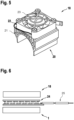
- FIG. 2 is a plan view of the base of the magnetic coil 1, which has the pin / mandrel 6.
- the electrical connection 4 is covered with a protective cap 8 which is intended to prevent the electrical connection 4 from being damaged/deformed.
- the protective cap 8 is removed before the electrical connection 4 is connected to a power source.
- FIG. 3 12 is a perspective view of a passive heat sink 10 according to a first embodiment.
- This heat sink 10 is designed as a hollow cylinder, the inside diameter of which is dimensioned such that it can be slipped over the magnetic coil 1 and clamped onto it. Thus, there is a non-positive connection between the heat sink 10 and the magnet coil 1 .
- the heat sink 10 is formed separately from the magnetic coil 1 .
- the heat sink 10 is designed as a passive cooling structure and has a large number of cooling fins 12 .
- the cooling fins 12 are formed as part of the outer surface of the heat sink 10 and extend parallel to each other in the circumferential direction thereof.
- the cooling fins 12 in Circumferentially arranged at a distance from each other.
- the first longitudinal slot 13a is designed to be continuous in the radial direction, so that it breaks through the heat sink wall.
- the second longitudinal slit 13b is provided in the radial direction as a notch in the outer wall of the heat sink and defines a predetermined bending point of the heat sink 10.
- the first longitudinal slit 13 widens when the heat sink 10 is arranged on the magnetic coil 1 and the heat sink 10 bends at the predetermined bending point, increasing its radius, in order to avoid the arranging from the heat sink 10 to the magnetic coil 1.
- the first and the second longitudinal slot 13a, 13b serve to save material on the heat sink 10 and make the heat sink 10 lighter.
- the heat sink 10 is arranged around the magnetic coil 1 and the magnetic coil 1 becomes warm, the heat is conducted to the outside via the cooling ribs 12 and given off to the environment.
- the magnetic coil 1 is thus passively cooled by conduction with the aid of the heat sink 10 .
- the heat sink 10 has a recess (not shown) which is dimensioned such that it at least partially surrounds the electrical connection 4 of the magnet coil 1 when the heat sink 10 is arranged on the outer surface 2 of the magnet coil 1.
- the height of the heat sink 10 corresponds to the height of the magnetic coil 1.
- This heat sink 14 is in the form of an (extruded) circular arc, the radius of the circular arc being dimensioned such that the heat sink 14 can be arranged on the magnetic coil 10, in particular can be clamped onto it.
- a plurality of cooling fins 16 protrude outward from the outer surface of the heat sink 14 and extend over the entire height of the heat sink 14 in the direction of its height.
- the cooling fins 16 are spaced apart from one another in a circumferential direction by a predetermined distance, optionally always the same distance, and are distributed over the circumference of the heat sink 14 .
- the cooling ribs 16 are only arranged on part of the outer peripheral surface of the heat sink 14 and are not distributed over its entire outer peripheral surface.
- the cooling fins 16 preferably all have the same dimensions.
- the Cooling body 14 designed as a passive cooling structure and dissipates heat from the magnetic coil 1 to the outside when it is placed on the magnetic coil 1 .
- the heat sink 14 is dimensioned in such a way that it only covers part of the outer surface 2 of the magnet coil 1 . In particular, the height of the heat sink 14 is less than the height of the magnetic coil 1.
- FIG. 5 a perspective view of an actively ventilated heat sink 18 according to a third embodiment.
- the heat sink 18 has a lower and an upper component 20 , 22 .
- the lower component 20 has a structure similar to that of the heat sink 14 according to the second exemplary embodiment.
- the cooling fins 21 of the lower component 20 have different depths from one another and are designed in such a way that they form a kind of flat plateau.
- the upper component 22, which is designed as a fan, is arranged on this plateau.
- the lower and the upper component 20, 22 can be connected to one another via a clamp connection, that is to say in a non-positive manner.
- the lower and the upper component can also be connected to one another in a form-fitting or material-fitting manner.
- the fan 22 is powered and has a propeller element, not shown here. If energy is supplied to the fan 22, the propeller element is set in motion, in particular in a rotational movement, and in the process generates an air movement.
- the heat sink 18 is arranged on the outer surface 2 of the magnetic coil 1 via the lower component 20 .
- the inner radius of the lower component 20 is dimensioned such that the lower component 20 can be arranged on the outer surface 2 of the magnetic coil 1, in particular can be clamped onto it (according to the same principle as the passive, arc-shaped heat sink 14). There is thus a non-positive connection between the heat sink 18 and the magnet coil 1 . If the heat sink 18 is arranged on the outer surface 2 of the magnetic coil 1 and the magnetic coil 1 or its outer surface 2 becomes warm, the lower component 20 conducts the heat from the magnetic coil 1 via the cooling fins 21 to the fan 22. The propeller element in the fan 22 moves turns (turns) and thus distributes the warm air to the surroundings.
- the heat sink 18 thus acts as an actively ventilated heat sink which can dissipate the heat generated by the magnet coil 1 by convection.
- the fan 22 can also have a frame structure 23 . This is positively connected (via fasteners) to the fan 22 via fasteners, e.g. screws.
- the frame structure 23 increases the stability of the fan 22 and protects it from impacts etc.
- the heat sink 18 has an electrical connection, not shown here, via which the fan 22 receives energy.
- the fan 22 can be supplied with energy from an external energy source.
- a heat conversion element can convert the (waste) heat from the magnet coil 1 into energy, in particular electrical energy, that can be used by the fan 22 .
- the fan 22 receives the energy required for the movement of its propeller element directly from the magnetic coil 1 via its electrical connection. If a heat conversion element is provided on the magnetic coil 1 and/or the heat sink 18, the cooling structure according to the invention is therefore separate from the outer surface 2 of the magnetic coil 1 actively ventilated, self-sufficient heat sink 18 is formed.
- FIG. 14 is a plan view of a heat conversion element, here embodied as a thermocouple 24.
- the thermocouple 24 has a metal.
- the heat conversion element may alternatively be in the form of a thermoelectric generator comprising semiconductor materials (similar to a Peltier element) rather than metal.
- thermocouple 24 is arranged between the magnetic coil 1 and the heat sink 18 according to the third embodiment. As already described above, the thermocouple 24 receives the heat (energy) from the magnetic coil 1 and converts it into electrical energy. In this case, the thermocouple 24 has an electrical connection 25 . This is connected to the electrical connection of the heat sink 18 so that the heat sink 18 can receive the electrical energy converted by the thermocouple 24 . The fan 22 can then be operated with this electrical energy. In an advantageous embodiment (not shown here), the thermocouple 24 is arranged on the plateau between the lower component 20 and the fan 22 .
- the outer surface 2 itself is designed as a cooling structure.
- the outer surface 2 is designed as a multiplicity of cooling ribs 26 which extend along the height direction of the magnet coil 1 over its entire height.
- the cooling ribs 26 are arranged in the circumferential direction with, in particular the same, distances from one another and distributed uniformly over the entire outer circumference of the magnet coil 1 .
- FIG. 8 12 is a perspective view of a solenoid valve 28 connected to two solenoid coils 1.
- the solenoid valve 28 is designed as a cuboid and has a solenoid coil 1 on each of its two short end faces.
- the magnetic coils 1 do not have a cooling structure.
- one of the heat sinks 10, 14 or 18 according to the first, second or third exemplary embodiment can be connected to the magnetic coil 1.
- the outer surface 2 of the magnetic coils 1 could itself be designed as a passive cooling structure, as is shown in 7 is shown.
- the electrical connections 4 of the two magnet coils 1 are not shown here as being connected to an energy source. However, if the solenoid valve is to be operated/actuated/switched, the electrical connection 4 of each solenoid coil 1 is connected to an energy source.
- the magnetic coil 1 generates a magnetic field/is excited by the electrical energy supplied from the energy source and thereby converts the electrical energy into magnetic energy.
- a piston (not shown) arranged in the solenoid valve 28 is moved by the magnetic field generated by the solenoid coil in such a way that a media inlet and a media outlet (both not shown) of the solenoid valve 28 are connected to one another. In this case, the solenoid valve 28 is open and a medium can flow through.
- the magnetic coil 1 If the magnetic coil 1 is no longer supplied with energy, the magnetic coil 1 no longer generates a magnetic field, so that the piston moves back into its initial position and the media inlet and media outlet of the magnetic valve 28 are again separated from one another. In this case, the solenoid valve 28 is in the closed state and no medium can flow through the solenoid valve 28 .
- the magnet coils 1 can be introduced via the pin/mandrel 6 into a corresponding recess (not shown) provided on the magnet valve 28 and thus with be connected to this.
- the magnetic coils 1 also each have an auxiliary control device 30 .
- the auxiliary control device 30 is provided at the free end of the magnetic coil 1 in each case.
- the auxiliary control device 30 also allows the solenoid valve 28 to be switched when the solenoid coil 1 is not excited/does not generate a magnetic field. The solenoid valve 28 can therefore be directly switched manually via the auxiliary control device 30 .
- the solenoid valve 28 is connected to only one solenoid coil 1.
Landscapes
- Engineering & Computer Science (AREA)
- General Engineering & Computer Science (AREA)
- Physics & Mathematics (AREA)
- Electromagnetism (AREA)
- Mechanical Engineering (AREA)
- Power Engineering (AREA)
- Electromagnets (AREA)
Applications Claiming Priority (1)
| Application Number | Priority Date | Filing Date | Title |
|---|---|---|---|
| DE102021208742.6A DE102021208742A1 (de) | 2021-08-11 | 2021-08-11 | Magnetspule mit Kühlstruktur und Magnetventil mit derartiger Magnetspule |
Publications (1)
| Publication Number | Publication Date |
|---|---|
| EP4134990A1 true EP4134990A1 (fr) | 2023-02-15 |
Family
ID=82839050
Family Applications (1)
| Application Number | Title | Priority Date | Filing Date |
|---|---|---|---|
| EP22188782.1A Pending EP4134990A1 (fr) | 2021-08-11 | 2022-08-04 | Bobine magnétique pourvue de structure de refroidissement et électrovanne dotée d'une telle bobine magnétique |
Country Status (3)
| Country | Link |
|---|---|
| EP (1) | EP4134990A1 (fr) |
| CN (1) | CN115705953A (fr) |
| DE (1) | DE102021208742A1 (fr) |
Citations (9)
| Publication number | Priority date | Publication date | Assignee | Title |
|---|---|---|---|---|
| US3818398A (en) * | 1971-11-30 | 1974-06-18 | Sporlan Valve Co | Electromagnet coil assembly |
| JPS5257964A (en) * | 1975-11-07 | 1977-05-12 | Sanmei Denki Kk | Finned electromagnet |
| US5375738A (en) * | 1993-10-27 | 1994-12-27 | Nordson Corporation | Apparatus for dispensing heated fluid materials |
| DE102007000358A1 (de) | 2006-08-01 | 2008-02-21 | Denso Corp., Kariya | Einspritzeinrichtung |
| DE102007048461A1 (de) * | 2007-10-09 | 2009-04-16 | Thomas Magnete Gmbh | Elektromagnetisches Ventil, und Verfahren zu dessen Herstellung |
| DE102009054374A1 (de) * | 2009-11-24 | 2011-05-26 | Reo Inductive Components Ag | Belastungswiderstandsanordnung |
| CN208090045U (zh) * | 2018-04-16 | 2018-11-13 | 河北大唐国际丰润热电有限责任公司 | 电磁阀线圈散热器 |
| DE102019004597A1 (de) * | 2019-07-04 | 2021-01-07 | Aventics Gmbh | Magnetventil |
| CN212718297U (zh) * | 2020-07-02 | 2021-03-16 | 斯曼特自控科技(西安)有限公司 | 一种防爆电磁阀线圈保护装置 |
Family Cites Families (4)
| Publication number | Priority date | Publication date | Assignee | Title |
|---|---|---|---|---|
| DE907910C (de) | 1943-03-27 | 1954-03-29 | Siemens Ag | Mit Kuehlrippen versehenes Gehaeuse fuer elektrische Maschinen |
| FI20085241A0 (fi) | 2008-03-20 | 2008-03-20 | Abb Oy | Menetelmä induktiivisen sähkökomponentin valmistamiseksi ja induktiivinen sähkökomponentti |
| DE102017003201B4 (de) | 2017-04-01 | 2023-11-09 | Thomas Magnete Gmbh | Elektromagnet |
| CN214579197U (zh) | 2021-04-02 | 2021-11-02 | 宁波万佳智能科技有限公司 | 一种排水阀上的安全型电磁线圈 |
-
2021
- 2021-08-11 DE DE102021208742.6A patent/DE102021208742A1/de active Pending
-
2022
- 2022-08-04 EP EP22188782.1A patent/EP4134990A1/fr active Pending
- 2022-08-10 CN CN202210956136.4A patent/CN115705953A/zh active Pending
Patent Citations (9)
| Publication number | Priority date | Publication date | Assignee | Title |
|---|---|---|---|---|
| US3818398A (en) * | 1971-11-30 | 1974-06-18 | Sporlan Valve Co | Electromagnet coil assembly |
| JPS5257964A (en) * | 1975-11-07 | 1977-05-12 | Sanmei Denki Kk | Finned electromagnet |
| US5375738A (en) * | 1993-10-27 | 1994-12-27 | Nordson Corporation | Apparatus for dispensing heated fluid materials |
| DE102007000358A1 (de) | 2006-08-01 | 2008-02-21 | Denso Corp., Kariya | Einspritzeinrichtung |
| DE102007048461A1 (de) * | 2007-10-09 | 2009-04-16 | Thomas Magnete Gmbh | Elektromagnetisches Ventil, und Verfahren zu dessen Herstellung |
| DE102009054374A1 (de) * | 2009-11-24 | 2011-05-26 | Reo Inductive Components Ag | Belastungswiderstandsanordnung |
| CN208090045U (zh) * | 2018-04-16 | 2018-11-13 | 河北大唐国际丰润热电有限责任公司 | 电磁阀线圈散热器 |
| DE102019004597A1 (de) * | 2019-07-04 | 2021-01-07 | Aventics Gmbh | Magnetventil |
| CN212718297U (zh) * | 2020-07-02 | 2021-03-16 | 斯曼特自控科技(西安)有限公司 | 一种防爆电磁阀线圈保护装置 |
Also Published As
| Publication number | Publication date |
|---|---|
| CN115705953A (zh) | 2023-02-17 |
| DE102021208742A1 (de) | 2023-02-16 |
Similar Documents
| Publication | Publication Date | Title |
|---|---|---|
| EP1926928B1 (fr) | Ensemble pour deplacer une soupape | |
| DE60205796T2 (de) | Ventile mit Schwingspulenmotor und Wärmeableitung | |
| EP2847500B1 (fr) | Électrovanne | |
| DE102008027155A1 (de) | Elektromagnetventil | |
| DE19601541A1 (de) | In einer Vakuumumgebung einsetzbares Vertikaltransfersystem sowie dazugehöriges Absperrventilsystem | |
| EP0935262A2 (fr) | Electroaimant | |
| EP2743552B1 (fr) | Soupape | |
| DE69830562T2 (de) | Spulenanordnung verwendbar in Elektromagnetventilen | |
| DE3904881A1 (de) | Elektrische scherungsbremse | |
| DE112009001025T5 (de) | Elektronisch gesteuerter Viskolüfterantrieb mit Buchse | |
| DE19636781A1 (de) | Magnetventil | |
| DE102008063534A1 (de) | Anordnung zum Verstellen eines Ventils | |
| EP3240153B1 (fr) | Système de manoeuvre | |
| EP1217273A2 (fr) | Soupape électromagnétique | |
| EP4134990A1 (fr) | Bobine magnétique pourvue de structure de refroidissement et électrovanne dotée d'une telle bobine magnétique | |
| EP2041852B1 (fr) | Interrupteur avec un accouplement pour l'organe de commande | |
| DE2458516A1 (de) | Elektromagnetische betaetigungseinrichtung | |
| DE19703321C2 (de) | Vorrichtung zur Verstellung des Stößels eines Ventils | |
| DE10236054B4 (de) | Magnetventil | |
| AT522973B1 (de) | Elektromagnetischer Aktuator | |
| WO2011138026A1 (fr) | Unité d'actionnement avec un actionneur | |
| WO2012126751A1 (fr) | Système d'actionnement pour une vanne, et vanne destinée à commander un flux gazeux et/ou liquide | |
| EP0189109A1 (fr) | Frein ou embrayage à friction | |
| EP1797640A1 (fr) | Dispositif permettant de dissiper la chaleur de machines electriques | |
| DE4037265A1 (de) | Fluessigkeitsreibungskupplung, insbesondere fuer den antrieb eines luefters zur kuehlung von kraftfahrzeugmotoren |
Legal Events
| Date | Code | Title | Description |
|---|---|---|---|
| PUAI | Public reference made under article 153(3) epc to a published international application that has entered the european phase |
Free format text: ORIGINAL CODE: 0009012 |
|
| STAA | Information on the status of an ep patent application or granted ep patent |
Free format text: STATUS: THE APPLICATION HAS BEEN PUBLISHED |
|
| AK | Designated contracting states |
Kind code of ref document: A1 Designated state(s): AL AT BE BG CH CY CZ DE DK EE ES FI FR GB GR HR HU IE IS IT LI LT LU LV MC MK MT NL NO PL PT RO RS SE SI SK SM TR |
|
| STAA | Information on the status of an ep patent application or granted ep patent |
Free format text: STATUS: REQUEST FOR EXAMINATION WAS MADE |
|
| 17P | Request for examination filed |
Effective date: 20230816 |
|
| RBV | Designated contracting states (corrected) |
Designated state(s): AL AT BE BG CH CY CZ DE DK EE ES FI FR GB GR HR HU IE IS IT LI LT LU LV MC MK MT NL NO PL PT RO RS SE SI SK SM TR |