EP4134990A1 - Magnetic coil with cooling structure and solenoid valve using the same - Google Patents
Magnetic coil with cooling structure and solenoid valve using the same Download PDFInfo
- Publication number
- EP4134990A1 EP4134990A1 EP22188782.1A EP22188782A EP4134990A1 EP 4134990 A1 EP4134990 A1 EP 4134990A1 EP 22188782 A EP22188782 A EP 22188782A EP 4134990 A1 EP4134990 A1 EP 4134990A1
- Authority
- EP
- European Patent Office
- Prior art keywords
- magnetic coil
- heat sink
- coil
- energy
- magnetic
- Prior art date
- Legal status (The legal status is an assumption and is not a legal conclusion. Google has not performed a legal analysis and makes no representation as to the accuracy of the status listed.)
- Pending
Links
Images


Classifications
-
- H—ELECTRICITY
- H01—ELECTRIC ELEMENTS
- H01F—MAGNETS; INDUCTANCES; TRANSFORMERS; SELECTION OF MATERIALS FOR THEIR MAGNETIC PROPERTIES
- H01F5/00—Coils
-
- F—MECHANICAL ENGINEERING; LIGHTING; HEATING; WEAPONS; BLASTING
- F16—ENGINEERING ELEMENTS AND UNITS; GENERAL MEASURES FOR PRODUCING AND MAINTAINING EFFECTIVE FUNCTIONING OF MACHINES OR INSTALLATIONS; THERMAL INSULATION IN GENERAL
- F16K—VALVES; TAPS; COCKS; ACTUATING-FLOATS; DEVICES FOR VENTING OR AERATING
- F16K31/00—Actuating devices; Operating means; Releasing devices
- F16K31/02—Actuating devices; Operating means; Releasing devices electric; magnetic
- F16K31/06—Actuating devices; Operating means; Releasing devices electric; magnetic using a magnet, e.g. diaphragm valves, cutting off by means of a liquid
- F16K31/0675—Electromagnet aspects, e.g. electric supply therefor
-
- F—MECHANICAL ENGINEERING; LIGHTING; HEATING; WEAPONS; BLASTING
- F16—ENGINEERING ELEMENTS AND UNITS; GENERAL MEASURES FOR PRODUCING AND MAINTAINING EFFECTIVE FUNCTIONING OF MACHINES OR INSTALLATIONS; THERMAL INSULATION IN GENERAL
- F16K—VALVES; TAPS; COCKS; ACTUATING-FLOATS; DEVICES FOR VENTING OR AERATING
- F16K49/00—Means in or on valves for heating or cooling
-
- H—ELECTRICITY
- H01—ELECTRIC ELEMENTS
- H01F—MAGNETS; INDUCTANCES; TRANSFORMERS; SELECTION OF MATERIALS FOR THEIR MAGNETIC PROPERTIES
- H01F7/00—Magnets
- H01F7/06—Electromagnets; Actuators including electromagnets
-
- H—ELECTRICITY
- H01—ELECTRIC ELEMENTS
- H01F—MAGNETS; INDUCTANCES; TRANSFORMERS; SELECTION OF MATERIALS FOR THEIR MAGNETIC PROPERTIES
- H01F27/00—Details of transformers or inductances, in general
- H01F27/02—Casings
- H01F27/025—Constructional details relating to cooling
-
- H—ELECTRICITY
- H01—ELECTRIC ELEMENTS
- H01F—MAGNETS; INDUCTANCES; TRANSFORMERS; SELECTION OF MATERIALS FOR THEIR MAGNETIC PROPERTIES
- H01F27/00—Details of transformers or inductances, in general
- H01F27/28—Coils; Windings; Conductive connections
- H01F27/2876—Cooling
Definitions
- the invention relates to a magnetic coil according to the preamble of patent claim 1 and a magnetic valve with such a magnetic coil.
- Magnetic coils can be used to convert electrical energy into magnetic energy.
- magnetic coils have a conducting wire inside them, which is arranged in a large number of windings lying on top of one another.
- a magnetic field is generated in the lead wire by the electrical energy supplied to the magnetic coil, as a result of which the magnetic coil is excited.
- the coiled wire encloses an iron core which amplifies the magnetic field generated in the wire. With the help of the magnetic field thus generated, components formed separately can be attracted and thus moved by the magnetic coil.
- a solenoid valve can be switched / actuated with the help of a solenoid coil.
- an electrical connection of a magnetic coil is connected to an energy source.
- the energy source usually in the form of a 24V voltage
- the magnetic coil generates a magnetic field and thus converts the electrical energy into magnetic energy.
- a piston arranged in the magnet valve is moved (attracted) by the magnetic field generated by the magnet coil in such a way that a media inlet and a media outlet of the magnet valve are connected to one another. In this way, the solenoid valve is opened and a medium can flow through.
- the solenoid When power is removed from the solenoid, the solenoid ceases to generate a magnetic field, so the plunger is no longer attracted to the solenoid and returns to its home position.
- the media inlet and the media outlet of the solenoid valve are separated from each other again. In this case, the solenoid valve is in the closed state and no medium can flow through the solenoid valve.
- Solenoid valves of this type which are switched by a magnetic coil, can be used, for example, as actuators for driving a valve body of an injection nozzle, as shown, inter alia, in US Pat DE 10 2007 000 358 A1 described.
- a pulse width modulation amplifier can be connected to the solenoid valve.
- the switching time of the solenoid valve is significantly reduced by the amplifier.
- the magnetic coil has to be energized for less time.
- such a method for extending the life of the magnet coil is complex and expensive.
- the invention is based on the object of providing a magnetic coil whose service life can be (further) extended.
- the service life of the magnetic coil should be extended in a simple and cost-effective manner.
- the claimed solenoid coil is designed to actuate/switch/change a valve position of a solenoid valve.
- the magnetic coil has an essentially cylindrical coil outer surface.
- the outer surface of the magnetic coil has a cooling structure which increases the outer surface.
- the energized magnetic coil heats up due to the supply of electrical energy and the heating of the magnetic coil has a negative impact on its service life. Because the outer surface of the coil has a cooling structure, the heat generated by the magnetic coil can be dissipated to the environment in a simple and uncomplicated manner. Thus, the heating effect of the magnet coil with a cooling structure on its outer surface is significantly reduced compared to a magnet coil without a cooling structure. Thus, the life of the magnet coil having a cooling structure on its outer surface can be remarkably extended compared to that of conventional magnet coils.
- the cooling structure is provided as a passive heat sink with cooling fins that is formed separately from the outer surface of the magnetic coil.
- a passive heatsink with cooling fins is easy and inexpensive to manufacture.
- the passive heat sink increases its surface area and dissipates the heat generated by the magnet coil to the environment via its cooling fins.
- the heat sink is provided separately from the magnet coil, it can be arranged on the magnet coil or removed from it as required, for example if the area around the magnet coil does not offer enough space for the heat sink.
- the heatsink can also be easily replaced.
- the passive heat sink has a hollow cylindrical shape and is arranged on the outer surface of the heat sink Cooling fins extend in the circumferential direction of the heatsink, in particular parallel to one another, and are spaced apart in the longitudinal direction of the heatsink, in particular always at the same distance, and are interrupted by at least one longitudinal slot, in particular by two diametrically opposite longitudinal slots.
- a first longitudinal slot is continuously provided in the radial direction, so that the heat sink wall surface is continuously interrupted at this point in the longitudinal direction.
- a second longitudinal slot diametrically opposite the first longitudinal slot is not provided continuously in the radial direction, but is provided as a longitudinal direction of the heat sink, in particular over the entire length of the heat sink, extending notch on the outer wall of the heat sink and serves as a predetermined bending point.
- cooling fins are distributed over the entire height/length of the hollow-cylindrical heat sink.
- Such an arrangement of the cooling ribs on the passive heat sink allows the surface area for dissipating the heat generated by the magnetic coil to be optimally enlarged.
- the height/length of the hollow-cylindrical heat sink corresponds (roughly) to the height/length of the cylindrical magnet coil.
- the entire outer surface of the magnet coil can thus be covered with cooling fins, so that the heat conduction via these cooling fins is optimal.
- the inner dimension of the hollow-cylindrical passive heat sink is smaller than the outer dimension of the magnetic coil (undersized) so that the passive heat sink can be press-fitted onto the outer surface of the coil when it is arranged and the at least one (the first) longitudinal slit widened.
- the inner dimension, in particular the inner diameter of the hollow-cylindrical heat sink is at least slightly smaller than the outer dimension, in particular the outer diameter, of the cylindrical magnetic coil. Furthermore, it is possible through the at least one longitudinal slot (as well as alternatively or additionally due to the material elasticity of the hollow-cylindrical heat sink) to reversibly expand the heat sink for arranging it on the magnetic coil. If the heat sink is arranged on the magnetic coil, the restoring force inherent in the heat sink material acts in such a way that the heat sink "encloses" the magnetic coil and is thus firmly arranged on it. Due to these features, the heat sink can be easily and securely arranged on the magnetic coil.
- the passive heat sink has a (semi-)circular shape and the cooling ribs arranged on the outer surface of the heat sink extend in the longitudinal direction of the heat sink and are spaced apart from one another in the circumferential direction of the heat sink, in particular always at the same distance.
- the cooling fins are advantageously distributed over at least part of the circumference of the heat sink.
- the cooling fins extend over the entire height / length of the arc-shaped heat sink, but are only distributed over part of the heat sink's circumference. If this passive heat sink is arranged on the magnetic coil, the cooling ribs can dissipate the heat from the magnetic coil to its surroundings particularly well due to their arrangement.
- the height/length of the circular heat sink is less than the height/length of the cylindrical magnetic coil.
- the passive heat sink only covers part of the outer surface of the coil.
- Such heat sinks in the form of a circular arc can be sufficient for cooling the magnetic coil in certain applications and are cheaper and take up less space than, for example, the passive hollow-cylindrical heat sink that covers the entire outer surface of the coil.
- the passive heat sink in the form of a circular arc if it has no cooling ribs in its end regions in the circumferential direction. In this case, these end portions can be gripped more easily and easily arranged on the magnet coil.
- the inner dimension of the (semi-) circular arc-shaped passive heat sink is smaller than an outer dimension of the magnetic coil (to an undersize) so that the passive heat sink can be press-fitted onto the outer surface of the coil when it is arranged on it.
- the inner dimension, in particular the inner radius of the (semi-)circular heat sink is at least slightly smaller than the outer dimension, in particular the outer radius, of the cylindrical magnetic coil. Due to the material elasticity of the (semi-)circular heat sink, the heat sink can be reversibly expanded for arranging it on the magnetic coil. If the heat sink is arranged on the magnetic coil, the restoring force inherent in the heat sink material acts in such a way that the heat sink "encloses" the magnetic coil and is thus firmly arranged on it. Due to these features, the heat sink can be easily and securely arranged on the magnetic coil.
- the hollow-cylindrical cooling body covering the entire outer surface of the coil and the cooling body in the form of a circular arc covering only part of the outer surface of the coil are made of metal.
- cooling structure is designed as a heat sink that is actively ventilated (actively cooling) and supplied with external energy separately from the outer surface of the magnetic coil.
- the heat sink which is arranged on the magnet coil, is an actively ventilated one (hereinafter also simply referred to as an active heat sink), it can dissipate more heat from the magnet coil to the environment compared to a passive heat sink.
- the arrangement of an active heat sink on the magnet coil is particularly useful if there is a risk of the magnet coil heating up significantly.
- the actively ventilated, externally powered heat sink has a fan that is supplied with power from a power source that is at least embodied separately from the magnetic coil.
- the active heat sink can cool the magnetic coil particularly effectively.
- the cooling structure is designed as an energy self-supply cooling body that is actively ventilated separately from the outer surface of the magnet coil.
- Energy self-sufficient here means that the active heat sink arranged on the magnetic coil receives its energy from the magnetic coil.
- the actively ventilated, energy self-supplying heat sink has a fan which is supplied with energy loss, in particular in the form of (waste) heat, from the magnetic coil.
- energy loss in particular in the form of (waste) heat
- the thermal energy from the magnetic coil can be used to drive the fan of the active heat sink.
- Such a self-sufficient active heat sink is therefore extremely energy-efficient and no energy supply from an external energy source is required.
- the actively ventilated, self-supplying heat sink (in particular its fan) is preferably supplied with a feeding signal from the magnetic coil.
- the solenoid valve or the solenoid coil and the actively ventilated, self-sufficient heat sink (or its fan) are switched on at the same time via a control signal, which puts the solenoid valve into an active / switching state.
- thermocouple or a thermoelectric generator is arranged between the magnetic coil and the heat sink, in particular between the magnetic coil and the fan, which converts the energy loss from the magnetic coil into a form of energy, in particular into an electrical voltage, which Fan of the heat sink is supplied.
- thermocouple With the help of the thermocouple or the thermoelectric generator, electrical energy (voltage) can be generated from the waste heat of the magnetic coil, which is then fed to the active, self-sufficient heat sink to drive its fan.
- the actively ventilated (externally powered or self-powered) heat sink in particular its fan, is only active (the fan rotates) when the solenoid valve or the solenoid coil is active.
- the actively ventilated (externally energy-supplied or the energy self-supplying) heat sink also cools when the magnetic valve or the magnetic coil is inactive. So there are possibilities that the actively ventilated heatsink only cools when the solenoid valve is active, and that the actively ventilated heatsink cools regardless of the solenoid valve's active state (continuously).
- a further embodiment provides that the outer surface of the magnetic coil itself is designed at least partially, in particular completely, as a cooling structure in the form of cooling ribs.
- the magnetic coil is designed as a hollow cylinder which has integrally on its outer surface, in particular on the entire outer surface, a large number of cooling ribs running in the longitudinal direction of the hollow cylinder, in particular parallel to one another and projecting outwards from the outer surface.
- the cooling fins are spaced apart from one another in the circumferential direction, in particular always at the same distance from one another.
- cooling fins which are part of (integral with) the outer surface of the magnet coil, run in the circumferential direction of the essentially cylindrical magnet coil and are spaced apart from one another in its longitudinal direction.
- the magnetic valve according to the invention has a magnetic coil as described above. Furthermore, the solenoid valve has at least one valve body, a valve seat and a closing element. The solenoid brings the closure member into contact with the valve seat and terminates contact between the closure member and the valve seat to actuate the solenoid valve between at least closed and open positions.
- the magnetic coil has a cooling structure on its outer surface that enlarges it, at least the majority of the (waste) heat generated by the magnetic coil is dissipated to the environment and the magnetic coil hardly heats up.
- the service life of this magnet coil is thus increased in comparison to one without a cooling structure, and the magnet coil according to the invention can reliably switch the magnet valve according to the invention.
- the magnetic coil 1 is a perspective view of a magnetic coil 1.
- the magnetic coil 1 is designed here as a hollow cylinder.
- the magnetic coil 1 has an outer surface 2 to which a heat sink enlarging this outer surface 2 can be attached or which itself can be designed as a cooling structure enlarging its surface.
- An electrical connection 4 protrudes from the outer surface 2 .
- the magnetic coil 1 can be connected to an (electrical) energy source, which can excite the magnetic coil 1 , via the electrical connection 4 .
- the magnet coil 1 can be connected to a magnet valve via the mandrel 6 . Solenoid coil 1 is in 1 shown without cooling structure.
- FIG. 2 is a plan view of the base of the magnetic coil 1, which has the pin / mandrel 6.
- the electrical connection 4 is covered with a protective cap 8 which is intended to prevent the electrical connection 4 from being damaged/deformed.
- the protective cap 8 is removed before the electrical connection 4 is connected to a power source.
- FIG. 3 12 is a perspective view of a passive heat sink 10 according to a first embodiment.
- This heat sink 10 is designed as a hollow cylinder, the inside diameter of which is dimensioned such that it can be slipped over the magnetic coil 1 and clamped onto it. Thus, there is a non-positive connection between the heat sink 10 and the magnet coil 1 .
- the heat sink 10 is formed separately from the magnetic coil 1 .
- the heat sink 10 is designed as a passive cooling structure and has a large number of cooling fins 12 .
- the cooling fins 12 are formed as part of the outer surface of the heat sink 10 and extend parallel to each other in the circumferential direction thereof.
- the cooling fins 12 in Circumferentially arranged at a distance from each other.
- the first longitudinal slot 13a is designed to be continuous in the radial direction, so that it breaks through the heat sink wall.
- the second longitudinal slit 13b is provided in the radial direction as a notch in the outer wall of the heat sink and defines a predetermined bending point of the heat sink 10.
- the first longitudinal slit 13 widens when the heat sink 10 is arranged on the magnetic coil 1 and the heat sink 10 bends at the predetermined bending point, increasing its radius, in order to avoid the arranging from the heat sink 10 to the magnetic coil 1.
- the first and the second longitudinal slot 13a, 13b serve to save material on the heat sink 10 and make the heat sink 10 lighter.
- the heat sink 10 is arranged around the magnetic coil 1 and the magnetic coil 1 becomes warm, the heat is conducted to the outside via the cooling ribs 12 and given off to the environment.
- the magnetic coil 1 is thus passively cooled by conduction with the aid of the heat sink 10 .
- the heat sink 10 has a recess (not shown) which is dimensioned such that it at least partially surrounds the electrical connection 4 of the magnet coil 1 when the heat sink 10 is arranged on the outer surface 2 of the magnet coil 1.
- the height of the heat sink 10 corresponds to the height of the magnetic coil 1.
- This heat sink 14 is in the form of an (extruded) circular arc, the radius of the circular arc being dimensioned such that the heat sink 14 can be arranged on the magnetic coil 10, in particular can be clamped onto it.
- a plurality of cooling fins 16 protrude outward from the outer surface of the heat sink 14 and extend over the entire height of the heat sink 14 in the direction of its height.
- the cooling fins 16 are spaced apart from one another in a circumferential direction by a predetermined distance, optionally always the same distance, and are distributed over the circumference of the heat sink 14 .
- the cooling ribs 16 are only arranged on part of the outer peripheral surface of the heat sink 14 and are not distributed over its entire outer peripheral surface.
- the cooling fins 16 preferably all have the same dimensions.
- the Cooling body 14 designed as a passive cooling structure and dissipates heat from the magnetic coil 1 to the outside when it is placed on the magnetic coil 1 .
- the heat sink 14 is dimensioned in such a way that it only covers part of the outer surface 2 of the magnet coil 1 . In particular, the height of the heat sink 14 is less than the height of the magnetic coil 1.
- FIG. 5 a perspective view of an actively ventilated heat sink 18 according to a third embodiment.
- the heat sink 18 has a lower and an upper component 20 , 22 .
- the lower component 20 has a structure similar to that of the heat sink 14 according to the second exemplary embodiment.
- the cooling fins 21 of the lower component 20 have different depths from one another and are designed in such a way that they form a kind of flat plateau.
- the upper component 22, which is designed as a fan, is arranged on this plateau.
- the lower and the upper component 20, 22 can be connected to one another via a clamp connection, that is to say in a non-positive manner.
- the lower and the upper component can also be connected to one another in a form-fitting or material-fitting manner.
- the fan 22 is powered and has a propeller element, not shown here. If energy is supplied to the fan 22, the propeller element is set in motion, in particular in a rotational movement, and in the process generates an air movement.
- the heat sink 18 is arranged on the outer surface 2 of the magnetic coil 1 via the lower component 20 .
- the inner radius of the lower component 20 is dimensioned such that the lower component 20 can be arranged on the outer surface 2 of the magnetic coil 1, in particular can be clamped onto it (according to the same principle as the passive, arc-shaped heat sink 14). There is thus a non-positive connection between the heat sink 18 and the magnet coil 1 . If the heat sink 18 is arranged on the outer surface 2 of the magnetic coil 1 and the magnetic coil 1 or its outer surface 2 becomes warm, the lower component 20 conducts the heat from the magnetic coil 1 via the cooling fins 21 to the fan 22. The propeller element in the fan 22 moves turns (turns) and thus distributes the warm air to the surroundings.
- the heat sink 18 thus acts as an actively ventilated heat sink which can dissipate the heat generated by the magnet coil 1 by convection.
- the fan 22 can also have a frame structure 23 . This is positively connected (via fasteners) to the fan 22 via fasteners, e.g. screws.
- the frame structure 23 increases the stability of the fan 22 and protects it from impacts etc.
- the heat sink 18 has an electrical connection, not shown here, via which the fan 22 receives energy.
- the fan 22 can be supplied with energy from an external energy source.
- a heat conversion element can convert the (waste) heat from the magnet coil 1 into energy, in particular electrical energy, that can be used by the fan 22 .
- the fan 22 receives the energy required for the movement of its propeller element directly from the magnetic coil 1 via its electrical connection. If a heat conversion element is provided on the magnetic coil 1 and/or the heat sink 18, the cooling structure according to the invention is therefore separate from the outer surface 2 of the magnetic coil 1 actively ventilated, self-sufficient heat sink 18 is formed.
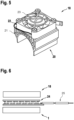
- FIG. 14 is a plan view of a heat conversion element, here embodied as a thermocouple 24.
- the thermocouple 24 has a metal.
- the heat conversion element may alternatively be in the form of a thermoelectric generator comprising semiconductor materials (similar to a Peltier element) rather than metal.
- thermocouple 24 is arranged between the magnetic coil 1 and the heat sink 18 according to the third embodiment. As already described above, the thermocouple 24 receives the heat (energy) from the magnetic coil 1 and converts it into electrical energy. In this case, the thermocouple 24 has an electrical connection 25 . This is connected to the electrical connection of the heat sink 18 so that the heat sink 18 can receive the electrical energy converted by the thermocouple 24 . The fan 22 can then be operated with this electrical energy. In an advantageous embodiment (not shown here), the thermocouple 24 is arranged on the plateau between the lower component 20 and the fan 22 .
- the outer surface 2 itself is designed as a cooling structure.
- the outer surface 2 is designed as a multiplicity of cooling ribs 26 which extend along the height direction of the magnet coil 1 over its entire height.
- the cooling ribs 26 are arranged in the circumferential direction with, in particular the same, distances from one another and distributed uniformly over the entire outer circumference of the magnet coil 1 .
- FIG. 8 12 is a perspective view of a solenoid valve 28 connected to two solenoid coils 1.
- the solenoid valve 28 is designed as a cuboid and has a solenoid coil 1 on each of its two short end faces.
- the magnetic coils 1 do not have a cooling structure.
- one of the heat sinks 10, 14 or 18 according to the first, second or third exemplary embodiment can be connected to the magnetic coil 1.
- the outer surface 2 of the magnetic coils 1 could itself be designed as a passive cooling structure, as is shown in 7 is shown.
- the electrical connections 4 of the two magnet coils 1 are not shown here as being connected to an energy source. However, if the solenoid valve is to be operated/actuated/switched, the electrical connection 4 of each solenoid coil 1 is connected to an energy source.
- the magnetic coil 1 generates a magnetic field/is excited by the electrical energy supplied from the energy source and thereby converts the electrical energy into magnetic energy.
- a piston (not shown) arranged in the solenoid valve 28 is moved by the magnetic field generated by the solenoid coil in such a way that a media inlet and a media outlet (both not shown) of the solenoid valve 28 are connected to one another. In this case, the solenoid valve 28 is open and a medium can flow through.
- the magnetic coil 1 If the magnetic coil 1 is no longer supplied with energy, the magnetic coil 1 no longer generates a magnetic field, so that the piston moves back into its initial position and the media inlet and media outlet of the magnetic valve 28 are again separated from one another. In this case, the solenoid valve 28 is in the closed state and no medium can flow through the solenoid valve 28 .
- the magnet coils 1 can be introduced via the pin/mandrel 6 into a corresponding recess (not shown) provided on the magnet valve 28 and thus with be connected to this.
- the magnetic coils 1 also each have an auxiliary control device 30 .
- the auxiliary control device 30 is provided at the free end of the magnetic coil 1 in each case.
- the auxiliary control device 30 also allows the solenoid valve 28 to be switched when the solenoid coil 1 is not excited/does not generate a magnetic field. The solenoid valve 28 can therefore be directly switched manually via the auxiliary control device 30 .
- the solenoid valve 28 is connected to only one solenoid coil 1.
Abstract
Offenbart ist eine Magnetspule, deren Außenfläche eine Kühlstruktur aufweist. Offenbart ist weiterhin ein Magnetventil, das mithilfe einer Magnetspule geschaltet wird, deren Außenfläche eine Kühlstruktur aufweist.A magnetic coil is disclosed, the outer surface of which has a cooling structure. Also disclosed is a magnetic valve that is switched using a magnetic coil whose outer surface has a cooling structure.
Description
Die Erfindung betrifft eine Magnetspule gemäß dem Oberbegriff des Patentanspruchs 1 und ein Magnetventil mit einer derartigen Magnetspule.The invention relates to a magnetic coil according to the preamble of
Magnetspulen können dazu verwendet werden, elektrische Energie in magnetische Energie umzuwandeln. Dazu weisen Magnetspulen in ihrem Inneren einen Leitungsdraht auf, der in einer Vielzahl von übereinanderliegenden Windungen angeordnet ist. In dem Leitungsdraht wird durch die der Magnetspule zugeführte elektrische Energie ein Magnetfeld erzeugt, wodurch die Magnetspule erregt wird. Häufig umschließt der gewundene Leitungsdraht einen Eisenkern, der das im Leitungsdraht erzeugte Magnetfeld verstärkt. Mithilfe von dem somit erzeugten Magnetfeld können von der Magnetspule getrennt ausgebildete Komponenten angezogen und somit bewegt werden.Magnetic coils can be used to convert electrical energy into magnetic energy. For this purpose, magnetic coils have a conducting wire inside them, which is arranged in a large number of windings lying on top of one another. A magnetic field is generated in the lead wire by the electrical energy supplied to the magnetic coil, as a result of which the magnetic coil is excited. Often the coiled wire encloses an iron core which amplifies the magnetic field generated in the wire. With the help of the magnetic field thus generated, components formed separately can be attracted and thus moved by the magnetic coil.
Diesen Mechanismus macht man sich unter anderem bei der Schaltung von Magnetventilen zu Nutze. Mithilfe einer Magnetspule kann dabei ein Magnetventil geschaltet / betätigt werden. Dazu wird ein elektrischer Anschluss einer Magnetspule mit einer Energiequelle verbunden. Mithilfe der von der Energiequelle zugeführten elektrischen Energie (üblicherweise in Form von einer 24V-Spannung) erzeugt die Magnetspule ein Magnetfeld und wandelt somit die elektrische Energie in magnetische Energie um. Ein im Magnetventil angeordneter Kolben wird von dem von der Magnetspule erzeugten Magnetfeld so bewegt (angezogen), dass ein Medieneingang und ein Medienausgang des Magnetventils miteinander in Verbindung gebracht werden. Auf diese Weise wird das Magnetventil geöffnet und ein Medium kann hindurchfließen. Wird der Magnetspule keine Energie mehr zugeführt, erzeugt die Magnetspule kein Magnetfeld mehr, sodass der Kolben nicht mehr von der Magnetspule angezogen wird und sich in seine Ausgangsstellung zurückbewegt. Dabei werden der Medieneingang und der Medienausgang des Magnetventils wieder voneinander separiert. In diesem Fall ist das Magnetventil im geschlossenen Zustand und es kann kein Medium durch das Magnetventil strömen.This mechanism is used, among other things, for switching solenoid valves. A solenoid valve can be switched / actuated with the help of a solenoid coil. For this purpose, an electrical connection of a magnetic coil is connected to an energy source. With the help of the electrical energy supplied by the energy source (usually in the form of a 24V voltage), the magnetic coil generates a magnetic field and thus converts the electrical energy into magnetic energy. A piston arranged in the magnet valve is moved (attracted) by the magnetic field generated by the magnet coil in such a way that a media inlet and a media outlet of the magnet valve are connected to one another. In this way, the solenoid valve is opened and a medium can flow through. When power is removed from the solenoid, the solenoid ceases to generate a magnetic field, so the plunger is no longer attracted to the solenoid and returns to its home position. The media inlet and the media outlet of the solenoid valve are separated from each other again. In this In this case, the solenoid valve is in the closed state and no medium can flow through the solenoid valve.
Derartige Magnetventile, die durch eine Magnetspule geschaltet werden, können bspw. als Aktoren zum Antrieb eines Ventilkörpers einer Einspritzdüse dienen, wie u.a. in der
Es hat sich in der Praxis gezeigt, dass die durchschnittliche Lebensdauer einer herkömmlichen Magnetspule häufig im Vergleich zu ihrer maximal erreichbaren Lebensdauer verkürzt ist.It has been shown in practice that the average service life of a conventional magnet coil is often shortened compared to its maximum achievable service life.
Wird das Magnetventil seltener oder kürzer geschaltet, wirkt sich dies positiv auf die Lebensdauer der Magnetspule aus. Demnach ist es in Bezug auf die Verlängerung der Lebensdauer der Magnetspule hilfreich, wenn der Energiebedarf des Magnetventils verringert wird.If the solenoid valve is switched less frequently or for a shorter period of time, this has a positive effect on the service life of the solenoid coil. Accordingly, in terms of extending the life of the solenoid coil, it is helpful if the power requirement of the solenoid valve is reduced.
Bspw. kann ein Verstärker mit Pulsweitenmodulation mit dem Magnetventil verbunden werden. Durch den Verstärker wird die Schaltzeit des Magnetventils deutlich verkürzt. Somit muss die Magnetspule weniger lang erregt werden. Dies senkt einerseits den Energiebedarf der Magnetspule bzw. des Magnetventils deutlich ab und andererseits kann dadurch die Lebensdauer der Magnetspule verlängert werden. Allerdings ist die derartige Methode zur Verlängerung der Lebensdauer der Magnetspule aufwendig und teuer.For example, a pulse width modulation amplifier can be connected to the solenoid valve. The switching time of the solenoid valve is significantly reduced by the amplifier. Thus, the magnetic coil has to be energized for less time. On the one hand, this significantly reduces the energy requirement of the magnetic coil or the magnetic valve and, on the other hand, the service life of the magnetic coil can be extended as a result. However, such a method for extending the life of the magnet coil is complex and expensive.
Demgegenüber liegt der Erfindung die Aufgabe zu Grunde, eine Magnetspule bereitzustellen, deren Lebensdauer (weiter) verlängert werden kann. Insbesondere soll die Lebensdauer der Magnetspule auf einfache Weise und kostengünstig verlängert werden.In contrast, the invention is based on the object of providing a magnetic coil whose service life can be (further) extended. In particular, the service life of the magnetic coil should be extended in a simple and cost-effective manner.
Diese Aufgabe wird hinsichtlich der Magnetspule gelöst durch die Merkmalskombination des Anspruchs 1 und hinsichtlich des Magnetventils gelöst durch die Merkmalskombination des Anspruchs 14.With regard to the magnet coil, this object is achieved by the combination of features of
Weitere vorteilhafte Ausgestaltungen der Erfindung sind in den abhängigen Ansprüchen beschrieben.Further advantageous developments of the invention are described in the dependent claims.
Die beanspruchte Magnetspule ist zur Betätigung / Schaltung / zur Änderung einer Ventilstellung von einem Magnetventil ausgelegt. Die Magnetspule weist eine im Wesentlichen zylinderförmige Spulen-Außenfläche auf. Die Außenfläche der Magnetspule weist eine die Außenfläche vergrößernde Kühlstruktur auf.The claimed solenoid coil is designed to actuate/switch/change a valve position of a solenoid valve. The magnetic coil has an essentially cylindrical coil outer surface. The outer surface of the magnetic coil has a cooling structure which increases the outer surface.
Es hat sich nämlich in der Praxis herausgestellt, dass sich die erregte Magnetspule aufgrund der Energiezufuhr mit elektrischer Energie erwärmt und das Erwärmen der Magnetspule einen negativen Einfluss auf deren Lebensdauer hat. Indem die Spulen-Außenfläche eine Kühlstruktur aufweist, kann die von der Magnetspule erzeugte Wärme einfach und unkompliziert an die Umgebung abgeführt werden. Somit wird der Erwärmungseffekt der Magnetspule mit einer Kühlstruktur an ihrer Außenfläche deutlich verringert gegenüber einer Magnetspule ohne Kühlstruktur. Somit kann die Lebensdauer der Magnetspule mit einer Kühlstruktur an ihrer Außenfläche im Vergleich zu derjenigen herkömmlicher Magnetspulen deutlich verlängert werden.It has been found in practice that the energized magnetic coil heats up due to the supply of electrical energy and the heating of the magnetic coil has a negative impact on its service life. Because the outer surface of the coil has a cooling structure, the heat generated by the magnetic coil can be dissipated to the environment in a simple and uncomplicated manner. Thus, the heating effect of the magnet coil with a cooling structure on its outer surface is significantly reduced compared to a magnet coil without a cooling structure. Thus, the life of the magnet coil having a cooling structure on its outer surface can be remarkably extended compared to that of conventional magnet coils.
In einer bevorzugten Ausführungsform ist die Kühlstruktur als separat von der Außenfläche der Magnetspule ausgebildeter, passiver Kühlkörper mit Kühlrippen vorgesehen.In a preferred embodiment, the cooling structure is provided as a passive heat sink with cooling fins that is formed separately from the outer surface of the magnetic coil.
Ein passiver Kühlkörper mit Kühlrippen ist einfach und günstig zu fertigen. Der passive Kühlkörper vergrößert in dem Zustand, in dem er an die Magnetspule angebracht ist, deren Oberfläche und leitet die von der Magnetspule erzeugte Wärme über seine Kühlrippen an die Umgebung ab. Dadurch, dass der Kühlkörper separat von der Magnetspule vorgesehen ist, kann er je nach Bedarf an der Magnetspule angeordnet werden oder auch von dieser entfernt werden, bspw. wenn die Umgebung der Magnetspule nicht genügend Platz für den Kühlkörper bietet. Der Kühlkörper kann außerdem leicht ausgetauscht werden.A passive heatsink with cooling fins is easy and inexpensive to manufacture. In the state in which it is attached to the magnet coil, the passive heat sink increases its surface area and dissipates the heat generated by the magnet coil to the environment via its cooling fins. Because the heat sink is provided separately from the magnet coil, it can be arranged on the magnet coil or removed from it as required, for example if the area around the magnet coil does not offer enough space for the heat sink. The heatsink can also be easily replaced.
Eine vorteilhafte Ausführungsform sieht vor, dass der passive Kühlkörper eine Hohlzylinderform aufweist und die an der Kühlkörperaußenfläche angeordneten Kühlrippen sich in Kühlkörper-Umfangsrichtung, insbesondere parallel zueinander, erstrecken und in Kühlkörper-Längsrichtung voneinander beabstandet sind, insbesondere immer mit demselben Abstand, und von zumindest einem Längsschlitz, insbesondere von zwei diametral gegenüberliegenden Längsschlitzen, unterbrochen sind.An advantageous embodiment provides that the passive heat sink has a hollow cylindrical shape and is arranged on the outer surface of the heat sink Cooling fins extend in the circumferential direction of the heatsink, in particular parallel to one another, and are spaced apart in the longitudinal direction of the heatsink, in particular always at the same distance, and are interrupted by at least one longitudinal slot, in particular by two diametrically opposite longitudinal slots.
Vorteilhafterweise ist dabei ein erster Längsschlitz in Radialrichtung durchgehend vorgesehen, sodass die Kühlkörper-Wandfläche an dieser Stelle in Längsrichtung durchgängig unterbrochen ist. Ein dem ersten Längsschlitz diametral gegenüberliegender zweiter Längsschlitz ist in Radialrichtung nicht durchgehend vorgesehen, sondern ist als eine sich in Kühlkörperlängsrichtung, insbesondere über die gesamte Kühlkörperlänge, erstreckende Einkerbung an der Kühlkörperaußenwand vorgesehen und dient als Sollbiegestelle. Beim Anordnen des hohlzylinderförmigen Kühlkörpers an der Magnetspule wird der erste Längsschlitz aufgeweitet und der Kühlkörper wird an der Sollbiegestelle, die durch den zweiten Längsschlitz definiert ist, aufgebogen. Wenn der Kühlkörper an der Magnetspule angeordnet ist, nimmt der Kühlkörper wieder seine hohlzylinderförmige Ursprungsform an.Advantageously, a first longitudinal slot is continuously provided in the radial direction, so that the heat sink wall surface is continuously interrupted at this point in the longitudinal direction. A second longitudinal slot diametrically opposite the first longitudinal slot is not provided continuously in the radial direction, but is provided as a longitudinal direction of the heat sink, in particular over the entire length of the heat sink, extending notch on the outer wall of the heat sink and serves as a predetermined bending point. When the hollow-cylindrical heat sink is arranged on the magnetic coil, the first longitudinal slot is widened and the heat sink is bent open at the predetermined bending point, which is defined by the second longitudinal slot. When the heat sink is arranged on the magnetic coil, the heat sink resumes its original hollow-cylindrical shape.
Dabei ist es wünschenswert, wenn die Kühlrippen über die gesamte Höhe / Länge des hohlzylinderförmigen Kühlkörpers verteilt sind. Durch die derartige Anordnung der Kühlrippen am passiven Kühlkörper kann die Oberfläche zur Abführung von der Magnetspule erzeugten Wärme optimal vergrößert werden.In this case, it is desirable if the cooling fins are distributed over the entire height/length of the hollow-cylindrical heat sink. Such an arrangement of the cooling ribs on the passive heat sink allows the surface area for dissipating the heat generated by the magnetic coil to be optimally enlarged.
Optimalerweise entspricht die Höhe / Länge des hohlzylinderförmigen Kühlkörpers (in etwa) der Höhe/ Länge der zylinderförmigen Magnetspule. Somit kann die gesamte Außenfläche der Magnetspule mit Kühlrippen bedeckt sein, sodass die Wärmeleitung über diese Kühlrippen optimal ist.Ideally, the height/length of the hollow-cylindrical heat sink corresponds (roughly) to the height/length of the cylindrical magnet coil. The entire outer surface of the magnet coil can thus be covered with cooling fins, so that the heat conduction via these cooling fins is optimal.
Weiterhin ist es vorteilhaft, wenn die Innenabmessung des hohlzylinderförmigen passiven Kühlkörpers kleiner als eine (in einem Untermaß zu einer) Außenabmessung der Magnetspule ist, sodass der passive Kühlkörper beim Anordnen an der Spulen-Außenfläche auf diese presspassbar ist und sich dabei der zumindest eine (der erste) Längsschlitz verbreitert.Furthermore, it is advantageous if the inner dimension of the hollow-cylindrical passive heat sink is smaller than the outer dimension of the magnetic coil (undersized) so that the passive heat sink can be press-fitted onto the outer surface of the coil when it is arranged and the at least one (the first) longitudinal slit widened.
Das heißt, dass die Innenabmessung, insbesondere der Innendurchmesser des hohlzylinderförmigen Kühlkörpers, zumindest geringfügig kleiner ist als die Außenabmessung, insbesondere der Außendurchmesser, der zylinderförmigen Magnetspule. Weiterhin ist es durch den zumindest einen Längsschlitz (sowie alternativ oder zusätzlich dazu aufgrund der Materialelastizität des hohlzylinderförmigen Kühlkörpers) möglich, den Kühlkörper zum Anordnen an der Magnetspule reversibel aufzudehnen. Ist der Kühlkörper an der Magnetspule angeordnet, wirkt die dem Kühlkörpermaterial innenwohnende Rückstellkraft so, dass der Kühlkörper die Magnetspule "umgreift" und somit fest an dieser angeordnet ist. Aufgrund dieser Merkmale kann der Kühlkörper einfach und sicher an der Magnetspule angeordnet werden.This means that the inner dimension, in particular the inner diameter of the hollow-cylindrical heat sink, is at least slightly smaller than the outer dimension, in particular the outer diameter, of the cylindrical magnetic coil. Furthermore, it is possible through the at least one longitudinal slot (as well as alternatively or additionally due to the material elasticity of the hollow-cylindrical heat sink) to reversibly expand the heat sink for arranging it on the magnetic coil. If the heat sink is arranged on the magnetic coil, the restoring force inherent in the heat sink material acts in such a way that the heat sink "encloses" the magnetic coil and is thus firmly arranged on it. Due to these features, the heat sink can be easily and securely arranged on the magnetic coil.
In einer alternativen, vorteilhaften Ausführungsform weist der passive Kühlkörper eine (Halb-)Kreisbogenform auf und die an der Kühlkörperaußenfläche angeordneten Kühlrippen erstrecken sich in Kühlkörper-Längsrichtung und sind in Kühlkörper-Umfangsrichtung voneinander beabstandet, insbesondere immer mit demselben Abstand. Dabei sind die Kühlrippen vorteilhafterweise zumindest über einen Teil des Kühlkörperumfangs verteilt.In an alternative advantageous embodiment, the passive heat sink has a (semi-)circular shape and the cooling ribs arranged on the outer surface of the heat sink extend in the longitudinal direction of the heat sink and are spaced apart from one another in the circumferential direction of the heat sink, in particular always at the same distance. In this case, the cooling fins are advantageously distributed over at least part of the circumference of the heat sink.
Optimalerweise erstrecken sich die Kühlrippen über die gesamte Höhe / Länge des kreisbogenförmigen Kühlkörpers, sind jedoch nur über einen Teil des Kühlkörperumfangs verteilt. Wenn dieser passive Kühlkörper an der Magnetspule angeordnet ist, können die Kühlrippen aufgrund ihrer Anordnung besonders gut die Wärme von der Magnetspule an ihre Umgebung ableiten.Optimally, the cooling fins extend over the entire height / length of the arc-shaped heat sink, but are only distributed over part of the heat sink's circumference. If this passive heat sink is arranged on the magnetic coil, the cooling ribs can dissipate the heat from the magnetic coil to its surroundings particularly well due to their arrangement.
Optimalerweise ist dabei die Höhe / Länge des kreisbogenförmigen Kühlkörpers geringer als die Höhe / Länge der zylinderförmigen Magnetspule. Damit bedeckt der passive Kühlkörper nur einen Teil der Spulen-Außenfläche. Derartige kreisbogenförmige Kühlkörper können bei bestimmten Anwendungen für die Kühlung der Magnetspule ausreichend sein und sind günstiger und nehmen weniger Platz ein, als bspw. der passive hohlzylinderförmige Kühlkörper, der die gesamte Spulen-Außenfläche bedeckt.Optimally, the height/length of the circular heat sink is less than the height/length of the cylindrical magnetic coil. This means that the passive heat sink only covers part of the outer surface of the coil. Such heat sinks in the form of a circular arc can be sufficient for cooling the magnetic coil in certain applications and are cheaper and take up less space than, for example, the passive hollow-cylindrical heat sink that covers the entire outer surface of the coil.
Es kann bei dem kreisbogenförmigen passiven Kühlkörper vorteilhaft sein, wenn er in seinen Endbereichen in Umfangsrichtung keine Kühlrippen aufweist. In diesem Fall können diese Endbereiche einfacher gegriffen und leicht an der Magnetspule angeordnet werden.It can be advantageous in the case of the passive heat sink in the form of a circular arc if it has no cooling ribs in its end regions in the circumferential direction. In this case, these end portions can be gripped more easily and easily arranged on the magnet coil.
Außerdem ist es vorteilhaft, wenn die Innenabmessung des (halb-)kreisbogenförmigen passiven Kühlkörpers kleiner als eine (in einem Untermaß zu einer) Außenabmessung der Magnetspule ist, sodass der passive Kühlkörper beim Anordnen an der Spulen-Außenfläche auf diese presspassbar ist.In addition, it is advantageous if the inner dimension of the (semi-) circular arc-shaped passive heat sink is smaller than an outer dimension of the magnetic coil (to an undersize) so that the passive heat sink can be press-fitted onto the outer surface of the coil when it is arranged on it.
Das heißt, dass die Innenabmessung, insbesondere der Innenradius des (halb-)kreisbogenförmigen Kühlkörpers, zumindest geringfügig kleiner ist als die Außenabmessung, insbesondere der Außenradius, der zylinderförmigen Magnetspule. Aufgrund der Materialelastizität des (halb-)kreisbogenförmigen Kühlkörpers kann der Kühlkörper zum Anordnen an der Magnetspule reversibel aufgedehnt werden. Ist der Kühlkörper an der Magnetspule angeordnet, wirkt die dem Kühlkörpermaterial innenwohnende Rückstellkraft so, dass der Kühlkörper die Magnetspule "umgreift" und somit fest an dieser angeordnet ist. Aufgrund dieser Merkmale kann der Kühlkörper einfach und sicher an der Magnetspule angeordnet werden.This means that the inner dimension, in particular the inner radius of the (semi-)circular heat sink, is at least slightly smaller than the outer dimension, in particular the outer radius, of the cylindrical magnetic coil. Due to the material elasticity of the (semi-)circular heat sink, the heat sink can be reversibly expanded for arranging it on the magnetic coil. If the heat sink is arranged on the magnetic coil, the restoring force inherent in the heat sink material acts in such a way that the heat sink "encloses" the magnetic coil and is thus firmly arranged on it. Due to these features, the heat sink can be easily and securely arranged on the magnetic coil.
Insbesondere sind der die gesamte Spulen-Außenfläche bedeckende hohlzylinderförmige Kühlkörper als auch der nur einen Teil der Spulen-Außenfläche bedeckende kreisbogenförmige Kühlkörper aus Metall gefertigt.In particular, the hollow-cylindrical cooling body covering the entire outer surface of the coil and the cooling body in the form of a circular arc covering only part of the outer surface of the coil are made of metal.
Eine weitere vorteilhafte Ausführungsform sieht vor, dass die Kühlstruktur als separat von der Außenfläche der Magnetspule aktiv belüfteter (aktiv kühlender), extern energieversorgter Kühlkörper ausgebildet ist.A further advantageous embodiment provides that the cooling structure is designed as a heat sink that is actively ventilated (actively cooling) and supplied with external energy separately from the outer surface of the magnetic coil.
Ist der Kühlkörper, der an der Magnetspule angeordnet ist, ein aktiv belüfteter (nachfolgend auch einfach als aktiver Kühlkörper bezeichnet), kann dieser im Vergleich zu einem passiven Kühlkörper mehr Wärme von der Magnetspule an die Umgebung abführen. Die Anordnung eines aktiven Kühlkörpers an der Magnetspule ist besonders dann sinnvoll, wenn eine starke Erwärmung der Magnetspule zu befürchten ist.If the heat sink, which is arranged on the magnet coil, is an actively ventilated one (hereinafter also simply referred to as an active heat sink), it can dissipate more heat from the magnet coil to the environment compared to a passive heat sink. The arrangement of an active heat sink on the magnet coil is particularly useful if there is a risk of the magnet coil heating up significantly.
Es ist weiterhin vorstellbar, dass der aktiv belüftete, extern energieversorgte Kühlkörper einen Lüfter aufweist, der mit Energie aus einer Energiequelle versorgt wird, die zumindest separat von der Magnetspule ausgebildet ist.It is also conceivable that the actively ventilated, externally powered heat sink has a fan that is supplied with power from a power source that is at least embodied separately from the magnetic coil.
Wenn der aktive Kühlkörper einen Lüfter aufweist, kann der aktive Kühlkörper besonders effektiv die Magnetspule kühlen.If the active heat sink has a fan, the active heat sink can cool the magnetic coil particularly effectively.
In einer besonders bevorzugten Ausführungsform ist die Kühlstruktur als separat von der Außenfläche der Magnetspule aktiv belüfteter, energieselbstversorgender Kühlkörper ausgebildet.In a particularly preferred embodiment, the cooling structure is designed as an energy self-supply cooling body that is actively ventilated separately from the outer surface of the magnet coil.
Energieselbstversorgend bedeutet hier, dass der an der Magnetspule angeordnete aktive Kühlkörper seine Energie von der Magnetspule erhält.Energy self-sufficient here means that the active heat sink arranged on the magnetic coil receives its energy from the magnetic coil.
Dabei ist es bevorzugt, wenn der aktiv belüftete, energieselbstversorgende Kühlkörper einen Lüfter aufweist, der mit einer Verlustenergie, insbesondere in Form von (Ab-)Wärme, aus der Magnetspule versorgt wird. Somit kann die Wärmeenergie aus der Magnetspule zum Antrieb des Lüfters des aktiven Kühlkörpers genutzt werden. Ein derartiger selbstversorgender aktiver Kühlkörper ist also extrem energieeffizient und es ist keine Energiezufuhr aus einer externen Energiequelle nötig.In this case, it is preferred if the actively ventilated, energy self-supplying heat sink has a fan which is supplied with energy loss, in particular in the form of (waste) heat, from the magnetic coil. In this way, the thermal energy from the magnetic coil can be used to drive the fan of the active heat sink. Such a self-sufficient active heat sink is therefore extremely energy-efficient and no energy supply from an external energy source is required.
Bevorzugterweise wird dabei der aktiv belüftete, energieselbstversorgende Kühlkörper (insbesondere dessen Lüfter) mit einem speisenden Signal aus der Magnetspule versorgt. D.h. das Magnetventil bzw. die Magnetspule und der aktiv belüftete, energieselbstversorgende Kühlkörper (bzw. dessen Lüfter) schalten sich gleichzeitig über ein Ansteuersignal ein, über das das Magnetventil in einen aktiven / schaltenden Zustand versetzt wird.In this case, the actively ventilated, self-supplying heat sink (in particular its fan) is preferably supplied with a feeding signal from the magnetic coil. This means that the solenoid valve or the solenoid coil and the actively ventilated, self-sufficient heat sink (or its fan) are switched on at the same time via a control signal, which puts the solenoid valve into an active / switching state.
Dabei ist es vorteilhaft, wenn zwischen der Magnetspule und dem Kühlkörper, insbesondere zwischen Magnetspule und Lüfter, ein Thermoelement oder ein thermoelektrischer Generator angeordnet ist, das / der die Verlustenergie aus der Magnetspule in eine Energieform, insbesondere in eine elektrische Spannung, umwandelt, die dem Lüfter des Kühlkörpers zugeführt wird.It is advantageous if a thermocouple or a thermoelectric generator is arranged between the magnetic coil and the heat sink, in particular between the magnetic coil and the fan, which converts the energy loss from the magnetic coil into a form of energy, in particular into an electrical voltage, which Fan of the heat sink is supplied.
Mithilfe von dem Thermoelement oder dem thermoelektrischen Generator kann also aus der Abwärme der Magnetspule eine elektrische Energie (Spannung) erzeugt werden, die dann dem aktiven, energieselbstversorgenden Kühlkörper zum Antrieb von dessen Lüfter zugeführt wird.With the help of the thermocouple or the thermoelectric generator, electrical energy (voltage) can be generated from the waste heat of the magnetic coil, which is then fed to the active, self-sufficient heat sink to drive its fan.
Grundsätzlich ist es denkbar, dass der aktiv belüftete (extern energieversorgte oder der energieselbstversorgende) Kühlkörper, insbesondere dessen Lüfter, nur dann aktiv ist (der Lüfter sich dreht), wenn das Magnetventil bzw. die Magnetspule aktiv ist. Allerdings ist es genauso möglich, dass der aktiv belüftete (extern energieversorgte oder der energieselbstversorgende) Kühlkörper zusätzlich dazu auch dann kühlt, wenn das Magnetventil bzw. die Magnetspule inaktiv ist. Es bestehen also die Möglichkeiten, dass der aktiv belüftete Kühlkörper nur dann kühlt, wenn das Magnetventil aktiv ist, und dass der aktiv belüftete Kühlkörper unabhängig vom Aktivitätszustand des Magnetventils (durchgängig) kühlt.In principle, it is conceivable that the actively ventilated (externally powered or self-powered) heat sink, in particular its fan, is only active (the fan rotates) when the solenoid valve or the solenoid coil is active. However, it is just as possible that the actively ventilated (externally energy-supplied or the energy self-supplying) heat sink also cools when the magnetic valve or the magnetic coil is inactive. So there are possibilities that the actively ventilated heatsink only cools when the solenoid valve is active, and that the actively ventilated heatsink cools regardless of the solenoid valve's active state (continuously).
Eine weitere Ausführungsform sieht vor, dass die Außenfläche der Magnetspule selbst zumindest teilweise, insbesondere vollständig, als Kühlstruktur in Kühlrippenform ausgebildet ist.A further embodiment provides that the outer surface of the magnetic coil itself is designed at least partially, in particular completely, as a cooling structure in the form of cooling ribs.
Dies hat den Vorteil, dass die Kühlstruktur von Anfang an in die Magnetspule integriert ist und somit nicht erst in einem zusätzlichen Montageschritt auf die Magnetspule aufgesetzt werden muss / an dieser angeordnet werden muss.This has the advantage that the cooling structure is integrated into the magnetic coil from the start and therefore does not have to be placed/arranged on the magnetic coil in an additional assembly step.
Vorteilhafterweise ist dabei die Magnetspule als Hohlzylinder ausgebildet, der an seiner Mantelaußenfläche, insbesondere auf der gesamten Mantelaußenfläche, eine Vielzahl an in Hohlzylinderlängsrichtung, insbesondere parallel zueinander, verlaufenden und von der Mantelaußenfläche nach außen ragenden Kühlrippen integral aufweist. Dabei sind die Kühlrippen in Umfangsrichtung voneinander beabstandet, insbesondere immer mit demselben Abstand zueinander.Advantageously, the magnetic coil is designed as a hollow cylinder which has integrally on its outer surface, in particular on the entire outer surface, a large number of cooling ribs running in the longitudinal direction of the hollow cylinder, in particular parallel to one another and projecting outwards from the outer surface. The cooling fins are spaced apart from one another in the circumferential direction, in particular always at the same distance from one another.
Die derartige Ausbildung der Außenfläche der Magnetspule ist im Hinblick auf eine Wärmeabführung sehr vorteilhaft.Such a design of the outer surface of the magnetic coil is very advantageous with regard to heat dissipation.
Alternativ dazu ist denkbar, dass die Kühlrippen, die ein Teil der (integral mit der) Außenfläche der Magnetspule sind, in Umfangsrichtung der im Wesentlichen zylinderförmigen Magnetspule verlaufen und in deren Längsrichtung voneinander beabstandet sind.Alternatively, it is conceivable that the cooling fins, which are part of (integral with) the outer surface of the magnet coil, run in the circumferential direction of the essentially cylindrical magnet coil and are spaced apart from one another in its longitudinal direction.
Das erfindungsgemäße Magnetventil weist eine zuvor beschriebene Magnetspule auf. Weiterhin weist das Magnetventil zumindest einen Ventilkörper, einen Ventilsitz und ein Schließelement auf. Die Magnetspule bringt das Schließelement in Kontakt mit dem Ventilsitz und beendet einen Kontakt zwischen dem Schließelement und dem Ventilsitz, um das Magnetventil zumindest zwischen einer geschlossenen und einer geöffneten Position zu betätigen.The magnetic valve according to the invention has a magnetic coil as described above. Furthermore, the solenoid valve has at least one valve body, a valve seat and a closing element. The solenoid brings the closure member into contact with the valve seat and terminates contact between the closure member and the valve seat to actuate the solenoid valve between at least closed and open positions.
Dadurch, dass die Magnetspule an ihrer Außenfläche eine diese vergrößernde Kühlstruktur aufweist, wird zumindest der Großteil der von der Magnetspule erzeugten (Ab-)Wärme an die Umgebung abgeführt und die Magnetspule heizt sich kaum auf. Somit erhöht sich die Lebensdauer dieser Magnetspule im Vergleich zu einer ohne Kühlstruktur und die erfindungsgemäße Magnetspule kann das erfindungsgemäße Magnetventil zuverlässig schalten.Because the magnetic coil has a cooling structure on its outer surface that enlarges it, at least the majority of the (waste) heat generated by the magnetic coil is dissipated to the environment and the magnetic coil hardly heats up. The service life of this magnet coil is thus increased in comparison to one without a cooling structure, and the magnet coil according to the invention can reliably switch the magnet valve according to the invention.
Mehrere Ausführungsbeispiele einer erfindungsgemäßen Magnetspule und eines Magnetventils mit einer derartigen Magnetspule sind in den Figuren dargestellt.Several exemplary embodiments of a magnetic coil according to the invention and a magnetic valve with such a magnetic coil are shown in the figures.
Es zeigen:
-
Fig. 1 eine Perspektivdarstellung einer Magnetspule; -
Fig. 2 eine Draufsicht auf eine Grundfläche der Magnetspule; -
Fig. 3 eine Perspektivdarstellung eines passiven Kühlkörpers gemäß einem ersten Ausführungsbeispiel; -
Fig. 4 eine Perspektivdarstellung eines passiven Kühlkörpers gemäß einem zweiten Ausführungsbeispiel; -
Fig. 5 eine Perspektivdarstellung eines aktiv belüfteten Kühlkörpers gemäß einem dritten Ausführungsbeispiel; -
Fig. 6 eine Draufsicht von einem Wärmeumwandlungselement, das zwischen einer Magnetspule und dem Kühlkörper gemäß dem dritten Ausführungsbeispiel angeordnet ist; -
Fig. 7 eine Perspektivdarstellung einer Magnetspule, deren Außenfläche als Kühlstruktur ausgebildet ist; und -
Fig. 8 eine Perspektivdarstellung eines Magnetventils, welches mit zwei Magnetspulen verbunden ist.
-
1 a perspective view of a magnetic coil; -
2 a plan view of a base of the magnetic coil; -
3 a perspective view of a passive heat sink according to a first embodiment; -
4 a perspective view of a passive heat sink according to a second embodiment; -
figure 5 a perspective view of an actively ventilated heat sink according to a third embodiment; -
6 14 is a plan view of a heat converting element disposed between a magnetic coil and the heat sink according to the third embodiment; -
7 a perspective view of a magnetic coil whose outer surface is designed as a cooling structure; and -
8 a perspective view of a solenoid valve, which is connected to two solenoids.
Der Kühlkörper 10 ist hierbei separat von der Magnetspule 1 ausgebildet. Der Kühlkörper 10 ist als passive Kühlstruktur ausgebildet und weist eine Vielzahl von Kühlrippen 12 auf. Die Kühlrippen 12 sind als Teil der Außenfläche des Kühlkörpers 10 ausgebildet und verlaufen parallel zueinander in dessen Umfangsrichtung. Über die gesamte Höhe des hohlzylinderförmigen Kühlkörpers 10 sind die Kühlrippen 12 in Umfangsrichtung mit einem Abstand zueinander angeordnet. Zwei diametral gegenüberliegende erste und zweite Längsschlitze 13a und 13b, die sich über die gesamte Höhe des Kühlkörpers 10 erstrecken, unterbrechen die Kühlrippen 12. Dabei ist der erste Längsschlitz 13a in Radialrichtung durchgängig ausgebildet, sodass er die Kühlkörperwand durchbricht. Der zweite Längsschlitz 13b ist in Radialrichtung als Einkerbung der Kühlkörperaußenwand vorgesehen und definiert eine Sollbiegestelle des Kühlkörpers 10. Der erste Längsschlitz 13 verbreitert sich beim Anordnen des Kühlkörpers 10 an der Magnetspule 1 und der Kühlkörper 10 biegt sich an der Sollbiegestelle radiusvergrößernd auf, um das Anordnen vom Kühlkörper 10 an der Magnetspule 1 zu erleichtern. Zusätzlich dazu dienen der erste und der zweite Längsschlitz 13a, 13b der Materialersparnis am Kühlkörper 10 und machen den Kühlkörper 10 leichter.In this case, the
Ist der Kühlkörper 10 um die Magnetspule 1 herum angeordnet und wird die Magnetspule 1 warm, wird die Wärme über die Kühlrippen 12 nach außen geleitet und an die Umgebung abgegeben. Somit wird die Magnetspule 1 mithilfe des Kühlkörpers 10 passiv durch Konduktion gekühlt. Vorteilhaft ist es, wenn der Kühlkörper 10 eine Aussparung (nicht dargestellt) aufweist, die so dimensioniert ist, dass sie den elektrischen Anschluss 4 der Magnetspule 1 zumindest teilweise umgibt, wenn der Kühlkörper 10 an der Außenfläche 2 der Magnetspule 1 angeordnet ist. Vorteilhafterweise entspricht die Höhe des Kühlkörpers 10 der Höhe der Magnetspule 1.If the
Weiterhin zeigt
Der Kühlkörper 18 wird über die untere Komponente 20 an der Außenfläche 2 der Magnetspule 1 angeordnet. Dabei ist der Innenradius der unteren Komponente 20 so bemessen, dass die untere Komponente 20 an der Außenfläche 2 der Magnetspule 1 angeordnet werden kann, insbesondere auf diese geklemmt werden kann (nach demselben Prinzip, wie der passive, kreisbogenförmige Kühlkörper 14). Zwischen dem Kühlkörper 18 und der Magnetspule 1 liegt somit eine kraftschlüssige Verbindung vor. Ist der Kühlkörper 18 an der Außenfläche 2 der Magnetspule 1 angeordnet und wird die Magnetspule 1 bzw. deren Außenfläche 2 warm, leitet die untere Komponente 20 die Wärme von der Magnetspule 1 über die Kühlrippen 21 an den Lüfter 22. Das Propellerelement im Lüfter 22 bewegt sich (dreht sich) und verteilt somit die warme Luft an die Umgebung. Damit wirkt der Kühlkörper 18 als aktiv belüfteter Kühlkörper, der die von der Magnetspule 1 erzeugte Wärme durch Konvektion ableiten kann.The
Der Lüfter 22 kann außerdem eine Rahmenstruktur 23 aufweisen. Diese wird über Befestigungsmittel, z.B. Schrauben, formschlüssig (über Befestigungsmittel) mit dem Lüfter 22 verbunden. Die Rahmenstruktur 23 erhöht die Stabilität des Lüfters 22 und schützt diesen vor Stößen etc.The
Der Kühlkörper 18 weist einen hier nicht dargestellten elektrischen Anschluss auf, über den der Lüfter 22 Energie zugeführt bekommt. Dabei kann der Lüfter 22 in einer Ausführungsform die Energie aus einer externen Energiequelle zugeführt bekommen. In einer anderen Ausführungsform kann ein Wärmeumwandlungselement die (Ab-)Wärme aus der Magnetspule 1 in eine für den Lüfter 22 nutzbare, insbesondere elektrische, Energie umwandeln. In diesem Fall erhält der Lüfter 22 über seinen elektrischen Anschluss die für die Bewegung seines Propellerelementes erforderliche Energie direkt aus der Magnetspule 1. Ist ein Wärmeumwandlungselement an der Magnetspule 1 und/oder dem Kühlkörper 18 vorgesehen, ist die erfindungsgemäße Kühlstruktur demnach als separat von der Außenfläche 2 der Magnetspule 1 aktiv belüfteter, energieselbstversorgender Kühlkörper 18 ausgebildet.The
Das Thermoelement 24 ist zwischen der Magnetspule 1 und dem Kühlkörper 18 gemäß dem dritten Ausführungsbeispiel angeordnet. Wie bereits zuvor beschrieben, erhält das Thermoelement 24 die Wärme(-energie) von der Magnetspule 1 und wandelt diese in elektrische Energie um. Dabei weist das Thermoelement 24 einen elektrischen Anschluss 25 auf. Dieser wird mit dem elektrischen Anschluss des Kühlkörpers 18 verbunden, sodass der Kühlkörper 18 die vom Thermoelement 24 umgewandelte elektrische Energie erhalten kann. Mit dieser elektrischen Energie kann dann der Lüfter 22 betrieben werden. In einer vorteilhaften Ausführungsform (hier nicht dargestellt) ist das Thermoelement 24 auf dem Plateau zwischen der unteren Komponente 20 und dem Lüfter 22 angeordnet.The
Die elektrischen Anschlüsse 4 der beiden Magnetspulen 1 sind hier nicht als mit einer Energiequelle verbunden dargestellt. Soll jedoch das Magnetventil betrieben / betätigt / geschaltet werden, wird der elektrische Anschluss 4 jeder Magnetspule 1 mit einer Energiequelle verbunden. Durch die von der Energiequelle zugeführte elektrische Energie erzeugt die Magnetspule 1 ein Magnetfeld / wird erregt und wandelt dabei die elektrische Energie in magnetische Energie um. Ein im Magnetventil 28 angeordneter Kolben (nicht dargestellt) wird von dem von der Magnetspule erzeugten Magnetfeld so bewegt, dass ein Medieneingang und ein Medienausgang (beide nicht dargestellt) des Magnetventils 28 miteinander in Verbindung gebracht werden. In diesem Fall ist das Magnetventil 28 geöffnet und ein Medium kann hindurchfließen. Wird der Magnetspule 1 keine Energie mehr zugeführt, erzeugt die Magnetspule 1 kein Magnetfeld mehr, sodass sich der Kolben in seine Ausgangsstellung zurückbewegt und dabei Medieneingang und Medienausgang des Magnetventils 28 wieder voneinander separiert. In diesem Fall ist das Magnetventil 28 im geschlossenen Zustand und es kann kein Medium durch das Magnetventil 28 strömen.The electrical connections 4 of the two
Die Magnetspulen 1 können über den Zapfen / Dorn 6 in eine entsprechende am Magnetventil 28 vorgesehene Vertiefung (nicht dargestellt) eingeführt und somit mit diesem verbunden werden. In
Bei einer alternativen Ausführungsform ist das Magnetventil 28 mit nur einer Magnetspule 1 verbunden.In an alternative embodiment, the
- 11
- Magnetspulemagnetic coil
- 22
- Außenfläche (der Magnetspule)outer surface (of the magnetic coil)
- 44
- elektrischer Anschluss (der Magnetspule)electrical connection (of the magnetic coil)
- 66
- Zapfen / Dorntenon / mandrel
- 88th
- Schutzkappeprotective cap
- 1010
- Kühlkörperheatsink
- 1212
- Kühlrippencooling fins
- 13a13a
- erster Längsschlitzfirst longitudinal slit
- 13b13b
- zweiter Längsschlitzsecond longitudinal slit
- 1414
- Kühlkörperheatsink
- 1616
- Kühlrippencooling fins
- 1818
- Kühlkörperheatsink
- 2020
- untere Komponentelower component
- 2121
- Kühlrippencooling fins
- 2222
- obere Komponente / Lüftertop component/fan
- 2323
- Rahmenstrukturframe structure
- 2424
- Thermoelement / thermoelektrischer GeneratorThermocouple / thermoelectric generator
- 2525
- elektrischer Anschluss (des Thermoelementes / des thermoelektrischen Generators)electrical connection (of the thermocouple / thermoelectric generator)
- 2626
- Kühlrippencooling fins
- 2828
- Magnetventilmagnetic valve
- 3030
- Hilfsbetätigungsvorrichtungmanual override
Claims (14)
Applications Claiming Priority (1)
| Application Number | Priority Date | Filing Date | Title |
|---|---|---|---|
| DE102021208742.6A DE102021208742A1 (en) | 2021-08-11 | 2021-08-11 | Magnetic coil with a cooling structure and magnetic valve with such a magnetic coil |
Publications (1)
| Publication Number | Publication Date |
|---|---|
| EP4134990A1 true EP4134990A1 (en) | 2023-02-15 |
Family
ID=82839050
Family Applications (1)
| Application Number | Title | Priority Date | Filing Date |
|---|---|---|---|
| EP22188782.1A Pending EP4134990A1 (en) | 2021-08-11 | 2022-08-04 | Magnetic coil with cooling structure and solenoid valve using the same |
Country Status (3)
| Country | Link |
|---|---|
| EP (1) | EP4134990A1 (en) |
| CN (1) | CN115705953A (en) |
| DE (1) | DE102021208742A1 (en) |
Citations (9)
| Publication number | Priority date | Publication date | Assignee | Title |
|---|---|---|---|---|
| US3818398A (en) * | 1971-11-30 | 1974-06-18 | Sporlan Valve Co | Electromagnet coil assembly |
| JPS5257964A (en) * | 1975-11-07 | 1977-05-12 | Sanmei Denki Kk | Finned electromagnet |
| US5375738A (en) * | 1993-10-27 | 1994-12-27 | Nordson Corporation | Apparatus for dispensing heated fluid materials |
| DE102007000358A1 (en) | 2006-08-01 | 2008-02-21 | Denso Corp., Kariya | Injection device for supplying of fuel to machine by injecting fuel, has solenoid valve and nozzle hole, where nozzle hole is opened by solenoid valve for injecting fuel |
| DE102007048461A1 (en) * | 2007-10-09 | 2009-04-16 | Thomas Magnete Gmbh | Electromagnetic valve for use in explosive atmosphere, has magnetic drive provided for driving valve piston that moves in longitudinal direction of valve, where one-chamber system is made of three-wall system |
| DE102009054374A1 (en) * | 2009-11-24 | 2011-05-26 | Reo Inductive Components Ag | Load resistor arrangement for reduction of voltage in wind power plant, has thermal element arrangement converting temperature difference into voltage for utilization of wastage energy that occurs in form of heat in load resistor |
| CN208090045U (en) * | 2018-04-16 | 2018-11-13 | 河北大唐国际丰润热电有限责任公司 | Electromagnetic valve coil radiator |
| DE102019004597A1 (en) * | 2019-07-04 | 2021-01-07 | Aventics Gmbh | magnetic valve |
| CN212718297U (en) * | 2020-07-02 | 2021-03-16 | 斯曼特自控科技(西安)有限公司 | Explosion-proof solenoid valve coil protection device |
Family Cites Families (4)
| Publication number | Priority date | Publication date | Assignee | Title |
|---|---|---|---|---|
| DE907910C (en) | 1943-03-27 | 1954-03-29 | Siemens Ag | Housing with cooling ribs for electrical machines |
| FI20085241A0 (en) | 2008-03-20 | 2008-03-20 | Abb Oy | A method of making an inductive electrical component and an inductive electrical component |
| DE102017003201B4 (en) | 2017-04-01 | 2023-11-09 | Thomas Magnete Gmbh | Electromagnet |
| CN214579197U (en) | 2021-04-02 | 2021-11-02 | 宁波万佳智能科技有限公司 | Safety electromagnetic coil on drain valve |
-
2021
- 2021-08-11 DE DE102021208742.6A patent/DE102021208742A1/en active Pending
-
2022
- 2022-08-04 EP EP22188782.1A patent/EP4134990A1/en active Pending
- 2022-08-10 CN CN202210956136.4A patent/CN115705953A/en active Pending
Patent Citations (9)
| Publication number | Priority date | Publication date | Assignee | Title |
|---|---|---|---|---|
| US3818398A (en) * | 1971-11-30 | 1974-06-18 | Sporlan Valve Co | Electromagnet coil assembly |
| JPS5257964A (en) * | 1975-11-07 | 1977-05-12 | Sanmei Denki Kk | Finned electromagnet |
| US5375738A (en) * | 1993-10-27 | 1994-12-27 | Nordson Corporation | Apparatus for dispensing heated fluid materials |
| DE102007000358A1 (en) | 2006-08-01 | 2008-02-21 | Denso Corp., Kariya | Injection device for supplying of fuel to machine by injecting fuel, has solenoid valve and nozzle hole, where nozzle hole is opened by solenoid valve for injecting fuel |
| DE102007048461A1 (en) * | 2007-10-09 | 2009-04-16 | Thomas Magnete Gmbh | Electromagnetic valve for use in explosive atmosphere, has magnetic drive provided for driving valve piston that moves in longitudinal direction of valve, where one-chamber system is made of three-wall system |
| DE102009054374A1 (en) * | 2009-11-24 | 2011-05-26 | Reo Inductive Components Ag | Load resistor arrangement for reduction of voltage in wind power plant, has thermal element arrangement converting temperature difference into voltage for utilization of wastage energy that occurs in form of heat in load resistor |
| CN208090045U (en) * | 2018-04-16 | 2018-11-13 | 河北大唐国际丰润热电有限责任公司 | Electromagnetic valve coil radiator |
| DE102019004597A1 (en) * | 2019-07-04 | 2021-01-07 | Aventics Gmbh | magnetic valve |
| CN212718297U (en) * | 2020-07-02 | 2021-03-16 | 斯曼特自控科技(西安)有限公司 | Explosion-proof solenoid valve coil protection device |
Also Published As
| Publication number | Publication date |
|---|---|
| DE102021208742A1 (en) | 2023-02-16 |
| CN115705953A (en) | 2023-02-17 |
Similar Documents
| Publication | Publication Date | Title |
|---|---|---|
| EP1926928B1 (en) | Arrangement for adjusting a valve | |
| DE102008027155B4 (en) | Solenoid valve | |
| DE60205796T2 (en) | Valves with voice coil motor and heat dissipation | |
| EP2847500B1 (en) | Solenoid valve | |
| EP0935262A2 (en) | Electromagnet | |
| DE4109978C2 (en) | Fluid friction clutch | |
| EP2743552B1 (en) | Valve | |
| DE69830562T2 (en) | Coil assembly usable in solenoid valves | |
| DE112009001025T5 (en) | Electronically controlled viscous fan drive with socket | |
| DE19636781A1 (en) | Solenoid valve | |
| EP1217273B1 (en) | Solenoid valve | |
| DE102008063534A1 (en) | Arrangement for adjusting valve, has plunger which is under action of restoring element, where valve closing unit has housing attached to valve | |
| EP3240153B1 (en) | Actuating device | |
| EP4134990A1 (en) | Magnetic coil with cooling structure and solenoid valve using the same | |
| EP2041852B1 (en) | Switch with a coupling for the actuator | |
| DE2458516A1 (en) | Electromagnetic actuator for hydraulic proportioning valve - has ring armature causing axially inclined flux to allow selection of characteristics | |
| DE10236054B4 (en) | magnetic valve | |
| DE19703321C2 (en) | Device for adjusting the tappet of a valve | |
| EP2299458B1 (en) | Electromagnet | |
| AT522973B1 (en) | Electromagnetic actuator | |
| WO2011138026A1 (en) | Operating unit having an actuator | |
| WO2012126751A1 (en) | Drive device for a valve, valve for controlling a gas and/or liquid flow | |
| EP0189109A1 (en) | Friction brake or clutch | |
| WO2006034922A1 (en) | Devices for dissipating heat from electrical machines | |
| DE102011086149A1 (en) | Holder assembly for use in brushless motor for holding piston of automobile, has magnet radially surrounded by other magnet, where poles of latter magnet are arranged behind poles of former magnet in holding position along radial direction |
Legal Events
| Date | Code | Title | Description |
|---|---|---|---|
| PUAI | Public reference made under article 153(3) epc to a published international application that has entered the european phase |
Free format text: ORIGINAL CODE: 0009012 |
|
| STAA | Information on the status of an ep patent application or granted ep patent |
Free format text: STATUS: THE APPLICATION HAS BEEN PUBLISHED |
|
| AK | Designated contracting states |
Kind code of ref document: A1 Designated state(s): AL AT BE BG CH CY CZ DE DK EE ES FI FR GB GR HR HU IE IS IT LI LT LU LV MC MK MT NL NO PL PT RO RS SE SI SK SM TR |
|
| STAA | Information on the status of an ep patent application or granted ep patent |
Free format text: STATUS: REQUEST FOR EXAMINATION WAS MADE |
|
| 17P | Request for examination filed |
Effective date: 20230816 |
|
| RBV | Designated contracting states (corrected) |
Designated state(s): AL AT BE BG CH CY CZ DE DK EE ES FI FR GB GR HR HU IE IS IT LI LT LU LV MC MK MT NL NO PL PT RO RS SE SI SK SM TR |