EP4134627B1 - Karteninformationskorrekturverfahren, fahrassistenzverfahren und karteninformationskorrekturvorrichtung - Google Patents
Karteninformationskorrekturverfahren, fahrassistenzverfahren und karteninformationskorrekturvorrichtung Download PDFInfo
- Publication number
- EP4134627B1 EP4134627B1 EP20930349.4A EP20930349A EP4134627B1 EP 4134627 B1 EP4134627 B1 EP 4134627B1 EP 20930349 A EP20930349 A EP 20930349A EP 4134627 B1 EP4134627 B1 EP 4134627B1
- Authority
- EP
- European Patent Office
- Prior art keywords
- vehicle
- region
- lane boundary
- boundary line
- map
- Prior art date
- Legal status (The legal status is an assumption and is not a legal conclusion. Google has not performed a legal analysis and makes no representation as to the accuracy of the status listed.)
- Active
Links
Images


Classifications
-
- G—PHYSICS
- G01—MEASURING; TESTING
- G01C—MEASURING DISTANCES, LEVELS OR BEARINGS; SURVEYING; NAVIGATION; GYROSCOPIC INSTRUMENTS; PHOTOGRAMMETRY OR VIDEOGRAMMETRY
- G01C21/00—Navigation; Navigational instruments not provided for in groups G01C1/00 - G01C19/00
- G01C21/38—Electronic maps specially adapted for navigation; Updating thereof
- G01C21/3804—Creation or updating of map data
- G01C21/3807—Creation or updating of map data characterised by the type of data
- G01C21/3815—Road data
- G01C21/3822—Road feature data, e.g. slope data
-
- G—PHYSICS
- G01—MEASURING; TESTING
- G01C—MEASURING DISTANCES, LEVELS OR BEARINGS; SURVEYING; NAVIGATION; GYROSCOPIC INSTRUMENTS; PHOTOGRAMMETRY OR VIDEOGRAMMETRY
- G01C21/00—Navigation; Navigational instruments not provided for in groups G01C1/00 - G01C19/00
- G01C21/38—Electronic maps specially adapted for navigation; Updating thereof
- G01C21/3804—Creation or updating of map data
- G01C21/3807—Creation or updating of map data characterised by the type of data
- G01C21/3815—Road data
-
- B—PERFORMING OPERATIONS; TRANSPORTING
- B60—VEHICLES IN GENERAL
- B60W—CONJOINT CONTROL OF VEHICLE SUB-UNITS OF DIFFERENT TYPE OR DIFFERENT FUNCTION; CONTROL SYSTEMS SPECIALLY ADAPTED FOR HYBRID VEHICLES; ROAD VEHICLE DRIVE CONTROL SYSTEMS FOR PURPOSES NOT RELATED TO THE CONTROL OF A PARTICULAR SUB-UNIT
- B60W30/00—Purposes of road vehicle drive control systems not related to the control of a particular sub-unit, e.g. of systems using conjoint control of vehicle sub-units
- B60W30/08—Active safety systems predicting or avoiding probable or impending collision or attempting to minimise its consequences
- B60W30/095—Predicting travel path or likelihood of collision
- B60W30/0956—Predicting travel path or likelihood of collision the prediction being responsive to traffic or environmental parameters
-
- B—PERFORMING OPERATIONS; TRANSPORTING
- B60—VEHICLES IN GENERAL
- B60W—CONJOINT CONTROL OF VEHICLE SUB-UNITS OF DIFFERENT TYPE OR DIFFERENT FUNCTION; CONTROL SYSTEMS SPECIALLY ADAPTED FOR HYBRID VEHICLES; ROAD VEHICLE DRIVE CONTROL SYSTEMS FOR PURPOSES NOT RELATED TO THE CONTROL OF A PARTICULAR SUB-UNIT
- B60W30/00—Purposes of road vehicle drive control systems not related to the control of a particular sub-unit, e.g. of systems using conjoint control of vehicle sub-units
- B60W30/10—Path keeping
- B60W30/12—Lane keeping
-
- G—PHYSICS
- G01—MEASURING; TESTING
- G01C—MEASURING DISTANCES, LEVELS OR BEARINGS; SURVEYING; NAVIGATION; GYROSCOPIC INSTRUMENTS; PHOTOGRAMMETRY OR VIDEOGRAMMETRY
- G01C21/00—Navigation; Navigational instruments not provided for in groups G01C1/00 - G01C19/00
- G01C21/26—Navigation; Navigational instruments not provided for in groups G01C1/00 - G01C19/00 specially adapted for navigation in a road network
- G01C21/28—Navigation; Navigational instruments not provided for in groups G01C1/00 - G01C19/00 specially adapted for navigation in a road network with correlation of data from several navigational instruments
- G01C21/30—Map- or contour-matching
- G01C21/32—Structuring or formatting of map data
-
- G—PHYSICS
- G01—MEASURING; TESTING
- G01C—MEASURING DISTANCES, LEVELS OR BEARINGS; SURVEYING; NAVIGATION; GYROSCOPIC INSTRUMENTS; PHOTOGRAMMETRY OR VIDEOGRAMMETRY
- G01C21/00—Navigation; Navigational instruments not provided for in groups G01C1/00 - G01C19/00
- G01C21/26—Navigation; Navigational instruments not provided for in groups G01C1/00 - G01C19/00 specially adapted for navigation in a road network
- G01C21/34—Route searching; Route guidance
- G01C21/36—Input/output arrangements for on-board computers
- G01C21/3626—Details of the output of route guidance instructions
- G01C21/3658—Lane guidance
-
- G—PHYSICS
- G01—MEASURING; TESTING
- G01C—MEASURING DISTANCES, LEVELS OR BEARINGS; SURVEYING; NAVIGATION; GYROSCOPIC INSTRUMENTS; PHOTOGRAMMETRY OR VIDEOGRAMMETRY
- G01C21/00—Navigation; Navigational instruments not provided for in groups G01C1/00 - G01C19/00
- G01C21/38—Electronic maps specially adapted for navigation; Updating thereof
- G01C21/3804—Creation or updating of map data
- G01C21/3833—Creation or updating of map data characterised by the source of data
- G01C21/3837—Data obtained from a single source
-
- B—PERFORMING OPERATIONS; TRANSPORTING
- B60—VEHICLES IN GENERAL
- B60W—CONJOINT CONTROL OF VEHICLE SUB-UNITS OF DIFFERENT TYPE OR DIFFERENT FUNCTION; CONTROL SYSTEMS SPECIALLY ADAPTED FOR HYBRID VEHICLES; ROAD VEHICLE DRIVE CONTROL SYSTEMS FOR PURPOSES NOT RELATED TO THE CONTROL OF A PARTICULAR SUB-UNIT
- B60W50/00—Details of control systems for road vehicle drive control not related to the control of a particular sub-unit, e.g. process diagnostic or vehicle driver interfaces
- B60W2050/0001—Details of the control system
- B60W2050/0002—Automatic control, details of type of controller or control system architecture
- B60W2050/0014—Adaptive controllers
-
- B—PERFORMING OPERATIONS; TRANSPORTING
- B60—VEHICLES IN GENERAL
- B60W—CONJOINT CONTROL OF VEHICLE SUB-UNITS OF DIFFERENT TYPE OR DIFFERENT FUNCTION; CONTROL SYSTEMS SPECIALLY ADAPTED FOR HYBRID VEHICLES; ROAD VEHICLE DRIVE CONTROL SYSTEMS FOR PURPOSES NOT RELATED TO THE CONTROL OF A PARTICULAR SUB-UNIT
- B60W2552/00—Input parameters relating to infrastructure
- B60W2552/53—Road markings, e.g. lane marker or crosswalk
-
- B—PERFORMING OPERATIONS; TRANSPORTING
- B60—VEHICLES IN GENERAL
- B60W—CONJOINT CONTROL OF VEHICLE SUB-UNITS OF DIFFERENT TYPE OR DIFFERENT FUNCTION; CONTROL SYSTEMS SPECIALLY ADAPTED FOR HYBRID VEHICLES; ROAD VEHICLE DRIVE CONTROL SYSTEMS FOR PURPOSES NOT RELATED TO THE CONTROL OF A PARTICULAR SUB-UNIT
- B60W2554/00—Input parameters relating to objects
- B60W2554/80—Spatial relation or speed relative to objects
- B60W2554/801—Lateral distance
-
- B—PERFORMING OPERATIONS; TRANSPORTING
- B60—VEHICLES IN GENERAL
- B60W—CONJOINT CONTROL OF VEHICLE SUB-UNITS OF DIFFERENT TYPE OR DIFFERENT FUNCTION; CONTROL SYSTEMS SPECIALLY ADAPTED FOR HYBRID VEHICLES; ROAD VEHICLE DRIVE CONTROL SYSTEMS FOR PURPOSES NOT RELATED TO THE CONTROL OF A PARTICULAR SUB-UNIT
- B60W2556/00—Input parameters relating to data
- B60W2556/40—High definition maps
-
- B—PERFORMING OPERATIONS; TRANSPORTING
- B60—VEHICLES IN GENERAL
- B60W—CONJOINT CONTROL OF VEHICLE SUB-UNITS OF DIFFERENT TYPE OR DIFFERENT FUNCTION; CONTROL SYSTEMS SPECIALLY ADAPTED FOR HYBRID VEHICLES; ROAD VEHICLE DRIVE CONTROL SYSTEMS FOR PURPOSES NOT RELATED TO THE CONTROL OF A PARTICULAR SUB-UNIT
- B60W2556/00—Input parameters relating to data
- B60W2556/45—External transmission of data to or from the vehicle
- B60W2556/50—External transmission of data to or from the vehicle of positioning data, e.g. GPS [Global Positioning System] data
Definitions
- the present invention relates to a map information correction method, a driving assistance method, and a map information correction device.
- a map data processing device calculates data for update from map data calculated based on a recognition result of a surrounding environment and a travel state of a vehicle and, when error between map data in a map database and the data for update is larger than a criterion value, updates the map data in the map database. Further examples of map information correction methods can be found in PTL 2 and PTL 3.
- Driving assistance control that, using map information representing positions of lane boundaries, generates a travel route based on lane boundaries in the map information and controls vehicle behavior, such as speed of a vehicle and a steering angle, in such a way as to assist travel of the vehicle along the generated travel route has been known.
- vehicle behavior such as speed of a vehicle and a steering angle
- An object of the present invention is to provide a map information correction method that is capable of preventing behavior change of a vehicle even when map information including position information of lane boundaries used in driving assistance control is corrected while the driving assistance control is in execution.
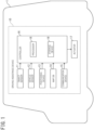
- FIG. 1 is now referred to.
- An own vehicle 1 includes a driving assistance device 10 configured to perform driving assistance of the own vehicle 1.
- the driving assistance performed by the driving assistance device 10 is self-driving control that, based on, for example, a travel environment around the own vehicle 1 and map information, causes the own vehicle 1 to self-drive without involvement of a driver.
- the driving assistance device 10 may be a device that executes driving assistance control to assist driving performed by a passenger by controlling some functions of apparatuses involved in traveling of the own vehicle 1, such as steering, accelerator opening, and a steering angle, based on a travel environment around the own vehicle 1 and map information, the following description will be made assuming, unless otherwise specifically stated, that the self-driving control that causes the own vehicle 1 to self-drive without involvement of a driver is executed.
- the driving assistance device 10 includes object sensors 11, vehicle sensors 12, a positioning device 13, a map database 14, a communication device 15, a controller 16, and actuators 17.
- the map database is denoted as "map DB”.
- the object sensors 11 include a plurality of object detection sensors of different types that are mounted on the own vehicle 1 and detect objects around the own vehicle 1, such as a laser radar, a millimeter-wave radar, a camera, and a light detection and ranging or laser imaging detection and ranging (LIDAR) .
- a laser radar a millimeter-wave radar
- a camera a camera
- a light detection and ranging or laser imaging detection and ranging (LIDAR) a light detection and ranging or laser imaging detection and ranging
- the vehicle sensors 12 are mounted on the own vehicle 1 and detects various information (vehicle signals) that can be acquired from the own vehicle 1.
- the vehicle sensors 12 include a vehicle speed sensor to detect traveling speed (vehicle speed) of the own vehicle 1, wheel speed sensors to detect rotational speeds of respective tires that the own vehicle 1 includes, a triaxial acceleration sensor (G sensor) to detect acceleration (including deceleration) of the own vehicle 1 in three axial directions, a steering angle sensor to detect a steering angle (including a turning angle), a gyro sensor to detect angular velocity generated in the own vehicle 1, a yaw rate sensor to detect a yaw rate, an accelerator sensor to detect accelerator opening of the own vehicle, and a brake sensor to detect a brake operation amount by the driver.
- G sensor triaxial acceleration sensor
- gyro sensor to detect angular velocity generated in the own vehicle 1
- a yaw rate sensor to detect a yaw rate
- an accelerator sensor to detect accelerator opening of the own vehicle
- the positioning device 13 includes a global navigation satellite system (GNSS) receiver and, by receiving radio waves from a plurality of navigation satellites, measures a current position of the own vehicle 1.
- the GNSS receiver may be, for example, a global positioning system (GPS) receiver or the like.
- the positioning device 13 may be, for example, an inertial navigation device.
- the map database 14 may store high-definition map information (hereinafter, simply referred to as "high-definition map”), which is suitable as a map for self-driving.
- the high-definition map is map data of higher precision than map data for navigation (hereinafter, simply referred to as “navigation map”) and includes information in units of lanes, which is more detailed than information in units of roads.
- a map represented by map information in the map database 14 is sometimes simply referred to as "map”.
- the high-definition map includes, as information in units of lanes, information of lane nodes that indicate reference points on a lane reference line (for example, a line at the center of a lane) and information of lane links that indicate forms of lane sections between lane nodes.
- Information of each lane node includes an identification number and position coordinates of the lane node, the number of connected lane links, and identification numbers of connected lane links.
- Information of each lane link includes an identification number of the lane link, the type of the lane, width of the lane, a shape of the lane, shapes and the types of lane boundary lines, and a shape of a lane reference line.
- the lane boundary line is a pavement marking set in place on a road surface to indicate a lane boundary, and examples of the lane boundary line includes a "roadway center line", a "lane boundary line”, and a "roadway outside line”.
- the high-definition map includes, as information of a shape of a lane, information of positions of a plurality of boundary points forming a lane boundary, and the shape of a lane boundary line is represented by a set of such boundary points.
- As information of the shape of a lane boundary line point group data representing positions on the edge of a lane-width direction edge portion of the lane boundary line may be used.
- the shape of a lane boundary line in the high-definition map is represented by a set of a plurality of boundary points forming the lane boundary, without being limited to the above, the shape of a lane boundary line may be represented by lines.
- the high-definition map further includes the types and position coordinates of ground objects, such as a traffic light, a stop line, a road sign, a building, a utility pole, a curb, and a crosswalk, that exist on a lane or in the vicinity of the lane and information of the ground objects, such as identification numbers of lane nodes and identification numbers of lane links that correspond to the position coordinates of the ground objects.
- ground objects such as a traffic light, a stop line, a road sign, a building, a utility pole, a curb, and a crosswalk
- the high-definition map includes node information and link information in units of lanes, it is possible to specify a lane in which the own vehicle 1 travels in a travel route.
- the high-definition map has a coordinate system that can represent positions in the extending direction and width direction of each lane.
- the high-definition map has coordinates (for example, longitude, latitude, and altitude) that can represent positions in the three-dimensional space, and lanes and the above-described ground objects may be described as shapes in the three-dimensional space.
- the communication device 15 performs wireless communication with a communication device external to the own vehicle 1.
- a communication method used by the communication device 15 may be, for example, wireless communication via a public mobile telephone network, vehicle-to-vehicle communication, road-to-vehicle communication, or satellite communication.
- the controller 16 is an electronic control unit (ECU) that performs driving assistance control of the own vehicle 1.
- the controller 16 controls the actuators 17 by outputting control signals to the actuators 17, based on a travel environment around the own vehicle 1, which was detected by the object sensors 11, and the map information in the map database 14, and thereby executes the self-driving control that causes the own vehicle 1 to self-drive.
- ECU electronice control unit
- the controller 16 calculates a current position (own position) of the own vehicle 1 on the map from a current position of the own vehicle 1 detected by the positioning device 13 and also sets a travel trajectory (travel trajectory represented by a relative position with respect to a lane boundary line) from the own position to a position a predetermined distance ahead, based on the own position and lane boundary lines on the map.
- the controller 16 controls, based on the own position on the map and the set travel trajectory, the own vehicle in such a way that the own vehicle 1 travels along the travel trajectory, by outputting control signals to the actuators 17 in such a way that the own position coincides with a position on the travel trajectory.
- controller 16 executes correction processing of map information of correcting lane boundary lines included in the map information in the map database 14, based on relative positions of the lane boundary lines with respect to the own vehicle, which is detected based on detection results by the object sensors 11, and the current position (own position) of the own vehicle 1. Details of the correction processing will be described later.
- the controller 16 includes a processor 18 and peripheral components, such as a storage device 19.
- the processor 18 may be, for example, a central processing unit (CPU) or a micro-processing unit (MPU).
- the storage device 19 may include a semiconductor storage device, a magnetic storage device, an optical storage device, and the like.
- the storage device 19 may include registers, a cache memory, and a memory used as a main storage device, such as a read only memory (ROM) and a random access memory (RAM) .
- ROM read only memory
- RAM random access memory
- controller 16 Functions of the controller 16, which will be described below, may be achieved by, for example, the processor 18 executing computer programs stored in the storage device 19.
- controller 16 may be formed by dedicated hardware for executing information processing that will be described below.
- the controller 16 may include a functional logic circuit that is implemented in a general-purpose semiconductor integrated circuit.
- the controller 16 may include a programmable logic device, such as a field-programmable gate array (FPGA), and the like.
- FPGA field-programmable gate array
- the actuators 17 operate a steering wheel, accelerator opening, and a braking device of the own vehicle in accordance with control signals output from the controller 16 and thereby generate vehicle behavior of the own vehicle.
- the actuators 17 include a steering actuator, an accelerator opening actuator, and brake control actuators.
- the steering actuator controls steering direction and the amount of steering of the own vehicle 1. That is, the steering actuator controls a steering mechanism.
- the accelerator opening actuator controls the accelerator opening of the own vehicle. That is, the accelerator opening actuator controls output from a power unit of the own vehicle 1.
- the brake control actuators control braking action of the braking devices of the own vehicle 1.
- the controller 16 while executing the self-driving control based on the map information in the map database 14, corrects lane boundary lines in the map information, based on a detection result in which the lane boundary lines were detected by the object sensors 11.
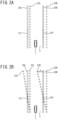
- FIG. 2A is now referred to.
- the reference sign 20L indicates a left side lane boundary line that is a lane boundary line on the left side of a lane 2 in which the own vehicle 1 travels
- the reference sign 20R indicates a right side lane boundary line that is a lane boundary line on the right side of the lane 2.
- the left side lane boundary line 20L and the right side lane boundary line 20R are sometimes collectively referred to as "lane boundary lines 20".
- a hatched portion 21L indicates a left side detection portion that is a portion of the left side lane boundary line 20L that was detected by the object sensors 11, and a hatched portion 21R indicates a right side detection portion that is a portion of the right side lane boundary line 20R that was detected by the object sensors 11.
- the left side detection portion 21L and the right side detection portion 21R are sometimes collectively referred to as "detection portions 21".
- Each of square marks 22L and square marks 22R indicate positions on the map of a plurality of boundary points forming one of the lane boundary lines of the lane 2.
- Each of the square marks 22L is a left side boundary point forming the lane boundary line on the left side of the lane 2, and each of the square marks 22R is a right side boundary point forming the lane boundary line on the right side of the lane 2.
- the left side boundary points 22L and the right side boundary points 22R are sometimes collectively referred to as "boundary points 22". Note that, since a lane boundary line is formed by a plurality of boundary points 22, it may be rephrased that a boundary point 22 is a portion of a lane boundary line. Therefore, hereinafter, a portion of a lane boundary line is sometimes represented as a boundary point 22.
- the controller 16 uses the object sensors 11, detects relative positions of the detection portions 21 with respect to the position of the own vehicle 1.
- the controller 16 using a measurement result by the positioning device 13, odometry using detection results from the vehicle sensors 12, and map matching between detection results of target objects by the object sensors 11 and the map database 14, estimates an own position of the own vehicle 1 on the map.
- the controller 16 calculates, based on the relative positions of the detection portions 21 and the own position of the own vehicle 1, positions on the map of the detection portions 21.
- the controller 16 corrects the map in the map database 14 in such a manner as to cause the positions on the map of the boundary points 22 to coincide with the actually detected positions of the detection portions 21.
- the correction of a map includes correction of a rotational component and correction of a translational component.
- FIG. 2B illustrates a case where the boundary points 22 are corrected by rotation.
- Each of round marks 23L indicates a left side corrected boundary point that is a boundary point to which a left side boundary point 22L has been corrected
- each of round marks 23R indicates a right side corrected boundary point that is a boundary point to which a right side boundary point 22R has been corrected.
- the left side corrected boundary points 23L and the right side corrected boundary points 23R are sometimes collectively referred to as "corrected boundary points 23".
- the boundary points 22 are rotated using the position of the own vehicle 1 as a reference and the corrected boundary points 23 are calculated in such a manner that differences between the corrected boundary points 23 and the detection portions 21 are minimized.
- the positions of the boundary points 22 are corrected in such a manner that the lane boundaries are rotated using the position of the own vehicle 1 as a reference.
- FIG. 3A illustrates a case where the boundary points 22 are corrected by translation.
- the controller 16 translates the boundary points 22 and calculates corrected boundary points 23 in such a manner as to minimize differences between the corrected boundary points 23 and the detection portions 21.
- the intra-lane position of the own vehicle 1 is caused to instantaneously change by the translation of the lane boundaries.
- the map is corrected while the self-driving control is in execution, there is a possibility that, in order to correct the displacement of the intra-lane position of the own vehicle 1, a rapid behavior change is caused to occur on the own vehicle 1.
- the controller 16 corrects the positions of boundary points 22 by a larger rotational correction amount in a first region 24 that is comparatively close to the own vehicle 1 than in a second region 25 that is comparatively far from the own vehicle 1, as illustrated in FIG. 3B .
- the controller 16 corrects the positions of boundary points 22 by a larger translational correction amount in the second region 25 than in the first region 24.
- the rotational correction amount becomes small.
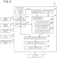
- the controller 16 includes an object detection unit 30, an own position estimation unit 31, a map acquisition unit 32, a detection integration unit 33, an object tracking unit 34, a map information correction unit 35, a driving action determination unit 36, a trajectory generation unit 37, and a vehicle control unit 38.
- the object detection unit 30 detects, based on detection signals from the object sensors 11, positions, attitudes, sizes, speeds, and the like of objects around the own vehicle 1, such as a vehicle, a motorcycle, a pedestrian, and an obstacle.
- the object detection unit 30 outputs detection results representing two-dimensional positions, attitudes, sizes, speeds, and the like of objects in, for example, a zenith view (also referred to as a plan view) in which the own vehicle 1 is viewed from the air.
- the own position estimation unit 31 measures, based on a measurement result by the positioning device 13 and odometry using detection results from the vehicle sensors 12, the own position (position on the map) of the own vehicle 1, that is, the position of the own vehicle 1 with respect to a predetermined reference point, attitude, and speed of the own vehicle 1.
- the map acquisition unit 32 acquires map information indicating a structure of a road on which the own vehicle 1 is to travel, from the map database 14.
- the map acquisition unit 32 may acquire map information from an external map data server through the communication device 15.
- the detection integration unit 33 integrates a plurality of detection results that the object detection unit 30 respectively acquired from a plurality of object detection sensors and outputs one detection result with respect to each of the respective objects.
- the detection integration unit 33 calculates, from behavior of objects respectively acquired from the object detection sensors, the most reasonable behavior of the objects that minimizes error, in consideration of error characteristics of the respective object detection sensors.
- the detection integration unit 33 comprehensively evaluates detection results acquired by a plurality of types of sensors and acquires a more accurate detection result.
- the object tracking unit 34 tracks objects detected by the object detection unit 30. Specifically, based on the detection results integrated by the detection integration unit 33, the object tracking unit 34 performs verification of identity (association) of objects between different times from behaviors of the objects output at different times and predicts, based on the association, behavior of the objects, such as speed.
- the map information correction unit 35 determines a degree of reliability of a detection result of the detection portions 21 that was detected by the detection integration unit 33 and the object tracking unit 34.
- the map information correction unit 35 may determine the degree of reliability according to deviation between the positions of the detection portions 21 detected in the previous detection and the positions of the detection portions 21 detected in the current detection.
- the map information correction unit 35 may also determine the degree of reliability according to deviation between the positions of the boundary points 22 in the map information and the positions of the detection portions 21.
- the map information correction unit 35 may determine that the degree of reliability is high when a deviation amount is less than a threshold value and determine that the degree of reliability is low when the deviation amount is greater than or equal to the threshold value.
- the map information correction unit 35 may also determine the degree of reliability according to a degree of clarity of the detection portions 21 detected by the object sensors 11.
- the map information correction unit 35 corrects, based on the detection result of the detection portions 21 and the own position of the own vehicle 1 estimated by the own position estimation unit 31, map information acquired from the map database 14.
- the map information correction unit 35 corrects the map information acquired from the external map data server.
- the map information correction unit 35 prohibits correction of the map information.
- the map information correction unit 35 includes a lane matching unit 35a, a correction parameter calculation unit 35b, and a lane correction unit 35c.
- the lane matching unit 35a identifies positions on the map corresponding to the positions of points that the object sensors 11 detected as the detection portions 21.
- the points that the object sensors 11 detected as the detection portions 21 are referred to as "detection points”.
- the points on the map corresponding to the detection points are referred to as "corresponding points”.
- the lane matching unit 35a independently identifies corresponding points with respect to each of the left side detection portion 21L and the right side detection portion 21R.
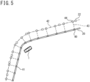
- FIG. 5 is now referred to.
- White triangle marks 40 are detection points in a detection portion 21 detected by the object sensors 11.
- Hatched triangle marks 41 are a history of detection points detected in the past.
- An alternate long and short dash line 42 is a lane boundary formed by boundary points 22 in the map information.
- the lane boundary 42 may, for example, be calculated by interpolation of the boundary points 22.
- FIG. 4 is now referred to.
- the correction parameter calculation unit 35b calculates translational correction parameters M, which are correction amounts by which boundary points 22 are corrected by translation, and rotational correction parameters R, which are correction amounts by which boundary points 22 are corrected by rotation.
- the correction parameter calculation unit 35b independently calculates, with respect to each of the left side boundary points 22L and the right side boundary points 22R, translational correction parameters M and rotational correction parameters R.
- the translational correction parameters M are translational components (tx, ty) in an affine transformation matrix expressed by, for example, the formula (1) below: [Math 1] cos ⁇ ⁇ sin ⁇ tx sin ⁇ cos ⁇ ty 0 0 1 and the rotational correction parameters Rare rotational components (cos ⁇ , -sin ⁇ , sin ⁇ , cos ⁇ ) in the affine transformation matrix.
- translational correction parameters M and the rotational correction parameters R are examples of a “translational correction amount” and a “rotational correction amount” described in the claims, respectively.
- FIG. 6A is now referred to.
- Hatched round marks 45 indicate points obtained by translating the corresponding points 44.
- the correction parameter calculation unit 35b calculates a translation amount that minimizes error between the corresponding points 45 after translation and the detection points 40 and 41 as the translational correction parameters M.
- the correction parameter calculation unit 35b calculates a translation amount that minimizes the square sum of differences in positions between the corresponding points 45 after translation and the detection points 40 and 41 as the translational correction parameters M.
- FIG. 6B is now referred to.
- Hatched round marks 46 indicate points obtained by rotating the corresponding points 44 about a rotation center C as the center.
- the correction parameter calculation unit 35b sets the rotation center C on a line representing the lane boundary 42 on the map.
- the correction parameter calculation unit 35b may set the rotation center C in such a way that the longitudinal position of the rotation center C along the lane 2 coincides with the longitudinal position of a current position O of the own vehicle 1.
- the current position O of the own vehicle 1 is only required to be, for example, any point of the own vehicle 1 and may be, for example, the central position of the own vehicle 1 or the central position of the front edge of the own vehicle 1.
- the correction parameter calculation unit 35b calculates a rotation amount ⁇ that minimizes error between the corresponding points 46 after moving and the detection points 40 and 41 and calculates rotational components (cos ⁇ , -sin ⁇ , sin ⁇ , cos ⁇ ) according to the rotation amount ⁇ , which are elements in the above-described formula (1), as the rotational correction parameters R.
- the correction parameter calculation unit 35b calculates a rotation amount ⁇ that minimizes the square sum of differences in positions between the corresponding points 46 after moving and the detection points 40 and 41 and calculates rotational components according to the rotation amount ⁇ in the above-described formula (1) as the rotational correction parameters R.
- FIG. 4 is now referred to.
- the lane correction unit 35c corrects, according to the translational correction parameters M and the rotational correction parameters R calculated by the correction parameter calculation unit 35b, the positions of the boundary points 22 included in the map information (that is, the positions of the boundary points 22 on the map).
- the lane correction unit 35c independently corrects the left side boundary points 22L and the right-side boundary points 22R.
- FIG. 7 is now referred to.
- the lane correction unit 35c corrects the positions of boundary points 22 (that is, the positions of the lane boundary lines) by a larger translational correction amount in the second region 25, which is comparatively far from the own vehicle 1, than in the first region 24, which is comparatively close to the own vehicle 1.
- the lane correction unit 35c corrects the positions of boundary points 22 (that is, the positions of the lane boundary lines) by a larger rotational correction amount in the first region 24 than in the second region 25.
- the lane correction unit 35c may set a region located ahead of the own vehicle 1 and within a first predetermined distance d1 from the current position O of the own vehicle 1 as the first region 24 and set a region located ahead of the own vehicle 1 and farther than the first predetermined distance d1 from the current position O of the own vehicle 1 as the second region 25.
- the lane correction unit 35c corrects the positions of boundary points 22 by the translational correction parameters M and does not rotate the boundary points 22.
- the lane correction unit 35c corrects boundary points 22 by the weighted sum of the rotational correction parameters R and the translational correction parameters M.
- the lane correction unit 35c determines, according to longitudinal distance x between the own vehicle 1 and a boundary point 22L1, weights of the rotational correction parameters R and the translational correction parameters M by which the boundary point 22L1 is corrected.
- the lane correction unit 35c determines the weight of the rotational correction parameters R to be larger as the longitudinal distance x is shorter.
- Performing weighting in this way causes a boundary point 22 to be corrected by a smaller translation amount as the boundary point 22 is located closer to the own vehicle 1.
- Performing weighting in this way causes a boundary point 22 to be corrected by a smaller translation amount as the boundary point 22 is located closer to the own vehicle 1.
- the lane correction unit 35c may reduce a correction amount by which the position of a boundary point 22 is translated by a larger amount as the longitudinal distance between the own vehicle 1 and the boundary point 22 is farther. Because of this configuration, it is possible to preferentially use map information in a distant region where no detection result of the lane boundary lines can be acquired.
- the lane correction unit 35c stores corrected map information in the map database 14. That is, the lane correction unit 35c updates the map database 14 with the corrected map information.
- the lane correction unit 35c updates the map information in the external map data server with the corrected map information.
- the map information correction unit 35 executes the above-described correction processing iteratively at a predetermined processing period. That is, the map information correction unit 35 acquires map information corrected and stored in the previous period from the map database 14 (or acquires the map information from the external map data server) and further corrects the acquired map information by the above-described correction processing.
- an upper limit may be set for a correction amount by which map information can be corrected in one processing period. That is, the correction parameter calculation unit 35b may limit the magnitudes of the rotational correction parameters R and the translational correction parameters M to less than or equal to a predetermined upper limit. Since, because of this configuration, excessive correction of the boundary points 22 can be avoided, even when the boundary points 22 in the map information are corrected while the self-driving control is in execution, it is possible to reduce behavior change of the own vehicle 1.
- the first predetermined distance d1 which defines length of the first region 24, may, for example, be set according to an upper limit of lateral acceleration that is allowed to be generated in the own vehicle 1 and a correction amount by which the positions of the boundary points 22 are corrected in the lateral direction. Specifically, the first predetermined distance d1 may be set according to vehicle speed of the own vehicle 1, an upper limit of lateral acceleration, and a lateral component of the translational correction parameters M.
- the first predetermined distance d1 may be set according to, in place of the lateral component of the translational correction parameters M, an upper limit of a lateral correction amount.
- the first predetermined distance d1 may be set depending on the positions of the lane boundary lines 20 detected by the object sensors 11, that is, the positions of the detection portions 21.
- FIG. 8 is now referred to.
- the lane boundary lines 20 are interrupted.
- the lane boundary lines 20 are not set in place in a range closer to the own vehicle 1 than a longitudinal position 50, and the object sensors 11 do not detect the lane boundary lines 20 in a region closer to the own vehicle 1 than the longitudinal position 50.
- the lane correction unit 35c sets a longitudinal distance from the longitudinal position 50, which is the closest position that allows the lane boundary lines 20 to be detected, to the current position O of the own vehicle 1 as the first predetermined distance d1.
- the region where the lane boundary lines 20 are not set in place can be set as the first region 24.
- the driving action determination unit 36 determines, based on detection results acquired by the detection integration unit 33 and the object tracking unit 34 and map information corrected by the map information correction unit 35, a schematic driving action of the own vehicle 1 that the driving assistance device 10 is to execute.
- Examples of the driving action that the driving action determination unit 36 determines include, for example, stopping, temporary stopping, traveling speed, deceleration, acceleration, course change, right turn, left turn, traveling straight, lane change at a merging section or between a plurality of lanes, lane keeping, overtaking, response to an obstacle of the own vehicle 1, and the like.
- the driving action determination unit 36 generates, based on the map information corrected by the map information correction unit 35 and the positions and attitudes of objects around the own vehicle 1, a route space map that represents existence or nonexistence of a route and an object around the own vehicle 1 and a risk map in which a degree of risk of a traveling field is quantified.
- the driving action determination unit 36 generates, based on the route space map and the risk map, a driving action plan of the own vehicle 1.
- the trajectory generation unit 37 generates, based on a driving action determined by the driving action determination unit 36, motion characteristics of the own vehicle 1, and the route space map, candidates of a travel trajectory (a travel trajectory represented by relative positions with respect to the lane boundary lines 20) along which and a speed profile in accordance with which the own vehicle 1 is caused to travel.
- the trajectory generation unit 37 evaluates future risks of the respective candidates, based on the risk map, selects an optimum travel trajectory and speed profile, and sets the selected travel trajectory and speed profile as a target travel trajectory along which and a target speed profile in accordance with which the own vehicle 1 is caused to travel, respectively.
- the vehicle control unit 38 drives the actuators 17 in such a way that the own vehicle 1 travels along the target travel trajectory at a speed in accordance with the target speed profile generated by the trajectory generation unit 37.
- step S1 the object detection unit 30, using a plurality of object detection sensors, detects relative positions with respect to the own vehicle 1, attitudes, sizes, speeds, and the like of objects, including lane boundary lines, around the own vehicle 1.
- step S2 the detection integration unit 33 integrates a plurality of detection results acquired respectively from a plurality of object detection sensors and outputs one detection result with respect to each of the respective objects.
- the object tracking unit 34 tracks the respective objects that were detected and integrated and predicts behavior of the objects around the own vehicle 1. In this processing, the positions of the lane boundary lines 20, which are set in place on the road surface around the own vehicle 1, are detected.
- step S3 the map acquisition unit 32 acquires map information indicating a structure of a road on which the own vehicle 1 is to travel.
- step S4 the own position estimation unit 31 measures, based on a measurement result by the positioning device 13 and odometry using detection results from the vehicle sensors 12, the position, attitude, and speed of the own vehicle 1 with respect to a predetermined reference point.
- step S5 the map information correction unit 35 determines whether or not the degree of reliability of a detection result of the detection portions 21 of the lane boundary lines 20 is high.
- step S6 the degree of reliability is not high (step S5: N)
- step S9 the degree of reliability is not high (step S5: N)
- step S6 the lane matching unit 35a executes matching processing.
- the lane matching unit 35a identifies positions on the map (corresponding points 44) corresponding to points that the object sensors 11 detected as the detection portions 21.
- step S7 the correction parameter calculation unit 35b calculates translational correction parameters M and rotational correction parameters R.
- step S8 the lane correction unit 35c corrects, according to the translational correction parameters M and the rotational correction parameters R, the positions of the boundary points 22 included in the map information (that is, the positions of the boundary points 22 on the map).
- step S9 the driving action determination unit 36 determines a driving action, based on detection results acquired by the detection integration unit 33 and the object tracking unit 34 and the map information corrected by the map information correction unit 35.
- the trajectory generation unit 37 generates, based on the driving action determined by the driving action determination unit 36, motion characteristics of the own vehicle 1, and the map information corrected by the map information correction unit 35, a target travel trajectory along which and a target speed profile in accordance with which the own vehicle 1 is caused to travel.
- step S5 N
- steps S6 to S8 in which the map information is corrected, are skipped, map information that had been corrected up until the previous period is used in step S9.
- step S11 whether or not an ignition switch (IGN) of the own vehicle 1 has been turned off is determined.
- the ignition switch has not been turned off (step S11: N)
- the process returns to step S1.
- the ignition switch has been turned off (step S11: Y)
- the process is terminated.
- the translational correction amount becomes small, even when the lane boundary lines formed by the boundary points 22 in the map information are corrected while the self-driving control is in execution, it is possible to reduce behavior change of the own vehicle 1.
- the rotational correction amount and the translational correction amount may be weighted according to longitudinal distance in such a manner that the weight of the rotational correction amount becomes larger as the longitudinal distance between the own vehicle 1 and a boundary point 22 is shorter (for a part of a lane boundary line having a shorter longitudinal distance from the own vehicle 1).
- a boundary point 22 closer to the own vehicle 1 (a part of a lane boundary line closer to the own vehicle 1) is corrected by a smaller translation amount.
- a boundary point 22 closer to the own vehicle 1 is corrected by a smaller translation amount.
- the lane correction unit 35c may set a region located ahead of the own vehicle 1 and within the first predetermined distance d1 from the position of the own vehicle 1 as the first region 24 and set a region located ahead of the own vehicle 1 and farther than the first predetermined distance d1 from the position of the own vehicle 1 as the second region 25.
- the lane correction unit 35c may set the first predetermined distance d1 according to an upper limit of lateral acceleration that is generated in the own vehicle 1 and a correction amount by which the positions of the boundary points 22 (lane boundary lines) are corrected in the lateral direction.
- the lane correction unit 35c may set the first predetermined distance d1 depending on the positions of the detected lane boundary lines 20.
- the lane correction unit 35c may, in a region located ahead of and farther than a range in which the positions of the lane boundary lines 20 are detected, reduce a correction amount of the position of a boundary point 22 by a larger amount as the longitudinal distance between the own vehicle 1 and the boundary point 22 is farther.
- the lane correction unit 35c may independently correct the positions of boundary points 22 on the right side of the lane and the positions of boundary points 22 on the left side of the lane. Because of this configuration, even when distance between the actually detected left side lane boundary line 20L and right side lane boundary line 20R differs from a lane width on the map, it is possible to appropriately correct the left side boundary points 22L and the right side boundary points 22R depending on detection positions that are actually detected as the left side lane boundary line 20L and the right side lane boundary line 20R.
- a map information correction unit 35 of the second embodiment corrects positions of lane boundary lines (boundary points 22) by only a rotational correction amount in a first region 24 and only a translational correction amount in a second region 25.
- FIG. 10A is now referred to.
- a lane correction unit 35c corrects the positions of boundary points 22 by translational correction parameters M and does not rotate the boundary points 22.
- the lane correction unit 35c determines rotation angles of boundary points 22 in the first region 24 in such a way that lane boundaries in the first region 24 and lane boundaries in the second region 25, which are formed by corrected boundary points 23, connect to each other at a boundary position between the first region 24 and the second region 25.
- first predetermined distance d1 that is, length of the first region 24
- first predetermined distance d1 may be adjusted in such a way that the lane boundaries in the first region 24 and the lane boundaries in the second region 25 connect to each other at the boundary position between the first region 24 and the second region 25.
- the lane correction unit 35c corrects the positions of the boundary points 22 by only the rotational correction amount in the first region 24 and only the translational correction amount in the second region 25.
- the lane correction unit 35c may correct the positions of the boundary points 22 by rotating the positions of boundary points 22 in the first region 24 in such a way that the lane boundaries in the first region 24 and the lane boundaries in the second region 25 connect to each other.
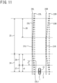
- a region that is comparatively close to an own vehicle 1 and a region that is comparatively far from the own vehicle 1 are defined in a first region 24, and positions of boundary points 22 are, as with the second embodiment, corrected by only a rotational correction amount in the comparatively close region and the rotational correction amount and a translational correction amount are, as with the first embodiment, weighted in the comparatively far region.
- the first region 24 includes a third region 27 that is a region located ahead of the own vehicle 1 and within a second predetermined distance d2 from the position of the own vehicle 1 and a fourth region 28 that is a region located ahead of the own vehicle 1 and farther than the second predetermined distance d2 from the position of the own vehicle 1.
- a lane correction unit 35c corrects the positions of boundary points 22 by only rotation using rotational correction parameters R.
- the lane correction unit 35c corrects boundary points 22 using the weighted sum of the rotational correction parameters R and translational correction parameters M.
- the lane correction unit 35c may, for example, determine weights of the rotational correction parameters R and the translational correction parameters M by which a boundary point 22L1 is corrected, in such a manner that the weight of the rotational correction parameter R becomes larger as longitudinal distance between the own vehicle 1 and the boundary point 22L1 is shorter.
- the lane correction unit 35c may correct the boundary point 22L1 by, for example, a correction amount calculated by the formula (3) below.
- Correction amount d 3 ⁇ x / d 3 ⁇ R + x / d 3 ⁇ M Amended description page for entry into European phase
- the first region 24 includes the third region 27 that is a region located ahead of the own vehicle 1 and within the second predetermined distance d2 from the position of the own vehicle 1 and the fourth region 28 that is a region located ahead of the own vehicle 1 and farther than the second predetermined distance d2 from the position of the own vehicle 1.
- the lane correction unit 35c corrects the positions of boundary points 22 by only the rotational correction amount.
- the rotational correction amount and the translational correction amount are weighted according to longitudinal distance in such a manner that the weight of the rotational correction amount becomes larger as the longitudinal distance between the own vehicle 1 and a boundary point 22 is shorter.
Landscapes
- Engineering & Computer Science (AREA)
- Radar, Positioning & Navigation (AREA)
- Remote Sensing (AREA)
- Automation & Control Theory (AREA)
- Physics & Mathematics (AREA)
- General Physics & Mathematics (AREA)
- Transportation (AREA)
- Mechanical Engineering (AREA)
- Traffic Control Systems (AREA)
- Navigation (AREA)
- Control Of Driving Devices And Active Controlling Of Vehicle (AREA)
Claims (11)
- Ein Karteninformationskorrekturverfahren, um Karteninformationen einer Karte eines eigenen Fahrzeugs (1) zu korrigieren, einschließlich Informationen einer Fahrspurgrenzlinie (22L, 22R), die in einer Fahrassistenzfunktion verwendet werden, um eine Fahrspur auf Basis der Fahrspurgrenzinformationen zu erzeugen und das eigene Fahrzeug (1) zu steuern, um die Fahrt des eigenen Fahrzeugs (1) entlang der erzeugten Fahrspur zu unterstützen, wobei das Verfahren umfasst:Erfassen einer Position einer Fahrspurgrenzlinie (20L, 20R) in Bezug auf das eigene Fahrzeug (1), die auf einer Straßenoberfläche um das eigene Fahrzeug (1) herum angebracht ist;Schätzen einer eigenen Position auf der Karte des eigenen Fahrzeugs (1); undBerechnen von Translationskorrekturparametern (M), die Korrekturbeträge sind, um die Grenzpunkte (22) der Fahrspurgrenzlinie (22L, 22R) der Karte durch Translation korrigiert werden, und Rotationskorrekturparametern (R), die Korrekturbeträge sind, um die Grenzpunkte (22) der Fahrspurgrenzlinie (22L, 22R) der Karte durch Rotation korrigiert werden; wobeidie Rotation eine Rotation um ein Rotationszentrum (C) ist, das auf der Fahrspurgrenzlinie (22L, 22R) der Karte festgelegt ist;wobei das Verfahren dadurch gekennzeichnet ist, dass es ferner umfasst:Korrigieren einer Position der Fahrspurgrenzlinie (22L, 22R), die , die in den Karteninformationen enthalten ist, durch einen größeren Rotationskorrekturbetrag in einem ersten Bereich (24) als in einem zweiten Bereich (25) und durch einen größeren Translationskorrekturbetrag in dem zweiten Bereich (25) als in dem ersten Bereich (25); wobeider erste Bereich (24) ein Bereich ist, der sich vor dem eigenen Fahrzeug (1) und innerhalb einer vorbestimmten Entfernung von einer Position des eigenen Fahrzeugs (1) befindet, und der zweite Bereich (25) ein Bereich ist, der sich vor dem eigenen Fahrzeug (1) und weiter als die vorbestimmte Entfernung von einer Position des eigenen Fahrzeugs (1) befindet; undjeder der Translationskorrekturbeträge und der Rotationskorrekturbeträge einen Fehler zwischen entsprechenden Punkten der Fahrspurgrenzlinie (23L, 23R), die nach dem Bewegen der Fahrspurgrenzlinie (22L, 22R) der Karte erhalten werden, und der erfassten Position der Fahrspurgrenzlinie (20L, 20R) minimiert.
- Das Karteninformationskorrekturverfahren nach Anspruch 1, wobei das Verfahren in dem ersten Bereich (24) den Rotationskorrekturbetrag und den Translationskorrekturbetrag gemäß der Längsdistanz gewichtet, so dass ein Gewicht des Rotationskorrekturbetrags für die Fahrspurgrenzlinie (22L, 22R) an einer Position mit einer kürzeren Längsdistanz von dem eigenen Fahrzeug (1) größer wird.
- Das Karteninformationskorrekturverfahren nach Anspruch 1, wobei das Verfahren eine Position der Fahrspurgrenzlinie (22L, 22R) nur um den Rotationskorrekturbetrag in dem ersten Bereich (24) und nur um den Translationskorrekturbetrag in dem zweiten Bereich (25) korrigiert.
- Das Karteninformationskorrekturverfahren nach Anspruch 3, wobei das Verfahren eine Position der Fahrspurgrenzlinie (22L, 22R) durch Drehen einer Position der Fahrspurgrenzlinie (22L, 22R) in dem ersten Bereich (24) auf eine solche Weise korrigiert, dass eine Fahrspurgrenzlinie (22L, 22R) in dem ersten Bereich (24) und eine Fahrspurgrenzlinie (22L, 22R) in dem zweiten Bereich (25) miteinander verbunden werden.
- Das Karteninformationskorrekturverfahren gemäß einem der Ansprüche 1 bis 4, wobeider erste Bereich (24) einen dritten Bereich, wobei der dritte Bereich ein Bereich ist, der vor dem eigenen Fahrzeug (1) und innerhalb einer zweiten vorbestimmten Entfernung von einer Position des eigenen Fahrzeugs (1) angeordnet ist, und einen vierten Bereich umfasst, wobei der vierte Bereich ein Bereich ist, der vor dem eigenen Fahrzeug (1) und weiter als die zweite vorbestimmte Entfernung von einer Position des eigenen Fahrzeugs (1) angeordnet ist;in dem dritten Bereich korrigiert das Verfahren eine Position der Fahrspurgrenzlinie (22L, 22R) nur um den Rotationskorrekturbetrag; undim vierten Bereich gewichtet das Verfahren den Rotationskorrekturbetrag und den Translationskorrekturbetrag gemäß der Längsdistanz derart, dass ein Gewicht des Rotationskorrekturbetrags für die Fahrspurgrenzlinie (22L, 22R) an einer Position mit einer kürzeren Längsdistanz vom eigenen Fahrzeug (1) größer wird.
- Das Karteninformationskorrekturverfahren gemäß einem der Ansprüche 1 bis 5, wobei das Verfahren die vorbestimmte Distanz gemäß einer Obergrenze der in dem eigenen Fahrzeug (1) erzeugten Querbeschleunigung und einen Korrekturbetrag festlegt, um den eine Position der Fahrspurgrenzlinie (22L, 22R) in einer Querrichtung korrigiert wird.
- Das Karteninformationskorrekturverfahren gemäß einem der Ansprüche 1 bis 5, wobei das Verfahren den vorbestimmten Abstand in Abhängigkeit von einem Längsabstand von einer nächstgelegenen Position, die die Erfassung der Fahrspurgrenzlinien (20L, 20R) ermöglicht, zu einer aktuellen Position des eigenen Fahrzeugs (1) einstellt.
- Das Karteninformationskorrekturverfahren gemäß einem der Ansprüche 1 bis 7, wobei das Verfahren in einem Bereich, der sich vor und weiter als ein Bereich befindet, in dem eine Position der Fahrspurgrenzlinie (20L, 20R) erfasst wird, einen Korrekturbetrag einer Position des Grenzpunkts um einen größeren Betrag für die Fahrspurgrenzlinie (22L, 22R) an einer Position verringert, die einen größeren Längsabstand vom eigenen Fahrzeug (1) aufweist.
- Das Karteninformationskorrekturverfahren gemäß einem der Ansprüche 1 bis 7, wobei das Verfahren unabhängig eine Position der Fahrspurgrenzlinie (22L) auf einer rechten Seite einer Fahrspur und eine Position der Fahrspurgrenzlinie (22R) auf einer linken Seite der Fahrspur korrigiert.
- Ein Fahrassistenzverfahren, das alle Schritte des Karteninformationskorrekturverfahrens gemäß einem der Ansprüche 1 bis 9 umfasst, wobei das Fahrassistenzverfahren ferner Folgendes umfasst:Erzeugen einer Fahrspur auf Basis der korrigierten Fahrspurgrenzlinie (23L, 23R); undUnterstützen des Fahrens auf eine solche Weise, dass ein eigenes Fahrzeug (1) entlang einer erzeugten Fahrspur fährt.
- Eine Karteninformationskorrekturvorrichtung, die so konfiguriert ist, dass sie Karteninformationen einer Kartendatenbank (14) eines eigenen Fahrzeugs (1) korrigiert, einschließlich Informationen einer Grenzlinie, die eine Fahrspurgrenze (22L, 22R) bildet, die in der Fahrassistenzfunktion verwendet wird, um eine Fahrspur auf Basis der Fahrspurgrenzeninformationen zu erzeugen und das eigene Fahrzeug (1) zu steuern, um die Fahrt des eigenen Fahrzeugs (1) entlang der erzeugten Fahrspur zu unterstützen, umfassend:eine Steuerung (16), die so konfiguriert ist, dass sie:(i) eine Position einer Fahrspurgrenzlinie (20L, 20R) erfasst, die auf einer Straßenoberfläche um ein eigenes Fahrzeug (1) herum auf Basis von Erfassungssignalen von Objektsensoren (11) zur Erfassung von Objekten um das eigene Fahrzeug (1) herum festgelegt ist;(ii) die eigene Position des eigenen Fahrzeugs (1) auf der Karte aus einem Messergebnis einer Positionierungsvorrichtung (13) zum Messen einer aktuellen Position des eigenen Fahrzeugs (1), Odometrieinformationen aus Erfassungsergebnissen von Fahrzeugsensoren (12), die an dem eigenen Fahrzeug (1) angebracht sind, und einem Kartenabgleich unter Verwendung der Karteninformationen aus der Kartendatenbank (14) zu schätzen; und(iii) zur Berechnung von Translationskorrekturparametern (M), die Korrekturbeträge sind, um die Grenzpunkte (22) der Fahrspurgrenzlinie (22L, 22R) der Karte durch Translation korrigiert werden, und Rotationskorrekturparametern (R), die Korrekturbeträge sind, um die Grenzpunkte (22) der Fahrspurgrenzlinie (22L, 22R) der Karte durch Rotation korrigiert werden; wobeidie Rotation eine Rotation um ein Rotationszentrum (C) ist, das auf der Fahrspur-Begrenzungslinie (22L, 22R) der Karte festgelegt ist;dadurch gekennzeichnet, dassdie Steuereinheit (16) ferner so konfiguriert ist, dass(iv) in Abhängigkeit von der geschätzten eigenen Position und der erfassten Position der Fahrspurgrenzlinie (20L, 20R) eine Position des in den Karteninformationen enthaltenen Begrenzungspunkts zu korrigieren, indem in einem ersten Bereich (24) ein größerer Rotationskorrekturbetrag (R) als in einem zweiten Bereich (25) und in dem zweiten Bereich (25) ein größerer Translationskorrekturbetrag als in dem ersten Bereich (24) verwendet wird; wobeider erste Bereich (24) ein Bereich ist, der sich vor dem eigenen Fahrzeug (1) und innerhalb einer vorbestimmten Entfernung von einer Position des eigenen Fahrzeugs (1) befindet, und der zweite Bereich (25) ein Bereich ist, der sich vor dem eigenen Fahrzeug (1) und weiter als die vorbestimmte Entfernung von einer Position des eigenen Fahrzeugs (1) befindet; undjeder der Translationskorrekturbeträge und der Rotationskorrekturbeträge einen Fehler zwischen entsprechenden Punkten der Fahrspurgrenzlinie (23L, 23R) minimiert, der nach dem Verschieben der Fahrspurgrenzlinie (22L, 22R) der Karte und der erfassten Position der Fahrspurgrenzlinie (20L, 20R) erhalten wird.
Applications Claiming Priority (1)
| Application Number | Priority Date | Filing Date | Title |
|---|---|---|---|
| PCT/IB2020/000335 WO2021205193A1 (ja) | 2020-04-08 | 2020-04-08 | 地図情報補正方法、運転支援方法及び地図情報補正装置 |
Publications (3)
| Publication Number | Publication Date |
|---|---|
| EP4134627A1 EP4134627A1 (de) | 2023-02-15 |
| EP4134627A4 EP4134627A4 (de) | 2023-05-24 |
| EP4134627B1 true EP4134627B1 (de) | 2025-06-04 |
Family
ID=78023909
Family Applications (1)
| Application Number | Title | Priority Date | Filing Date |
|---|---|---|---|
| EP20930349.4A Active EP4134627B1 (de) | 2020-04-08 | 2020-04-08 | Karteninformationskorrekturverfahren, fahrassistenzverfahren und karteninformationskorrekturvorrichtung |
Country Status (5)
| Country | Link |
|---|---|
| US (1) | US11761787B2 (de) |
| EP (1) | EP4134627B1 (de) |
| JP (1) | JP7349561B2 (de) |
| CN (1) | CN115427759B (de) |
| WO (1) | WO2021205193A1 (de) |
Families Citing this family (11)
| Publication number | Priority date | Publication date | Assignee | Title |
|---|---|---|---|---|
| US20210403036A1 (en) * | 2020-06-30 | 2021-12-30 | Lyft, Inc. | Systems and methods for encoding and searching scenario information |
| US12056136B2 (en) | 2020-06-30 | 2024-08-06 | Lyft, Inc. | Systems and methods for encoding and searching scenario information |
| JP7444123B2 (ja) * | 2021-03-30 | 2024-03-06 | トヨタ自動車株式会社 | データ補正装置、データ補正方法、データ補正プログラム及び車両 |
| US11845429B2 (en) * | 2021-09-30 | 2023-12-19 | GM Global Technology Operations LLC | Localizing and updating a map using interpolated lane edge data |
| US11987251B2 (en) | 2021-11-15 | 2024-05-21 | GM Global Technology Operations LLC | Adaptive rationalizer for vehicle perception systems toward robust automated driving control |
| DE102022203264A1 (de) | 2022-04-01 | 2023-10-05 | Robert Bosch Gesellschaft mit beschränkter Haftung | Verfahren zum Erstellen von Kartendaten |
| JP7643392B2 (ja) * | 2022-05-17 | 2025-03-11 | トヨタ自動車株式会社 | 車両制御装置、車両制御方法及び車両制御用コンピュータプログラム |
| US12202476B2 (en) * | 2022-05-27 | 2025-01-21 | Ford Global Technologies, Llc | Vehicle map data management |
| CN114705180B (zh) * | 2022-06-06 | 2023-03-24 | 中汽创智科技有限公司 | 高精地图的数据修正方法、装置、设备及存储介质 |
| CN116252815A (zh) * | 2023-03-10 | 2023-06-13 | 福思(杭州)智能科技有限公司 | 目标车辆确定方法、装置和智能驾驶汽车 |
| CN117685986A (zh) * | 2023-12-22 | 2024-03-12 | 上海集度汽车有限公司 | 导航方法、装置、车辆、电子设备及存储介质 |
Family Cites Families (18)
| Publication number | Priority date | Publication date | Assignee | Title |
|---|---|---|---|---|
| TW200900655A (en) * | 2007-06-21 | 2009-01-01 | Mitac Int Corp | Navigation device and method calibrated by map position-matching |
| JP5799784B2 (ja) * | 2011-12-06 | 2015-10-28 | 富士通株式会社 | 道路形状推定装置及びプログラム |
| US8996197B2 (en) * | 2013-06-20 | 2015-03-31 | Ford Global Technologies, Llc | Lane monitoring with electronic horizon |
| CN103954275B (zh) * | 2014-04-01 | 2017-02-08 | 西安交通大学 | 基于车道线检测和gis地图信息开发的视觉导航方法 |
| EP3129807B1 (de) * | 2014-04-09 | 2018-06-13 | Continental Teves AG & Co. oHG | Positionskorrektur eines fahrzeugs durch referenzierung zu objekten im umfeld |
| US9321461B1 (en) * | 2014-08-29 | 2016-04-26 | Google Inc. | Change detection using curve alignment |
| JP6492469B2 (ja) * | 2014-09-08 | 2019-04-03 | 株式会社豊田中央研究所 | 自車走行レーン推定装置及びプログラム |
| JP5997797B2 (ja) | 2015-03-03 | 2016-09-28 | 富士重工業株式会社 | 車両の地図データ処理装置 |
| MX366083B (es) * | 2015-07-13 | 2019-06-27 | Nissan Motor | Dispositivo de estimacion de la posicion propia y metodo de estimacion de la posicion propia. |
| JP2019508677A (ja) * | 2016-01-08 | 2019-03-28 | インテリジェント テクノロジーズ インターナショナル、インコーポレイテッド | 地図を使用した車両構成部品の制御 |
| US11181626B2 (en) | 2016-03-14 | 2021-11-23 | Plethron Inc. | Injecting an RF local oscillator signal into an avalanche photo diode using photons emitted from a light emitting diode |
| JP6870475B2 (ja) * | 2017-05-25 | 2021-05-12 | 日産自動車株式会社 | 車線情報出力方法および車線情報出力装置 |
| EP3637371B1 (de) | 2017-06-07 | 2023-03-22 | Nissan Motor Co., Ltd. | Kartendatenkorrekturverfahren und -vorrichtung |
| WO2018225446A1 (ja) * | 2017-06-09 | 2018-12-13 | 株式会社デンソー | 地図変化点検出装置 |
| CN111066071B (zh) * | 2017-08-30 | 2021-08-17 | 日产自动车株式会社 | 驾驶辅助车辆的位置误差校正方法及位置误差校正装置 |
| JP7154025B2 (ja) | 2018-03-30 | 2022-10-17 | 日産自動車株式会社 | 地図補正方法及び地図補正装置 |
| KR102627453B1 (ko) * | 2018-10-17 | 2024-01-19 | 삼성전자주식회사 | 위치 추정 장치 및 방법 |
| KR102782302B1 (ko) * | 2019-09-20 | 2025-03-17 | 삼성전자주식회사 | 위치 추정 장치 및 방법 |
-
2020
- 2020-04-08 EP EP20930349.4A patent/EP4134627B1/de active Active
- 2020-04-08 CN CN202080099592.0A patent/CN115427759B/zh active Active
- 2020-04-08 US US17/917,481 patent/US11761787B2/en active Active
- 2020-04-08 JP JP2022514038A patent/JP7349561B2/ja active Active
- 2020-04-08 WO PCT/IB2020/000335 patent/WO2021205193A1/ja not_active Ceased
Also Published As
| Publication number | Publication date |
|---|---|
| EP4134627A1 (de) | 2023-02-15 |
| US11761787B2 (en) | 2023-09-19 |
| US20230152120A1 (en) | 2023-05-18 |
| EP4134627A4 (de) | 2023-05-24 |
| JPWO2021205193A1 (de) | 2021-10-14 |
| CN115427759B (zh) | 2023-08-29 |
| JP7349561B2 (ja) | 2023-09-22 |
| CN115427759A (zh) | 2022-12-02 |
| WO2021205193A1 (ja) | 2021-10-14 |
Similar Documents
| Publication | Publication Date | Title |
|---|---|---|
| EP4134627B1 (de) | Karteninformationskorrekturverfahren, fahrassistenzverfahren und karteninformationskorrekturvorrichtung | |
| EP4059795B1 (de) | Verfahren zur steuerung eines fahrzeugs und vorrichtung zur steuerung eines fahrzeugs | |
| US11313976B2 (en) | Host vehicle position estimation device | |
| US11092442B2 (en) | Host vehicle position estimation device | |
| US20200223449A1 (en) | Travel Assistance Method and Travel Assistance Device | |
| US11780448B2 (en) | Vehicle behavior estimation method, vehicle control method, and vehicle behavior estimation device | |
| US12123740B2 (en) | Travel assistance method and travel assistance device | |
| US12091047B2 (en) | Driving assistance method and driving assistance device | |
| EP4397553B1 (de) | Fahrzeugsteuerungsverfahren und fahrzeugsteuerungsvorrichtung | |
| US12204342B2 (en) | Self-location estimation method and self-location estimation device | |
| JP2018185156A (ja) | 物標位置推定方法及び物標位置推定装置 | |
| RU2803578C1 (ru) | Способ исправления картографической информации, способ содействия вождению и устройство исправления картографической информации | |
| JP7321034B2 (ja) | 走行支援方法及び走行支援装置 | |
| JP7458797B2 (ja) | 走行支援方法及び走行支援装置 | |
| RU2803579C1 (ru) | Способ содействия при вождении и устройство содействия при вождении | |
| JP7652286B2 (ja) | 車両制御方法及び車両制御装置 | |
| RU2788556C1 (ru) | Способ управления транспортным средством и устройство управления транспортным средством | |
| RU2777308C1 (ru) | Способ оценки собственного местоположения и устройство для оценки собственного местоположения | |
| EP4443409A1 (de) | Einparkassistenzverfahren und einparkassistenzvorrichtung | |
| JP2022129177A (ja) | 運転支援方法及び運転支援装置 |
Legal Events
| Date | Code | Title | Description |
|---|---|---|---|
| STAA | Information on the status of an ep patent application or granted ep patent |
Free format text: STATUS: THE INTERNATIONAL PUBLICATION HAS BEEN MADE |
|
| PUAI | Public reference made under article 153(3) epc to a published international application that has entered the european phase |
Free format text: ORIGINAL CODE: 0009012 |
|
| STAA | Information on the status of an ep patent application or granted ep patent |
Free format text: STATUS: REQUEST FOR EXAMINATION WAS MADE |
|
| 17P | Request for examination filed |
Effective date: 20221104 |
|
| AK | Designated contracting states |
Kind code of ref document: A1 Designated state(s): AL AT BE BG CH CY CZ DE DK EE ES FI FR GB GR HR HU IE IS IT LI LT LU LV MC MK MT NL NO PL PT RO RS SE SI SK SM TR |
|
| REG | Reference to a national code |
Free format text: PREVIOUS MAIN CLASS: G01C0021260000 Ipc: G01C0021000000 Ref country code: DE Ref legal event code: R079 Ref document number: 602020052487 Country of ref document: DE Free format text: PREVIOUS MAIN CLASS: G01C0021260000 Ipc: G01C0021000000 |
|
| A4 | Supplementary search report drawn up and despatched |
Effective date: 20230420 |
|
| RIC1 | Information provided on ipc code assigned before grant |
Ipc: B60W 30/00 20060101ALI20230414BHEP Ipc: G01C 21/32 20060101ALI20230414BHEP Ipc: G01C 21/00 20060101AFI20230414BHEP |
|
| DAV | Request for validation of the european patent (deleted) | ||
| DAX | Request for extension of the european patent (deleted) | ||
| STAA | Information on the status of an ep patent application or granted ep patent |
Free format text: STATUS: EXAMINATION IS IN PROGRESS |
|
| 17Q | First examination report despatched |
Effective date: 20240607 |
|
| RIC1 | Information provided on ipc code assigned before grant |
Ipc: B60W 50/00 20060101ALN20241219BHEP Ipc: B60W 30/12 20200101ALI20241219BHEP Ipc: B60W 30/095 20120101ALI20241219BHEP Ipc: B60W 30/00 20060101ALI20241219BHEP Ipc: G01C 21/32 20060101ALI20241219BHEP Ipc: G01C 21/00 20060101AFI20241219BHEP |
|
| GRAP | Despatch of communication of intention to grant a patent |
Free format text: ORIGINAL CODE: EPIDOSNIGR1 |
|
| STAA | Information on the status of an ep patent application or granted ep patent |
Free format text: STATUS: GRANT OF PATENT IS INTENDED |
|
| INTG | Intention to grant announced |
Effective date: 20250210 |
|
| GRAS | Grant fee paid |
Free format text: ORIGINAL CODE: EPIDOSNIGR3 |
|
| GRAA | (expected) grant |
Free format text: ORIGINAL CODE: 0009210 |
|
| STAA | Information on the status of an ep patent application or granted ep patent |
Free format text: STATUS: THE PATENT HAS BEEN GRANTED |
|
| AK | Designated contracting states |
Kind code of ref document: B1 Designated state(s): AL AT BE BG CH CY CZ DE DK EE ES FI FR GB GR HR HU IE IS IT LI LT LU LV MC MK MT NL NO PL PT RO RS SE SI SK SM TR |
|
| REG | Reference to a national code |
Ref country code: GB Ref legal event code: FG4D |
|
| REG | Reference to a national code |
Ref country code: CH Ref legal event code: EP |
|
| REG | Reference to a national code |
Ref country code: DE Ref legal event code: R096 Ref document number: 602020052487 Country of ref document: DE |
|
| REG | Reference to a national code |
Ref country code: IE Ref legal event code: FG4D |
|
| REG | Reference to a national code |
Ref country code: NL Ref legal event code: MP Effective date: 20250604 |
|
| PG25 | Lapsed in a contracting state [announced via postgrant information from national office to epo] |
Ref country code: FI Free format text: LAPSE BECAUSE OF FAILURE TO SUBMIT A TRANSLATION OF THE DESCRIPTION OR TO PAY THE FEE WITHIN THE PRESCRIBED TIME-LIMIT Effective date: 20250604 Ref country code: ES Free format text: LAPSE BECAUSE OF FAILURE TO SUBMIT A TRANSLATION OF THE DESCRIPTION OR TO PAY THE FEE WITHIN THE PRESCRIBED TIME-LIMIT Effective date: 20250604 |
|
| REG | Reference to a national code |
Ref country code: LT Ref legal event code: MG9D |
|
| PG25 | Lapsed in a contracting state [announced via postgrant information from national office to epo] |
Ref country code: NO Free format text: LAPSE BECAUSE OF FAILURE TO SUBMIT A TRANSLATION OF THE DESCRIPTION OR TO PAY THE FEE WITHIN THE PRESCRIBED TIME-LIMIT Effective date: 20250904 Ref country code: GR Free format text: LAPSE BECAUSE OF FAILURE TO SUBMIT A TRANSLATION OF THE DESCRIPTION OR TO PAY THE FEE WITHIN THE PRESCRIBED TIME-LIMIT Effective date: 20250905 |
|
| PG25 | Lapsed in a contracting state [announced via postgrant information from national office to epo] |
Ref country code: PL Free format text: LAPSE BECAUSE OF FAILURE TO SUBMIT A TRANSLATION OF THE DESCRIPTION OR TO PAY THE FEE WITHIN THE PRESCRIBED TIME-LIMIT Effective date: 20250604 |
|
| PG25 | Lapsed in a contracting state [announced via postgrant information from national office to epo] |
Ref country code: BG Free format text: LAPSE BECAUSE OF FAILURE TO SUBMIT A TRANSLATION OF THE DESCRIPTION OR TO PAY THE FEE WITHIN THE PRESCRIBED TIME-LIMIT Effective date: 20250604 |
|
| PG25 | Lapsed in a contracting state [announced via postgrant information from national office to epo] |
Ref country code: HR Free format text: LAPSE BECAUSE OF FAILURE TO SUBMIT A TRANSLATION OF THE DESCRIPTION OR TO PAY THE FEE WITHIN THE PRESCRIBED TIME-LIMIT Effective date: 20250604 |
|
| PG25 | Lapsed in a contracting state [announced via postgrant information from national office to epo] |
Ref country code: RS Free format text: LAPSE BECAUSE OF FAILURE TO SUBMIT A TRANSLATION OF THE DESCRIPTION OR TO PAY THE FEE WITHIN THE PRESCRIBED TIME-LIMIT Effective date: 20250904 |
|
| PG25 | Lapsed in a contracting state [announced via postgrant information from national office to epo] |
Ref country code: LV Free format text: LAPSE BECAUSE OF FAILURE TO SUBMIT A TRANSLATION OF THE DESCRIPTION OR TO PAY THE FEE WITHIN THE PRESCRIBED TIME-LIMIT Effective date: 20250604 |
|
| PG25 | Lapsed in a contracting state [announced via postgrant information from national office to epo] |
Ref country code: NL Free format text: LAPSE BECAUSE OF FAILURE TO SUBMIT A TRANSLATION OF THE DESCRIPTION OR TO PAY THE FEE WITHIN THE PRESCRIBED TIME-LIMIT Effective date: 20250604 |
|
| PG25 | Lapsed in a contracting state [announced via postgrant information from national office to epo] |
Ref country code: PT Free format text: LAPSE BECAUSE OF FAILURE TO SUBMIT A TRANSLATION OF THE DESCRIPTION OR TO PAY THE FEE WITHIN THE PRESCRIBED TIME-LIMIT Effective date: 20251006 |
|
| REG | Reference to a national code |
Ref country code: AT Ref legal event code: MK05 Ref document number: 1800716 Country of ref document: AT Kind code of ref document: T Effective date: 20250604 |
|
| PG25 | Lapsed in a contracting state [announced via postgrant information from national office to epo] |
Ref country code: IS Free format text: LAPSE BECAUSE OF FAILURE TO SUBMIT A TRANSLATION OF THE DESCRIPTION OR TO PAY THE FEE WITHIN THE PRESCRIBED TIME-LIMIT Effective date: 20251004 |
|
| PG25 | Lapsed in a contracting state [announced via postgrant information from national office to epo] |
Ref country code: AT Free format text: LAPSE BECAUSE OF FAILURE TO SUBMIT A TRANSLATION OF THE DESCRIPTION OR TO PAY THE FEE WITHIN THE PRESCRIBED TIME-LIMIT Effective date: 20250604 Ref country code: SM Free format text: LAPSE BECAUSE OF FAILURE TO SUBMIT A TRANSLATION OF THE DESCRIPTION OR TO PAY THE FEE WITHIN THE PRESCRIBED TIME-LIMIT Effective date: 20250604 |
|
| PG25 | Lapsed in a contracting state [announced via postgrant information from national office to epo] |
Ref country code: CZ Free format text: LAPSE BECAUSE OF FAILURE TO SUBMIT A TRANSLATION OF THE DESCRIPTION OR TO PAY THE FEE WITHIN THE PRESCRIBED TIME-LIMIT Effective date: 20250604 |
|
| PG25 | Lapsed in a contracting state [announced via postgrant information from national office to epo] |
Ref country code: EE Free format text: LAPSE BECAUSE OF FAILURE TO SUBMIT A TRANSLATION OF THE DESCRIPTION OR TO PAY THE FEE WITHIN THE PRESCRIBED TIME-LIMIT Effective date: 20250604 |
|
| PG25 | Lapsed in a contracting state [announced via postgrant information from national office to epo] |
Ref country code: SK Free format text: LAPSE BECAUSE OF FAILURE TO SUBMIT A TRANSLATION OF THE DESCRIPTION OR TO PAY THE FEE WITHIN THE PRESCRIBED TIME-LIMIT Effective date: 20250604 |
|
| PG25 | Lapsed in a contracting state [announced via postgrant information from national office to epo] |
Ref country code: IT Free format text: LAPSE BECAUSE OF FAILURE TO SUBMIT A TRANSLATION OF THE DESCRIPTION OR TO PAY THE FEE WITHIN THE PRESCRIBED TIME-LIMIT Effective date: 20250604 |