EP4059795B1 - Verfahren zur steuerung eines fahrzeugs und vorrichtung zur steuerung eines fahrzeugs - Google Patents
Verfahren zur steuerung eines fahrzeugs und vorrichtung zur steuerung eines fahrzeugs Download PDFInfo
- Publication number
- EP4059795B1 EP4059795B1 EP19952758.1A EP19952758A EP4059795B1 EP 4059795 B1 EP4059795 B1 EP 4059795B1 EP 19952758 A EP19952758 A EP 19952758A EP 4059795 B1 EP4059795 B1 EP 4059795B1
- Authority
- EP
- European Patent Office
- Prior art keywords
- vehicle
- traffic light
- camera
- imaging
- lane
- Prior art date
- Legal status (The legal status is an assumption and is not a legal conclusion. Google has not performed a legal analysis and makes no representation as to the accuracy of the status listed.)
- Active
Links
- 238000000034 method Methods 0.000 title claims description 39
- 238000009434 installation Methods 0.000 claims description 19
- 238000001514 detection method Methods 0.000 description 44
- 238000004364 calculation method Methods 0.000 description 35
- 230000008569 process Effects 0.000 description 16
- 238000004891 communication Methods 0.000 description 12
- 238000010586 diagram Methods 0.000 description 11
- 230000003287 optical effect Effects 0.000 description 9
- 230000010354 integration Effects 0.000 description 8
- 230000008859 change Effects 0.000 description 7
- 230000006399 behavior Effects 0.000 description 5
- 238000003384 imaging method Methods 0.000 description 5
- 238000012545 processing Methods 0.000 description 4
- 230000001133 acceleration Effects 0.000 description 3
- 230000000694 effects Effects 0.000 description 2
- 238000005516 engineering process Methods 0.000 description 2
- 230000006870 function Effects 0.000 description 2
- 239000004065 semiconductor Substances 0.000 description 2
- 230000009471 action Effects 0.000 description 1
- 230000004075 alteration Effects 0.000 description 1
- 238000004590 computer program Methods 0.000 description 1
- 230000004927 fusion Effects 0.000 description 1
- 230000010365 information processing Effects 0.000 description 1
- 238000005259 measurement Methods 0.000 description 1
- 210000000056 organ Anatomy 0.000 description 1
- 230000008520 organization Effects 0.000 description 1
- 230000002093 peripheral effect Effects 0.000 description 1
- 238000006467 substitution reaction Methods 0.000 description 1
- 238000012795 verification Methods 0.000 description 1
Images


Classifications
-
- B—PERFORMING OPERATIONS; TRANSPORTING
- B60—VEHICLES IN GENERAL
- B60W—CONJOINT CONTROL OF VEHICLE SUB-UNITS OF DIFFERENT TYPE OR DIFFERENT FUNCTION; CONTROL SYSTEMS SPECIALLY ADAPTED FOR HYBRID VEHICLES; ROAD VEHICLE DRIVE CONTROL SYSTEMS FOR PURPOSES NOT RELATED TO THE CONTROL OF A PARTICULAR SUB-UNIT
- B60W30/00—Purposes of road vehicle drive control systems not related to the control of a particular sub-unit, e.g. of systems using conjoint control of vehicle sub-units
- B60W30/14—Adaptive cruise control
- B60W30/16—Control of distance between vehicles, e.g. keeping a distance to preceding vehicle
- B60W30/165—Automatically following the path of a preceding lead vehicle, e.g. "electronic tow-bar"
-
- B—PERFORMING OPERATIONS; TRANSPORTING
- B60—VEHICLES IN GENERAL
- B60W—CONJOINT CONTROL OF VEHICLE SUB-UNITS OF DIFFERENT TYPE OR DIFFERENT FUNCTION; CONTROL SYSTEMS SPECIALLY ADAPTED FOR HYBRID VEHICLES; ROAD VEHICLE DRIVE CONTROL SYSTEMS FOR PURPOSES NOT RELATED TO THE CONTROL OF A PARTICULAR SUB-UNIT
- B60W30/00—Purposes of road vehicle drive control systems not related to the control of a particular sub-unit, e.g. of systems using conjoint control of vehicle sub-units
- B60W30/14—Adaptive cruise control
- B60W30/16—Control of distance between vehicles, e.g. keeping a distance to preceding vehicle
-
- G—PHYSICS
- G06—COMPUTING; CALCULATING OR COUNTING
- G06V—IMAGE OR VIDEO RECOGNITION OR UNDERSTANDING
- G06V20/00—Scenes; Scene-specific elements
- G06V20/50—Context or environment of the image
- G06V20/56—Context or environment of the image exterior to a vehicle by using sensors mounted on the vehicle
- G06V20/58—Recognition of moving objects or obstacles, e.g. vehicles or pedestrians; Recognition of traffic objects, e.g. traffic signs, traffic lights or roads
- G06V20/584—Recognition of moving objects or obstacles, e.g. vehicles or pedestrians; Recognition of traffic objects, e.g. traffic signs, traffic lights or roads of vehicle lights or traffic lights
-
- B—PERFORMING OPERATIONS; TRANSPORTING
- B60—VEHICLES IN GENERAL
- B60W—CONJOINT CONTROL OF VEHICLE SUB-UNITS OF DIFFERENT TYPE OR DIFFERENT FUNCTION; CONTROL SYSTEMS SPECIALLY ADAPTED FOR HYBRID VEHICLES; ROAD VEHICLE DRIVE CONTROL SYSTEMS FOR PURPOSES NOT RELATED TO THE CONTROL OF A PARTICULAR SUB-UNIT
- B60W2420/00—Indexing codes relating to the type of sensors based on the principle of their operation
- B60W2420/40—Photo, light or radio wave sensitive means, e.g. infrared sensors
- B60W2420/403—Image sensing, e.g. optical camera
-
- B—PERFORMING OPERATIONS; TRANSPORTING
- B60—VEHICLES IN GENERAL
- B60W—CONJOINT CONTROL OF VEHICLE SUB-UNITS OF DIFFERENT TYPE OR DIFFERENT FUNCTION; CONTROL SYSTEMS SPECIALLY ADAPTED FOR HYBRID VEHICLES; ROAD VEHICLE DRIVE CONTROL SYSTEMS FOR PURPOSES NOT RELATED TO THE CONTROL OF A PARTICULAR SUB-UNIT
- B60W2552/00—Input parameters relating to infrastructure
- B60W2552/10—Number of lanes
-
- B—PERFORMING OPERATIONS; TRANSPORTING
- B60—VEHICLES IN GENERAL
- B60W—CONJOINT CONTROL OF VEHICLE SUB-UNITS OF DIFFERENT TYPE OR DIFFERENT FUNCTION; CONTROL SYSTEMS SPECIALLY ADAPTED FOR HYBRID VEHICLES; ROAD VEHICLE DRIVE CONTROL SYSTEMS FOR PURPOSES NOT RELATED TO THE CONTROL OF A PARTICULAR SUB-UNIT
- B60W2554/00—Input parameters relating to objects
- B60W2554/40—Dynamic objects, e.g. animals, windblown objects
- B60W2554/404—Characteristics
- B60W2554/4041—Position
-
- B—PERFORMING OPERATIONS; TRANSPORTING
- B60—VEHICLES IN GENERAL
- B60W—CONJOINT CONTROL OF VEHICLE SUB-UNITS OF DIFFERENT TYPE OR DIFFERENT FUNCTION; CONTROL SYSTEMS SPECIALLY ADAPTED FOR HYBRID VEHICLES; ROAD VEHICLE DRIVE CONTROL SYSTEMS FOR PURPOSES NOT RELATED TO THE CONTROL OF A PARTICULAR SUB-UNIT
- B60W2554/00—Input parameters relating to objects
- B60W2554/40—Dynamic objects, e.g. animals, windblown objects
- B60W2554/404—Characteristics
- B60W2554/4048—Field of view, e.g. obstructed view or direction of gaze
-
- B—PERFORMING OPERATIONS; TRANSPORTING
- B60—VEHICLES IN GENERAL
- B60W—CONJOINT CONTROL OF VEHICLE SUB-UNITS OF DIFFERENT TYPE OR DIFFERENT FUNCTION; CONTROL SYSTEMS SPECIALLY ADAPTED FOR HYBRID VEHICLES; ROAD VEHICLE DRIVE CONTROL SYSTEMS FOR PURPOSES NOT RELATED TO THE CONTROL OF A PARTICULAR SUB-UNIT
- B60W2554/00—Input parameters relating to objects
- B60W2554/80—Spatial relation or speed relative to objects
- B60W2554/801—Lateral distance
-
- B—PERFORMING OPERATIONS; TRANSPORTING
- B60—VEHICLES IN GENERAL
- B60W—CONJOINT CONTROL OF VEHICLE SUB-UNITS OF DIFFERENT TYPE OR DIFFERENT FUNCTION; CONTROL SYSTEMS SPECIALLY ADAPTED FOR HYBRID VEHICLES; ROAD VEHICLE DRIVE CONTROL SYSTEMS FOR PURPOSES NOT RELATED TO THE CONTROL OF A PARTICULAR SUB-UNIT
- B60W2554/00—Input parameters relating to objects
- B60W2554/80—Spatial relation or speed relative to objects
- B60W2554/802—Longitudinal distance
-
- B—PERFORMING OPERATIONS; TRANSPORTING
- B60—VEHICLES IN GENERAL
- B60W—CONJOINT CONTROL OF VEHICLE SUB-UNITS OF DIFFERENT TYPE OR DIFFERENT FUNCTION; CONTROL SYSTEMS SPECIALLY ADAPTED FOR HYBRID VEHICLES; ROAD VEHICLE DRIVE CONTROL SYSTEMS FOR PURPOSES NOT RELATED TO THE CONTROL OF A PARTICULAR SUB-UNIT
- B60W2555/00—Input parameters relating to exterior conditions, not covered by groups B60W2552/00, B60W2554/00
- B60W2555/60—Traffic rules, e.g. speed limits or right of way
-
- B—PERFORMING OPERATIONS; TRANSPORTING
- B60—VEHICLES IN GENERAL
- B60W—CONJOINT CONTROL OF VEHICLE SUB-UNITS OF DIFFERENT TYPE OR DIFFERENT FUNCTION; CONTROL SYSTEMS SPECIALLY ADAPTED FOR HYBRID VEHICLES; ROAD VEHICLE DRIVE CONTROL SYSTEMS FOR PURPOSES NOT RELATED TO THE CONTROL OF A PARTICULAR SUB-UNIT
- B60W2556/00—Input parameters relating to data
- B60W2556/40—High definition maps
-
- B—PERFORMING OPERATIONS; TRANSPORTING
- B60—VEHICLES IN GENERAL
- B60W—CONJOINT CONTROL OF VEHICLE SUB-UNITS OF DIFFERENT TYPE OR DIFFERENT FUNCTION; CONTROL SYSTEMS SPECIALLY ADAPTED FOR HYBRID VEHICLES; ROAD VEHICLE DRIVE CONTROL SYSTEMS FOR PURPOSES NOT RELATED TO THE CONTROL OF A PARTICULAR SUB-UNIT
- B60W2754/00—Output or target parameters relating to objects
- B60W2754/10—Spatial relation or speed relative to objects
- B60W2754/20—Lateral distance
-
- B—PERFORMING OPERATIONS; TRANSPORTING
- B60—VEHICLES IN GENERAL
- B60W—CONJOINT CONTROL OF VEHICLE SUB-UNITS OF DIFFERENT TYPE OR DIFFERENT FUNCTION; CONTROL SYSTEMS SPECIALLY ADAPTED FOR HYBRID VEHICLES; ROAD VEHICLE DRIVE CONTROL SYSTEMS FOR PURPOSES NOT RELATED TO THE CONTROL OF A PARTICULAR SUB-UNIT
- B60W2754/00—Output or target parameters relating to objects
- B60W2754/10—Spatial relation or speed relative to objects
- B60W2754/30—Longitudinal distance
Definitions
- the present invention relates to a method for controlling a vehicle and a vehicle control device.
- PTL 2 describes a vehicle travelling assist control device capable of determining whether a traffic signal in front of the vehicle can be viewed regardless of a preceding vehicle, by taking into account the preceding vehicle height, signal height and distance information.
- PTL 3 describes a travel support system for a vehicle capable of calculating a limit position for visibility of a traffic signal in front of the own vehicle. The document further considers lateral movements for lane changes in order to improve visibility.
- the range of the angle of view (imaging range) of an image capturing means is shielded by the preceding vehicle, which sometimes causes a traffic light to be prevented from being recognized from a captured image.
- An object of the present invention is to, in autonomous driving based on a result of recognition of a traffic light from a captured image, prevent control for avoiding a traffic light from being shielded from a range of the angle of view of a camera by a preceding vehicle from being unnecessarily performed.
- a method for controlling a vehicle in which a camera configured to capture an image of a predetermined range of an angle of view in front of an own vehicle is mounted on the own vehicle and a traffic light is recognized based on an image captured by the camera, the method including: based on map information including information of an installation position of the traffic light and information of a lane controlled by the traffic light and a range of the angle of view of the camera mounted on the own vehicle, calculating an imaging-enabled area in which an image of the traffic light can be captured on the lane by the camera; determining whether or not the own vehicle is positioned in the imaging-enabled area; and when the own vehicle is positioned in the imaging-enabled area, controlling the own vehicle in such a way that the traffic light is not shielded from the range of the angle of view of the camera by a preceding vehicle of the own vehicle.
- An own vehicle 1 includes a vehicle control device 10 configured to automatically control traveling of the own vehicle 1.
- the vehicle control device 10 detects a self-position of the own vehicle 1, which is a current position of the own vehicle 1, and assists driving of the own vehicle 1 by controlling traveling of the own vehicle 1, based on the detected self-position.
- the vehicle control device 10 assists driving by performing autonomous travel control causing the own vehicle 1 to self-drive without involvement of a driver.
- the vehicle control device 10 may assist driving by controlling only acceleration and deceleration, based on the estimated self-position and a travel environment around the own vehicle 1. For example, the vehicle control device 10 may perform constant speed travel control that causes the own vehicle 1 to, when no preceding vehicle exists, travel while maintaining a set speed and, when a preceding vehicle traveling at a speed less than the set speed exists, travel in such a way as to follow the preceding vehicle . The vehicle control device 10 may control inter-vehicle distance to a preceding vehicle according to vehicle speed of the own vehicle 1.
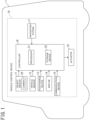
- the vehicle control device 10 includes object sensors 11, vehicle sensors 12, a positioning device 13, a map database 14, a communication device 15, a navigation system 17, a controller 18, and actuators 19.
- the map database is referred to as "map DB" in the drawings.
- the object sensors 11 include a plurality of sensors of different types that are configured to detect objects around the own vehicle 1.
- the object sensors 11 include a camera 20 mounted on the own vehicle 1.
- the camera 20 captures an image within a predetermined range of the angle of view (imaging range) in front of the own vehicle 1 and outputs the captured image to the controller 18.
- imaging is also described as “image capturing” and the terms are used, assuming that the terms represent the same meaning herein.
- the object sensors 11 may include a range sensor, such as a laser radar, a millimeter-wave radar, and a light detection and ranging or laser imaging detection and ranging (LIDAR).
- a range sensor such as a laser radar, a millimeter-wave radar, and a light detection and ranging or laser imaging detection and ranging (LIDAR).
- the vehicle sensors 12 are mounted on the own vehicle 1 and detect various information (vehicle signals) that is acquired from the own vehicle 1.
- the vehicle sensors 12 include, for example, a vehicle speed sensor configured to detect traveling speed (vehicle speed) of the own vehicle 1, wheel speed sensors configured to detect rotational speed of respective tires that the own vehicle 1 has, a triaxial acceleration sensor (G sensor) configured to detect acceleration (including deceleration) in three axial directions of the own vehicle 1, a steering angle sensor configured to detect a steering angle (including a turning angle), a gyro sensor configured to detect angular velocity generated in the own vehicle 1, a yaw rate sensor configured to detect a yaw rate, an accelerator sensor configured to detect an accelerator opening of the own vehicle, and a brake sensor configured to detect the amount of brake operation by the driver.
- a vehicle speed sensor configured to detect traveling speed (vehicle speed) of the own vehicle 1
- wheel speed sensors configured to detect rotational speed of respective tires that the own vehicle 1 has
- the positioning device 13 includes a global navigation satellite system (GNSS) receiver and receives radio waves from a plurality of navigation satellites and thereby measures a current position of the own vehicle 1.
- GNSS global navigation satellite system
- the GNSS receiver may be, for example, a global positioning system (GPS) receiver.
- GPS global positioning system
- the positioning device 13 may be, for example, an inertial navigation device.
- the map database 14 may store high-precision map data (hereinafter, simply referred to as "high-precision map”) that are suitable as map information for self-driving.
- the high-precision map is map data of higher precision than map data for navigation (hereinafter, simply referred to as “navigation map”) and includes lane-by-lane information, which is more detailed than road-by-road information.
- lane information included in the high-precision map data is referred to as "lane information”.
- the high-precision map includes, as lane information, information of lane nodes that indicate reference points on a lane reference line (for example, a central line in a lane) and information of lane links that indicate forms of lane sections between lane nodes.
- Information of each lane node includes an identification number and position coordinates of the lane node, the number of connected lane links, and identification numbers of connected lane links.
- Information of each lane link includes an identification number of the lane link, a type of the lane, width of the lane, types of lane boundary lines, a shape of the lane, a gradient of the lane, a shape of a lane marking, and a shape of a lane reference line.
- the high-precision map further includes types and position coordinates of ground objects, such as a stop line, a road sign, a building, a utility pole, a curb, and a crosswalk, that exist on a lane or in the vicinity of the lane and information of the ground objects, such as identification numbers of lane nodes and identification numbers of lane links that correspond to the position coordinates of the ground objects.
- ground objects such as a stop line, a road sign, a building, a utility pole, a curb, and a crosswalk
- the high-precision map further includes information of a traffic light that exists on a lane or in the vicinity of the lane.
- Information of traffic lights included in the high-precision map data is sometimes referred to as "traffic light information”.
- the traffic light information includes information of an installation position of each traffic light and identification information of a stop line corresponding to each traffic light.
- the traffic light information specifies a lane on which traffic is controlled by the traffic light, via the identification information of the stop line corresponding to the traffic light.
- the traffic light information may include, for example, information of a lane node of an intersection at which the traffic light is installed or information of a crosswalk at which the traffic light is installed.
- the traffic light information specifies a lane on which traffic is controlled by the traffic light, via such information.
- a "lane on which traffic is controlled by a traffic light” is a lane on which traveling beyond a stop line installed corresponding to the traffic light is allowed or prohibited depending on indication of the traffic light or a lane on which entering an intersection or a crosswalk at which the traffic light is installed is allowed or prohibited depending on indication of the traffic light.
- the information of the installation position of a traffic light includes at least two-dimensional coordinates in the map coordinate system (or a global coordinate system) of a position at which the traffic light is installed.
- the information of the installation position of a traffic light may include, in addition to the two-dimensional coordinates of the position at which the traffic light is installed, height information of the traffic light.
- the installation height of traffic lights is prescribed to a value within a predetermined range by a law, the height of a traffic light does not necessarily have to be included in the high-precision map data.
- the communication device 15 performs wireless communication with a communication device external to the own vehicle 1.
- a communication method used by the communication device 15 may be, for example, wireless communication through a public mobile telephone network, vehicle-to-vehicle communication, road-to-vehicle communication, or satellite communication.
- the navigation system 17 recognizes a current position of the own vehicle 1, using the positioning device 13 and acquires map information at the current position from the map database 14.
- the navigation system 17 sets a travel route to a destination that a passenger inputs and performs route guidance for the passenger in accordance with the travel route.
- the navigation system 17 also outputs information on the set travel route to the controller 18.
- the controller 18 causes the own vehicle 1 to self-drive in such a way that the own vehicle 1 travels along the travel route set by the navigation system 17.
- the controller 18 is an electronic control unit (ECU) that performs vehicle control of the own vehicle 1.
- the controller 18 includes a processor 21 and peripheral components, such as a storage device 22.
- the processor 21 may be, for example, a central processing unit (CPU) or a micro-processing unit (MPU).
- the storage device 22 may include a semiconductor storage device, a magnetic storage device, an optical storage device, and the like.
- the storage device 22 may include registers, a cache memory, a memory, such as a read only memory (ROM) or a random access memory (RAM), that is used as a main storage device, or the like.
- ROM read only memory
- RAM random access memory
- Functions of the controller 18, which will be described below, may be achieved by, for example, the processor 21 executing computer programs stored in the storage device 22.
- controller 18 may be formed using dedicated hardware for performing information processing that will be described below.
- the controller 18 may include a functional logic circuit that is implemented in a general-purpose semiconductor integrated circuit.
- the controller 18 may include a programmable logic device (PLD), such as a field-programmable gate array (FPGA), and the like.
- PLD programmable logic device
- FPGA field-programmable gate array
- the actuators 19 operate the steering wheel, the accelerator opening, and a braking device of the own vehicle 1 according to a control signal from the controller 18 and thereby generates vehicle behavior of the own vehicle 1.
- the actuators 19 include a steering actuator, an accelerator opening actuator, and a brake control actuator.
- the steering actuator controls steering direction and the amount of steering in the steering of the own vehicle 1.
- the accelerator opening actuator controls the accelerator opening of the own vehicle 1.
- the brake control actuator controls braking action of the braking device of the own vehicle 1.
- the controller 18 recognizes a traffic light that controls traffic on a lane on which the own vehicle 1 travels, from a captured image captured by the camera 20.
- the controller 18 causes the own vehicle 1 to travel or stop in accordance with indication of the recognized traffic light.
- the controller 18 calculates a range of the angle of view (image capturing range) of the camera 20, based on optical information of the camera 20 (such as information of the angle of view of the camera 20) and installation information of the camera 20 (such as a mounting position of the camera on the own vehicle 1 and an orientation of the optical system of the camera).
- the optical information and the installation information of the camera 20 are set and stored in the storage device 22 in advance. Note that, when the installation information of the camera 20 (the mounting position of the camera and the orientation of the optical system with respect to the own vehicle 1) does not change, that is, when an installation state of the camera with respect to the own vehicle 1 is fixed, the installation information of the camera 20 is not necessarily needed because the range of the angle of view of the camera 20 with respect to the own vehicle is fixed.
- the controller 18 calculates an imaging-enabled area in which an image of a traffic light can be captured on the lane by the camera 20 in a case where there exists no preceding vehicle, based on the range of the angle of view of the camera 20 and the map information.
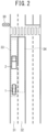
- FIG. 2 is now referred to.
- a case is now assumed where a traffic light 30 exists in front of the own vehicle 1.
- the traffic light 30 is a traffic light that controls traffic on a plurality of lanes 31 and 32. Traveling directions of the lanes 31 and 32 are the same, and the lane 31 is the travel lane of the own vehicle 1 and the lane 32 is an adjacent lane of the lane 31.
- the controller 18 calculates an imaging-enabled area 33 in which an image of the traffic light 30 can be captured on the lane 31 by the camera 20 in a case where there exists no other vehicle on the road, based on traffic light information of the traffic light 30, lane information of the lane 31, and the range of the angle of view of the camera 20.
- the imaging-enabled area 33 is an area in which an image of the traffic light 30 can be expected to be captured on the lane 31 by the camera 20 unless the range of the angle of view of the camera 20 is shielded by a preceding vehicle 2. Conversely, an area on the lane 31 outside the imaging-enabled area 33 is an area in which an image of the traffic light 30 cannot be captured even when the range of the angle of view of the camera 20 is not shielded.
- the controller 18 also calculates an imaging-enabled area 34 with respect to the lane 32. That is, the controller 18 calculates an imaging-enabled area 34 in which an image of the traffic light 30 can be captured on the lane 32 by the camera 20 in a case where there exists no other vehicle on the road, based on the traffic light information of the traffic light 30, lane information of the lane 32, and the range of the angle of view of the camera 20.
- the controller 18 determines whether or not the own vehicle 1 is positioned in the imaging-enabled area 33 or 34.
- the controller 18 controls the own vehicle 1 in such a way that the traffic light 30 is not shielded from the range of the angle of view of the camera 20 by the preceding vehicle 2.
- the controller 18 calculates an inter-vehicle distance at which the traffic light 30 is not shielded by the preceding vehicle 2 and, by decelerating the own vehicle 1 according to the inter-vehicle distance, increases an inter-vehicle distance between the preceding vehicle 2 and the own vehicle 1.
- the controller 18 may steer the own vehicle in such a way as to increase lateral positional deviation between the own vehicle 1 and the preceding vehicle 2 in a direction in which the traffic light 30 is deviated away from the center of the lane 31.
- the controller 18 controls speed of the own vehicle 1 in such a way as to maintain the inter-vehicle distance between the preceding vehicle 2 and the own vehicle 1 at an inter-vehicle distance at which the traffic light 30 is not shielded by the preceding vehicle 2.
- shielding avoidance control The travel control of the own vehicle 1 to avoid the traffic light 30 from being shielded from the range of the angle of view of the camera 20 by the preceding vehicle 2 as described above is hereinafter referred to as "shielding avoidance control".
- This configuration enables the shielding avoidance control to be prevented from being unnecessarily executed in an area in which an image of the traffic light 30 cannot be captured originally. As a result, it is possible to suppress a sense of discomfort from being given to the passenger of the own vehicle 1 by unnecessary execution of the shielding avoidance control.
- the controller 18 controls the inter-vehicle distance between the preceding vehicle 2 and the own vehicle 1 in such a way that the inter-vehicle distance coincides with a determined target value regardless of whether or not the traffic light 30 is shielded from the range of the angle of view of the camera 20 by the preceding vehicle 2.
- the controller 18 may determine a target value of the inter-vehicle distance to a preceding vehicle according to speed of the own vehicle 1.
- controller 18 may control the lateral position of the own vehicle 1 in such a way that the lateral position of the own vehicle 1 in the lane 31, which is the travel lane of the own vehicle 1, coincides with a predetermined initial value (for example, the lane center).
- the controller 18 includes an object detection unit 40, an own-vehicle position estimation unit 41, a map acquisition unit 42, a detection integration unit 43, an object tracking unit 44, a preceding vehicle detection unit 45, a position-in-map calculation unit 46, a traffic light recognition unit 47, a shielding avoidance control unit 48, an own-vehicle route generation unit 49, and a vehicle control unit 50.
- the object detection unit 40 detects a position, an attitude, a size, a speed, and the like of an object, such as a vehicle, a motorcycle, a pedestrian, and an obstacle, around the own vehicle 1, based on detection signals from the object sensors 11.
- the object detection unit 40 outputs a detection result representing a two-dimensional position, an attitude, a size, a speed, and the like of an object in, for example, a zenith view (also referred to as a plan view), which is a view of the own vehicle 1 viewed from the air.
- the own-vehicle position estimation unit 41 measures an absolute position, that is, a position of the own vehicle 1 with respect to a predetermined reference point, an attitude, and a speed of the own vehicle 1, based on a measurement result by the positioning device 13 and odometry using detection results from the vehicle sensors 12.
- the map acquisition unit 42 acquires map information of a road on which the own vehicle 1 travels from the map database 14.
- the map acquisition unit 42 may acquire map information from an external map data server through the communication device 15.
- the map information acquired by the map acquisition unit 42 includes traffic light information of a traffic light existing in front of the own vehicle 1 on the path of the own vehicle 1, lane information of a lane on which traffic is controlled by the traffic light, and information of ground objects existing on the lane or in the vicinity thereof.
- the detection integration unit 43 integrates a plurality of detection results that the object detection unit 40 has respectively acquired from a plurality of object detection sensors and outputs a single set of a two-dimensional position, an attitude, a size, a speed, and the like with respect to each object. Specifically, the detection integration unit 43 calculates, from behavior of each object acquired from the respective ones of the object detection sensors, the most reasonable behavior of the object that minimizes error in consideration of error characteristics and the like of the respective object detection sensors.
- the detection integration unit 43 comprehensively evaluates detection results acquired from a plurality of types of sensors by using a known sensor fusion technology and thereby acquires a more accurate detection result.
- the object tracking unit 44 tracks an object detected by the object detection unit 40. Specifically, the object tracking unit 44 performs verification of identity (association) among objects detected at different time points from behaviors of an object output at different time points, based on detection results integrated by the detection integration unit 43 and, based on the association, predicts behavior of the object, such as speed of the object.
- identity association
- the object tracking unit 44 performs verification of identity (association) among objects detected at different time points from behaviors of an object output at different time points, based on detection results integrated by the detection integration unit 43 and, based on the association, predicts behavior of the object, such as speed of the object.
- the preceding vehicle detection unit 45 detects a preceding vehicle in front of the own vehicle 1 out of objects that exist around the own vehicle 1 and that are detected by the detection integration unit 43 and the object tracking unit 44 and outputs a detection result to the shielding avoidance control unit 48.
- the position-in-map calculation unit 46 estimates a position and an attitude of the own vehicle 1 on the map from the absolute position of the own vehicle 1, which is acquired by the own-vehicle position estimation unit 41, and the map information, which is acquired by the map acquisition unit 42.
- the position-in-map calculation unit 46 identifies a road on which the own vehicle 1 is traveling and also a lane on which the own vehicle 1 travels within the identified road.
- the position-in-map calculation unit 46 outputs the position and attitude of the own vehicle 1 on the map and information of the lane on which the own vehicle 1 travels to the shielding avoidance control unit 48.
- the traffic light recognition unit 47 analyzes a captured image captured by the camera 20 and recognizes a traffic light and a lighting color thereof.
- the traffic light recognition unit 47 outputs a recognition result of a traffic light to the shielding avoidance control unit 48.
- the shielding avoidance control unit 48 executes the shielding avoidance control to avoid a traffic light in front of the own vehicle 1 from being shielded from the range of the angle of view of the camera 20 by a preceding vehicle, based on the map information acquired by the map acquisition unit 42, a detection result detected by the preceding vehicle detection unit 45, a position of the own vehicle 1 identified by the position-in-map calculation unit 46, and a recognition result by the traffic light recognition unit 47.
- the shielding avoidance control unit 48 includes an imaging-enabled area calculation unit 51, an image capturing possibility determination unit 52, and a control amount setting unit 53.
- the imaging-enabled area calculation unit 51 calculates an imaging-enabled area in which an image of a traffic light in front of the own vehicle 1 can be captured from a position on the lane controlled by the traffic light, using the camera 20, based on the optical information and the installation information of the camera 20 and the map information.
- FIG. 4 is now referred to.
- traffic lights 30a and 30b exist in front of the own vehicle 1.
- the traffic lights 30a and 30b are traffic lights that control traffic on a plurality of lanes 31 and 32.
- the lanes 31 and 32 are lanes the traveling directions of which are the same and that are adjacent to each other.
- the imaging-enabled area calculation unit 51 calculates an imaging-enabled area with respect to each of the plurality of lanes 31 and 32. First, calculation of an imaging-enabled area on the lane 31 will be described.
- the imaging-enabled area calculation unit 51 calculates an imaging-enabled area 33a in which an image of the traffic light 30a among the plurality of traffic lights 30a and 30b can be captured.
- the imaging-enabled area calculation unit 51 calculates the imaging-enabled area 33a, based on information of an installation position and height of the traffic light 30a, a road structure and a gradient of the lane 31, and the optical information and the installation information of the camera 20.
- the imaging-enabled area calculation unit 51 may calculate the imaging-enabled area 33a by searching for a point on the lane 31 at which an image of the traffic light 30a can be captured.
- the imaging-enabled area calculation unit 51 may determine that the camera 20 can capture an image of the traffic light 30a when the traffic light 30a is positioned within both a vertical range of the angle of view and a horizontal range of the angle of view of the camera 20 and determine that the camera 20 cannot capture an image of the traffic light 30a when the traffic light 30a is positioned out of either the vertical range of the angle of view or the horizontal range of the angle of view.
- FIG. 5A is now referred to.
- the imaging-enabled area calculation unit 51 determines that the traffic light 30a is positioned within the vertical range of the angle of view of the camera 20 when, for example, the formulae (1) and (2) below are satisfied.
- xb is horizontal distance from the own vehicle 1 to the traffic light 30a
- x0 is longitudinal distance from the front edge of the own vehicle 1 to the mounting position of the camera
- yc is height of the mounting position of the camera
- ys1 is height of the top edge of the traffic light 30a
- ys2 is height of the lower edge of the traffic light 30a.
- ⁇ 1 is an elevation angle of an upper limit 35 of the range of the angle of view of the camera 20
- ⁇ 2 is an elevation angle of a lower limit 36 of the range of the angle of view of the camera 20.
- a value that can be assumed to be a height of a general traffic light, based on an installation standard stipulated by an administrative organ or the like may be used as the height of the traffic light 30a.
- ys1 and ys2 may be assumed to be 5.7 m and 4.7 m, respectively.
- the longitudinal distance (x0) from the front edge of the own vehicle 1 to the mounting position of the camera 20, the height (yc) of the mounting position of the camera 20, the elevation angle ( ⁇ 1) of the upper limit 35 of the range of the angle of view of the camera 20, and the elevation angle ( ⁇ 2) of the lower limit 36 of the range of the angle of view of the camera 20 do not change.
- the vertical range of the angle of view of the camera 20 with respect to the own vehicle 1 does not change, storing the vertical range of the angle of view of the camera 20 with respect to the own vehicle 1 in advance and detecting only the horizontal distance (xb) from the own vehicle 1 to the traffic light 30a enable the imaging-enabled area calculation unit 51 to determine that the traffic light 30a is positioned within the vertical range of the angle of view of the camera 20.
- the imaging-enabled area calculation unit 51 may detect the longitudinal distance (x0) from the front edge of the own vehicle 1 to the mounting position of the camera 20, the height (yc) of the mounting position of the camera 20, the elevation angle ( ⁇ 1) of the upper limit 35 of the range of the angle of view of the camera 20, and the elevation angle ( ⁇ 2) of the lower limit 36 of the range of the angle of view of the camera 20 and, using the above-described formulae (1) and (2), determine whether or not the traffic light 30a is positioned within the vertical range of the angle of view of the camera 20.
- FIG. 5B is now referred to.
- the imaging-enabled area calculation unit 51 determines whether or not the traffic light 30a is positioned within the horizontal range of the angle of view of the camera 20, based on deviation in the lateral direction of the traffic light 30a with respect to an optical center 20c of the camera 20, horizontal distance (xb+x0) from the camera 20 to the traffic light 30a, and a horizontal angle of view ⁇ h of the camera 20.
- the own vehicle 1 is positioned at the center of the lane 31.
- installation position information of the traffic light 30a included in the map information is two-dimensional coordinates of a pillar 37 of the traffic light 30a
- the coordinates of the pillar 37 may be used as the coordinates of the traffic light 30a.
- FIG. 4 is now referred to.
- a point nearest to a traffic light within an imaging-enabled area is referred to as “near end”
- a point furthest from the traffic light within the imaging-enabled area is referred to as "far end”.
- the near end of the imaging-enabled area 33a is denoted by a reference sign 33c
- the far end of the imaging-enabled area 33a is denoted by a reference sign 33d.
- An upper limit of distance between the far end 33d of the imaging-enabled area 33a and the traffic light 30a may be determined with performance of the optical system of the camera 20 considered.
- the far end 33d may be set according to the minimum number of pixels required to recognize the traffic light 30a on a captured image.
- the far end 33d may be set in such a way that distance from the traffic light 30a to the far end 33d is equal to or less than a threshold value.
- the imaging-enabled area calculation unit 51 also calculates, with respect to the traffic light 30b, an imaging-enabled area 33b in which an image of the traffic light 30b can be captured on the lane 31, in a similar manner.
- the imaging-enabled area calculation unit 51 calculates the imaging-enabled areas 33a and 33b in which images of the traffic lights 30a and 30b can be captured on the lane 31 with respect to all the traffic lights 30a and 30b controlling traffic on the lane 31, respectively.
- the imaging-enabled area calculation unit 51 calculates a union area of the imaging-enabled areas 33a and 33b (that is, an area in which any point therein is included at least either of the imaging-enabled areas 33a and 33b) as an imaging-enabled area in which an image of at least one of the traffic lights 30a and 30b, which control traffic on the lane 31, can be captured on the lane 31.
- the imaging-enabled area calculation unit 51 also calculates an overlapping area 33e of the imaging-enabled areas 33a and 33b.
- FIG. 6 is now referred to.
- the imaging-enabled area calculation unit 51 calculates an imaging-enabled area on the lane 32 that is adjacent to the lane 31.
- the imaging-enabled area calculation unit 51 calculates an imaging-enabled area 34a in which an image of the traffic light 30a can be captured on the lane 32 and an imaging-enabled area 34b in which an image of the traffic light 30b can be captured on the lane 32.
- the imaging-enabled area calculation unit 51 calculates a union area of the imaging-enabled areas 34a and 34b as an imaging-enabled area in which an image of at least one of the traffic lights 30a and 30b, which control traffic on the lane 32, can be captured on the lane 32.
- the imaging-enabled area calculation unit 51 also calculates an overlapping area 34c of the imaging-enabled areas 34a and 34b.
- FIG. 3 is now referred to.
- the image capturing possibility determination unit 52 determines whether or not the own vehicle 1 is positioned in the imaging-enabled areas calculated by the imaging-enabled area calculation unit 51 (for example, whether or not the own vehicle 1 is traveling in the imaging-enabled areas).
- the image capturing possibility determination unit 52 determines whether or not the own vehicle 1 is positioned in either the union area of the imaging-enabled areas 33a and 33b or the union area of the imaging-enabled areas 34a and 34b. That is, the image capturing possibility determination unit 52 determines whether or not the own vehicle 1 is positioned in any of the imaging-enabled areas 33a, 33b, 34a, and 34b.
- the control amount setting unit 53 sets a target control amount in the travel control of the own vehicle 1 for the shielding avoidance control depending on a recognition state of traffic lights recognized by the traffic light recognition unit 47 and a detection result of a preceding vehicle detected by the preceding vehicle detection unit 45.
- the control amount setting unit 53 sets, as a target control amount, for example, a target inter-vehicle distance between the own vehicle 1 and a preceding vehicle or a target lateral position of the own vehicle 1 in the travel lane.
- FIG. 7 is now referred to. A case is now assumed where the image capturing possibility determination unit 52 has determined that the own vehicle 1 is positioned in an imaging-enabled area and the preceding vehicle detection unit 45 has detected a preceding vehicle 2.
- the control amount setting unit 53 determines whether or not the traffic light recognition unit 47 recognizes the traffic light 30a or 30b. When the control amount setting unit 53 determines that the traffic light recognition unit 47 recognizes the traffic light 30a or 30b, the control amount setting unit 53 determines that the current inter-vehicle distance is an inter-vehicle distance at which at least one of the traffic lights 30a and 30b is not shielded from the range of the angle of view of the camera 20 by the preceding vehicle 2 and sets the current inter-vehicle distance as a target inter-vehicle distance.
- control amount setting unit 53 determines that the traffic light recognition unit 47 recognizes neither the traffic light 30a nor 30b, the control amount setting unit 53 sets a target control amount in such a way that at least one of the traffic lights 30a and 30b is prevented from being shielded from the range of the angle of view of the camera 20 by the preceding vehicle 2.
- the control amount setting unit 53 calculates an inter-vehicle distance at which the traffic light 30a is not shielded by the preceding vehicle 2 and sets the calculated inter-vehicle distance as a target inter-vehicle distance.
- the control amount setting unit 53 determines that the inter-vehicle distance between the preceding vehicle 2 and the own vehicle 1 is small and the traffic light 30a is shielded by the preceding vehicle 2, and increases the inter-vehicle distance between the preceding vehicle 2 and the own vehicle 1 to an inter-vehicle distance at which the traffic light 30a is not shielded by the preceding vehicle 2.
- FIG. 8 is now referred to.
- the control amount setting unit 53 calculates an inter-vehicle distance x1 at which the traffic light 30a is not shielded by the preceding vehicle 2, using the formula (3) below.
- x 1 xb + x 0 ⁇ yt ⁇ yc / ys ⁇ yc ⁇ x 0
- yt denotes height of the preceding vehicle 2
- ys denotes height of the traffic light 30a.
- the control amount setting unit 53 calculates an inter-vehicle distance at which the traffic light 30b is not shielded by the preceding vehicle 2, and sets the calculated inter-vehicle distance as a target inter-vehicle distance.
- the control amount setting unit 53 calculates either an inter-vehicle distance at which the traffic light 30a is not shielded by the preceding vehicle 2 or an inter-vehicle distance at which the traffic light 30b is not shielded by the preceding vehicle 2, and sets the calculated inter-vehicle distance as a target inter-vehicle distance.
- the control amount setting unit 53 may calculate both an inter-vehicle distance at which the traffic light 30a is not shielded by the preceding vehicle 2 and an inter-vehicle distance at which the traffic light 30b is not shielded by the preceding vehicle 2, and set an inter-vehicle distance smaller than the other among the calculated inter-vehicle distances as a target inter-vehicle distance or set an inter-vehicle distance larger than the other thereamong as a target inter-vehicle distance.
- the control amount setting unit 53 may set a target lateral position of the own vehicle 1 in the travel lane 31. That is, the control amount setting unit 53 may set a lateral position in the travel lane 31 that causes lateral positional deviation between the own vehicle 1 and the preceding vehicle 2 to increase, as a target lateral position.
- control amount setting unit 53 determines whether or not the traffic light 30a is deviated away from the center of the lane 31.
- the control amount setting unit 53 sets a target lateral position in such a way that lateral position deviation ⁇ between the own vehicle 1 and the preceding vehicle 2 increases in the direction in which the traffic light 30a is deviated away from the center of the lane 31.
- the control amount setting unit 53 sets a target lateral position in such a way that the deviation ⁇ increases in the leftward direction.
- control amount setting unit 53 determines whether or not the traffic light 30b is deviated away from the center of the lane 31.
- the control amount setting unit 53 sets a target lateral position in such a way that the lateral positional deviation ⁇ between the own vehicle 1 and the preceding vehicle 2 increases in the direction in which the traffic light 30b is deviated away from the center of the lane 31.
- the control amount setting unit 53 sets a target lateral position in such a way that the deviation ⁇ increases in the rightward direction.
- the control amount setting unit 53 may set a target lateral position in such a way that the deviation ⁇ increases in the leftward direction or may set a target lateral position in such a way that the deviation ⁇ increases in the rightward direction.
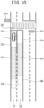
- FIG. 10 is now referred to. A case is now assumed where the image capturing possibility determination unit 52 has determined that the own vehicle 1 is positioned in an imaging-enabled area and the preceding vehicle detection unit 45 has not detected a preceding vehicle 2.
- the traffic light recognition unit 47 sometimes cannot recognize the traffic light 30a or 30b depending on a photographing condition, such as the direction of sunlight, and a device state of the camera 20.
- the control amount setting unit 53 determines whether or not the traffic light recognition unit 47 recognizes the traffic light 30a or 30b.
- the own vehicle 1 cannot travel further forward than a stop line 38 corresponding to the traffic light 30a or 30b because the lighting color of the traffic light 30a or 30b is unclear.
- the camera 20 cannot capture an image of the traffic light 30a or 30b even when the photographing condition and the device state get better.
- control amount setting unit 53 sets a position that is further from the traffic light 30a than the other among the stop line 38 and the near end 33c of the imaging-enabled area 33a as a target stop position.
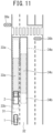
- FIG. 11 is now referred to.
- the control amount setting unit 53 suppresses the above-described shielding avoidance control.
- control amount setting unit 53 determines that the traffic light recognition unit 47 recognizes neither the traffic light 30a nor the traffic light 30b, the control amount setting unit 53 does not change a determined target inter-vehicle distance and target lateral position in autonomous travel control or constant speed travel control, regardless of whether or not the traffic light 30a or 30b is shielded from the range of the angle of view of the camera 20 by a preceding vehicle 2.
- a target control amount for the shielding avoidance control can similarly be set using the imaging-enabled areas 34a and 34b and the overlapping area 34c with respect to a case where the own vehicle 1 travels on the lane 32.
- FIG. 3 is now referred to.
- the own-vehicle route generation unit 49 generates a target travel track and a speed profile of the own vehicle 1 in such a way that the own vehicle 1 travels along a travel lane of the own vehicle 1 without colliding with another vehicle in accordance with traffic rules, based on a result of detection, by the detection integration unit 43 and the object tracking unit 44, of an object around the own vehicle 1 and vehicle signals from the vehicle sensors 12.
- the own-vehicle route generation unit 49 generates the speed profile in such a way that the inter-vehicle distance between the own vehicle 1 and a preceding vehicle coincides with a target inter-vehicle distance set by the shielding avoidance control unit 48.
- the own-vehicle route generation unit 49 generates a target travel track that causes the own vehicle 1 to change the lateral position in a lane of the own vehicle 1 to a target lateral position set by the shielding avoidance control unit 48.
- the own-vehicle route generation unit 49 generates a target travel track and a speed profile that causes the own vehicle to stop at a target stop position set by the shielding avoidance control unit 48.
- the vehicle control unit 50 drives the actuators 19 in such a way that the own vehicle 1 travels on a target travel track at speed according to a speed profile that the own-vehicle route generation unit 49 has generated.
- the vehicle control unit 50 decelerates the own vehicle 1 by controlling the brake control actuator.
- the vehicle control unit 50 maintains the inter-vehicle distance to the preceding vehicle by controlling the accelerator opening actuator and the brake control actuator.
- the vehicle control unit 50 steers the own vehicle 1 by controlling the steering actuator and causes the own vehicle 1 to change the lateral position thereof to the set target lateral position.
- the vehicle control unit 50 causes the own vehicle to stop at the set target stop position.
- the control amount setting unit 53 determines whether or not the traffic light recognition unit 47 recognizes a traffic light.
- the control amount setting unit 53 determines that the traffic light recognition unit 47 does not recognize a traffic light even when the inter-vehicle distance between the own vehicle 1 and the preceding vehicle coincides with the target inter-vehicle distance, it is considered that the traffic light recognition unit 47 cannot recognize a traffic light because of a factor other than a preceding vehicle (for example, a photographing condition or a device state of the camera 20).
- the control amount setting unit 53 sets a position that is further from the traffic light 30a than the other among the stop line 38 and the near end 33c of the imaging-enabled area 33a as a target stop position.
- the traffic light recognition unit 47 cannot recognize the traffic light 30a or 30b even when, as a result of increase in the lateral positional deviation ⁇ between the own vehicle 1 and the preceding vehicle 2, the lateral position of the own vehicle 1 reaches a maximum allowable lateral position.
- step S1 the controller 18 sets a target inter-vehicle distance and a target lateral position in autonomous travel control and constant speed travel control.
- the controller 18 may set a target inter-vehicle distance according to speed of the own vehicle 1.
- the controller 18 may set the center of a travel lane of the own vehicle 1 as a target lateral position.
- step S2 the map acquisition unit 42 acquires map information of a road on which the own vehicle 1 travels.
- step S3 the traffic light recognition unit 47 acquires a captured image captured by the camera 20.
- the traffic light recognition unit 47 analyzes the captured image captured by the camera 20 and recognizes a traffic light and a lighting color thereof.
- step S4 the own-vehicle position estimation unit 41 estimates a current position of the own vehicle 1.
- step S5 the preceding vehicle detection unit 45 detects a preceding vehicle in front of the own vehicle 1.
- step S6 the imaging-enabled area calculation unit 51 calculates an imaging-enabled area in which an image of the traffic light can be captured on the lane by the camera 20.
- step S7 the image capturing possibility determination unit 52 determines whether or not the own vehicle 1 is positioned in the imaging-enabled area.
- step S7: N the process proceeds to step S8.
- step S8 the own-vehicle route generation unit 49 and the vehicle control unit 50 control traveling of the own vehicle according to the target inter-vehicle distance and the target lateral position set in step S1.
- This processing causes shielding avoidance control performed by the shielding avoidance control unit 48 to be suppressed. Subsequently, the process is terminated.
- step S7 determines that the own vehicle 1 is positioned in the imaging-enabled area in step S7 (step S7: Y)
- the process proceeds to step S9.
- step S9 the control amount setting unit 53 determines whether or not the traffic light recognition unit 47 recognizes the traffic light.
- step S9: Y the process proceeds to step S10.
- step S9: N the process proceeds to step S12.
- step S10 the control amount setting unit 53 determines whether or not the preceding vehicle detection unit 45 recognizes a preceding vehicle 2.
- step S11 the control amount setting unit 53 determines that the current inter-vehicle distance is an inter-vehicle distance at which the traffic light is not shielded from the range of the angle of view of the camera 20 by the preceding vehicle and sets the current inter-vehicle distance as a target inter-vehicle distance in such a way as to maintain the current inter-vehicle distance. Subsequently, the process proceeds to step S8.
- step S8 the own-vehicle route generation unit 49 and the vehicle control unit 50 control speed of the own vehicle 1 in such a way as to maintain the current inter-vehicle distance set as the target inter-vehicle distance. Subsequently, the process is terminated.
- step S10: N the control amount setting unit 53 determines that the preceding vehicle detection unit 45 does not recognize the preceding vehicle 2 in step S10 (step S10: N). the process proceeds to step S8.
- step S8 the own-vehicle route generation unit 49 and the vehicle control unit 50 control traveling of the own vehicle according to the target inter-vehicle distance and the target lateral position set in step S1. Subsequently, the process is terminated.
- step S12 the control amount setting unit 53 determines whether or not the preceding vehicle detection unit 45 recognizes a preceding vehicle 2.
- the control amount setting unit 53 determines that the preceding vehicle detection unit 45 recognizes the preceding vehicle 2 (step S12: Y)
- the process proceeds to step S13.
- step S13 the control amount setting unit 53 calculates an inter-vehicle distance at which the traffic light is not shielded by the preceding vehicle and sets the calculated inter-vehicle distance as a target inter-vehicle distance. This processing causes the target inter-vehicle distance to increase.
- control amount setting unit 53 sets a target lateral position that causes lateral positional deviation between the own vehicle and the preceding vehicle to increase. Subsequently, the process proceeds to step S8.
- step S8 the own-vehicle route generation unit 49 and the vehicle control unit 50 cause the own vehicle 1 to decelerate in such a way that the inter-vehicle distance between the own vehicle 1 and the preceding vehicle coincides with the target inter-vehicle distance set by the control amount setting unit 53.
- the own-vehicle route generation unit 49 and the vehicle control unit 50 steer the own vehicle 1 in such a way that the lateral position of the own vehicle 1 is changed to the target lateral position. Subsequently, the process is terminated.
- step S12 determines that the preceding vehicle detection unit 45 does not detect the preceding vehicle 2 in step S12 (step S12: N)
- step S14 determines that the preceding vehicle detection unit 45 does not detect the preceding vehicle 2 in step S12 (step S12: N)
- step S14 the control amount setting unit 53 sets a position that is further from the traffic light than the other among a near end of an imaging-enabled area and a stop line as a target stop position. Subsequently, the process proceeds to step S8.
- step S8 the own-vehicle route generation unit 49 and the vehicle control unit 50 cause the own vehicle 1 to stop at the target stop position. Subsequently, the process is terminated.
- the control amount setting unit 53, the own-vehicle route generation unit 49, and the vehicle control unit 50 control the own vehicle 1 in such a way that the traffic light is not shielded from the range of the angle of view of the camera 20 by a preceding vehicle of the own vehicle 1.
- This configuration enables the shielding avoidance control to be prevented from being unnecessarily executed in an area in which, even when no other vehicle exists on the lane, an image of the traffic light cannot be captured by the camera 20 originally. As a result, it is possible to suppress a sense of discomfort from being unnecessarily given to a passenger of the own vehicle 1 by the shielding avoidance control.
- the control amount setting unit 53 determines whether or not a traffic light is recognized from a captured image captured by the camera 20, and, when the traffic light is recognized from the captured image, the own-vehicle route generation unit 49 and the vehicle control unit 50 control the own vehicle in such a way as to maintain the inter-vehicle distance between a preceding vehicle and the own vehicle at an inter-vehicle distance at which the traffic light is not shielded by the preceding vehicle.
- This configuration enables the own vehicle 1 to be controlled in such a way that the traffic light is not shielded by the preceding vehicle.
- the control amount setting unit 53 determines whether or not a traffic light is recognized from a captured image captured by the camera 20 and determines whether or not a preceding vehicle exists .
- the control amount setting unit 53, the own-vehicle route generation unit 49, and the vehicle control unit 50 control the own vehicle 1 in such a way as to increase inter-vehicle distance between the preceding vehicle and the own vehicle 1.
- This configuration enables the own vehicle 1 to be controlled in such a way that the traffic light is not shielded by the preceding vehicle.
- the control amount setting unit 53 calculates an inter-vehicle distance at which a traffic light is not shielded by a preceding vehicle.
- the own-vehicle route generation unit 49 and the vehicle control unit 50 by decelerating the own vehicle 1 according to the inter-vehicle distance, increase the inter-vehicle distance between the preceding vehicle and the own vehicle.
- This configuration enables speed of the own vehicle 1 to be controlled in such a way that the traffic light is not shielded by the preceding vehicle.
- the control amount setting unit 53, the own-vehicle route generation unit 49, and the vehicle control unit 50 steer the own vehicle 1 in such a way as to increase lateral positional deviation between the own vehicle 1 and a preceding vehicle in a direction in which the traffic light is deviated away from the center of the lane.
- This configuration enables the own vehicle 1 to be steered in such a way that the traffic light is not shielded by the preceding vehicle.
- the control amount setting unit 53, the own-vehicle route generation unit 49, and the vehicle control unit 50 cause the own vehicle 1 to stop at a position that is further from the traffic light than the other among a stop line corresponding to the traffic light and a closest point to the traffic light in an imaging-enabled area.
- the control amount setting unit 53 determines whether or not a traffic light is recognized from a captured image captured by the camera 20 and determines whether or not a preceding vehicle exists .
- the control amount setting unit 53, the own-vehicle route generation unit 49, and the vehicle control unit 50 cause the own vehicle 1 to stop at a position that is further from the traffic light than the other among a stop line corresponding to the traffic light and a closest point to the traffic light in an imaging-enabled area.
- the map acquisition unit 42 acquires information of installation positions of a plurality of traffic lights controlling traffic on a lane, from map information.
- the imaging-enabled area calculation unit 51 calculates an imaging-enabled area with respect to each of the plurality of traffic lights.
- the control amount setting unit 53, the own-vehicle route generation unit 49, and the vehicle control unit 50 control the own vehicle 1 in such a way that the traffic light is not shielded from the range of the angle of view of the camera 20 by a preceding vehicle.
- the imaging-enabled area calculation unit 51 calculates an imaging-enabled area with respect to each of a plurality of lanes controlled by a traffic light.
Landscapes
- Engineering & Computer Science (AREA)
- Automation & Control Theory (AREA)
- Transportation (AREA)
- Mechanical Engineering (AREA)
- Physics & Mathematics (AREA)
- General Physics & Mathematics (AREA)
- Multimedia (AREA)
- Theoretical Computer Science (AREA)
- Traffic Control Systems (AREA)
Claims (10)
- Verfahren zum Steuern eines Fahrzeugs (1), bei dem eine Kamera (20), die so konfiguriert ist, dass sie ein Bild eines vorgegebenen Bereiches eines Blickwinkels vor einem eigenen Fahrzeug (1) aufnimmt, an dem eigenen Fahrzeug (1) angebracht ist und eine Verkehrsampel (30, 30a) auf Basis eines von der Kamera (20) aufgenommenen Bildes erkannt wird, wobei das Verfahren durch die folgenden Schritte gekennzeichnet ist:Berechnen (S6) eines Bilderzeugung ermöglichenden Bereiches, in dem ein Bild der Verkehrsampel (30, 30a) auf einer Fahrspur (31, 32) mit der Kamera (20) aufgenommen werden kann, auf Basis von Karteninformationen, die Informationen über eine Installationsposition der Verkehrsampel (30, 30a) sowie Informationen über die von der Verkehrsampel (30, 30a) gesteuerte Fahrspur (31, 32) und einen Bereich des Blickwinkels der an dem eigenen Fahrzeug (1) angebrachten Kamera (20) einschließen; Feststellen (S7), ob das eigene Fahrzeug (1) in dem Bilderzeugung ermöglichenden Bereich positioniert ist; undSteuern (S11, S13) des eigenen Fahrzeugs (1) so, dass die Verkehrsampel (30, 30a) in dem Bereich des Blickwinkels der Kamera (20) nicht durch ein dem eigenen Fahrzeug (1) vorausfahrendes Fahrzeug (2) abgeschirmt wird, wenn das eigene Fahrzeug (1) in dem Bilderzeugung ermöglichenden Bereich positioniert ist (S7: Y).
- Verfahren zum Steuern des Fahrzeugs (1) nach Anspruch 1, das umfasst:Feststellen (S9), ob die Verkehrsampel (30, 30a) in einem von der Kamera (20) aufgenommenen Bild zu erkennen ist; undSteuern (S 11) des eigenen Fahrzeugs (1) so, dass Fahrzeugabstand zwischen dem vorausfahrenden Fahrzeug (2) und dem eigenen Fahrzeug (1) auf einem Fahrzeugabstand zwischen den Fahrzeugen gehalten wird, bei dem die Verkehrsampel (30, 30a) nicht durch das vorausfahrende Fahrzeug (2) abgeschirmt wird, wenn die Verkehrsampel (30, 30a) in dem aufgenommenen Bild zu erkennen ist (S9: Y).
- Verfahren zum Steuern des Fahrzeugs (1) nach Anspruch 1, das umfasst:Feststellen (S9), ob die Verkehrsampel (30, 30a) in einem von der Kamera (20) aufgenommenen Bild zu erkennen ist;Feststellen (S12), ob das vorausfahrende Fahrzeug (2) vorhanden ist; undSteuern des eigenen Fahrzeugs (1) so, dass Fahrzeugabstand zwischen dem vorausfahrenden Fahrzeug (2) und dem eigenen Fahrzeug (1) vergrößert wird, wenn das eigene Fahrzeug (1) in dem Bilderzeugung ermöglichenden Bereich positioniert ist (S7: Y), die Verkehrsampel (30, 30a) in dem aufgenommenen Bild nicht zu erkennen ist (S9: N) und das vorausfahrende Fahrzeug (2) vorhanden ist (S12: Y).
- Verfahren zum Steuern des Fahrzeugs (1) nach Anspruch 3, wobei mit dem Verfahren ein Fahrzeugabstand zwischen dem vorausfahrenden Fahrzeug (2) und dem eigenen Fahrzeug (1) vergrößert wird (S13), indem ein Fahrzeugabstand berechnet wird, bei dem die Verkehrsampel (30, 30a) nicht durch das vorausfahrende Fahrzeug (2) abgeschirmt wird, und das eigene Fahrzeug (1) entsprechend dem Abstand zwischen den Fahrzeugen verlangsamt wird.
- Verfahren zum Steuern des Fahrzeugs (1) nach Anspruch 3 oder 4, das umfasst, dass das eigene Fahrzeug (1) so gelenkt wird, dass seitliche Positionsabweichung zwischen dem eigenen Fahrzeug (1) und dem vorausfahrenden Fahrzeug (2) in einer Richtung vergrößert wird, in der die Verkehrsampel (30, 30a) von der Mitte der Fahrspur (31, 32) abweicht.
- Verfahren zum Steuern des Fahrzeugs (1) nach einem der Ansprüche 3 bis 5, wobei, wenn die Verkehrsampel (30, 30a) in dem aufgenommenen Bild selbst dann nicht erkannt werden kann, wenn eine relative Position des eigenen Fahrzeugs (1) in Bezug auf das vorausfahrende Fahrzeug (2) gesteuert wird, das Verfahren das eigene Fahrzeug (1) veranlasst, an einer Position anzuhalten, wobei die Position weiter von der Verkehrsampel (30, 30a) entfernt ist als die andere Position von einer der Verkehrsampel (30, 30a) entsprechenden Haltelinie und einem der Verkehrsampel (30, 30a) nächstgelegenen Punkt in dem Bilderzeugung ermöglichenden Bereich.
- Verfahren zum Steuern des Fahrzeugs (1) nach Anspruch 1, das umfasst:Feststellen (S9), ob die Verkehrsampel (30, 30a) in einem von der Kamera (20) aufgenommenen Bild zu erkennen ist;Feststellen (S12), ob das vorausfahrende Fahrzeug (2) vorhanden ist; undVeranlassen, dass das eigene Fahrzeug (1) an einer Position anhält (S14), wobei die Position weiter von der Verkehrsampel (30, 30a) entfernt ist als die andere Position von einer der Verkehrsampel (30, 30a) entsprechenden Haltelinie und einem der Verkehrsampel (30, 30a) nächstgelegenen Punkt in dem Bilderzeugung ermöglichenden Bereich, wenn die Verkehrsampel (30, 30a) in dem aufgenommenen Bild nicht zu erkennen ist (S9: N) und das vorausfahrende Fahrzeug (2) nicht vorhanden ist (S12: N).
- Verfahren zum Steuern des Fahrzeugs (1) nach einem der Ansprüche 1 bis 7, wobei mit dem Verfahren der Bilderzeugung ermöglichende Bereich in Bezug auf jede einer Vielzahl von Verkehrsampeln (30, 30a) berechnet wird (S6), die die Fahrspur (31, 32) steuern, und
mit dem Verfahren das eigene Fahrzeug (1) so gesteuert wird, dass die Verkehrsampel (30, 30a) durch das vorausfahrende Fahrzeug (2) in dem Bereich des Blickwinkels der Kamera (20) nicht abgeschirmt wird, wenn das eigene Fahrzeug (1) in einem der Bilderzeugung ermöglichenden Bereiche positioniert ist. - Verfahren zum Steuern des Fahrzeugs (1) nach einem der Ansprüche 1 bis 8, wobei mit dem Verfahren der Bilderzeugung ermöglichende Bereich in Bezug auf jede einer Vielzahl von Fahrspuren (31, 32) berechnet wird (S6), die von der Verkehrsampel (30, 30a) gesteuert werden.
- Vorrichtung zum Steuern eines Fahrzeugs, die umfasst:eine Kamera (20), die an einem eigenen Fahrzeug (1) angebracht und so konfiguriert ist, dass sie ein Bild eines vorgegebenen Bereiches eines Blickwinkels vor dem eigenen Fahrzeug (1) aufnimmt;gekennzeichnet durcheine Steuerungseinrichtung (13), die so konfiguriert ist, dass sie auf Basis von Karteninformationen, die Informationen über eine Installationsposition einer Verkehrsampel (30, 30a) sowie Informationen über eine von der Verkehrsampel gesteuerte Fahrspur (31, 32) und einen Bereich des Blickwinkels der Kamera (20) einschließen, einen Bilderzeugung ermöglichenden Bereich berechnet, in dem ein Bild der Verkehrsampel (30, 30a) auf der Fahrspur (31, 32) von der Kamera (20) aufgenommen werden kann, feststellt, ob das eigene Fahrzeug (1) in dem Bilderzeugung ermöglichenden Bereich positioniert ist, das eigene Fahrzeug (1) so steuert, dass die Verkehrsampel (30, 30a) in dem Bereich des Blickwinkels der Kamera (20) nicht durch ein dem eigenen Fahrzeug (1) vorausfahrendes Fahrzeug (2) abgeschirmt wird, wenn das eigene Fahrzeug (1) in dem Bilderzeugung ermöglichenden Bereich positioniert ist, und die Verkehrsampel (30, 30a) auf Basis eines von der Kamera (20) aufgenommenen Bildes erkennt.
Applications Claiming Priority (1)
| Application Number | Priority Date | Filing Date | Title |
|---|---|---|---|
| PCT/IB2019/001272 WO2021094802A1 (ja) | 2019-11-15 | 2019-11-15 | 車両制御方法及び車両制御装置 |
Publications (3)
| Publication Number | Publication Date |
|---|---|
| EP4059795A1 EP4059795A1 (de) | 2022-09-21 |
| EP4059795A4 EP4059795A4 (de) | 2022-12-21 |
| EP4059795B1 true EP4059795B1 (de) | 2024-01-10 |
Family
ID=75912060
Family Applications (1)
| Application Number | Title | Priority Date | Filing Date |
|---|---|---|---|
| EP19952758.1A Active EP4059795B1 (de) | 2019-11-15 | 2019-11-15 | Verfahren zur steuerung eines fahrzeugs und vorrichtung zur steuerung eines fahrzeugs |
Country Status (7)
| Country | Link |
|---|---|
| US (1) | US11987245B2 (de) |
| EP (1) | EP4059795B1 (de) |
| JP (1) | JP7334795B2 (de) |
| CN (1) | CN114728657A (de) |
| BR (1) | BR112022009416A2 (de) |
| MX (1) | MX2022005699A (de) |
| WO (1) | WO2021094802A1 (de) |
Families Citing this family (10)
| Publication number | Priority date | Publication date | Assignee | Title |
|---|---|---|---|---|
| JP7431108B2 (ja) * | 2020-06-02 | 2024-02-14 | 株式会社Soken | 画像認識装置 |
| US12005926B2 (en) * | 2020-12-31 | 2024-06-11 | Waymo Llc | Traffic light viewsheds |
| US20230122066A1 (en) * | 2021-10-18 | 2023-04-20 | Yandex Self Driving Group Llc | Mobile robot and a method for controlling the mobile robot |
| JP7442948B2 (ja) * | 2021-10-18 | 2024-03-05 | 矢崎総業株式会社 | 車外表示装置 |
| DE102021005311A1 (de) * | 2021-10-26 | 2023-04-27 | Mercedes-Benz Group AG | Verfahren zur automatischen Regelung einer Längsbewegung eines Fahrzeuges |
| KR20230168859A (ko) * | 2022-06-08 | 2023-12-15 | 현대모비스 주식회사 | 자동차 조명 장치 및 그 작동 방법 |
| KR20240068861A (ko) * | 2022-11-09 | 2024-05-20 | 삼성전자주식회사 | 자율 주행 계획 장치 및 방법 |
| JP7611950B2 (ja) | 2023-01-31 | 2025-01-10 | ダイハツ工業株式会社 | 運転支援装置 |
| JP7614239B2 (ja) | 2023-01-31 | 2025-01-15 | ダイハツ工業株式会社 | 運転支援装置 |
| US20240257636A1 (en) * | 2023-01-31 | 2024-08-01 | GM Global Technology Operations LLC | Methods and systems for sensor fusion for traffic intersection assist |
Family Cites Families (14)
| Publication number | Priority date | Publication date | Assignee | Title |
|---|---|---|---|---|
| JP2007320458A (ja) * | 2006-06-01 | 2007-12-13 | Toyota Motor Corp | 車間距離制御装置 |
| JP4852482B2 (ja) * | 2007-06-25 | 2012-01-11 | 日立オートモティブシステムズ株式会社 | 車両走行支援制御装置 |
| JP5970858B2 (ja) * | 2012-02-29 | 2016-08-17 | 日産自動車株式会社 | 車両制御装置及び車両制御方法 |
| US8793046B2 (en) * | 2012-06-01 | 2014-07-29 | Google Inc. | Inferring state of traffic signal and other aspects of a vehicle's environment based on surrogate data |
| DE102012111740A1 (de) | 2012-12-03 | 2014-06-05 | Continental Teves Ag & Co. Ohg | Verfahren zur Unterstützung eines eine Ampel detektierenden Ampelphasenassistenten eines Fahrzeugs |
| JP6194245B2 (ja) | 2013-12-27 | 2017-09-06 | 株式会社Subaru | 信号機認識装置 |
| JP6365134B2 (ja) * | 2014-09-02 | 2018-08-01 | アイシン・エィ・ダブリュ株式会社 | 走行支援システム、走行支援方法及びコンピュータプログラム |
| KR101942214B1 (ko) | 2015-06-05 | 2019-01-24 | 닛산 지도우샤 가부시키가이샤 | 신호기 검출 장치 및 신호기 검출 방법 |
| JP6623082B2 (ja) | 2016-02-29 | 2019-12-18 | 日立オートモティブシステムズ株式会社 | 車両制御装置 |
| EP3590781B1 (de) * | 2017-03-03 | 2023-12-27 | Hitachi Astemo, Ltd. | Vorrichtung und verfahren zur unterstützung der fortbewegung eines sich bewegenden objekts |
| JP6760231B2 (ja) | 2017-09-01 | 2020-09-23 | 株式会社デンソー | 衝突回避支援装置 |
| JP2019079126A (ja) | 2017-10-20 | 2019-05-23 | トヨタ自動車株式会社 | 車両 |
| JP2019079398A (ja) * | 2017-10-26 | 2019-05-23 | トヨタ自動車株式会社 | 走行制御装置 |
| JP7067067B2 (ja) * | 2018-01-11 | 2022-05-16 | トヨタ自動車株式会社 | 信号機認識装置、及び自動運転システム |
-
2019
- 2019-11-15 WO PCT/IB2019/001272 patent/WO2021094802A1/ja unknown
- 2019-11-15 BR BR112022009416A patent/BR112022009416A2/pt not_active Application Discontinuation
- 2019-11-15 US US17/776,489 patent/US11987245B2/en active Active
- 2019-11-15 EP EP19952758.1A patent/EP4059795B1/de active Active
- 2019-11-15 JP JP2021555895A patent/JP7334795B2/ja active Active
- 2019-11-15 MX MX2022005699A patent/MX2022005699A/es unknown
- 2019-11-15 CN CN201980102251.1A patent/CN114728657A/zh active Pending
Also Published As
| Publication number | Publication date |
|---|---|
| MX2022005699A (es) | 2022-06-08 |
| CN114728657A (zh) | 2022-07-08 |
| US11987245B2 (en) | 2024-05-21 |
| JP7334795B2 (ja) | 2023-08-29 |
| US20220402492A1 (en) | 2022-12-22 |
| JPWO2021094802A1 (de) | 2021-05-20 |
| BR112022009416A2 (pt) | 2022-08-09 |
| EP4059795A1 (de) | 2022-09-21 |
| EP4059795A4 (de) | 2022-12-21 |
| WO2021094802A1 (ja) | 2021-05-20 |
Similar Documents
| Publication | Publication Date | Title |
|---|---|---|
| EP4059795B1 (de) | Verfahren zur steuerung eines fahrzeugs und vorrichtung zur steuerung eines fahrzeugs | |
| US11313976B2 (en) | Host vehicle position estimation device | |
| US11247692B2 (en) | Prediction device, prediction method, and storage medium | |
| US11225257B2 (en) | Driving assistance method and driving assistance device | |
| US12128888B2 (en) | Behavior prediction method and behavior prediction device for mobile unit, and vehicle | |
| US11761787B2 (en) | Map information correction method, driving assistance method, and map information correction device | |
| JP2022024741A (ja) | 車両制御装置、車両制御方法 | |
| US12036978B2 (en) | Driving assistance method and driving assistance device | |
| CN112513955A (zh) | 行驶轨道生成方法及行驶轨道生成装置 | |
| RU2763330C1 (ru) | Способ управления автономным движением и система управления автономным движением | |
| JP7458908B2 (ja) | 車両走行支援方法及び車両走行支援システム | |
| JP2021196874A (ja) | 走行支援方法及び走行支援装置 | |
| US12091047B2 (en) | Driving assistance method and driving assistance device | |
| JP7458743B2 (ja) | 車両制御方法及び車両制御装置 | |
| JP7435513B2 (ja) | 車両制御装置及び車両制御方法 | |
| US12204342B2 (en) | Self-location estimation method and self-location estimation device | |
| RU2788556C1 (ru) | Способ управления транспортным средством и устройство управления транспортным средством | |
| US20250026346A1 (en) | Vehicle Control Method and Vehicle Control Device | |
| JP7458797B2 (ja) | 走行支援方法及び走行支援装置 | |
| WO2021074659A1 (ja) | 運転支援方法及び運転支援装置 | |
| US20240067222A1 (en) | Vehicle controller, vehicle control method, and vehicle control computer program for vehicle control | |
| JP7236279B2 (ja) | 走行支援方法及び走行支援装置 | |
| RU2777308C1 (ru) | Способ оценки собственного местоположения и устройство для оценки собственного местоположения |
Legal Events
| Date | Code | Title | Description |
|---|---|---|---|
| STAA | Information on the status of an ep patent application or granted ep patent |
Free format text: STATUS: THE INTERNATIONAL PUBLICATION HAS BEEN MADE |
|
| PUAI | Public reference made under article 153(3) epc to a published international application that has entered the european phase |
Free format text: ORIGINAL CODE: 0009012 |
|
| STAA | Information on the status of an ep patent application or granted ep patent |
Free format text: STATUS: REQUEST FOR EXAMINATION WAS MADE |
|
| 17P | Request for examination filed |
Effective date: 20220614 |
|
| AK | Designated contracting states |
Kind code of ref document: A1 Designated state(s): AL AT BE BG CH CY CZ DE DK EE ES FI FR GB GR HR HU IE IS IT LI LT LU LV MC MK MT NL NO PL PT RO RS SE SI SK SM TR |
|
| A4 | Supplementary search report drawn up and despatched |
Effective date: 20221122 |
|
| RIC1 | Information provided on ipc code assigned before grant |
Ipc: B60W 60/00 20200101ALI20221116BHEP Ipc: B60W 30/16 20200101AFI20221116BHEP |
|
| DAV | Request for validation of the european patent (deleted) | ||
| DAX | Request for extension of the european patent (deleted) | ||
| GRAP | Despatch of communication of intention to grant a patent |
Free format text: ORIGINAL CODE: EPIDOSNIGR1 |
|
| STAA | Information on the status of an ep patent application or granted ep patent |
Free format text: STATUS: GRANT OF PATENT IS INTENDED |
|
| INTG | Intention to grant announced |
Effective date: 20230525 |
|
| GRAJ | Information related to disapproval of communication of intention to grant by the applicant or resumption of examination proceedings by the epo deleted |
Free format text: ORIGINAL CODE: EPIDOSDIGR1 |
|
| STAA | Information on the status of an ep patent application or granted ep patent |
Free format text: STATUS: REQUEST FOR EXAMINATION WAS MADE |
|
| INTC | Intention to grant announced (deleted) | ||
| GRAP | Despatch of communication of intention to grant a patent |
Free format text: ORIGINAL CODE: EPIDOSNIGR1 |
|
| STAA | Information on the status of an ep patent application or granted ep patent |
Free format text: STATUS: GRANT OF PATENT IS INTENDED |
|
| INTG | Intention to grant announced |
Effective date: 20230929 |
|
| GRAS | Grant fee paid |
Free format text: ORIGINAL CODE: EPIDOSNIGR3 |
|
| GRAA | (expected) grant |
Free format text: ORIGINAL CODE: 0009210 |
|
| STAA | Information on the status of an ep patent application or granted ep patent |
Free format text: STATUS: THE PATENT HAS BEEN GRANTED |
|
| AK | Designated contracting states |
Kind code of ref document: B1 Designated state(s): AL AT BE BG CH CY CZ DE DK EE ES FI FR GB GR HR HU IE IS IT LI LT LU LV MC MK MT NL NO PL PT RO RS SE SI SK SM TR |
|
| REG | Reference to a national code |
Ref country code: GB Ref legal event code: FG4D |
|
| REG | Reference to a national code |
Ref country code: CH Ref legal event code: EP |
|
| REG | Reference to a national code |
Ref country code: DE Ref legal event code: R096 Ref document number: 602019045096 Country of ref document: DE |
|
| REG | Reference to a national code |
Ref country code: IE Ref legal event code: FG4D |
|
| REG | Reference to a national code |
Ref country code: LT Ref legal event code: MG9D |
|
| REG | Reference to a national code |
Ref country code: NL Ref legal event code: MP Effective date: 20240110 |
|
| REG | Reference to a national code |
Ref country code: AT Ref legal event code: MK05 Ref document number: 1648692 Country of ref document: AT Kind code of ref document: T Effective date: 20240110 |
|
| PG25 | Lapsed in a contracting state [announced via postgrant information from national office to epo] |
Ref country code: NL Free format text: LAPSE BECAUSE OF FAILURE TO SUBMIT A TRANSLATION OF THE DESCRIPTION OR TO PAY THE FEE WITHIN THE PRESCRIBED TIME-LIMIT Effective date: 20240110 |
|
| PG25 | Lapsed in a contracting state [announced via postgrant information from national office to epo] |
Ref country code: NL Free format text: LAPSE BECAUSE OF FAILURE TO SUBMIT A TRANSLATION OF THE DESCRIPTION OR TO PAY THE FEE WITHIN THE PRESCRIBED TIME-LIMIT Effective date: 20240110 |
|
| PG25 | Lapsed in a contracting state [announced via postgrant information from national office to epo] |
Ref country code: IS Free format text: LAPSE BECAUSE OF FAILURE TO SUBMIT A TRANSLATION OF THE DESCRIPTION OR TO PAY THE FEE WITHIN THE PRESCRIBED TIME-LIMIT Effective date: 20240510 |
|
| PG25 | Lapsed in a contracting state [announced via postgrant information from national office to epo] |
Ref country code: LT Free format text: LAPSE BECAUSE OF FAILURE TO SUBMIT A TRANSLATION OF THE DESCRIPTION OR TO PAY THE FEE WITHIN THE PRESCRIBED TIME-LIMIT Effective date: 20240110 |
|
| PG25 | Lapsed in a contracting state [announced via postgrant information from national office to epo] |
Ref country code: GR Free format text: LAPSE BECAUSE OF FAILURE TO SUBMIT A TRANSLATION OF THE DESCRIPTION OR TO PAY THE FEE WITHIN THE PRESCRIBED TIME-LIMIT Effective date: 20240411 |
|
| PG25 | Lapsed in a contracting state [announced via postgrant information from national office to epo] |
Ref country code: RS Free format text: LAPSE BECAUSE OF FAILURE TO SUBMIT A TRANSLATION OF THE DESCRIPTION OR TO PAY THE FEE WITHIN THE PRESCRIBED TIME-LIMIT Effective date: 20240410 Ref country code: HR Free format text: LAPSE BECAUSE OF FAILURE TO SUBMIT A TRANSLATION OF THE DESCRIPTION OR TO PAY THE FEE WITHIN THE PRESCRIBED TIME-LIMIT Effective date: 20240110 |
|
| PG25 | Lapsed in a contracting state [announced via postgrant information from national office to epo] |
Ref country code: ES Free format text: LAPSE BECAUSE OF FAILURE TO SUBMIT A TRANSLATION OF THE DESCRIPTION OR TO PAY THE FEE WITHIN THE PRESCRIBED TIME-LIMIT Effective date: 20240110 |
|
| PG25 | Lapsed in a contracting state [announced via postgrant information from national office to epo] |
Ref country code: AT Free format text: LAPSE BECAUSE OF FAILURE TO SUBMIT A TRANSLATION OF THE DESCRIPTION OR TO PAY THE FEE WITHIN THE PRESCRIBED TIME-LIMIT Effective date: 20240110 |
|
| PG25 | Lapsed in a contracting state [announced via postgrant information from national office to epo] |
Ref country code: RS Free format text: LAPSE BECAUSE OF FAILURE TO SUBMIT A TRANSLATION OF THE DESCRIPTION OR TO PAY THE FEE WITHIN THE PRESCRIBED TIME-LIMIT Effective date: 20240410 Ref country code: NO Free format text: LAPSE BECAUSE OF FAILURE TO SUBMIT A TRANSLATION OF THE DESCRIPTION OR TO PAY THE FEE WITHIN THE PRESCRIBED TIME-LIMIT Effective date: 20240410 Ref country code: LT Free format text: LAPSE BECAUSE OF FAILURE TO SUBMIT A TRANSLATION OF THE DESCRIPTION OR TO PAY THE FEE WITHIN THE PRESCRIBED TIME-LIMIT Effective date: 20240110 Ref country code: IS Free format text: LAPSE BECAUSE OF FAILURE TO SUBMIT A TRANSLATION OF THE DESCRIPTION OR TO PAY THE FEE WITHIN THE PRESCRIBED TIME-LIMIT Effective date: 20240510 Ref country code: HR Free format text: LAPSE BECAUSE OF FAILURE TO SUBMIT A TRANSLATION OF THE DESCRIPTION OR TO PAY THE FEE WITHIN THE PRESCRIBED TIME-LIMIT Effective date: 20240110 Ref country code: GR Free format text: LAPSE BECAUSE OF FAILURE TO SUBMIT A TRANSLATION OF THE DESCRIPTION OR TO PAY THE FEE WITHIN THE PRESCRIBED TIME-LIMIT Effective date: 20240411 Ref country code: ES Free format text: LAPSE BECAUSE OF FAILURE TO SUBMIT A TRANSLATION OF THE DESCRIPTION OR TO PAY THE FEE WITHIN THE PRESCRIBED TIME-LIMIT Effective date: 20240110 Ref country code: BG Free format text: LAPSE BECAUSE OF FAILURE TO SUBMIT A TRANSLATION OF THE DESCRIPTION OR TO PAY THE FEE WITHIN THE PRESCRIBED TIME-LIMIT Effective date: 20240110 Ref country code: AT Free format text: LAPSE BECAUSE OF FAILURE TO SUBMIT A TRANSLATION OF THE DESCRIPTION OR TO PAY THE FEE WITHIN THE PRESCRIBED TIME-LIMIT Effective date: 20240110 |
|
| PG25 | Lapsed in a contracting state [announced via postgrant information from national office to epo] |
Ref country code: PL Free format text: LAPSE BECAUSE OF FAILURE TO SUBMIT A TRANSLATION OF THE DESCRIPTION OR TO PAY THE FEE WITHIN THE PRESCRIBED TIME-LIMIT Effective date: 20240110 Ref country code: PT Free format text: LAPSE BECAUSE OF FAILURE TO SUBMIT A TRANSLATION OF THE DESCRIPTION OR TO PAY THE FEE WITHIN THE PRESCRIBED TIME-LIMIT Effective date: 20240510 |
|
| PG25 | Lapsed in a contracting state [announced via postgrant information from national office to epo] |
Ref country code: SE Free format text: LAPSE BECAUSE OF FAILURE TO SUBMIT A TRANSLATION OF THE DESCRIPTION OR TO PAY THE FEE WITHIN THE PRESCRIBED TIME-LIMIT Effective date: 20240110 Ref country code: PT Free format text: LAPSE BECAUSE OF FAILURE TO SUBMIT A TRANSLATION OF THE DESCRIPTION OR TO PAY THE FEE WITHIN THE PRESCRIBED TIME-LIMIT Effective date: 20240510 Ref country code: PL Free format text: LAPSE BECAUSE OF FAILURE TO SUBMIT A TRANSLATION OF THE DESCRIPTION OR TO PAY THE FEE WITHIN THE PRESCRIBED TIME-LIMIT Effective date: 20240110 Ref country code: LV Free format text: LAPSE BECAUSE OF FAILURE TO SUBMIT A TRANSLATION OF THE DESCRIPTION OR TO PAY THE FEE WITHIN THE PRESCRIBED TIME-LIMIT Effective date: 20240110 |
|
| PG25 | Lapsed in a contracting state [announced via postgrant information from national office to epo] |
Ref country code: DK Free format text: LAPSE BECAUSE OF FAILURE TO SUBMIT A TRANSLATION OF THE DESCRIPTION OR TO PAY THE FEE WITHIN THE PRESCRIBED TIME-LIMIT Effective date: 20240110 |
|
| REG | Reference to a national code |
Ref country code: DE Ref legal event code: R097 Ref document number: 602019045096 Country of ref document: DE |
|
| PG25 | Lapsed in a contracting state [announced via postgrant information from national office to epo] |
Ref country code: SM Free format text: LAPSE BECAUSE OF FAILURE TO SUBMIT A TRANSLATION OF THE DESCRIPTION OR TO PAY THE FEE WITHIN THE PRESCRIBED TIME-LIMIT Effective date: 20240110 |
|
| PG25 | Lapsed in a contracting state [announced via postgrant information from national office to epo] |
Ref country code: EE Free format text: LAPSE BECAUSE OF FAILURE TO SUBMIT A TRANSLATION OF THE DESCRIPTION OR TO PAY THE FEE WITHIN THE PRESCRIBED TIME-LIMIT Effective date: 20240110 Ref country code: CZ Free format text: LAPSE BECAUSE OF FAILURE TO SUBMIT A TRANSLATION OF THE DESCRIPTION OR TO PAY THE FEE WITHIN THE PRESCRIBED TIME-LIMIT Effective date: 20240110 |
|
| PG25 | Lapsed in a contracting state [announced via postgrant information from national office to epo] |
Ref country code: SK Free format text: LAPSE BECAUSE OF FAILURE TO SUBMIT A TRANSLATION OF THE DESCRIPTION OR TO PAY THE FEE WITHIN THE PRESCRIBED TIME-LIMIT Effective date: 20240110 |
|
| PG25 | Lapsed in a contracting state [announced via postgrant information from national office to epo] |
Ref country code: SM Free format text: LAPSE BECAUSE OF FAILURE TO SUBMIT A TRANSLATION OF THE DESCRIPTION OR TO PAY THE FEE WITHIN THE PRESCRIBED TIME-LIMIT Effective date: 20240110 Ref country code: SK Free format text: LAPSE BECAUSE OF FAILURE TO SUBMIT A TRANSLATION OF THE DESCRIPTION OR TO PAY THE FEE WITHIN THE PRESCRIBED TIME-LIMIT Effective date: 20240110 Ref country code: RO Free format text: LAPSE BECAUSE OF FAILURE TO SUBMIT A TRANSLATION OF THE DESCRIPTION OR TO PAY THE FEE WITHIN THE PRESCRIBED TIME-LIMIT Effective date: 20240110 Ref country code: EE Free format text: LAPSE BECAUSE OF FAILURE TO SUBMIT A TRANSLATION OF THE DESCRIPTION OR TO PAY THE FEE WITHIN THE PRESCRIBED TIME-LIMIT Effective date: 20240110 Ref country code: DK Free format text: LAPSE BECAUSE OF FAILURE TO SUBMIT A TRANSLATION OF THE DESCRIPTION OR TO PAY THE FEE WITHIN THE PRESCRIBED TIME-LIMIT Effective date: 20240110 Ref country code: CZ Free format text: LAPSE BECAUSE OF FAILURE TO SUBMIT A TRANSLATION OF THE DESCRIPTION OR TO PAY THE FEE WITHIN THE PRESCRIBED TIME-LIMIT Effective date: 20240110 |
|
| PLBE | No opposition filed within time limit |
Free format text: ORIGINAL CODE: 0009261 |
|
| STAA | Information on the status of an ep patent application or granted ep patent |
Free format text: STATUS: NO OPPOSITION FILED WITHIN TIME LIMIT |
|
| PG25 | Lapsed in a contracting state [announced via postgrant information from national office to epo] |
Ref country code: IT Free format text: LAPSE BECAUSE OF FAILURE TO SUBMIT A TRANSLATION OF THE DESCRIPTION OR TO PAY THE FEE WITHIN THE PRESCRIBED TIME-LIMIT Effective date: 20240110 |
|
| 26N | No opposition filed |
Effective date: 20241011 |
|
| PG25 | Lapsed in a contracting state [announced via postgrant information from national office to epo] |
Ref country code: IT Free format text: LAPSE BECAUSE OF FAILURE TO SUBMIT A TRANSLATION OF THE DESCRIPTION OR TO PAY THE FEE WITHIN THE PRESCRIBED TIME-LIMIT Effective date: 20240110 |
|
| PGFP | Annual fee paid to national office [announced via postgrant information from national office to epo] |
Ref country code: DE Payment date: 20241022 Year of fee payment: 6 |
|
| PGFP | Annual fee paid to national office [announced via postgrant information from national office to epo] |
Ref country code: GB Payment date: 20241023 Year of fee payment: 6 |
|
| PGFP | Annual fee paid to national office [announced via postgrant information from national office to epo] |
Ref country code: FR Payment date: 20241022 Year of fee payment: 6 |