EP4134495B1 - Vertikaler schienengleiter und mobiler duschkopfhalter - Google Patents
Vertikaler schienengleiter und mobiler duschkopfhalter Download PDFInfo
- Publication number
- EP4134495B1 EP4134495B1 EP22180786.0A EP22180786A EP4134495B1 EP 4134495 B1 EP4134495 B1 EP 4134495B1 EP 22180786 A EP22180786 A EP 22180786A EP 4134495 B1 EP4134495 B1 EP 4134495B1
- Authority
- EP
- European Patent Office
- Prior art keywords
- abutting
- vertical rail
- piece
- rotation
- base
- Prior art date
- Legal status (The legal status is an assumption and is not a legal conclusion. Google has not performed a legal analysis and makes no representation as to the accuracy of the status listed.)
- Active
Links
Images





Classifications
-
- E—FIXED CONSTRUCTIONS
- E03—WATER SUPPLY; SEWERAGE
- E03C—DOMESTIC PLUMBING INSTALLATIONS FOR FRESH WATER OR WASTE WATER; SINKS
- E03C1/00—Domestic plumbing installations for fresh water or waste water; Sinks
- E03C1/02—Plumbing installations for fresh water
- E03C1/06—Devices for suspending or supporting the supply pipe or supply hose of a shower-bath
- E03C1/066—Devices for suspending or supporting the supply pipe or supply hose of a shower-bath allowing height adjustment of shower head
Definitions
- a friction block is generally arranged on the moving base, and the friction block may be attached to or detached from the lifting rail to achieve the effect of fixing or moving.
- the attachment of the mobile showerhead holder of this kind is usually realized by a force exerted by a spring.
- a user presses the button in the extending direction of the spring, so that the friction block overcomes the elastic force of the spring and releases the lifting rail.
- the user's force application direction is generally lateral, that is, the user's hand action applies the force towards the left or right side.
- the elastic force of the spring is large, the user needs to apply a large force, which may cause the lifting rail to deform.
- the user in order to conveniently apply a force, while the thumb is pressing the button, the user needs to hold other portions of the holder with the other fingers.
- the position of the holder needs to be adjusted with the assistance of the other hand, which makes it difficult for the user to adjust the position of the holder when the user is holding something in his/her hand.
- the objective of the disclosure is to overcome the above-mentioned defects or problems in the BACKGROUND section, so the disclosure provides a vertical rail slider and a mobile showerhead holder, and according to the mobile showerhead holderthrough cooperation of inclined surfaces of a rotation piece and an abutting piece, when a user toggles the rotation piece, the abutting piece is moved away from a vertical rail, the holder is released from a state of being attached to the vertical rail, the force of the user to toggle the rotation piece accordingly pushes the holder up or down, and such operation is more convenient than that of an existing holder.
- the disclosure provides a vertical rail slider configured to be attached to or detached from a vertical rail to be fixed to or to move relative to the vertical rail
- the vertical rail slider includes a body, a rotation piece, an abutting piece, and an elastic piece.
- the body is provided with a sleeve portion configured to be sleeved on and fitted with the vertical rail.
- the rotation piece is rotatably connected to the body around a rotation axis perpendicular to an axial direction of the vertical rail.
- the abutting piece slides along a direction perpendicular to the rotation axis in a radial direction of the vertical rail relative to the body and is adapted to abut against the vertical rail to be fitted with the sleeve portion to be attached to the vertical rail.
- the rotation piece is configured to be adapted to be fitted with the abutting piece through fitting of the inclined surfaces to drive the abutting piece away from the vertical rail through rotation.
- the rotation piece includes an abutting buckle
- the abutting buckle is provided with an overlapping portion overlapping with the abutting portion in the radial direction of the vertical rail, and the overlapping portion obliquely abuts against the first abutting surface or the second abutting surface when the rotation piece rotates.
- the abutting buckle is provided with a first elastic arm and a second elastic arm.
- the first elastic arm and the second elastic arm respectively abut against the first abutting surface and the second abutting surface when the rotation piece is located at a first rotation position.
- the abutting piece is driven by the elastic piece to abut against the vertical rail when the rotation piece is located at the first rotation position.
- the rotation piece further includes a rotation base.
- the rotation base is provided with a toggle portion and a transition portion.
- the transition portion is rotatably connected to the body and is provided with an abutting buckle installation groove.
- the abutting buckle is provided with a clamping portion suitable for being inserted into and fitted with the abutting buckle installation groove.
- the toggle portion is adapted to receive a force to drive the rotation piece to rotate relative to the body.
- the body is provided with a sliding buckle extending along a direction perpendicular to the rotation axis in the radial direction of the vertical rail.
- the abutting piece is provided with a clamping slot, and two ends of the abutting piece in the direction of the rotation axis are provided with the abutting portion.
- the sliding buckle is configured to be suitable for being inserted into the clamping slot and clamped to and fitted with the abutting piece.
- the abutting piece is configured to be adapted to slide in an extending direction of the sliding buckle and is limited by the sliding buckle to prevent the abutting piece from being detached from the body.
- the abutting piece includes an abutting base and an abutting block.
- the abutting base is slidably connected to the body and is provided with the clamping slot.
- the abutting block is fixedly connected to the abutting base and is configured to be adapted to abut against the vertical rail.
- the body includes an inner frame, a fixed frame, and an outer casing.
- the inner frame is fixedly connected to the outer casing and is rotatably connected to the rotation piece.
- the fixed frame is fixedly connected to the inner frame and is provided with the sliding buckle.
- the outer casing is provided with the sleeve portion.
- the rotation piece is provided with two transition portions in the extending direction of the rotation axis, and the two transition portions are rotatably connected to two ends of the inner frame respectively and are located at two ends of the outer casing respectively.
- the disclosure further provides a mobile showerhead holder including the vertical rail slider according to any one of the above and a showerhead bracket.
- the showerhead bracket is fixedly connected to the body of the vertical rail slider.
- the disclosure exhibits the following beneficial effects compared to the related art.
- showerhead base 12 friction pad, 13 washer, 14 screw, 15 showerhead inserting portion, 21 inner frame, 211 annular clamping grooves, 212 anti-rotation groove, 213 arc-shaped opening, 22 fixed frame, 221 sliding buckle, 222 elastic piece sleeving post, 223 sliding groove, 224 position-limiting groove, 23 abutting base, 231 abutting portion, 2311 first abutting surface, 2312 second abutting surface, 232 clamping slots, 233 abutting block mounting groove, 24 abutting block, 241 abutting block buckle, 242 abutting block frictional surface, 25 elastic piece, 26 abutting buckle, 261 clamping portion, 262 overlapping portion, 2621 first elastic arm, 2622 second elastic arm, 27 rotation base, 271 toggle portion, 272 transition portion, 2721 clamping ring, 2722 abutting buckle installation groove, 31 outer casing, 32 sleeve, 33 sleeve portion, 41 decorative cover.
- fixed connection or “fixedly connected”
- any connection method without displacement relationship and relative rotation relationship between the two that is, including non-removable fixed connection, removably fixed connection, connected as a whole, and fixed connection through other devices or components.
- an extending direction of the vertical rail that is, its axial direction is defined as a first direction.
- the vertical rail is vertically arranged, and the first direction is a vertical direction.
- the vertical rail also has a radial direction, which is a horizontal direction.
- the rotation piece rotates around a horizontally extending rotation axis, and an extending direction of the rotation axis is a second direction.
- the abutting piece slides along a direction perpendicular to the rotation axis in the horizontal direction, and a sliding direction of the abutting piece is a third direction.
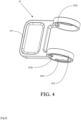
- the inner frame 21 may be treated as a cylindrical member extending in the second direction, one end thereof in the second direction is used for being connected to the showerhead bracket, and an opening of the other end is used for installation of the abutting piece and the elastic piece 25.
- An outer wall of the inner frame 21 is provided with annular clamping grooves 211 at positions close to both ends, and the annular clamping grooves 211 are used for forming a rotating connection and being fitted with the rotating member.
- the inner frame 21 is provided with an arc-shaped opening 213 on one side in the radial direction. The opening of the arc-shaped opening 213 faces the third direction and faces the vertical rail when the holder is installed on the vertical rail.
- the arc-shaped opening 213 is used for the abutting piece to protrude out of the inner frame 21.
- a slot is provided on the other side of the inner frame 21 opposite to the arc-shaped opening 213, and the slot extends in the second direction and is used for installation of the fixed frame 22.
- the outer wall of the inner frame 21 is further provided with an anti-rotation groove 212 extending in the axial direction, and the anti-rotation groove 212 may be fitted with the outer casing 31 to prevent the inner frame 21 from rotating relative to the outer casing 31 around its axial direction.
- the fixed frame 22 is provided with a sliding groove 223 extending in the second direction, and the abutting piece is installed in the sliding groove 223 and may slide in the sliding groove 223 in the third direction.
- Position-limiting plates are provided at both ends of the sliding groove 223 in the second direction.
- Two position-limiting plates are provided at the same end position, and a position-limiting groove 224 is formed between the two position-limiting plates.
- the position-limiting groove 224 may be fitted with the abutting piece to limit the sliding direction of the abutting piece and prevent the abutting piece from offsetting.
- a plurality of sliding buckles 221 are provided on upper edges of groove walls on both sides of the sliding groove 223.
- the sliding buckles 221 extend in the third direction and are provided with buckle structures.
- An elastic piece sleeving post 222 is disposed in the sliding groove 223 near one side of the groove wall.
- the elastic piece 25 is a spring
- the elastic piece 25 may be sleeved on the elastic piece sleeving post 222 to prevent the elastic piece 25 from being displaced.
- the outer casing 31 may be regarded as being formed by joining together two tubular members extending in the second direction and the first direction respectively, and joint positions of the two tubular members communicate with each other, so that inner cavities of the two tubular members fitted with each other and together form a cavity of the outer casing 31.
- the sleeve 32 is installed in the tubular member of the outer casing 31 extending in the first direction, and the sleeve 32 may be made of a material with a high friction coefficient such as rubber. A portion enclosed in a center of the sleeve 32 forms a sleeve portion 33, and the vertical rail may be inserted into the sleeve portion 33.
- an opening is provided in a side wall at a middle position of the sleeve 32.
- the opening is used for allowing the abutting piece to protrude into the sleeve portion 33, so that the abutting piece is allowed to abut against the vertical rail and be fitted with the inner wall of the sleeve portion 33 to be attached to the vertical rail, and the holder is thereby fixed onto the vertical rail.
- the outer casing 31 is provided with an anti-rotation rib which is matched with the anti-rotation groove 212 of the inner frame 21, and the anti-rotation rib may be inserted into the anti-rotation groove 212 to prevent the inner frame 21 from rotating relative to the outer casing 31 in the second direction.
- the abutting piece includes an abutting base 23 and an abutting block 24.
- the abutting base 23 is provided with clamping slots 232 corresponding to the sliding buckles 221 on the fixed frame 22 one-to-one.
- the sliding buckles 221 may be inserted into the clamping slots 232 and clamped to and fitted with the abutting base 23 through the buckle structures thereon. Since each sliding buckle 221 itself has a certain length, the abutting base 23 may slide in the extending direction of the sliding buckles 221. Further, the ends of the sliding buckles 221 are clamped to the abutting base 23, the abutting base 23 may not be separated from the fixed frame 22.
- An abutting block mounting groove 233 is provided in the middle of the abutting base 23.
- the elastic piece 25 is installed between the abutting base 23 and the fixed frame 22 and is used for applying a force to the abutting base 23 to keep the abutting piece in a state of abutting against the vertical rail when no external force is applied.
- each of two ends of the abutting base 23 in the second direction is provided with an abutting portion 231 for being fitted with the rotation piece through fitting of the inclined surfaces.
- the abutting portion 231 is provided with a first abutting surface 2311 and a second abutting surface 2312 whose ends are connected to each other in the first direction.
- the first abutting surface 2311 and the second abutting surface 2312 are fitted with other to form a "V"-shaped structure, and the opening of this "V"-shaped structure faces the third direction.
- first abutting surface 2311 and the second abutting surface 2312 are inclined surfaces, but in other embodiments, the first abutting surface 2311 and the second abutting surface 2312 may be arc surfaces.
- the two side walls of the abutting portion 231 in the first direction may also be fitted with the position-limiting groove 224 on the fixed frame 22, so that the sliding of the abutting base 23 in the third direction is further limited.
- the abutting block 24 is provided with an abutting block buckle 241, and the abutting block buckle 241 may be inserted into the abutting block mounting groove 233 on the abutting base 23 and is clamped and fixed to the abutting base 23.
- the abutting block 24 is provided with an abutting block frictional surface 242 facing the vertical rail.
- the abutting block frictional surface 242 may be made of materials such as rubber, so that a large frictional force may be formed between the abutting block frictional surface 242 and the vertical rail to ensure a sufficient attachment force to the vertical rail.
- the rotation piece is configured to be adapted to be fitted with the abutting piece through fitting of the inclined surfaces to drive the abutting piece away from the vertical rail through rotation, and the rotation piece includes a rotation base 27 and an abutting buckle 26.
- the rotation base 27 is provided with a toggle portion 271 and two transition portions 272.
- the transition portions 272 are disposed on one side of the toggle portion 271 and are located at two ends of the toggle portion 271 in the second direction.
- the toggle portion 271 is a plate-shaped member, and a user may push the toggle portion 271 by hand, so that the toggle portion 271 is inclined upwards or downwards in the first direction, thereby driving the entire rotation piece to rotate relative to the body.
- the toggle portion 271 is at a horizontal position.
- the first rotation position herein refers to the position at which the rotation piece is not being toggled.
- the transition portion 272 is a circular ring structure, and a clamping ring 2721 extending in a circumferential direction of an inner wall of the transition portion 272 protrudes from the inner wall.
- the clamping ring 2721 may be fitted with the annular clamping groove 211 on the outer wall of the inner frame 21, so that the rotation base 27 may be rotatably connected onto the inner frame 21, and that the rotation piece may rotate relative to the body.
- the inner wall of the transition portion 272 is further provided with an abutting buckle installation groove 2722.
- the abutting buckle installation groove 2722 is a groove-like structure with a "T"-shaped cross section, which may be clamped to, fitted with, and fixed to the abutting buckle 26.
- one end of the abutting buckle 26 is provided with a clamping portion 261.
- the cross section of the clamping portion 261 forms a "T"-shaped structure, so that the clamping portion 261 may be inserted into the abutting buckle installation groove 2722 from the side, and that the abutting buckle 26 and the rotation base 27 are clamped and fixed.
- An overlapping portion 262 protruding towards the second direction is provided at the other end of the abutting buckle 26.
- the overlapping portion 262 is provided with a tip end whose tip is facing the clamping portion 261, and two sides of the tip end extend outwards to form a first elastic arm 2621 and a second elastic arm 2622.
- the overlapping portion 262 may be fitted with the abutting portion 231 of the abutting base 23 in an overlapping manner, and an overlapping direction of the overlapping portion 262 faces the position where the toggle portion 271 is located.
- the cross-sectional view on the right side in FIG. 8 is a schematic view of a cross section B-B on the left side.
- the tip end of the overlapping portion 262 is just between the first abutting surface 2311 and the second abutting surface 2312.
- the first elastic arm 2621 and the second elastic arm 2622 respectively abut against the first abutting surface 2311 and the second abutting surface 2312.
- the abutting piece may be in a relatively stable state through the first elastic arm 2621 and the second elastic arm 2622, and the abutting piece thus is prevented from shaking.
- protrusions are provided at the ends of the first elastic arm 2621 and the second elastic arm 2622, and the protrusions may increase the degree of deformation of the first elastic arm 2621 and the second elastic arm 2622, so that the force exerted on the abutting piece is increased, and stability of the abutting piece is further improved.
- the showerhead bracket includes a showerhead base 11, a friction pad 12, a washer 13, and a screw 14.
- the showerhead base 11 is provided with a showerhead inserting portion 15, and a showerhead may be inserted into the showerhead inserting portion 15 to be fixed.
- the showerhead base 11 is fixed onto the inner frame 21 by the screw 14, so as to form a fixed connection with the body of the holder.
- the friction pad 12 is installed between the showerhead base 11 and the inner frame 21, and the washer 13 is installed between the screw 14 and the inner frame 21.
- the showerhead base 11 is installed onto the inner frame 21 first.
- one abutting buckle 26 is installed on the abutting buckle installation groove 2722 on the side of the rotating base 27 close to the showerhead base 11, and after the rotation base 27 is sleeved on the outer casing 31, the inner frame 21 and the showerhead base 11 are then inserted into the outer casing 31 from the end of the rotation base 27 away from the showerhead base 11.
- the abutting piece, the elastic piece 25, and the fixed frame 22 are assembled and are inserted into the outer casing 31, and the abutting base 23 on the abutting piece is aligned with the arc-shaped opening 213 on the inner frame 21.
- abutting buckle 26 is installed on the abutting buckle installation groove 2722 on the other side of the rotation base 27, and a decorative cover 41 is then clamped to the transition portion 272 of the rotation base 27.
- the sleeve 32 is installed on the outer casing 31.
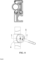
- the illustration in the middle position is a schematic view of the rotation piece in the first rotation position.
- the holder is attached to the vertical rail to be fixed onto the vertical rail.
- the holder may move upwards when the user toggles the rotation piece upwards, and the holder may move downwards when the user toggles the rotation piece downwards.
- the disclosure provides the vertical rail slider and the mobile showerhead holder.
- the abutting piece may be moved away from the vertical rail, so that the holder is released from the state of being attached to the vertical rail.
- the force of the user to toggle the rotation piece may accordingly push the holder up or down, and such operation is more convenient than that of an existing holder.
Landscapes
- Health & Medical Sciences (AREA)
- Life Sciences & Earth Sciences (AREA)
- Engineering & Computer Science (AREA)
- Hydrology & Water Resources (AREA)
- Public Health (AREA)
- Water Supply & Treatment (AREA)
- Emergency Lowering Means (AREA)
- Domestic Plumbing Installations (AREA)
Claims (10)
- Vertikaler Schienenschieber, konfiguriert, um an einer vertikalen, sich entlang einer ersten Richtung erstreckenden Schiene befestigt oder von dieser gelöst zu werden, damit er an der vertikalen Schiene befestigt werden oder sich relativ zu ihr bewegen kann, wobei der vertikale Schienenschieber umfasst:- einen sich entlang einer zweiten Richtung senkrecht zur ersten Richtung erstreckenden Körper, der mit einem Hülsenabschnitt (33) versehen ist, welcher so konfiguriert ist, dass er auf die vertikale Schiene aufgeschoben und mit ihr verbunden ist; ein Anlageteil, angepasst zum Verschieben entlang einer dritten Richtung, senkrecht zur ersten Richtung und zur zweiten Richtung, zwischen einer befestigten Position an der vertikalen Schiene, wobei das Anlageteil an der vertikalen Schiene anliegt, um mit dem Hülsenabschnitt (33) zusammenzupassen, und einer gelösten Position abgewandt von der vertikalen Schiene, wobei das Anlageteil mit einem Anlageabschnitt (231) versehen ist, der mit einer ersten Anlagefläche (2311) und einer zweiten Anlagefläche (2312) versehen ist, die v-förmige, geneigte Flächen bilden;- ein Rotationsteil, das drehbar mit dem Körper um eine Achse der zweiten Richtung verbunden ist, wobei das Rotationsteil eine Anlageschnalle (26) umfasst, die mit einem überlappenden Abschnitt (262) versehen ist, der durch Passung mit der ersten und zweiten Anlagefläche (2311, 2312) mit dem Anlageteil zusammenpasst, und wenn das Rotationsteil relativ zum Körper drehbar angetrieben wird, liegt der überlappende Abschnitt (262) schräg an der ersten Anlagefläche (2311) oder der zweiten Anlagefläche (2312) an, wodurch es das Anlageteil von der befestigten Position in die gelöste Position treibt; und- ein elastisches Teil (25), wobei zwei Enden des elastischen Teils (25) jeweils am Anlageteil und am Körper anliegen, um das Anlageteil zu drücken, damit es an der vertikalen Schiene anliegt, wenn keine äußere Kraft aufgebracht wird.
- Vertikaler Schienenschieber nach Anspruch 1, wobei sich die erste Anlagefläche (2311) und die zweite Anlagefläche (2312) in der ersten Richtung schneiden und eine Öffnung der von der ersten Anlagefläche (2311) und der zweiten Anlagefläche (2312) gebildeten v-förmigen Struktur der dritten Richtung zugewandt ist.
- Vertikaler Schienenschieber nach Anspruch 2, wobei der überlappende Abschnitt (262) mit einem ersten elastischen Arm (2621) und einem zweiten elastischen Arm (2622) versehen ist, die in der befestigten Position jeweils an der ersten Anlagefläche (2311) und der zweiten Anlagefläche (2312) anliegen.
- Vertikaler Schienenschieber nach Anspruch 3, wobei:- das Anlageteil einen Anlagesockel (23) und einen Anlageblock (24) umfasst, die fest miteinander verbunden sind, wobei der Anlagesockel (23) mit dem Körper verschiebbar verbunden ist,- zwei Enden des Anlagesockels (23) in der zweiten Richtung mit den Anlageabschnitten (231) versehen sind, jeder der Anlageabschnitte (231) mit der ersten Anlagefläche (2311) und der zweiten Anlagefläche (2312) versehen ist und die Öffnung des Schnittpunkts der ersten Anlagefläche (2311) und der zweiten Anlagefläche (2312) zur vertikalen Schiene zeigt,- der Anlageblock (24) mit einer der vertikalen Schiene zugewandten Anlageblock-Reibfläche (242) versehen ist.
- Vertikaler Schienenschieber nach Anspruch 4, wobei das Rotationsteil ferner einen Rotationssockel (27) umfasst, der Rotationssockel (27) mit einem Umschaltabschnitt (271) und einem Übergangsabschnitt (272) versehen ist, der Übergangsabschnitt (272) drehbar mit dem Körper verbunden ist und mit einer Anlageschnallen-Installationsnut (2722) versehen ist, ein Ende der Anlageschnalle (26) mit einem Klemmabschnitt versehen ist, der zum Einsetzen in die Anlageschnallen-Installationsnut (2722) geeignet ist, und der Umschaltabschnitt (271) so angepasst ist, dass er eine Kraft aufnimmt, um das Rotationsteil relativ zum Körper zu drehen, ein anderes Ende der Anlageschnalle (26) mit dem überlappenden Abschnitt (262) versehen ist.
- Vertikaler Schienenschieber nach Anspruch 4, wobei der Körper mit sich entlang der dritten Richtung erstreckenden Schiebeschnallen (221) versehen ist, der Anlagesockel (23) mit Klemmschlitzen (232) versehen ist, die Schiebeschnallen (221) so konfiguriert sind, dass sie zum Einsetzen in die Klemmschlitze (232) geeignet sind und mit dem Anlageteil geklemmt und befestigt sind, und das Anlageteil so konfiguriert ist, dass es zum Verschieben in einer sich erstreckenden Richtung der Schiebeschnallen (221) angepasst ist, um die Verschieberichtung des Anlagesockels (23) zu begrenzen und um ein Ablösen des Anlagesockels (23) vom Körper zu verhindern.
- Vertikaler Schienenschieber nach Anspruch 6, wobei:- der Körper einen Innenrahmen (21), einen festen Rahmen (22), ein Außengehäuse (31) und eine Hülse (32) umfasst, der Innenrahmen (21) fest mit dem Außengehäuse (31) verbunden ist, sich entlang der zweiten Richtung erstreckt und mit einer bogenförmigen Öffnung (213) versehen ist, die der dritten Richtung zugewandt ist, ein sich in die zweite Richtung erstreckender Schlitz auf derjenigen Seite vorgesehen ist, die der Seite, auf der die bogenförmige Öffnung (213) gebildet ist, gegenüberliegt, der Schlitz fest mit dem festen Rahmen (22) verbunden ist,- Zwei Enden des festen Rahmens (22) in der zweiten Richtung sind jeweils mit einer stellungsbegrenzenden Nut (224) versehen, die stellungsbegrenzende Nut (224) ist mit zwei Seitenwänden des Anlageabschnitts (231) in der ersten Richtung versehen, um das Verschieben des Anlagesockels (23) in der dritten Richtung zu begrenzen, und die Hülse (32) ist fest mit dem Außengehäuse (31) verbunden, der Hülsenabschnitt (33) ist auf der Hülse (32) vorgesehen.
- Vertikaler Schienenschieber nach Anspruch 7, wobei der feste Rahmen (22) mit einem Hülsenpfosten mit elastischem Teil (222) versehen ist, wobei das elastische Teil (25) eine Feder ist und auf den Hülsenpfosten mit elastischem Teil (222) aufgeschoben ist.
- Vertikaler Schienenschieber nach Anspruch 8, wobei ein Klemmring (2721), der sich in einer Umfangsrichtung einer Innenwand des Rotationssockels (27) erstreckt, aus der Innenwand der beiden Seiten des Rotationssockels (27) in die zweite Richtung herausragt, wobei eine Außenwand des Innenrahmens (21) an Positionen nahe beider Enden mit ringförmigen Klemmnuten (211) versehen ist, wobei der Klemmring (2721) mit der ringförmigen Klemmnut (211) versehen ist, so dass der Rotationssockel (27) drehbar mit dem Innenrahmen (21) verbunden ist.
- Mobiler Duschkopfhalter, umfassend den vertikalen Schienenschieber nach einem der Ansprüche 1 bis 9 und eine Duschkopfhalterung, wobei die Duschkopfhalterung fest mit dem Körper des vertikalen Schienenschiebers verbunden ist.
Applications Claiming Priority (1)
| Application Number | Priority Date | Filing Date | Title |
|---|---|---|---|
| CN202110916076.9A CN113585403B (zh) | 2021-08-10 | 2021-08-10 | 一种直杆移动装置和花洒移动架 |
Publications (2)
| Publication Number | Publication Date |
|---|---|
| EP4134495A1 EP4134495A1 (de) | 2023-02-15 |
| EP4134495B1 true EP4134495B1 (de) | 2025-04-16 |
Family
ID=78256965
Family Applications (1)
| Application Number | Title | Priority Date | Filing Date |
|---|---|---|---|
| EP22180786.0A Active EP4134495B1 (de) | 2021-08-10 | 2022-06-23 | Vertikaler schienengleiter und mobiler duschkopfhalter |
Country Status (3)
| Country | Link |
|---|---|
| US (1) | US11970848B2 (de) |
| EP (1) | EP4134495B1 (de) |
| CN (1) | CN113585403B (de) |
Families Citing this family (5)
| Publication number | Priority date | Publication date | Assignee | Title |
|---|---|---|---|---|
| CN116084513B (zh) * | 2022-01-25 | 2026-04-24 | 福建省德牧卫浴科技有限公司 | 一种滑动调节装置及其调节方法 |
| CN114855946B (zh) * | 2022-03-25 | 2023-08-22 | 厦门欧圣斯卫浴有限公司 | 一种推钮滑座 |
| FR3139145B1 (fr) * | 2022-08-26 | 2024-11-01 | Pellet Asc | Suppport de douche avec réglage coulissant sans effort |
| CN116180849A (zh) * | 2023-02-27 | 2023-05-30 | 福建西河卫浴科技有限公司 | 一种滑动停靠机构及滑动停靠组件 |
| CN117344828A (zh) * | 2023-11-21 | 2024-01-05 | 厦门普美霖卫浴科技有限公司 | 一种滑套 |
Family Cites Families (7)
| Publication number | Priority date | Publication date | Assignee | Title |
|---|---|---|---|---|
| DE19827350A1 (de) * | 1998-06-19 | 1999-12-30 | Wilke Heinrich Hewi Gmbh | Vorrichtung zur verschiebbaren Montage eines Gegenstands, insbesondere einer Handbrause, an einer Tragstange |
| JP4906574B2 (ja) * | 2007-04-24 | 2012-03-28 | ナカ工業株式会社 | 可動式シャワーフック |
| CA2691121C (en) * | 2010-01-25 | 2012-09-04 | Globe Union Industrial Corp. | Movable support seat for a shower head |
| CN102824132B (zh) * | 2012-08-29 | 2015-05-06 | 厦门建霖工业有限公司 | 升降杆滑动座 |
| CN208604693U (zh) * | 2018-06-15 | 2019-03-15 | 厦门建霖健康家居股份有限公司 | 一种便携式升降杆易滑滑座结构 |
| CN110042888B (zh) * | 2019-03-25 | 2024-06-11 | 沛乐迪(厦门)科技有限公司 | 一种升降花洒插座自锁结构 |
| CN211774224U (zh) * | 2019-11-29 | 2020-10-27 | 福建西河卫浴科技有限公司 | 一种按钮式移动架 |
-
2021
- 2021-08-10 CN CN202110916076.9A patent/CN113585403B/zh active Active
-
2022
- 2022-06-19 US US17/844,046 patent/US11970848B2/en active Active
- 2022-06-23 EP EP22180786.0A patent/EP4134495B1/de active Active
Also Published As
| Publication number | Publication date |
|---|---|
| CN113585403A (zh) | 2021-11-02 |
| EP4134495A1 (de) | 2023-02-15 |
| US20230049835A1 (en) | 2023-02-16 |
| US11970848B2 (en) | 2024-04-30 |
| CN113585403B (zh) | 2024-08-06 |
Similar Documents
| Publication | Publication Date | Title |
|---|---|---|
| EP4134495B1 (de) | Vertikaler schienengleiter und mobiler duschkopfhalter | |
| US6367787B1 (en) | Hand clamp | |
| EP2174882B1 (de) | Vakuumverschlusskappe | |
| EP1878928B1 (de) | Saugnapfvorrichtung, insbesondere für die Windschutzscheibe eines Kraftfahrzeugs | |
| US9267518B2 (en) | Holder mechanism | |
| JPH02174942A (ja) | ピペット装置 | |
| CN108883542B (zh) | 具有用于接合与脱离剃须刀架的锁定和释放机构的剃须刀手柄 | |
| CA2342122A1 (fr) | Bouton-poussoir a effet ressort | |
| JPH10502304A (ja) | 掃除具を解離可能に固定するための装置 | |
| US10694898B2 (en) | Sliding seat of lifting rod | |
| JPH0150409B2 (de) | ||
| HU220401B (hu) | Rögzíthető csúszótag zuhanytartó rúdhoz | |
| CA2478532A1 (en) | Coupling apparatus including release preventing structure | |
| JP2008267054A (ja) | 可動式シャワーフック | |
| JP3156463U (ja) | 人形体 | |
| CN216280262U (zh) | 电子设备支架 | |
| CA2523613C (en) | Holder assembly | |
| JP3157712B2 (ja) | 係合二軸のストッパー | |
| CN224016432U (zh) | 一种花洒滑座 | |
| JPH1091337A (ja) | マウスパッド | |
| CN115869613A (zh) | 具有优选检测准确度的游戏杆 | |
| JP2017144500A (ja) | 部品組み付け治具 | |
| CN113026873A (zh) | 一种滑座及滑座在杆体上的升降调节方法 | |
| JPH063287Y2 (ja) | ホームごたつ用脚 | |
| CN223450759U (zh) | 一种旋转按压式档位开关及榨汁机 |
Legal Events
| Date | Code | Title | Description |
|---|---|---|---|
| PUAI | Public reference made under article 153(3) epc to a published international application that has entered the european phase |
Free format text: ORIGINAL CODE: 0009012 |
|
| STAA | Information on the status of an ep patent application or granted ep patent |
Free format text: STATUS: THE APPLICATION HAS BEEN PUBLISHED |
|
| AK | Designated contracting states |
Kind code of ref document: A1 Designated state(s): AL AT BE BG CH CY CZ DE DK EE ES FI FR GB GR HR HU IE IS IT LI LT LU LV MC MK MT NL NO PL PT RO RS SE SI SK SM TR |
|
| STAA | Information on the status of an ep patent application or granted ep patent |
Free format text: STATUS: REQUEST FOR EXAMINATION WAS MADE |
|
| 17P | Request for examination filed |
Effective date: 20230814 |
|
| RBV | Designated contracting states (corrected) |
Designated state(s): AL AT BE BG CH CY CZ DE DK EE ES FI FR GB GR HR HU IE IS IT LI LT LU LV MC MK MT NL NO PL PT RO RS SE SI SK SM TR |
|
| GRAP | Despatch of communication of intention to grant a patent |
Free format text: ORIGINAL CODE: EPIDOSNIGR1 |
|
| STAA | Information on the status of an ep patent application or granted ep patent |
Free format text: STATUS: GRANT OF PATENT IS INTENDED |
|
| INTG | Intention to grant announced |
Effective date: 20241126 |
|
| RIN1 | Information on inventor provided before grant (corrected) |
Inventor name: LIU, QIQIAO Inventor name: DENG, XIAOQING Inventor name: DENG, FEIMING Inventor name: CHEN, ZHIWEI Inventor name: LIN, XIAOSHAN Inventor name: LIN, XIAOFA |
|
| GRAS | Grant fee paid |
Free format text: ORIGINAL CODE: EPIDOSNIGR3 |
|
| GRAA | (expected) grant |
Free format text: ORIGINAL CODE: 0009210 |
|
| STAA | Information on the status of an ep patent application or granted ep patent |
Free format text: STATUS: THE PATENT HAS BEEN GRANTED |
|
| AK | Designated contracting states |
Kind code of ref document: B1 Designated state(s): AL AT BE BG CH CY CZ DE DK EE ES FI FR GB GR HR HU IE IS IT LI LT LU LV MC MK MT NL NO PL PT RO RS SE SI SK SM TR |
|
| REG | Reference to a national code |
Ref country code: GB Ref legal event code: FG4D |
|
| REG | Reference to a national code |
Ref country code: CH Ref legal event code: EP Ref country code: DE Ref legal event code: R096 Ref document number: 602022013137 Country of ref document: DE |
|
| REG | Reference to a national code |
Ref country code: IE Ref legal event code: FG4D |
|
| P01 | Opt-out of the competence of the unified patent court (upc) registered |
Free format text: CASE NUMBER: APP_20544/2025 Effective date: 20250430 |
|
| PGFP | Annual fee paid to national office [announced via postgrant information from national office to epo] |
Ref country code: FR Payment date: 20250627 Year of fee payment: 4 |
|
| PGFP | Annual fee paid to national office [announced via postgrant information from national office to epo] |
Ref country code: AT Payment date: 20250721 Year of fee payment: 4 |
|
| REG | Reference to a national code |
Ref country code: NL Ref legal event code: MP Effective date: 20250416 |
|
| PG25 | Lapsed in a contracting state [announced via postgrant information from national office to epo] |
Ref country code: NL Free format text: LAPSE BECAUSE OF FAILURE TO SUBMIT A TRANSLATION OF THE DESCRIPTION OR TO PAY THE FEE WITHIN THE PRESCRIBED TIME-LIMIT Effective date: 20250416 |
|
| REG | Reference to a national code |
Ref country code: AT Ref legal event code: MK05 Ref document number: 1785760 Country of ref document: AT Kind code of ref document: T Effective date: 20250416 |
|
| PG25 | Lapsed in a contracting state [announced via postgrant information from national office to epo] |
Ref country code: FI Free format text: LAPSE BECAUSE OF FAILURE TO SUBMIT A TRANSLATION OF THE DESCRIPTION OR TO PAY THE FEE WITHIN THE PRESCRIBED TIME-LIMIT Effective date: 20250416 Ref country code: ES Free format text: LAPSE BECAUSE OF FAILURE TO SUBMIT A TRANSLATION OF THE DESCRIPTION OR TO PAY THE FEE WITHIN THE PRESCRIBED TIME-LIMIT Effective date: 20250416 Ref country code: PT Free format text: LAPSE BECAUSE OF FAILURE TO SUBMIT A TRANSLATION OF THE DESCRIPTION OR TO PAY THE FEE WITHIN THE PRESCRIBED TIME-LIMIT Effective date: 20250818 |
|
| PGFP | Annual fee paid to national office [announced via postgrant information from national office to epo] |
Ref country code: DE Payment date: 20250627 Year of fee payment: 4 |
|
| REG | Reference to a national code |
Ref country code: LT Ref legal event code: MG9D |
|
| PG25 | Lapsed in a contracting state [announced via postgrant information from national office to epo] |
Ref country code: NO Free format text: LAPSE BECAUSE OF FAILURE TO SUBMIT A TRANSLATION OF THE DESCRIPTION OR TO PAY THE FEE WITHIN THE PRESCRIBED TIME-LIMIT Effective date: 20250716 Ref country code: GR Free format text: LAPSE BECAUSE OF FAILURE TO SUBMIT A TRANSLATION OF THE DESCRIPTION OR TO PAY THE FEE WITHIN THE PRESCRIBED TIME-LIMIT Effective date: 20250717 |
|
| PG25 | Lapsed in a contracting state [announced via postgrant information from national office to epo] |
Ref country code: PL Free format text: LAPSE BECAUSE OF FAILURE TO SUBMIT A TRANSLATION OF THE DESCRIPTION OR TO PAY THE FEE WITHIN THE PRESCRIBED TIME-LIMIT Effective date: 20250416 |
|
| PG25 | Lapsed in a contracting state [announced via postgrant information from national office to epo] |
Ref country code: BG Free format text: LAPSE BECAUSE OF FAILURE TO SUBMIT A TRANSLATION OF THE DESCRIPTION OR TO PAY THE FEE WITHIN THE PRESCRIBED TIME-LIMIT Effective date: 20250416 |
|
| PG25 | Lapsed in a contracting state [announced via postgrant information from national office to epo] |
Ref country code: HR Free format text: LAPSE BECAUSE OF FAILURE TO SUBMIT A TRANSLATION OF THE DESCRIPTION OR TO PAY THE FEE WITHIN THE PRESCRIBED TIME-LIMIT Effective date: 20250416 Ref country code: AT Free format text: LAPSE BECAUSE OF FAILURE TO SUBMIT A TRANSLATION OF THE DESCRIPTION OR TO PAY THE FEE WITHIN THE PRESCRIBED TIME-LIMIT Effective date: 20250416 |
|
| PG25 | Lapsed in a contracting state [announced via postgrant information from national office to epo] |
Ref country code: RS Free format text: LAPSE BECAUSE OF FAILURE TO SUBMIT A TRANSLATION OF THE DESCRIPTION OR TO PAY THE FEE WITHIN THE PRESCRIBED TIME-LIMIT Effective date: 20250716 |
|
| PG25 | Lapsed in a contracting state [announced via postgrant information from national office to epo] |
Ref country code: IS Free format text: LAPSE BECAUSE OF FAILURE TO SUBMIT A TRANSLATION OF THE DESCRIPTION OR TO PAY THE FEE WITHIN THE PRESCRIBED TIME-LIMIT Effective date: 20250816 |
|
| PG25 | Lapsed in a contracting state [announced via postgrant information from national office to epo] |
Ref country code: LV Free format text: LAPSE BECAUSE OF FAILURE TO SUBMIT A TRANSLATION OF THE DESCRIPTION OR TO PAY THE FEE WITHIN THE PRESCRIBED TIME-LIMIT Effective date: 20250416 |
|
| PG25 | Lapsed in a contracting state [announced via postgrant information from national office to epo] |
Ref country code: DK Free format text: LAPSE BECAUSE OF FAILURE TO SUBMIT A TRANSLATION OF THE DESCRIPTION OR TO PAY THE FEE WITHIN THE PRESCRIBED TIME-LIMIT Effective date: 20250416 Ref country code: SM Free format text: LAPSE BECAUSE OF FAILURE TO SUBMIT A TRANSLATION OF THE DESCRIPTION OR TO PAY THE FEE WITHIN THE PRESCRIBED TIME-LIMIT Effective date: 20250416 |
|
| REG | Reference to a national code |
Ref country code: DE Ref legal event code: R097 Ref document number: 602022013137 Country of ref document: DE |
|
| PG25 | Lapsed in a contracting state [announced via postgrant information from national office to epo] |
Ref country code: CZ Free format text: LAPSE BECAUSE OF FAILURE TO SUBMIT A TRANSLATION OF THE DESCRIPTION OR TO PAY THE FEE WITHIN THE PRESCRIBED TIME-LIMIT Effective date: 20250416 |
|
| PG25 | Lapsed in a contracting state [announced via postgrant information from national office to epo] |
Ref country code: EE Free format text: LAPSE BECAUSE OF FAILURE TO SUBMIT A TRANSLATION OF THE DESCRIPTION OR TO PAY THE FEE WITHIN THE PRESCRIBED TIME-LIMIT Effective date: 20250416 |
|
| PG25 | Lapsed in a contracting state [announced via postgrant information from national office to epo] |
Ref country code: SK Free format text: LAPSE BECAUSE OF FAILURE TO SUBMIT A TRANSLATION OF THE DESCRIPTION OR TO PAY THE FEE WITHIN THE PRESCRIBED TIME-LIMIT Effective date: 20250416 |
|
| REG | Reference to a national code |
Ref country code: CH Ref legal event code: H13 Free format text: ST27 STATUS EVENT CODE: U-0-0-H10-H13 (AS PROVIDED BY THE NATIONAL OFFICE) Effective date: 20260127 |
|
| PG25 | Lapsed in a contracting state [announced via postgrant information from national office to epo] |
Ref country code: IT Free format text: LAPSE BECAUSE OF FAILURE TO SUBMIT A TRANSLATION OF THE DESCRIPTION OR TO PAY THE FEE WITHIN THE PRESCRIBED TIME-LIMIT Effective date: 20250416 |
|
| PG25 | Lapsed in a contracting state [announced via postgrant information from national office to epo] |
Ref country code: MC Free format text: LAPSE BECAUSE OF FAILURE TO SUBMIT A TRANSLATION OF THE DESCRIPTION OR TO PAY THE FEE WITHIN THE PRESCRIBED TIME-LIMIT Effective date: 20250416 |
|
| PG25 | Lapsed in a contracting state [announced via postgrant information from national office to epo] |
Ref country code: RO Free format text: LAPSE BECAUSE OF FAILURE TO SUBMIT A TRANSLATION OF THE DESCRIPTION OR TO PAY THE FEE WITHIN THE PRESCRIBED TIME-LIMIT Effective date: 20250416 |
|
| PG25 | Lapsed in a contracting state [announced via postgrant information from national office to epo] |
Ref country code: LU Free format text: LAPSE BECAUSE OF NON-PAYMENT OF DUE FEES Effective date: 20250623 |
|
| PLBE | No opposition filed within time limit |
Free format text: ORIGINAL CODE: 0009261 |
|
| STAA | Information on the status of an ep patent application or granted ep patent |
Free format text: STATUS: NO OPPOSITION FILED WITHIN TIME LIMIT |
|
| REG | Reference to a national code |
Ref country code: CH Ref legal event code: L10 Free format text: ST27 STATUS EVENT CODE: U-0-0-L10-L00 (AS PROVIDED BY THE NATIONAL OFFICE) Effective date: 20260225 |
|
| REG | Reference to a national code |
Ref country code: BE Ref legal event code: MM Effective date: 20250630 |
|
| 26N | No opposition filed |
Effective date: 20260119 |
|
| PG25 | Lapsed in a contracting state [announced via postgrant information from national office to epo] |
Ref country code: IE Free format text: LAPSE BECAUSE OF NON-PAYMENT OF DUE FEES Effective date: 20250623 |
|
| PG25 | Lapsed in a contracting state [announced via postgrant information from national office to epo] |
Ref country code: BE Free format text: LAPSE BECAUSE OF NON-PAYMENT OF DUE FEES Effective date: 20250630 |
|
| PG25 | Lapsed in a contracting state [announced via postgrant information from national office to epo] |
Ref country code: CH Free format text: LAPSE BECAUSE OF NON-PAYMENT OF DUE FEES Effective date: 20250630 |