EP4134279B1 - Indirektes rücksichtsystem mit indexgeometrie umfassend eine verstellkugel mit überdrehindexierung - Google Patents
Indirektes rücksichtsystem mit indexgeometrie umfassend eine verstellkugel mit überdrehindexierung Download PDFInfo
- Publication number
- EP4134279B1 EP4134279B1 EP22163726.7A EP22163726A EP4134279B1 EP 4134279 B1 EP4134279 B1 EP 4134279B1 EP 22163726 A EP22163726 A EP 22163726A EP 4134279 B1 EP4134279 B1 EP 4134279B1
- Authority
- EP
- European Patent Office
- Prior art keywords
- groove
- viewing system
- indirect
- rear viewing
- projection
- Prior art date
- Legal status (The legal status is an assumption and is not a legal conclusion. Google has not performed a legal analysis and makes no representation as to the accuracy of the status listed.)
- Active
Links
Images




Classifications
-
- B—PERFORMING OPERATIONS; TRANSPORTING
- B60—VEHICLES IN GENERAL
- B60R—VEHICLES, VEHICLE FITTINGS, OR VEHICLE PARTS, NOT OTHERWISE PROVIDED FOR
- B60R1/00—Optical viewing arrangements; Real-time viewing arrangements for drivers or passengers using optical image capturing systems, e.g. cameras or video systems specially adapted for use in or on vehicles
- B60R1/02—Rear-view mirror arrangements
- B60R1/06—Rear-view mirror arrangements mounted on vehicle exterior
- B60R1/062—Rear-view mirror arrangements mounted on vehicle exterior with remote control for adjusting position
- B60R1/064—Rear-view mirror arrangements mounted on vehicle exterior with remote control for adjusting position by manually powered actuators
- B60R1/066—Rear-view mirror arrangements mounted on vehicle exterior with remote control for adjusting position by manually powered actuators for adjusting the mirror relative to its housing
-
- B—PERFORMING OPERATIONS; TRANSPORTING
- B60—VEHICLES IN GENERAL
- B60R—VEHICLES, VEHICLE FITTINGS, OR VEHICLE PARTS, NOT OTHERWISE PROVIDED FOR
- B60R1/00—Optical viewing arrangements; Real-time viewing arrangements for drivers or passengers using optical image capturing systems, e.g. cameras or video systems specially adapted for use in or on vehicles
- B60R1/02—Rear-view mirror arrangements
- B60R1/08—Rear-view mirror arrangements involving special optical features, e.g. avoiding blind spots, e.g. convex mirrors; Side-by-side associations of rear-view and other mirrors
- B60R1/081—Rear-view mirror arrangements involving special optical features, e.g. avoiding blind spots, e.g. convex mirrors; Side-by-side associations of rear-view and other mirrors avoiding blind spots, e.g. by using a side-by-side association of mirrors
- B60R1/082—Rear-view mirror arrangements involving special optical features, e.g. avoiding blind spots, e.g. convex mirrors; Side-by-side associations of rear-view and other mirrors avoiding blind spots, e.g. by using a side-by-side association of mirrors using a single wide field mirror or an association of rigidly connected mirrors
-
- B—PERFORMING OPERATIONS; TRANSPORTING
- B60—VEHICLES IN GENERAL
- B60R—VEHICLES, VEHICLE FITTINGS, OR VEHICLE PARTS, NOT OTHERWISE PROVIDED FOR
- B60R1/00—Optical viewing arrangements; Real-time viewing arrangements for drivers or passengers using optical image capturing systems, e.g. cameras or video systems specially adapted for use in or on vehicles
- B60R1/02—Rear-view mirror arrangements
- B60R1/04—Rear-view mirror arrangements mounted inside vehicle
-
- B—PERFORMING OPERATIONS; TRANSPORTING
- B60—VEHICLES IN GENERAL
- B60R—VEHICLES, VEHICLE FITTINGS, OR VEHICLE PARTS, NOT OTHERWISE PROVIDED FOR
- B60R1/00—Optical viewing arrangements; Real-time viewing arrangements for drivers or passengers using optical image capturing systems, e.g. cameras or video systems specially adapted for use in or on vehicles
- B60R1/02—Rear-view mirror arrangements
- B60R1/06—Rear-view mirror arrangements mounted on vehicle exterior
-
- B—PERFORMING OPERATIONS; TRANSPORTING
- B60—VEHICLES IN GENERAL
- B60R—VEHICLES, VEHICLE FITTINGS, OR VEHICLE PARTS, NOT OTHERWISE PROVIDED FOR
- B60R1/00—Optical viewing arrangements; Real-time viewing arrangements for drivers or passengers using optical image capturing systems, e.g. cameras or video systems specially adapted for use in or on vehicles
- B60R1/02—Rear-view mirror arrangements
- B60R1/06—Rear-view mirror arrangements mounted on vehicle exterior
- B60R1/076—Rear-view mirror arrangements mounted on vehicle exterior yieldable to excessive external force and provided with an indexed use position
-
- B—PERFORMING OPERATIONS; TRANSPORTING
- B60—VEHICLES IN GENERAL
- B60R—VEHICLES, VEHICLE FITTINGS, OR VEHICLE PARTS, NOT OTHERWISE PROVIDED FOR
- B60R1/00—Optical viewing arrangements; Real-time viewing arrangements for drivers or passengers using optical image capturing systems, e.g. cameras or video systems specially adapted for use in or on vehicles
- B60R1/02—Rear-view mirror arrangements
- B60R1/06—Rear-view mirror arrangements mounted on vehicle exterior
- B60R1/078—Rear-view mirror arrangements mounted on vehicle exterior easily removable; mounted for bodily outward movement, e.g. when towing
-
- F—MECHANICAL ENGINEERING; LIGHTING; HEATING; WEAPONS; BLASTING
- F16—ENGINEERING ELEMENTS AND UNITS; GENERAL MEASURES FOR PRODUCING AND MAINTAINING EFFECTIVE FUNCTIONING OF MACHINES OR INSTALLATIONS; THERMAL INSULATION IN GENERAL
- F16B—DEVICES FOR FASTENING OR SECURING CONSTRUCTIONAL ELEMENTS OR MACHINE PARTS TOGETHER, e.g. NAILS, BOLTS, CIRCLIPS, CLAMPS, CLIPS OR WEDGES; JOINTS OR JOINTING
- F16B2/00—Friction-grip releasable fastenings
- F16B2/02—Clamps, i.e. with gripping action effected by positive means other than the inherent resistance to deformation of the material of the fastening
-
- F—MECHANICAL ENGINEERING; LIGHTING; HEATING; WEAPONS; BLASTING
- F16—ENGINEERING ELEMENTS AND UNITS; GENERAL MEASURES FOR PRODUCING AND MAINTAINING EFFECTIVE FUNCTIONING OF MACHINES OR INSTALLATIONS; THERMAL INSULATION IN GENERAL
- F16C—SHAFTS; FLEXIBLE SHAFTS; ELEMENTS OR CRANKSHAFT MECHANISMS; ROTARY BODIES OTHER THAN GEARING ELEMENTS; BEARINGS
- F16C11/00—Pivots; Pivotal connections
- F16C11/04—Pivotal connections
- F16C11/06—Ball-joints; Other joints having more than one degree of angular freedom, i.e. universal joints
- F16C11/0604—Construction of the male part
-
- F—MECHANICAL ENGINEERING; LIGHTING; HEATING; WEAPONS; BLASTING
- F16—ENGINEERING ELEMENTS AND UNITS; GENERAL MEASURES FOR PRODUCING AND MAINTAINING EFFECTIVE FUNCTIONING OF MACHINES OR INSTALLATIONS; THERMAL INSULATION IN GENERAL
- F16C—SHAFTS; FLEXIBLE SHAFTS; ELEMENTS OR CRANKSHAFT MECHANISMS; ROTARY BODIES OTHER THAN GEARING ELEMENTS; BEARINGS
- F16C11/00—Pivots; Pivotal connections
- F16C11/04—Pivotal connections
- F16C11/06—Ball-joints; Other joints having more than one degree of angular freedom, i.e. universal joints
- F16C11/0614—Ball-joints; Other joints having more than one degree of angular freedom, i.e. universal joints the female part of the joint being open on two sides
-
- F—MECHANICAL ENGINEERING; LIGHTING; HEATING; WEAPONS; BLASTING
- F16—ENGINEERING ELEMENTS AND UNITS; GENERAL MEASURES FOR PRODUCING AND MAINTAINING EFFECTIVE FUNCTIONING OF MACHINES OR INSTALLATIONS; THERMAL INSULATION IN GENERAL
- F16C—SHAFTS; FLEXIBLE SHAFTS; ELEMENTS OR CRANKSHAFT MECHANISMS; ROTARY BODIES OTHER THAN GEARING ELEMENTS; BEARINGS
- F16C11/00—Pivots; Pivotal connections
- F16C11/04—Pivotal connections
- F16C11/06—Ball-joints; Other joints having more than one degree of angular freedom, i.e. universal joints
- F16C11/0695—Mounting of ball-joints, e.g. fixing them to a connecting rod
-
- F—MECHANICAL ENGINEERING; LIGHTING; HEATING; WEAPONS; BLASTING
- F16—ENGINEERING ELEMENTS AND UNITS; GENERAL MEASURES FOR PRODUCING AND MAINTAINING EFFECTIVE FUNCTIONING OF MACHINES OR INSTALLATIONS; THERMAL INSULATION IN GENERAL
- F16C—SHAFTS; FLEXIBLE SHAFTS; ELEMENTS OR CRANKSHAFT MECHANISMS; ROTARY BODIES OTHER THAN GEARING ELEMENTS; BEARINGS
- F16C11/00—Pivots; Pivotal connections
- F16C11/04—Pivotal connections
- F16C11/10—Arrangements for locking
-
- G—PHYSICS
- G02—OPTICS
- G02B—OPTICAL ELEMENTS, SYSTEMS OR APPARATUS
- G02B7/00—Mountings, adjusting means, or light-tight connections, for optical elements
- G02B7/18—Mountings, adjusting means, or light-tight connections, for optical elements for prisms; for mirrors
- G02B7/182—Mountings, adjusting means, or light-tight connections, for optical elements for prisms; for mirrors for mirrors
-
- F—MECHANICAL ENGINEERING; LIGHTING; HEATING; WEAPONS; BLASTING
- F16—ENGINEERING ELEMENTS AND UNITS; GENERAL MEASURES FOR PRODUCING AND MAINTAINING EFFECTIVE FUNCTIONING OF MACHINES OR INSTALLATIONS; THERMAL INSULATION IN GENERAL
- F16C—SHAFTS; FLEXIBLE SHAFTS; ELEMENTS OR CRANKSHAFT MECHANISMS; ROTARY BODIES OTHER THAN GEARING ELEMENTS; BEARINGS
- F16C2326/00—Articles relating to transporting
- F16C2326/01—Parts of vehicles in general
-
- F—MECHANICAL ENGINEERING; LIGHTING; HEATING; WEAPONS; BLASTING
- F16—ENGINEERING ELEMENTS AND UNITS; GENERAL MEASURES FOR PRODUCING AND MAINTAINING EFFECTIVE FUNCTIONING OF MACHINES OR INSTALLATIONS; THERMAL INSULATION IN GENERAL
- F16C—SHAFTS; FLEXIBLE SHAFTS; ELEMENTS OR CRANKSHAFT MECHANISMS; ROTARY BODIES OTHER THAN GEARING ELEMENTS; BEARINGS
- F16C2326/00—Articles relating to transporting
- F16C2326/20—Land vehicles
-
- Y—GENERAL TAGGING OF NEW TECHNOLOGICAL DEVELOPMENTS; GENERAL TAGGING OF CROSS-SECTIONAL TECHNOLOGIES SPANNING OVER SEVERAL SECTIONS OF THE IPC; TECHNICAL SUBJECTS COVERED BY FORMER USPC CROSS-REFERENCE ART COLLECTIONS [XRACs] AND DIGESTS
- Y02—TECHNOLOGIES OR APPLICATIONS FOR MITIGATION OR ADAPTATION AGAINST CLIMATE CHANGE
- Y02T—CLIMATE CHANGE MITIGATION TECHNOLOGIES RELATED TO TRANSPORTATION
- Y02T10/00—Road transport of goods or passengers
- Y02T10/80—Technologies aiming to reduce greenhouse gasses emissions common to all road transportation technologies
- Y02T10/86—Optimisation of rolling resistance, e.g. weight reduction
Definitions
- the invention relates to an indirect rear-view system for a motor vehicle, such as a commercial vehicle, an agricultural/construction machine, e.g. a tractor, or a truck, a bus and/or a transporter, with a support element for fastening at least one reflection element, such as a mirror glass, wherein the support element has a coupling region for positionally variable fastening/attachment to an adjustment element that can be connected to the vehicle or is connected to the vehicle, wherein the coupling region contacts a counter-contact region of the adjustment element, wherein interlocking anti-twist means are also present on the support element and the adjustment element, for example according to the tongue and groove principle.
- a motor vehicle such as a commercial vehicle, an agricultural/construction machine, e.g. a tractor, or a truck, a bus and/or a transporter
- a support element for fastening at least one reflection element such as a mirror glass
- the support element has a coupling region for positionally variable fastening/attachment to an
- a joint arrangement is protected there, namely a joint device for arranging two components at an angle to one another, in particular for rear-view mirrors with adjustable mirror panes, with a first joint component with a ball socket, a second joint component which has a projection essentially in the shape of a spherical segment which is fitted into the ball socket, a sliding part, and a connecting device for producing a clamping connection between the first joint component, sliding part and second joint component, wherein the mutually facing sides of the ball socket, sliding part and projection each have a convex structure and a concave structure designed to complement this, wherein the structures define a first and a second axis of rotation between the sliding part, ball socket and projection.
- the concave structure is more curved than the convex structure, at least in the unloaded state.
- the applicant is also the holder of the European patent EP 3 335 938 B1
- This patent protects a ball joint device for the adjustable arrangement of a first and a second joint component around a pivot point.
- the patented ball joint device has a spherical surface element on the first joint component with an outer side that is part of a spherical surface and has a first radius of curvature with a first center point.
- An engagement device on the second joint component which contacts the spherical surface element with a first contact surface, is also present.
- This device also has a concave spherical cap-shaped receptacle on the first or second joint component, which is arranged within the spherical surface element and has a second radius of curvature with a second center point.
- the second or first joint component has a concave spherical cap.
- the second or first joint component has a convex spherical cap, which is supported with a second contact surface in the spherical cap-shaped receptacle.
- the first radius of curvature is larger than the second radius of curvature.
- the insert device engages over the spherical surface element and the two joint components in the manner of a snap fastener connection.
- the spherical surface element is partially designed in the shape of a spherical ring and that the spherical surface element has a plurality of spherical ring-shaped sections distributed over the circumference.
- the JP 2018 - 154 287 A discloses a side mirror comprising a rod provided with a spherical portion at a tip; a housing in which a recessed spherical surface portion is provided in a connecting portion on its inner side, which is attached to a mirror surface body and into which the spherical portion is fitted; a holding plate provided with a recessed spherical surface portion paired with the recessed spherical portion, arranged opposite to the connecting portion to surround the spherical portion between the mutual recessed spherical surface portions, and vibratably holds the spherical portion in the connecting portion; and a vibration range regulating plate manually and rotatably in a horizontal direction between a housing-side support groove provided in the connecting portion and a holder plate side support groove formed in the holder plate, and regulates a vibration range of the housing from an unrestrained position to a maximum restricted position.
- the US 5 755 526 A discloses a ball joint comprising a socket having a chamber.
- a ball stud includes a ball end. The ball end is movable relative to the socket in a first direction into the chamber in the socket.
- the socket has first portions engageable with the ball end to block rotation of the ball end about a first axis during movement of the ball end into the chamber.
- a resilient retainer is deflected during movement of the ball head into the chamber. When the ball end is in the chamber, the retainer straightens to rotate the ball end to an operative position in the chamber.
- the socket has second portions engageable with the ball head to block movement of the ball head out of the chamber when the ball head is in the operative position. Engagement of the retainer with a retainer opening in the socket blocks rotation of the ball end from the operative position.
- the rotation stop means form an index geometry which, in a first operating state, allows an adjustment/pivoting of the support element relative to the adjustment element about two axes of rotation which are transverse to one another, preferably orthogonal to one another, and in a second operating state allows a change in the basic position/an adjustment/pivoting of the support element relative to the adjustment element about a third axis of rotation which is oriented transversely to the other two axes of rotation, preferably orthogonal to them.
- Anti-twist means are understood to mean means which, in at least one specific operating state, in particular the first operating state, make it impossible for the support element to rotate relative to the twisting element about a specific axis of rotation, while still allowing rotation/pivoting about two further axes orthogonal thereto.
- a first basic position can be left and, after a sliding movement of the support element relative to the adjustment element, a second basic position can be assumed. There, engagement preferably takes place, for example by snapping.
- the anti-rotation means prevent pivoting about a further axis, i.e. about a second horizontal/transverse axis which is orthogonal to both the vertical/upright axis and the first horizontal/transverse axis.
- the number of geometrically necessary variants shows that different connection conditions exist. This can mean, for example, that a support structure must be connected horizontally (also left / right) to a mirror head and that a vertical (top / bottom) connection is preferred for other vehicles. This creates a large number of variants that must be provided.
- the invention now makes this possible.
- an indirect vision system is provided for a vehicle that has few geometric variants and realizes many connections to a wide variety of vehicles or vehicle variants.
- tongue and groove connection can now also be designed in different geometric shapes, e.g. trapezoidal or wave-shaped.
- the invention relates to an indirect vision system for a vehicle comprising at least one reflection element for indirect vision, a support element and an adjustment element, wherein the support element accommodates the reflection element, and wherein the support element and the adjustment element can be pivoted relative to one another via spherical contact areas via a pivot point, wherein the special feature is that various operating positions between the adjustment element and the support element can be predefined/defined radially around the sphere's central axis via an index geometry between the adjustment element and the support element, e.g. in the manner of a tongue and groove connection. The operating positions can still be (freely) selected after the mirror head has been mounted, since the index geometry is designed to be elastic.
- the geometry, material thickness and material properties of the support element and the adjustment element are coordinated in such a way that if an overtorque greater than a predetermined limit torque is present, the transition from the first operating state to the second operating state is released/forced.
- an overtorque is required that is higher than the defined torque for keeping the support element stable in the index geometry.
- the adjustment element has a spherical connection area that forms the counter contact area. Adjustability in different directions around, for example, the three axes of rotation, can therefore be easily implemented.
- the spherical connection area has spherical segment-like sections.
- At least a first operating position is reached via the ball's central axis by e.g. 90°, 45°, 30° (horizontal / vertical / diagonal) to at least a second operating position.
- a horizontal or vertical pipe can be easily connected.
- An almost horizontal or vertical or diagonal support structure outlet can then be created. Any other angle can also be implemented.
- the contact area forms a shell that surrounds/accommodates the spherical connection area
- a fastening principle similar to a push button can be implemented using simple means. This is beneficial to the assembly process and saves time.
- the overtorque is preferably at least approx. 7.5%, approx. 10% or approx. 25% higher than the defined torque for keeping the support element stable. This also makes it possible to achieve collision protection through damping and flexibility of the index geometry.
- the overtorque is therefore higher than the predefined limit torque. Above the limit torque, for example, a snap connection is released. After the adjustment has been carried out, it is held independently in the index geometry again.
- index geometry is designed in the form of a tongue and groove connection.
- index geometry is designed to be springy or at least one of the two components that make it up is.
- the invention also relates to the design of the indirect (rear) vision system in the manner of a mirror head.
- the indirect (rear) vision system can in particular be a head adjuster or glass adjuster.
- An advantageous embodiment is also characterized in that the support element and the adjustment element are specifically designed in such a way that the restoring properties and the modulus of elasticity of the two components are matched to the contour of the interlocking index geometry components in such a way that when the overtorque is present, at least the second operating state is forcibly adopted.
- the overtorque is present - above the predefined limit torque - the basic position assumed up to that point is left. A movement to the second basic position takes place. There, locking takes place again.
- the force required for the independent locking or snapping can be provided by the restoring force of at least one of the two components made of elastic material that form the index geometry.
- first index geometry component as a groove / channel / groove, e.g. in the manner of a tongue and groove configuration
- second index geometry component as a projection / Rib / elevation, e.g. in the manner of a tongue or a tongue and groove configuration
- the groove / channel / ridge is present on the support element, in particular on its (inner) side facing the adjustment element, and the projection / rib / elevation is present on the adjustment element, in particular on its (outer) side facing the support element, or vice versa.
- the limit torque is approximately 10% or approximately 20% or approximately 30% or particularly preferably approximately 33% greater than the (normal) torque that occurs in the first operating state and is required to keep the support element stable relative to the adjustment element.
- targeted alignment/coordination of the internal geometry e.g. the channel/groove/striation, is advantageous.
- An advantageous embodiment is also characterized in that the projection has a beveled side in a cross-section orthogonal to the longitudinal axis of the groove/channel/striation, which is contoured to enter into line contact with the material forming the groove/channel/striation.
- the limit torque is generated or predetermined by the beveled side and the elastic index geometry. When leaving the first basic position, an inclined plane must be overcome. The ratio of the bevel to the contact force (specified by the section modulus of a tab, for example) determines the limit torque.
- the projection has a conical contour or truncated cone contour or spherical segment-like contour or spherical/ellipsoidal contour at least in the effective range, i.e. where the bevel necessary for leaving the basic position is present.
- the effective range can only be present in a certain angular range of the projection and then only have the said bevel there.
- This bevel may be missing in the other angular ranges. Where the bevel is missing, there is no effective range.
- the bevel can also be present in those angular ranges in which there is no effective range.
- the groove / channel / groove has a depth of between approx. 10% and approx. 45% of the thickness of the coupling area.
- the index geometry is composed of two components, at least one of which is elastic.
- the coupling area is present, for example, close to the center/midpoint of the support element and is designed, for example, for pressure-loading - for example frictional and/or positive locking - contact with the spherical connection area of the adjustment element, for example in the manner of a push-button configuration.
- the coupling region has a first contact region and a second contact region axially offset therefrom, wherein the axial direction is defined by the direction of insertion of the adjusting element into the support element or a horizontal axis, preferably by a pivot point about which the support element can be pivoted.
- an imaginary plane separating surface runs through an area of the transition from a main body of the support element to the coupling area
- the separating surface can be flat, i.e. designed as a separating plane.
- the separating surface runs through the area of the transition from the main body of the support element to the coupling area of the support element on both sides of the pivot point.
- Different spatial configurations of the separating surface are possible. For example, open space designs can be implemented.
- the separating surface can be flat, i.e. level, and in this special case then forms a separating plane.
- One of these configurations occurs, for example, when the first contact area runs along the imaginary separation surface on the one hand and the second contact area runs along the imaginary separation surface on the other hand.
- the first contact area is designed as an inner contact area that lies inside a space defined by the support element and the reflection element and the second contact area is designed as an outer contact area.
- the first contact area is located inside the space defined by the support element and the reflection element, this contact area is also protected from dirt and contamination, which enables long-term good and low-friction use and ensures adjustability even under difficult conditions.
- first contact area and the second contact area each have spherical segment-like inner contour segments, then an adjustment of one or both contact areas on the spherical connection area to ensure good adjustability is particularly efficient.
- An advantageous embodiment is also characterized in that the inside of the coupling area (of the support element) and the outside of the connection area (of the adjustment element) are coordinated with each other in such a way that both components define a pivot point around which the support element can be pivoted relative to the adjustment element.
- the user can then easily adjust the angular position of the two components to each other as required.
- connection area has spherical segment-like counter-contact areas. This makes pivoting/swivelling easier.
- the counter contact areas are adapted to the contact areas in contact with them, particularly in terms of their contour. This makes it possible, for example, to integrate sub-areas that deviate from a spherical geometry or to use ellipsoidal sub-areas.
- the support element is designed as a rear wall and/or the adjustment element as a (pivot) pin, preferably made of plastic, such as polyamide, e.g. as an integral/one-piece, single-material component.
- the adjustment element is attached to the support element, e.g. via a positive and/or non-positive connection.
- the adjusting element has a holder for connecting a vehicle-mounted holder / telescopic rod holder, rod or (telescopic) tube or is designed accordingly.
- the receptacle is designed as a blind hole, the bottom of which is stepped to prevent twisting.
- the mounting options can be designed in a variety of ways if the adjustment element has an indirect or direct connection area to the vehicle, which has, for example, the blind hole.
- the weight can be optimized if the two contact areas together form a spherical segment-like shell that flows into the main body in the transition area.
- the compactness of the system is beneficial if the main body meets the shell in the transition area at an angle ⁇ of 15° to 125° +/- 5°, preferably 90° +/- 2.5°, whereby the angle ⁇ is spanned between, on the one hand, an imaginary straight line through the transition area from the main body to the coupling area and, on the other hand, an imaginary straight line running in the axial direction through the (sphere) center of the connection area and/or the pivot point.
- the force distribution in the direction of the center of the connection area is particularly good.
- a glass element is attached to the supporting element, for example by means of a positive and/or non-positive connection, in particular, for example, by means of a clip solution, and the glass element is designed as a mirror glass.
- An advantageous embodiment is also characterized in that (at least/only) one of the two contact areas, preferably the first contact area, or both contact areas in the assembled state is subject to a spring force which urges the coupling area at least in every direction inside the contact area towards the coupling area, preferably towards the pivot point. Self-fixing after adjustment is thereby made easier and variability is the result for achieving a good reproduction of the driver's rear field of vision.
- the spring force is provided by a spring element, such as a ring or a clamp.
- the spring element can have one or more coils.
- Such a separate spring element allows the spring force to be adjusted in a targeted manner. It has also proven to be effective if the ring has a closed or open, e.g. slotted, cross-section. This improves assembly, particularly in the second case, and the fatigue strength/duration of the load, particularly in the first case.
- the spring element is made / created from a metallic material, such as an iron alloy, e.g. in the form of spring steel.
- the spring element is designed as a compression spring that rests on the outside of the first contact area or the second contact area. This also makes subsequent attachment easier.
- a depression such as a trough, groove or groove in which the spring element rests/sits/is arranged in the assembled state.
- a sealing function is realized between one of the contact areas and the mating contact area assigned to it, preferably the first contact area and the mating contact area assigned to it, by means of the support element and/or the adjustment element, e.g. via a molded sealing lip on one or both components, and/or an additional sealing element is installed/interposed between the support element and the adjustment element.
- the coupling area is completely or at least partially / partially elastic.
- the coupling region and the connection region are designed to form an index geometry by means of which certain predefined relative positions can be assumed between the support element and the adjustment element.
- index geometry is shaped like a tongue-and-groove interlock.
- the coupling area has at least one groove / channel / duct or a plurality of these on its inner side and at least one or more of these (each) engages as a projection on the outer side of the adjusting element or as an alternative / supplement the adjusting element has at least one groove / channel / duct or a plurality of these on its outer side and at least one groove / channel / groove or several (each) one projection engages on the inside of the coupling area of the support element.
- the groove / channel / trough and/or the projection has a V-, U-, roof-shaped or polygonal contour in cross-section and/or both are formed to fit together (almost) without play, a wobble-free adjustment of the adjustment element to the support element and vice versa is possible.
- the projection is installed / inserted in the groove / channel / channel (continuously / discontinuously) so that it can be moved / slidably.
- grooves / channels / grooves are evenly distributed over the inner circumference of the coupling area, e.g. every 90°, 45°, 22.5°, 12.25° or 6.125°, adjustments can be made as required.
- the invention ultimately relates to such an embodiment in which a mirror head is formed and/or a head adjuster or a glass adjuster is included.
- the inner contact area and/or the outer contact area is radially closed and preferably has elastic sections, simple assembly is possible if the possibility of contamination is excluded or if dirt protection is provided.
- the invention ultimately also relates to an assembly method for coupling a support element of the indirect rear view system of the type according to the invention to the adjustment element, wherein the support element is guided from the direction of the reflection element in Direction of the adjustment element is moved, for example, over a counter contact area formed there.
- the result is a snapping action.
- the coupling area is clipped onto a spherical thickening / onto the spherical connection area of the adjustment element.
- the invention relates to an indirect vision system for a vehicle, wherein the angle ⁇ between a horizontal sphere center axis and a leg of the sphere center to the point of impact of the rear wall on the contact area is from a minimum of 15° to a maximum of 125°.
- a further development can also be expressed in terms of the fact that the adjusting element is formed in one piece with the connection area to the vehicle and in effective surfaces to the support element.
- the direction of the rear wall in the area of the contact area can be designed in such a way that it cuts through a theoretical sphere with a diameter of 60 mm in a theoretical extension towards the center of the sphere.
- the adjustment element is mounted to the support element from the direction of the reflection element from the inside to the outside and that the outer contact area and the inner contact area are radially closed or that the outer contact area is radially closed and the inner contact area has elastic partial areas. Slots, clearances, grooves and corrugations are suitable here. Segmentation or implementation of a push-button principle can thus be carried out more easily. The slots cause an elastic spring effect in the contact area.
- the invention also relates to an assembly of the adjustment element to the support element from the direction of the reflection element from the inside to the outside, wherein the outer and inner contact region of the support element is radially closed and the adjustment element has elastic partial regions.
- the spring element is a metal spring clip or an open or closed metal ring spring with one or more turns.
- a sealing function is integrated in the outer contact area of the support element and the outer contact area of the adjustment element.
- Molded-on sealing lips on the support element are just as conceivable as additional molded-on sealing lips made of a second material. Additional sealing elements that are mounted are also conceivable.
- the indirect vision system is mounted directly or indirectly on the vehicle using a tube or the adjustment element is made of one piece or several parts to attach the tube, further alternatives can be implemented.
- a tube can be mounted on the vehicle or, in the case of indirect mounting, an additional holding element such as a telescopic rod holder can be used.
- the tube in the adjustment element is clearly defined, positioned and fixed by means of a form fit, i.e. corresponding geometric shapes.
- This has the advantage that the clear positioning of the indirect Vision system a required field of vision, e.g. to meet customer requirements or legal fields of vision - such as those required by the standards UN/ECE-R46 or ISO 5721-2 or ISO 5006 - are always maintained.
- the mirror head with the adjustment element is attached in a captive manner and cannot "fall off” if the traction is lost or reduced.
- the indirect vision system is attached directly to the vehicle via the adjustment element, e.g. via an adjustment element that is mounted on the vehicle, and the adjustment element is designed in one piece or in several parts.
- different operating positions between the adjusting element and the support element can be set radially around the horizontal center axis of the ball using an index geometry between the adjusting element and the support element, e.g. in the form of a tongue and groove.
- the operating positions can still be selected after the mirror head has been installed, as the index geometry is designed to be elastic. This also makes it possible to achieve collision protection through the damping and flexibility of the index geometry.
- the indirect vision system is a mirror head and/or the indirect vision system is a head adjuster or glass adjuster.
- the solution according to the invention has numerous advantages. For example, there is an optimized flow of force from the support element to the adjustment element, since the force is introduced between the inner and outer contact areas, and the force is thus better transferred from the support element to the adjustment element.
- the number of components is also reduced, since the function and the geometric shape are integrated.
- the contact areas of the support element and the adjustment element wrap around each other and no additional sliding element or joining element is required. Assembly is simplified, since fewer components are required. This also reduces costs.
- the adjustment mechanism only needs to be "snapped" into place, and no joining element such as a screw or locking bolt is required.
- the index geometry which is similar to a tongue-and-groove combination, allows adjustment when a larger torque is applied, for example to change from a portrait to a landscape format installation.
- Another positive aspect relates to the routing of an electrical cable, which can be used to connect electrical modules such as heating foils on the back of the mirror (i.e. inside the space delimited by the glass element and the support element), blind spot and/or parking distance systems.
- electrical cables/supply lines can then be routed through the interior of the spherical connection area of the adjustment element or the ball formed by the adjustment element.
- the solution also makes it possible to protect the components in the event of a collision, as the torque allows for rotation to keep the support element stable. Even after the mirror head has been installed, variants can be produced, e.g. for a horizontal or desired vertical exit of a support structure towards the vehicle. This creates a cost advantage.
- Geometric mirror heads can be used on both the left and right side of a vehicle, as the connection can be rotated 180° across two operating positions. This reduces variants, which results in lower costs in production, logistics and warehousing for both the manufacturer and in sales (especially for retailers and vehicle manufacturers).
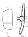
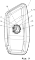
- FIG. 1 An indirect rear view system is provided with the reference number 1. It has a support element 2 for fastening at least one reflection element 3. There are two reflection elements 3, namely an upper mirror glass 4 and a lower mirror glass 5.
- the first axis of rotation is provided with the reference number 25, the second axis of rotation with the reference number 26 and the third axis of rotation with the reference number 27.
- an adjustment element 6 is present in the middle of the support element 2.
- the adjustment element 6 has a spherical connection area 7.
- the spherical connection area 7 has counter contact areas 8, which correspond to a first contact area 9 and a second contact area 10 of a coupling area 11.
- the coupling area 11 is present in the middle/central of a transition area 12 of the support element 2.
- the transition area 12 is that area of a transition at which a main body 13 merges into the coupling area 11.
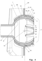
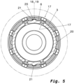
- connection area 7 has at least one flattening 16 between the axially separated counter-contact areas 8. Both the coupling area 11 and the connection area 7 can be designed to be elastic, in particular have slots 17, as shown in the Fig. 3 are also shown.
- index geometry 18 In the Fig. 4 the index geometry 18 according to the invention is shown larger.
- the index geometry 18 represents anti-twisting means 19. In particular, it is composed of components that implement a tongue and groove principle.
- the imaginary separation surface is in the Fig. 4 provided with the reference number 24.
- the coupling region 11 has a groove / channel / groove 20 that does not extend completely through the material of the coupling region 11. It also extends only over a partial segment of the coupling region 11, but at least from an open end of the adjustment element 6 facing the reflection element 3.
- the index geometry 18 also has a projection / rib / elevation 21 that extends radially outward from the connection region 7 in the direction of the coupling region 11. The projection / rib / elevation 21 engages into the groove / channel / groove with as little play as possible, ideally even completely free of play.
- the groove / channel / groove 20 has a polygonal / trapezoidal / parallelogram-like cross-section.
- the projection / rib / elevation 21 itself has a truncated cone-like outer contour with an opening angle of approx. 45°, 30°, 20°, 15° ⁇ 2.5°.
- the support element 2 is in a first basic position relative to the adjustment element 6 and in the Figure 6 in a second basic position.
- the first operating state is present in both the first basic position and the second basic position.
- the projection 21 jumps out of the groove 20 because a tab of the adjusting element 6 springs inwards and/or a tab of the supporting element 2 springs outwards.
- the second operating state is now present.
- the necessary overtorque is preset by the inclination of the outer contour of the projection/rib/elevation 21 and the restoring properties of the support element 3 and/or the adjustment element 6 in the area of the index geometry 18.
- the restoring properties of both the support element 2 and the adjustment element 6, and the opening angle of the truncated cone-shaped projection 21, are therefore coordinated with one another in such a way that they ensure linear contact between the support element 2 and the projection 21 of the adjustment element 6; such a choice is made specifically so that when the overtorque is exceeded (above the limit torque), the projection / rib / elevation 21 is allowed to break out of the groove / channel / groove 20 and a displacement of the support element 2 by, for example, 30°, 60° or, as shown here, 90° is possible.
- connection system 22 made possible by this is in the Figs. 7 and 8 used to create a connection to the motor vehicle.
- the connection system 22 also has a pipe 23.
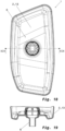
- FIG. 9 A further embodiment is shown in which the support element 2 is designed to be closed with a groove horizontally and vertically.
- the adjustment element 6 is designed to be slotted with a projection and is in particular self-resilient or provided with an optional spring element.
- the spring element is inserted internally from above into the supporting element 2.
- the support element 2 is designed like a shell with a projection on one side.
- the shell-like adjustment element 6 is provided with a horizontal and vertical groove.
- FIG. 16 and 17 A further embodiment is visualized in which the support element 2 is closed and is provided with a horizontal and vertical groove (each).
- the adjustment element 6 is slotted, designed with a projection and in particular self-springing or provided with an optional spring element.
- the spring element is arranged inside.
- joint contact area is inserted into the supporting element 2 from above, offset on one side, into the edge area of the counter-contact area 8.
- FIG. 18 and 19 A further embodiment is visualized in which the support element 2 is closed, namely with a groove (horizontal and vertical).
- the adjustment element 6 is slotted with a projection, ergo self-springing or with an optional spring element.
- the spring element is arranged inside.
- the joint contact area is offset on one side into the edge area of the counter contact area 8 and inserted from above into the supporting element 2.
- FIG. 20 and 21 A further embodiment is visualized in which the support element 2 is closed, namely with a groove (horizontal and vertical).
- the adjustment element 6 is slotted with a projection, ergo self-springing or with an optional spring element.
- the spring element is arranged inside.
- the joint contact area is offset on one side into the edge area of the counter contact area 8 and inserted from below into the supporting element 2.
- FIG. 20 and 21 A further embodiment is visualized in which the support element 2 is closed, with a projection.
- the adjustment element 6 is slotted with a groove (horizontal and vertical), self-springing or provided with an optional spring element.
- the spring element is inserted into the support element from above. This means that the arrangement of "projection and groove” is reversed in contrast to all other designs of the Figures 9 to 21 before.
Landscapes
- Engineering & Computer Science (AREA)
- Mechanical Engineering (AREA)
- General Engineering & Computer Science (AREA)
- Multimedia (AREA)
- Physics & Mathematics (AREA)
- General Physics & Mathematics (AREA)
- Optics & Photonics (AREA)
- Pivots And Pivotal Connections (AREA)
- Rear-View Mirror Devices That Are Mounted On The Exterior Of The Vehicle (AREA)
- Fittings On The Vehicle Exterior For Carrying Loads, And Devices For Holding Or Mounting Articles (AREA)
Description
- Die Erfindung betrifft ein indirektes Rücksichtsystem für ein Kraftfahrzeug, wie ein Nutzfahrzeug, eine Agrar- / Baumaschine, bspw. einen Traktor, oder etwa einen Lkw, einen Bus und/oder einen Transporter, mit einem Tragelement zum Befestigen wenigstens eines Reflexionselementes, wie einem Spiegelglas, wobei das Tragelement einen Koppelbereich zum lageveränderbaren Befestigen / Anbringen an einem seinerseits fahrzeuganbindbaren oder fahrzeugangebundenen Verstellelement besitzt, wobei der Koppelbereich einen Gegenkontaktbereich des Verstellelementes kontaktiert, wobei ferner am Tragelement und am Verstellelement ineinandergreifende Verdrehstopmittel vorhanden sind, etwa nach dem Nut- und -Feder-Prinzip.
- Aus dem Stand der Technik sind verschiedene Verstelleinheiten bekannt. So geht auf die Anmelderin das deutsche Patent
DE 101 63 318 C1 zurück. Dort ist eine Gelenkanordnung geschützt, nämlich eine Gelenkvorrichtung zur Anordnung von zwei Bauteilen im Winkel zueinander, insbesondere für Rückblickspiegel mit verstellbarer Spiegelscheibe, mit einem ersten Gelenkbauteil mit einer Kugelpfanne, einem zweiten Gelenkbauteil, das einen im wesentlichen kugelabschnittsförmigen Vorsprung aufweist, der in die Kugelpfanne eingepasst ist, einem Gleitteil, und einer Verbindungseinrichtung zum Herstellen einer Klemmverbindung zwischen erstem Gelenkbauteil, Gleitteil und zweitem Gelenkbauteil, wobei die einander zugewandten Seiten von Kugelpfanne, Gleitteil und Vorsprung jeweils eine konvexe Strukturierung und eine hierzu komplementär ausgebildete konkave Strukturierung aufweisen, wobei durch die Strukturierungen eine erste und eine zweite Drehachse zwischen Gleitteil, Kugelpfanne und Vorsprung festgelegt wird. Als Besonders ist herausgestellt, dass die konkave Strukturierung zumindest in entlastetem Zustand stärker gekrümmt ist als die konvexe Strukturierung. - Auf die Anmelderin geht auch das Europäische Patent
EP 3 335 938 B1 zurück. In diesem Patent ist eine Kugelgelenkvorrichtung zur verstellbaren Anordnung von einem ersten und einem zweiten Gelenkbauteil um einen Drehpunkt geschützt. Dabei besitzt die patentierte Kugelgelenkvorrichtung ein Kugelflächenelement, an dem ersten Gelenkbauteil mit einer Außenseite, die Teil einer Kugelfläche ist und einen ersten Krümmungsradius mit einem ersten Mittelpunkt aufweist. Eine Eingriffseinrichtung an dem zweiten Gelenkbauteil, die das Kugelflächenelement mit einer ersten Kontaktfläche kontaktiert, ist ebenfalls vorhanden. Auch weist jene Vorrichtung eine innerhalb des Kugelflächenelementes angeordnete, konkave kugelkappenförmige Aufnahme an dem ersten oder zweiten Gelenkbauteil auf, die einen zweiten Krümmungsradius mit einem zweiten Mittelpunkt besitzt. Das zweite oder erste Gelenkbauteil weist eine konkave Kugelkappe auf. Das zweite oder erste Gelenkbauteil weist eine konvexe Kugelkappe auf, die sich mit einer zweiten Kontaktfläche in der kugelkappenförmigen Aufnahme abstützt. Dabei ist der erste Krümmungsradius größer als der zweite Krümmungsradius. Die Einsatzeinrichtung übergreift das Kugelflächenelement und die beiden Gelenkbauteile nach Art einer Druckknopfverbindung miteinander. Als Besonders ist in jenem älteren Patent unter Schutz gestellt, dass das Kugelflächenelement abschnittsweise kugelringförmig ausgebildet ist, und dass das Kugelflächenelement mehrere über den Umfang verteilte kugelringförmige Abschnitte aufweist. - Weiterer Stand der Technik der dem Oberbegriff des unabhängigen Anspruchs 1 entspricht, ist aus der
JP 2018 - 154 287 A US 5 755 526 A bekannt. - Die
JP 2018 - 154 287 A - Die
US 5 755 526 A offenbart ein Kugelgelenk umfassend eine Pfanne mit einer Kammer. Ein Kugelzapfen umfasst ein Kugelende. Das Kugelende ist relativ zu der Pfanne in einer ersten Richtung in die Kammer in der Pfanne beweglich. Die Pfanne hat erste Abschnitte, die mit dem Kugelende in Eingriff gebracht werden können, um die Drehung des Kugelendes um eine erste Achse während der Bewegung des Kugelendes in die Kammer zu blockieren. Ein elastischer Halter wird während der Bewegung des Kugelkopfes in die Kammer ausgelenkt. Wenn sich das Kugelende in der Kammer befindet, richtet sich die Halterung auf, um das Kugelende in eine Betriebsposition in der Kammer zu drehen. Die Pfanne hat zweite Abschnitte, die mit dem Kugelkopf in Eingriff gebracht werden können, um die Bewegung des Kugelkopfes aus der Kammer zu blockieren, wenn sich der Kugelkopf in der Betriebsposition befindet. Der Eingriff des Halters in eine Halteröffnung in der Pfanne blockiert die Drehung des Kugelendes aus der Betriebsposition. - Es ist die Aufgabe der vorliegenden Erfindung, die aus dem Stand der Technik bekannten Nachteile zu mildern oder bestenfalls abzustellen.
- Diese Aufgabe wird erfindungsgemäß dadurch gelöst, dass die Verdrehstopmittel eine Indexgeometrie ausbilden, die in einem ersten Betriebszustand eine Verstellung / ein Verschwenken des Tragelementes relativ zum Verstellelement um zwei quer zueinander, vorzugsweise orthogonal zueinander, stehende Drehachsen zulässt und in einem zweiten Betriebszustand eine Grundpositionsänderung / eine Verstellung / ein Verschwenken des Tragelementes relativ zum Verstellelement um eine dritte Drehachse zulässt, die quer zu den beiden anderen Drehachsen, vorzugsweise orthogonal zu diesen, ausgerichtet ist. Es gilt zu beachten, dass in allen Betriebszuständen, auch in diesem wenigstens zweiten Betriebszustand, eine "normale" Verstellung um die Vertikal-/Hochachse und eine erste Horizontal-/Querachse auch möglich bleibt, eben um eine Links-/Rechtsverstellung und Auf-/Abverstellung des Spiegels zu erreichen.
- Unter Verdrehstopmittel werden solche Mittel verstanden, die in zumindest einem bestimmten Betriebszustand, insbesondere dem ersten Betriebszustand, eine Verdrehung des Tragelementes relativ zum Verdrehelement um eine bestimmte Drehachse verunmöglichen, wobei eine Verdrehung / Verschwenkung um zwei weitere dazu orthogonale Achsen ermöglicht bleibt.
- Liegt ein Überdrehmoment oberhalb eines vorbestimmten Grenzdrehmomentes vor, kann eine erste Grundposition verlassen werden und nach einer Gleitbewegung des Tragelements relativ zum Verstellement eine zweite Grundposition eingenommen werden. Dort findet vorzugsweise ein Einrasten bspw. als Einschnappen statt.
- In beiden Grundpositionen sind nur "normale" Verstellungen um die Hochachse und eine der beiden Querachsen möglich, eben um eine Links-/Rechtsverstellung und Auf-/Abverstellung des Spiegels zu erreichen.
- In den Grundpositionen, von denen es auch mehr als zwei geben kann, verunmöglichen die Verdrehstopmittel ein Verschwenken um eine weitere Achse, d.h. um eine zweite Horizontal-/Querachse, die sowohl zur Vertikal- /Hochachse als auch zur ersten Horizontal-/Querachse orthogonal ausgerichtet ist.
- Gerade für Spiegelsysteme, die an vielen verschiedenen Fahrzeugen verbaut werden, zeigt die Anzahl an geometrisch notwendigen Varianten, dass verschiedene Anbindungsgegebenheiten vorhanden sind. Dies kann z. B. bedeuten, dass eine Tragstruktur horizontal (auch links / rechts) auf einen Spiegelkopf angebunden werden muss und bei anderen Fahrzeugen eine vertikale (oben / unten) Anbindung bevorzugt ist. Dadurch entsteht eine Vielzahl von Varianten, die bereitgestellt werden müssen. Durch die Erfindung wird dies nun einfach ermöglicht. Es wird insbesondere ein indirektes Sichtsystem für ein Fahrzeug bereitgestellt, welches wenig geometrische Varianten aufweist und viele Anbindungen an verschiedenste Fahrzeuge oder Fahrzeugvarianten realisiert. Während üblicherweise Kugelverstellungen eingesetzt sind, die nach Art einer Nut-Feder-Verbindung verhindern, dass ein Spiegelkopf sich beim Verstellen (normales Einstellen des Sichtfeldes durch den Fahrer) um seine (meist annähernd horizontale) Kugelmittelachse verdreht, wird nun eine bedarfsgerechtere Lösung präsentiert. Die Nut-Feder-Verbindung kann nun auch in unterschiedlich geometrischer Form ausgestaltet sein, bspw. trapezförmig oder wellenförmig.
- Mit anderen Worten betrifft die Erfindung ein indirektes Sichtsystem für ein Fahrzeug umfassend wenigstens ein Reflexionselement zur indirekten Sicht, einem Tragelement und einem Verstellelement, wobei das Tragelement das Reflexionselement aufnimmt, und wobei das Tragelement und das Verstellelement über kugelförmige Kontaktbereiche zueinander über einen Drehpunkt verschwenkbar sind, wobei das Besondere ist, dass über eine Indexgeometrie zwischen dem Verstellelement und dem Tragelement, z. B. nach Art einer Nut-Feder-Verbindung, radial um die Kugelmittelachse verschiedene Betriebspositionen zwischen dem Verstellelement und dem Tragelement vordefiniert / definiert werden können. Die Betriebspositionen können nach der Montage des Spiegelkopfes noch (frei) gewählt werden, da die Indexgeometrie elastisch ausgeführt ist.
- Vorteilhafte Ausführungsformen sind in den Unteransprüchen beansprucht und werden nachfolgend näher erläutert.
- So ist es bspw. von Vorteil, wenn das Tragelement und das Verstellelement von ihrer Geometrie, Materialstärke und Materialbeschaffenheit so aufeinander abgestimmt sind, dass bei Vorliegen eines Überdrehmoments, das größer als ein vorbestimmtes Grenzdrehmoment ist, der Übergang vom ersten Betriebszustand in den zweiten Betriebszustand freigegeben / erzwungen wird. Man könnte auch sagen, dass zum Erreichen einer wenigstens zweiten Betriebsposition ein Überdrehmoment erforderlich ist, das höher als das definierte Drehmoment zum Stabilhalten des Tragelements in der Indexgeometrie ist.
- Dabei ist es von Vorteil, wenn das Verstellelement einen balligen Anschlussbereich besitzt, der den Gegenkontaktbereich ausbildet. Eine Verstellbarkeit in unterschiedliche Richtungen um bspw. die drei Drehachsen, ist dadurch einfach umsetzbar.
- Dabei ist es besonders von Vorteil, wenn der ballige Anschlussbereich kugelabschnittsartige Abschnitte besitzt.
- Hierbei ist es von Vorteil, wenn wenigstens eine erste Betriebsposition über die Kugelmittelachse um z.B. 90°, 45°, 30° (horizontal / vertikal / diagonal) zu wenigstens einer zweiten Betriebsposition erreicht wird. Somit kann eine nahezu horizontal ausgerichtete oder vertikal ausgerichtete Tragstruktur angebunden werden. Beispielsweise kann ein horizontales oder vertikales Rohr einfach angeschlossen werden. Ein nahezu horizontaler oder vertikaler oder diagonaler Tragstrukturabgang ist dann darstellbar. Es kann auch jeder andere Winkel umgesetzt werden.
- Wenn der Kontaktbereich eine Schale ausbildet, die den balligen Anschlussbereich umgibt / beherbergt, so kann mit einfachen Mitteln ein Befestigungsprinzip nach Art eines Druckknopfes umgesetzt werden. Dies ist dem Montageablauf zuträglich und spart Zeit ein.
- In puncto des Überdrehmomentes sei noch ergänzt, dass es von Vorteil ist, wenn das Überdrehmoment bevorzugt wenigstens ca. 7,5%, ca. 10 % oder ca. 25 % höher ist, als das definierte Drehmoment zum Stabilhalten des Tragelementes. Hierdurch ist es auch möglich, einen Kollisionsschutz durch Dämpfung und Nachgiebigkeit der Indexgeometrie zu erlangen. Das Überdrehmoment ist ergo höher als das vordefinierte Grenzdrehmoment. Oberhalb des Grenzdrehmomentes findet beispielsweise eine Freigabe einer Schnappverbindung statt. Nach der durchgeführten Verstellung findet wieder ein selbständiges Halten in der Indexgeometrie statt.
- Vorteilhaft ist es auch, wenn die Indexgeometrie in Form einer Nut- und -Feder-Verbindung ausgeführt ist.
- Wenn dabei die Nut im Tragelement und die Feder im Verstellelement integriert ist, oder die Nut im Verstellelement und die Feder im Tragelement integriert ist, so lassen sich bedarfsgerechte Lösungen umsetzen.
- Dabei ist es auch von Vorteil, wenn die Indexgeometrie federnd ausgeführt ist bzw. wenigstens eines der beiden sie stellenden Bauteile.
- Wenn die federnde Ausführung mittels Schlitze in den kugelförmigen Kontaktbereichen ausgeführt wird, so stellen sich Vorteile im Dauerbetrieb aber auch schon während der Montage ein.
- Letztlich betrifft die Erfindung auch die Ausbildung des indirekten (Rück-)Sichtsystems nach Art eines Spiegelkopfes.
- Das indirekte (Rück-)Sichtsystem kann insbesondere ein Kopfversteller oder Glasversteller sein.
- Eine vorteilhafte Ausführungsform ist auch dadurch gekennzeichnet, dass das Tragelement und das Verstellelement gezielt so gestaltet sind, dass die Rückstelleigenschaften und das E-Modul der beiden Bauteile so auf die Kontur der ineinandergreifenden Indexgeometriebauteile abgestimmt sind, dass bei Vorliegen des Überdrehmoments der wenigstens zweite Betriebszustand zwangseingenommen wird. Bei Vorliegen des Überdrehmoments - oberhalb des vordefinierten Grenzdrehmoments - wird die bis dahin eingenommene Grundposition verlassen. Eine Bewegung zur zweiten Grundposition findet statt. Dort findet wieder ein Einrasten statt. Die für das selbständige Einrasten oder Einschnappen nötige Kraft kann durch die Rückstellkraft wenigstens eines der beiden die Indexgeometrie ausbildenden Bauteile aus elastischem Material gestellt werden.
- Insbesondere hat es sich dabei bewährt, ein erstes Indexgeometriebauteil als eine Rille / Rinne / Riefe, bspw. nach Art einer Nut- und -Feder-Konfiguration, auszugestalten und ein zweites Indexgeometriebauteil als einen Vorsprung / eine Rippe / eine Erhöhung, bspw. nach Art einer Feder einer Nut- und -Feder-Konfiguration, auszugestalten.
- Für eine Weiterbildung ist es von Vorteil, wenn die Rille / Rinne / Riefe am Tragelement, insbesondere auf seiner dem Verstellelement zugewandten (Innen-)Seite, vorhanden ist und der Vorsprung / die Rippe / die Erhöhung am Verstellelement, insbesondere auf seiner dem Tragelement zugewandten (Außen-)Seite, vorhanden ist bzw. vice versa.
- Um auch einen Überlastschutz vorzuhalten und ein Abklappen im Notfall zuzulassen, ist es von Vorteil, wenn das Grenzdrehmoment ca. 10 % oder ca. 20 % oder ca. 30 % oder besonders bevorzugt ca. 33 % größer ist, als das im ersten Betriebszustand auftretende (normale) Drehmoment, das zum Stabilhalten des Tragelementes zum Verstellelement benötigt ist. Hier ist ein gezieltes Ausrichten / Abstimmen der Innengeometrie bspw. der Rinne / Rille / Riefe von Vorteil.
- Ein präzises Verstellen ist dann darstellbar, wenn der Vorsprung spielfrei in die Rille / Rinne / Riefe eingreift bzw. in ihr gelagert ist. Allerdings ist ein Spiel von einigen wenigen 10tel Millimeter im Sinne einer Quasi-Spielfreiheit oder Nahezu-Spielfreiheit akzeptierbar. Diese Überlegungen sind insbesondere vor dem Hintergrund von Fertigungstoleranzen und einem Bauteilverzug zu berücksichtigen.
- Eine vorteilhafte Ausführungsform ist auch dadurch gekennzeichnet, dass der Vorsprung in einem Querschnitt orthogonal zur Längsachse der Rille / Rinne / Riefe eine angeschrägte Seite besitzt, die zum Eingehen eines Linienkontakts mit dem die Rille / Rinne / Riefe ausbildenden Material konturiert ist. Durch die angeschrägte Seite und die elastische Indexgeometrie generiert sich das Grenzdrehmoment bzw. wird dadurch vorbestimmt. Beim Verlassen der ersten Grundposition muss eine schiefe Ebene überwunden werden. Das Verhältnis der Schräge zur Anpresskraft (vorgegeben durch das Widerstandsmoment bspw. einer Lasche) legt das Grenzdrehmoment fest.
- Besonders bevorzugt ist es in diesem Zusammenhang, wenn der Vorsprung wenigsten im Wirkbereich, also dort, wo die beim und für das Verlassen der Grundposition notwendige Schräge vorhanden ist, eine Kegelkontur oder Kegelstumpfkontur oder kugelabschnittsartige Kontur oder sphärische / ellipsoide Kontur besitzt. Ein problemloses Verstellen in möglichst alle Raumrichtungen ist dann darstellbar. Der Wirkbereich kann nur in einem bestimmten Winkelbereich des Vorsprungs vorhanden sein und dann eben nur dort die besagte Schräge besitzen. In den anderen Winkelbereichen kann diese Schräge fehlen. Dort, wo die Schräge fehlt, ist kein Wirkbereich vorhanden. Mit anderen Worten ist wenigstens im Bereich jenes Winkelbereichs, in dem die Verstellung und ein "Heraushüpfen" erzwungen ist, eine "Wirkkontur" aufweisend die Schräge vorhanden. Aus Symmetriegründen und Fertigungsgründen kann die Schräge jedoch auch in jenen Winkelbereichen vorhanden sein, in denen kein Wirkbereich vorhanden ist.
- Dabei ist es von Vorteil, wenn die Rille / Rinne / Riefe eine Tiefe besitzt, die zwischen ca. 10 % bis ca. 45 % der Dicke des Koppelbereiches beträgt.
- Es hat sich bewährt, wenn die Indexgeometrie aus zwei Bauteilen zusammengesetzt ist, von denen wenigstens eines elastisch ausgebildet ist.
- Auch ist es von Vorteil, wenn der Koppelbereich bspw. etwa zentrums- / mittelpunktsnah des Tragelementes vorhanden ist und zum beispielsweise druckbeaufschlagenden - etwa kraftschlusseingehenden und/oder formschlusseingehenden - Kontaktieren mit dem balligen Anschlussbereich des Verstellelementes, etwa nach Art einer Druckknopfkonfiguration, ausgebildet ist.
- Vorteilhaft ist es auch, wenn der Koppelbereich einen ersten Kontaktbereich und einen dazu axial versetzten zweiten Kontaktbereich besitzt, wobei die Axialrichtung durch die Einsatzrichtung des Verstellelementes in das Tragelement oder eine Horizontalachse, vorzugsweise durch einen Drehpunkt, um den das Tragelement verschwenkbar ist, definiert ist.
- Wenn durch einen Bereich des Übergangs eines Hauptkörpers des Tragelementes in den Koppelbereich eine gedachte Trennfläche ebene verläuft, so kann auf weiterführende Konfigurationen zurückgegriffen werden. Die Trennfläche kann plan, ergo als Trennebene ausgebildet sein. Die Trennfläche verläuft durch den Bereich des Übergangs vom Hauptkörper des Tragelements in den Koppelbereich des Tragelements beiderseits des Drehpunktes. Unterschiedliche räumliche Konfigurationen der Trennfläche sind möglich. Beispielsweise sind Freiflächengestaltungen umsetzbar. Insbesondere kann die Trennfläche plan, also eben, ausgebildet sein und formt in diesem Spezialfall dann eine Trennebene aus.
- Eine dieser Konfigurationen stellt sich bspw. ein, wenn der erste Kontaktbereich einerseits der gedachten Trennfläche verläuft und der zweite Kontaktbereich andererseits der gedachten Trennfläche verläuft.
- So ist es ferner von Vorteil, wenn der erste Kontaktbereich als ein innerer Kontaktbereich ausgebildet ist, der im Inneren eines durch das Tragelement und dem Reflexionselement definierten Raum liegt und der zweite Kontaktbereich als ein äußerer Kontaktbereich ausgebildet ist. Ein Aufteilen des Kraftflusses vom Bereich des Übergangs des Hauptkörpers des Tragelementes in den Koppelbereich des Tragelementes in zwei unterschiedliche, vorzugsweise entgegengesetzte Richtungen, ist dann die Folge. Der Gesamtkraftfluss wird nun möglichst gleichmäßig verteilt, was einen Bruch des Tragelementes vermeidet und ein besseres Halten des Tragelementes an dem balligen Anschlussbereich des Verstellelementes hervorruft.
- Dadurch, dass der erste Kontaktbereich im Inneren des vom Tragelement und dem Reflexionselement definierten Raumes liegt, ist dieser Kontaktbereich auch vor Schmutz und Verunreinigung geschützt, was einen langfristigen guten sowie reibungsarmen Gebrauch ermöglicht und die Verstellbarkeit auch bei schwierigen Rahmenbedingungen sicherstellt.
- Wenn der erste Kontaktbereich und der zweite Kontaktbereich jeweils kugelabschnittsartige Innenkontursegmente besitzen, so ist ein Anpassen eines oder beider Kontaktbereiche auf den balligen Anschlussbereich zum Sicherstellen einer guten Verstellbarkeit besonders effizient möglich.
- Eine vorteilhafte Ausführungsform ist auch dadurch gekennzeichnet, dass die Innenseite des Koppelbereichs (des Tragelementes) die Außenseite des Anschlussbereiches (des Verstellelementes), so aufeinander abgestimmt sind, dass durch beide Bauteile ein Drehpunkt definiert ist, um den das Tragelement relativ zum Verstellelement verschwenkbar ist. Im Einsatz des Rücksichtsystems kann dann vom Nutzer eine bedarfsgerechte Winkelposition der beiden Bauteile zueinander leicht eingestellt werden.
- Es ist von Vorteil, wenn der Anschlussbereich kugelabschnittsartige Gegenkontaktbereiche besitzt. Das Verschwenken / Schwenken wird dadurch erleichtert.
- Dabei ist es ferner vorteilhaft, wenn die Gegenkontaktbereiche an die mit ihnen in Kontakt stehende Kontaktbereiche, insbesondere bezüglich ihrer Kontur, angepasst sind. Dadurch lassen sich bspw. auch von einer sphärischen Geometrie abweichende Teilbereiche integrieren oder auch ellipsoide Teilbereiche einsetzen.
- Wenn die Gegenkontaktbereiche über Abplattungsbereiche bzw. einen Abplattungsbereich verbunden sind, so wird eine Montageerleichterung einerseits und eine Federelemententlastung andererseits sowie eine Vermeidung von Überbestimmung(en) an den Auflageflächen erreicht.
- Für die Serienfertigung hat es sich als vorteilhaft herausgestellt, wenn das Tragelement als Rückwand und/oder das Verstellelement als (Dreh-)Zapfen, vorzugsweise aus Kunststoff etwa Polyamid, bspw. als integrales / einstückiges, einmaterialiges Bauteil ausgebildet ist.
- Es ist zweckmäßig, wenn das Verstellelement am Tragelement befestigt ist, bspw. über einen Form- und/oder Kraftschluss.
- Ein besonders guter Sitz der beiden Bauteile aneinander wird gewährleistet, wenn das Verstellelement eine Aufnahme zum Anschluss eines fahrzeugfesten Halters / Teleskopstangenhalters, Stabes oder (Teleskop-)Rohres besitzt oder entsprechend selbst ausgebildet ist.
- Darüber hinaus hat es sich bewährt, wenn die Aufnahme als Sackloch ausgebildet ist, dessen Boden zur Verdrehverunmöglichung stufig ausgeformt ist.
- Die Anbringungsmöglichkeiten lassen sich vielseitig gestalten, wenn das Verstellelement einen indirekten oder direkten Anbindebereich zum Fahrzeug besitzt, der bspw. das Sackloch aufweist.
- Das Gewicht lässt sich optimieren, wenn die beiden Kontaktbereiche gemeinsam eine kugelabschnittsartige Schale ausbilden, die im Bereich des Übergangs in den Hauptkörper münden.
- Der Kompaktheit des Systems ist es zuträglich, wenn der Hauptkörper im Bereich des Übergangs in einen Winkel α von 15° bis 125° +/- 5° auf die Schale trifft, vorzugsweise 90° +/- 2,5°, wobei der Winkel α zwischen einerseits einer gedachten Gerade durch den Bereich des Übergangs vom Hauptkörper in den Koppelbereich und andererseits einer in Axialrichtung verlaufenden, gedachten Gerade durch den (Kugel-)Mittelpunkt des Anschlussbereichs und/oder den Drehpunkt aufgespannt ist.
- Wenn der Hauptkörper in Richtung des Drehpunktes eine gedachte Peillinie vorgibt, die eine theoretische Kugel um den Drehpunkt mit einem Durchmesser von 50 mm, 60 mm oder 70 mm schneidet, so ist der Kraftverlauf in Richtung des Zentrums des Anschlussbereichs besonders gut.
- Es hat sich auch bewährt, wenn am Tragelement ein Glaselement angebunden ist, etwa mittels eines Form- und/oder Kraftschlusses, insbesondere bspw. mittels einer Clips-Lösung und das Glaselement als Spiegelglas ausgebildet ist.
- Eine vorteilhafte Ausführungsform ist auch dadurch gekennzeichnet, dass an (wenigstens / nur) einem der beiden Kontaktbereiche, vorzugsweise dem ersten Kontaktbereich, oder beiden Kontaktbereichen im montierten Zustand eine Federkraft anliegt, die den Koppelbereich zumindest in jeder den Kontaktbereich in Richtung des Koppelbereichs inneren, vorzugsweise in Richtung des Drehpunktes, drängt. Ein Selbstfixieren nach einer Verstellung wird dadurch erleichtert und eine Variabilität zum Erreichen einer guten Wiedergabe des rückwärtigen Sichtbereiches des Fahrers ist die Folge.
- Es ist zweckmäßig, wenn die Federkraft durch ein Federelement, wie einen Ring oder eine Klammer gestellt ist. Das Federelement kann eine oder mehrere Windungen besitzen.
- Durch ein solch separates Federelement kann die Federkraft gezielt eingestellt werden. Auch hat es sich bewährt, wenn der Ring einen geschlossenen oder offenen, bspw. geschlitzten, Querschnitt besitzt. Die Montage wird dadurch insbesondere im zweiten Fall verbessert und die Dauerfestigkeit / Dauerbelastbarkeit insbesondere im ersten Fall.
- Um auch eine lange Lebensdauer mit unveränderten technischen Rahmenbedingungen sicherzustellen, ist es von Vorteil, wenn das Federelement aus einem metallischen Baustoff, etwa aufweisend eine Eisenlegierung, bspw. nach Art von Federstahl, hergestellt / geschaffen ist.
- Um einen einfachen modularen Aufbau zu gewährleisten, ist es von Vorteil, wenn das Federelement als Druckfeder ausgebildet ist, die an der Außenseite des ersten Kontaktbereiches oder des zweiten Kontaktbereiches anliegt. Ein nachträgliches Aufbringen wird dadurch auch erleichtert.
- Für die Verbindung der Einzelbauteile zueinander, insbesondere um ein Verlieren der Bauteile zu verunmöglichen, ist es von Vorteil, wenn auf der Außenseite des (jeweiligen) Kontaktbereiches eine Vertiefung, etwa nach Art einer Mulde, Rille oder Rinne, ausgebildet ist, in der das Federelement im montierten Zustand ruht / sitzt / angeordnet ist.
- Um einen Gleitbereich zwischen dem Tragelement und dem Verstellelement dauerhaft sauber / frei von Verunreinigung zu halten, ist es von Vorteil, wenn zwischen einem der Kontaktbereiche und dem ihm zugeordneten Gegenkontaktbereich, vorzugsweise dem ersten Kontaktbereich und dem ihm zugeordneten Gegenkontaktbereich, mittels dem Tragelement und/oder dem Verstellelement eine Dichtfunktion realisiert ist, bspw. über eine angeformte Dichtlippe an einem oder beiden Bauteile, und/oder ein zusätzliches Dichtelement zwischen dem Tragelement und dem Verstellelement eingebaut / zwischengeschalten ist.
- Für die Montage ist es von Vorteil, wenn der Koppelbereich ganz oder wenigstens abschnittsweise / teilweise elastisch ausgebildet ist.
- Auch ist es von Vorteil, wenn (vorrangig) nur im ersten Kontaktbereich und/oder (nachrangig) nur im zweiten Kontaktbereich Elastizität hervorrufende Geometrieveränderungen, wie Verdünnungen, Schlitze, Freistellungen, Nute, Wellformen und/oder ähnliche Gestaltungen vorhanden sind.
- Um unterschiedliche Betriebspositionen vorgeben zu können, ist es von Vorteil, wenn der Koppelbereich und der Anschlussbereich zum Ausbilden einer Indexgeometrie ausgebildet sind, mittels der bestimmte vordefinierte Relativpositionen zwischen dem Tragelement und dem Verstellelement einnehmbar sind.
- Dabei ist es von Vorteil, wenn die Indexgeometrie nach Art eines Nut-und-Feder-Ineinandergreifens ausgeformt ist.
- Bewährt hat es sich dabei, wenn der Koppelbereich auf seiner Innenseite wenigstens eine Nut / Rinne / Rille oder eine Vielzahl derer besitzt und wobei in wenigstens eine oder mehrere derer (je) als Vorsprung auf der Außenseite des Verstellelementes eingreift oder als Alternative / Ergänzung das Verstellelement auf seiner Außenseite wenigstens eine Nut / Rinne / Rille oder eine Vielzahl derer besitzt und wobei in wenigstens eine Nut / Rinne / Rille oder mehrere (je) ein Vorsprung auf der Innenseite des Koppelbereiches des Tragelementes eingreift.
- Wenn die Nut / Rinne / Rille und/oder der Vorsprung im Querschnitt eine V-, U-, dachförmige oder polygonförmige Kontur besitzt und/oder beide (nahezu) spielfrei zusammenpassend ausgeformt sind, so ist ein wackelfreies Anpassen des Verstellelementes an das Tragelement und vice versa möglich.
- Um die Verstellung auch stufenlos gestalten zu können, ist es von Vorteil, wenn der Vorsprung in der Nut / Rinne / Rille (kontinuierlich / diskontinuierlich) verschieblich / gleitbar eingebaut / eingesetzt ist.
- Darüber hinaus hat es sich auch bewährt, wenn auf gegenüberliegenden Außenseiten des Verstellelementes vom Drehpunkt aus gesehen Nuten / Rinnen / Rillen vorhanden sind, von denen zwei mit je einem Vorsprung des Verstellelementes zumindest in einem Abschnitt ausgefüllt sind und wenigstens zwei oder ein ganzzahliges Vielfaches an Nuten / Rillen / Rinnen vorsprungsfrei bleiben.
- Wenn die Nuten / Rinnen / Rillen gleichmäßig über den Innenumfang des Koppelbereiches verteilt sind, z. B. alle 90°, 45°, 22,5°, 12,25° oder 6,125°, so lassen sich bedarfsgerechte Verstellungen vorhalten.
- Die Erfindung betrifft letztlich eine solche Ausgestaltung, bei der ein Spiegelkopf ausgebildet ist und/oder ein Kopfversteller oder ein Glasversteller umfasst ist.
- Wenn der innere Kontaktbereich und/oder der äußere Kontaktbereich radial geschlossen ist und vorzugsweise elastische Teilbereiche besitzt, so wird bei Ausschluss von Verschmutzungsmöglichkeiten bzw. einem Vorhalten von einem Schmutzschutz eine einfache Montage ermöglicht.
- Die Erfindung betrifft letztlich auch ein Montageverfahren zum Koppeln eines Tragelementes des indirekten Rücksichtsystems der erfindungsgemäßen Art an dem Verstellelement, wobei das Tragelement aus Richtung des Reflexionselementes in Richtung des Verstellelementes beispielsweise über einen dort ausgebildeten Gegenkontaktbereich bewegt wird / erfolgt. Ein Aufschnappen ist die Folge.
- Eine Weiterbildung wird darin gesehen, dass der Koppelbereich ausbildend den zweiten Kontaktbereich und/oder den ersten Kontaktbereich beim Aufschieben auf das Verstellelement erst aufgeweitet wird und danach elastisch rückfedert.
- Dabei ist es von Vorteil, wenn der Koppelbereich auf eine sphärische Verdickung / auf den balligen Anschlussbereich des Verstellelementes aufgeclipst wird.
- Mit anderen Worten betrifft die Erfindung ein indirektes Sichtsystem für ein Fahrzeug, wobei der Winkel α zwischen einer horizontalen Kugelmittelachse und einem Schenkel des Kugelmittelpunkts zum Auftreffpunkt der Rückwand auf den Kontaktbereich von minimal 15° bis maximal 125° beträgt.
- Eine Weiterbildung kann auch dadurch in Worte gefasst werden, dass das Verstellelement mit dem Anbindebereich zum Fahrzeug und in Wirkflächen zum Tragelement einstückig ausgebildet ist.
- Darüber hinaus kann die Richtung der Rückwand im Bereich des Kontaktbereiches derart gestaltet sein, dass diese in einer theoretischen Verlängerung zum Kugelmittelpunkt hin eine theoretische Kugel von einem Durchmesser von 60 mm durchschneidet.
- Als vorteilhaft wird auch gesehen, dass die Montage des Verstellelementes zum Tragelement aus Richtung des Reflexionselementes von innen nach außen erfolgt und der äußere Kontaktbereich und der innere Kontaktbereich radial geschlossen sind oder der äußere Kontaktbereich radial geschlossen ist und der innere Kontaktbereich elastische Teilbereiche aufweist. Hier bieten sich Schlitze, Freistellungen, Nuten und Wellformen an. Eine Segmentierung bzw. ein Umsetzen eines Druckknopfprinzips lässt sich dadurch einfacher bewerkstelligen. Die Schlitze bewirken dabei eine elastische Federwirkung des Kontaktbereiches.
- Mit anderen Worten betrifft die Erfindung auch eine Montage des Verstellelementes zum Tragelement aus Richtung des Reflexionselementes von innen nach außen, wobei der äußere und innere Kontaktbereich des Tragelementes radial geschlossen ist und das Verstellelement elastische Teilbereiche aufweist.
- Wenn an den äußeren oder inneren Kontaktbereichen des Tragelementes mittels eines Federelementes ein Druck auf die Kontaktbereiche des Verstellelementes aufgebracht wird, so wird mittels der Feder die Reibung erhöht, damit es eine höhere Verstellkraft für die Verstellung erzwingt.
- Es ist von Vorteil, wenn an den äußeren oder inneren Kontaktbereichen des Verstellelementes mittels eines Federelements ein Druck auf die Kontaktbereiche des Tragelementes aufgebracht wird.
- Dabei ist es von Vorteil, wenn das Federelement eine Metallfederklammer oder eine offene oder geschlossene Metallringfeder mit einer oder mehreren Windungen ist.
- Auch ist es von Vorteil, wenn im äußeren Kontaktbereich des Tragelementes und dem äußeren Kontaktbereich des Verstellelementes eine Dichtfunktion integriert ist. Es sind angeformte Dichtlippen am Tragelement genauso denkbar, wie zusätzliche Dichtlippen mit einem zweiten Werkstoff, die angeformt sind. Auch sind zusätzliche Dichtelemente, welche montiert werden, denkbar.
- Wenn das indirekte Sichtsystem mittels eines Rohres oder das Verstellelement am Fahrzeug direkt oder indirekt montiert ist und das Verstellelement einstückig oder mehrteilig ausgeführt ist, um das Rohr zu befestigen, so lassen sich weitere Alternativen realisieren. Dabei kann bei der direkten Montage ein Rohr am Fahrzeug montiert werden oder bei der indirekten Montage ein zusätzliches Halteelement, wie etwa ein Teleskopstangenhalter verwendet werden.
- Es ist von Vorteil, wenn das Rohr im Verstellelement über Formschluss, also entsprechende geometrische Formen, eindeutig definiert, positioniert und fixiert ist. Dies hat den Vorteil, dass durch die eindeutige Positionierung des indirekten Sichtsystems ein gefordertes Sichtfeld, z. B. um Kundenanforderungen zu erfüllen oder gesetzliche Sichtfelder - wie bswp. die Normen UN/ECE-R46 oder ISO 5721-2 oder ISO 5006 fordern - immer eingehalten werden. Zudem ist der Spiegelkopf mit dem Verstellelement verliersicher angebracht und kann nicht "abfallen", falls der Kraftschluss verloren geht oder sich verringert.
- Es ist auch von Vorteil, wenn das indirekte Sichtsystem über das Verstellelement am Fahrzeug direkt, bspw. über ein Verstellelement, was am Fahrzeug montiert ist, angebracht ist und das Verstellelement einstückig oder mehrteilig ausgeführt ist.
- Auch ist es von Vorteil, wenn über eine Indexgeometrie zwischen dem Verstellelement und dem Tragelement, z. B. nach Art von Nut und Feder, radial um die horizontale Kugelmittelachse verschiedene Betriebspositionen zwischen dem Verstellelement und dem Tragelement einstellbar sind. Die Betriebspositionen können nach der Montage des Spiegelkopfes noch gewählt werden, da die Indexgeometrie elastisch ausgeführt ist. Hierdurch ist es auch möglich einen Kollisionsschutz durch Dämpfung und Nachgiebigkeit der Indexgeometrie zu erlangen.
- Wie erläutert, ist es von Vorteil, wenn das indirekte Sichtsystem ein Spiegelkopf ist und/oder das indirekte Sichtsystem ein Kopfversteller oder Glasversteller ist.
- Es zeigen sich bei der erfindungsgemäßen Lösung zahlreiche Vorteile. So stellt sich ein optimierter Kraftfluss vom Tragelement in das Verstellelement ein, da die Krafteinleitung zwischen dem inneren und äußeren Kontaktbereich stattfindet und so die Kraft besser aus dem Tragelement in das Verstellelement übertragen wird. Auch reduziert sich die Anzahl der Bauteile, da die Funktion und die geometrische Gestalt integriert sind. Die Kontaktbereiche des Tragelementes und des Verstellelements umschlingen sich und es ist kein zusätzliches Gleitelement oder Fügeelement erforderlich. Es stellt sich eine vereinfachte Montage ein, da weniger Bauteile benötigt werden. Hierdurch werden auch die Kosten reduziert. Der Verstellmechanismus muss in einer Ausführungsform nur noch "verschnappt" werden, und es ist kein Fügeelement wie eine Schraube oder ein Riegelbolzen mehr erforderlich.
- Durch die Indexgeometrie nach Art einer Nut-und-Feder-Kombination, wird bei Aufbringen eines größeren Drehmoments eine Verstellung ermöglicht, etwa um von einer hochformatigen auf eine querformatige Anbringung zu wechseln.
- Ein weiterer positiver Aspekt bezieht sich auf die Führung eines Elektrobabels, mit dem ein Anschluss elektrischer Module, wie Heizfolien bspw. auf der Spiegelrückseite (d.h. im Inneren des durch das Glaselement und das Tragelement begrenzten Raumes), Blindspot- und/oder Parkdistanz-Systeme, realisiert werden kann. Solche Elektrokabel / Versorgungsleitungen lassen sich dann durch das Innere des balligen Anschlussbereichs des Verstellelements bzw. der vom Verstellelement ausgebildeten Kugel führen.
- Durch die Lösung ist es gleichzeitig möglich, auch im Falle einer Kollision einen Schutz der Bauteile zu realisieren, da eine Verdrehung über das Drehmoment zum Stabilhalten des Tragelements ermöglicht ist. Auch nach der Montage des Spiegelkopfes ist eine Herstellung von Varianten möglich, z. B. bei einem horizontalen oder gewünschten vertikalen Abgang einer Tragstruktur zum Fahrzeug hin. Hierdurch entsteht ein Kostenvorteil.
- Geometrische Spiegelköpfe können sowohl auf der linken als auch auf der rechten Seite eines Fahrzeugs verwendet werden, da sich die Anbindung um 180° über zwei Betriebsstellungen verdrehen lässt. Dadurch werden Varianten reduziert, was einen geringeren Aufwand in Produktion, Logistik und Lagerhaltung sowohl beim Hersteller als auch im Verkauf (insbesondere dem Handel und den Fahrzeugherstellern) bringt.
- Die Erfindung wird nachfolgend mit Hilfe mehrerer Ausführungsformen mittels einer Zeichnung näher erläutert. Es zeigen:
- Fig. 1
- eine isometrische Ansicht auf ein indirektes Rücksichtsystem gemäß einer ersten Ausführungsform der Erfindung für ein Kfz, nämlich einen Lkw, einen Bus bzw. einen Transporter,
- Fig. 2
- einen Längsschnitt entlang der Linie II aus
Fig. 1 durch das Rücksichtsystem der ersten Ausführungsform, - Fig. 3
- eine Rückansicht auf das Rücksichtsystem der
Fign. 1 und 2 , - Fig. 4
- eine Vergrößerung des Bereiches IV aus
Fig. 2 , - Fig. 5
- eine Ansicht auf den Bereich aus
Fig. 4 von hinten, ähnlich der Darstellungsform ausFig. 3 , - Fig. 6
- eine zweite Ausführungsform in einer zur
Fig. 5 vergleichbaren Darstellungsweise, - Fig. 7
- eine Anbindung des in beiden Ausführungsformen enthaltenen Verstellelementes an ein im Anschlussbereich vertikal verlaufendes Rohr,
- Fig. 8
- eine Anbindung der anderen Ausführungsform an ein im Anbindungsbereich horizontal ausgerichtetes Rohr, und
- Fig. 9 bis 23
- unterschiedliche Ausführungsformen in unterschiedlichen Ansichten und Schnitten / Detailansichten.
- Die Figuren sind lediglich schematischer Natur und dienen nur dem Verständnis der Erfindung. Die gleichen Elemente sind mit denselben Bezugszeichen versehen. Merkmale der einzelnen Ausführungsformen können untereinander ausgetauscht werden.
- In der
Fig. 1 ist ein indirektes Rücksichtsystem mit dem Bezugszeichen 1 versehen. Es besitzt ein Tragelement 2 zum Befestigen wenigstens eines Reflexionselementes 3. Es gibt zwei Reflexionselemente 3, nämlich ein oberes Spiegelglas 4 und ein unteres Spiegelglas 5. - In der
Fig. 4 ist die erste Drehachse mit dem Bezugszeichen 25, die zweite Drehachse mit dem Bezugszeichen 26 und die dritte Drehachse mit dem Bezugszeichen 27 versehen. - Schon in der
Fig. 2 ist zu erkennen, dass mittig des Tragelementes 2 ein Verstellelement 6 vorhanden ist. Das Verstellelement 6 besitzt einen balligen Anschlussbereich 7. Der ballige Anschlussbereich 7 weist Gegenkontaktbereiche 8 auf, die mit einem ersten Kontaktbereich 9 und einem zweiten Kontaktbereich 10 eines Koppelbereiches 11 korrespondieren. Der Koppelbereich 11 ist mittig / zentral eines Übergangsbereichs 12 des Tragelementes 2 vorhanden. Der Übergangsbereich 12 ist jener Bereich eines Übergangs, an dem ein Hauptkörper 13 in den Koppelbereich 11 übergeht. - Im ersten Kontaktbereich 9 ist eine Mulde 14 vorhanden, in die ein Federelement eingesetzt werden kann. Es gibt einen Drehpunkt 15, um den das Tragelement 2 drehbar ist. Der Anschlussbereich 7 besitzt wenigstens eine Abplattung 16 zwischen den voneinander axial getrennten Gegenkontaktbereichen 8. Sowohl der Koppelbereich 11, als auch der Anschlussbereich 7 kann elastisch ausgebildet sein, insbesondere Schlitze 17 besitzen, wie sie in der
Fig. 3 auch dargestellt sind. - In der
Fig. 4 ist die erfindungsgemäße Indexgeometrie 18 größer dargestellt. Die Indexgeometrie 18 stellt Verdrehstopmittel 19. Insbesondere setzt sie sich aus Bauteilen zusammen, die ein Nut- und -Feder-Prinzip realisieren. - Die gedachte Trennfläche ist in der
Fig. 4 mit dem Bezugszeichen 24 versehen. - Insbesondere weist bspw. der Koppelbereich 11 eine Rille / Rinne / Riefe 20 auf, die sich nicht vollständig durch das Material des Koppelbereiches 11 erstreckt. Sie erstreckt sich auch nur über ein Teilsegment des Koppelbereiches 11, zumindest aber von einem dem Reflexionselement 3 zugewandten offenen Ende des Verstellelementes 6. Die Indexgeometrie 18 weist auch einen Vorsprung / eine Rippe / eine Erhöhung 21 auf, der sich vom Anschlussbereich 7 radial nach außen in Richtung des Koppelbereiches 11 erstreckt. Der Vorsprung / die Rippe / die Erhöhung 21 greift möglichst spielfrei, im besten Fall sogar vollständig spielfrei, in die Rille / Rinne / Riefe ein.
- Wie auch in den
Fig. 5 und6 gut zu erkennen ist, in der zwei Ausführungsformen bzw. zwei unterschiedliche Positionen / Grundpositionen einer einzigen Ausführungsform dargestellt sind, weist die Rille / Rinne / Riefe 20 einen polygonförmigen / einen trapezförmigen / parallelogrammartigen Querschnitt auf. Der Vorsprung / die Rippe / die Erhöhung 21 selber hat eine kegelstumpfartige Außenkontur mit einem Öffnungswinkel von ca. 45°, 30°, 20°, 15° ±2,5°. - In der
Figur 5 ist das Tragelement 2 relativ zum Verstellelement 6 in einer ersten Grundposition und in derFigur 6 in einer zweiten Grundposition dargestellt. Sowohl in der ersten Grundposition, als auch in der zweiten Grundposition liegt der erste Betriebszustand vor. Eine Verdrehung nur um zwei zueinander orthogonal ausgerichtete Achsen, nämlich die Vertikalachse und eine erste Horizontalachse, bleibt dabei möglich. - Wird ein Überdrehmoment aufgebracht, springt der Vorsprung 21 aus der Rille 20, weil eine Lasche des Verstellelementes 6 nach innen federt und/oder eine Lasche des Tragelementes 2 nach außen federt. Nun liegt der zweite Betriebszustand vor.
- Während dieses zweiten Betriebszustandes wird das Tragelement 2 relativ zum Verstellelement 6 um eine weitere / zweite Horizontalachse verschwenkt. Dann vollzieht der in
Fig. 5 obere Vorsprung 21 eine 90° Drehung und rastet, so wie inFig. 6 zu sehen, in eine andere Rille 20 wieder ein. Erst dann ist die zweite Grundposition eingenommen und der erste Betriebszustand liegt wieder vor. - Das notwendige Überdrehmoment wird durch die Schrägheit der Außenkontur des Vorsprungs / der Rippe / der Erhöhung 21 und die Rückstelleigenschaften des Tragelemente 3 und/oder des Verstellelements 6 im Bereich der Indexgeometrie 18 voreingestellt.
- Die Rückstelleigenschaften sowohl des Tragelementes 2, als auch des Verstellelementes 6, und der Öffnungswinkel des kegelstumpfartigen Vorsprungs 21, sind ergo so aufeinander abgestimmt, dass sie einen linienförmigen Kontakt zwischen dem Tragelement 2 und dem Vorsprung 21 des Verstellelementes 6 sicher stellen; wobei eine solche Wahl gezielt getroffen ist, dass bei Überschreiten des Überdrehmomentes (oberhalb des Grenzdrehmomentes) ein Ausbrechen des Vorsprungs / der Rippe / der Erhöhung 21 aus der Rille / Rinne / Riefe 20 erlaubt ist und eine Verlagerung des Tragelementes 2 um bspw. 30°, 60° oder wie hier dargestellt 90° möglich ist.
- Ein dadurch ermöglichtes Anbindungssystem 22 ist in den
Fign. 7 und 8 eingesetzt, um eine Anbindung am Kraftfahrzeug zu realisieren. Das Anbindungssystem 22 besitzt auch ein Rohr 23. - In den
Figuren 9 und 10 ist eine weitere Ausführungsform gezeigt, bei der das Tragelement 2 geschlossen mit einer Rille horizontal und vertikal ausgebildet ist. Das Verstellelement 6 ist geschlitzt mit einem Vorsprung ausgebildet und insbesondere selbstfedernd oder mit einem optionalem Federelement versehen. Im Gegensatz zu der Ausführungsform gem.Fig. 4 ist das Federelement innenliegend von oben ins Tragelement 2 gefügt. - In den
Figuren 11 bis 15 ist eine weitere Ausführungsform visualisiert, bei der das Tragelement 2, schalenartig mit einem einseitigen Vorsprung ausgestaltet ist. Dabei ist das schalenartige Verstellelement 6 mit einer horizontalen und vertikalen Rille versehen. Es ist ein Druckstück zur Aufnahme der Federkraft vorhanden. Es gibt ein Verbindungselement zum Vorspannen der Feder und zur Verriegelung aller Bauteile. - In den
Figuren 16 und 17 ist eine weitere Ausführungsform visualisiert, bei der das Tragelement 2 geschlossen ist und mit (je) einer horizontal und vertikal ausgerichteten Rille versehen ist. Das Verstellelement 6 ist geschlitzt, mit einem Vorsprung ausgebildet und insbesondere selbstfedernd oder mit einem optionalem Federelement versehen. Im Gegensatz zu der Ausführungsform derFig. 4 ist das Federelement innenliegend angeordnet. Im Gegensatz zu der Ausführungsform derFig. 10 ist ein Gelenkkontaktbereich einseitig versetzt in den Randbereich des Gegenkontaktbereiches 8 von oben ins Tragelement 2 gefügt. - In den
Figuren 18 und 19 ist eine weitere Ausführungsform visualisiert, bei der das Tragelement 2 geschlossen ist, nämlich mit einer Rille (horizontal und vertikal). Dabei ist das Verstellelement 6 geschlitzt mit einem Vorsprung, ergo selbstfedernd oder mit optionalem Federelement gestaltet. Im Gegensatz zum Gegenstand derFig. 4 ist das Federelement innenliegend angeordnet. Im Gegensatz zum Gegenstand derFig. 10 ist der Gelenkkontaktbereich einseitig versetzt in den Randbereich des Gegenkontaktbereiches 8 von oben ins Tragelement 2 gefügt. - In den
Figuren 20 und 21 ist eine weitere Ausführungsform visualisiert, bei der das Tragelement 2 geschlossen ist, nämlich mit einer Rille (horizontal und vertikal). Dabei ist das Verstellelement 6 geschlitzt mit einem Vorsprung, ergo selbstfedernd oder mit optionalem Federelement, gestaltet. Im Gegensatz zum Gegenstand derFig. 4 ist das Federelement innenliegend angeordnet. Im Gegensatz zum Gegenstand derFig. 10 ist der Gelenkkontaktbereich einseitig versetzt in den Randbereich des Gegenkontaktbereiches 8 von unten ins Tragelement 2 gefügt. - In den
Figuren 20 und 21 ist eine weitere Ausführungsform visualisiert, bei der das Tragelement 2 geschlossen ist, mit einem Vorsprung. Das Verstellelement 6 ist geschlitzt mit einer Rille (horizontal und vertikal), selbstfedernd oder mit optionalem Federelement versehen. Im Gegensatz zu der Ausführungsform derFig. 4 ist das Federelement innenliegend von oben ins Tragelement gefügt. Es liegt also eine umgekehrte Anordnung von "Vorsprung und Rille" im Gegensatz zu allen anderen Ausführungsformen derFiguren 9 bis 21 vor. -
- 1
- indirektes Rücksichtsystem
- 2
- Tragelement
- 3
- Reflexionselement
- 4
- oberes Spiegelglas
- 5.
- unteres Spiegelglas
- 6
- Verstellelement
- 7
- balliger Anschlussbereich
- 8
- Gegenkontaktbereich
- 9
- erster Kontaktbereich
- 10
- zweiter Kontaktbereich
- 11
- Koppelbereich
- 12
- Übergangsbereich
- 13
- Hauptkörper
- 14
- Mulde
- 15
- Drehpunkt
- 16
- Abplattung
- 17
- Schlitz
- 18
- Indexgeometrie
- 19
- Verdrehstopmittel
- 20
- Rille
- 21
- Vorsprung / Rippe / Erhöhung
- 22
- Anbindungssystem
- 23
- Rohr
- 24
- gedachte Trennfläche
- 25
- erste Drehachse
- 26
- zweite Drehachse
- 27
- dritte Drehachse
Claims (11)
- Indirektes Rücksichtsystem (1) für ein Kraftfahrzeug, mit einem Tragelement (2) zum Befestigen wenigstens eines Reflexionselementes (3), wobei das Tragelement (2) einen Koppelbereich (11) zum lageveränderbaren Befestigen / Anbringen an einem seinerseits fahrzeuganbindbaren Verstellelement (6) besitzt, wobei der Koppelbereich (11) einen Gegenkontaktbereich (8) des Verstellelementes (6) kontaktiert, wobei am Tragelement (2) und am Verstellelement (6) ineinandergreifende Verdrehstopmittel (19) vorhanden sind, dadurch gekennzeichnet, dass die Verdrehstopmittel (19) eine Indexgeometrie (18) ausbilden, die in einem ersten Betriebszustand eine Verstellung des Tragelementes (3) relativ zum Verstellelement (6) um zwei quer zueinander stehende Drehachsen (25, 26) zulässt und in wenigstens einem zweiten Betriebszustand eine Grundpositionsänderung des Tragelementes (2) relativ zum Verstellelement (6) um eine dritte Drehachse (27) zulässt, die quer zu den beiden anderen Drehachsen (25, 26) ausgerichtet ist.
- Indirektes Rücksichtsystem (1) nach Anspruch 1, dadurch gekennzeichnet, dass das Tragelement (2) und das Verstellelement (6) von ihrer Geometrie, Materialstärke und Materialbeschaffenheit so aufeinander abgestimmt sind, dass bei Vorliegen eines Überdrehmoments, das größer als ein vorbestimmtes Grenzdrehmoment ist, der Übergang vom ersten Betriebszustand in den zweiten Betriebszustand freigegeben / erzwungen wird.
- Indirektes Rücksichtsystem (1) nach Anspruch 2, dadurch gekennzeichnet, dass das Verstellelement (6) einen balligen Anschlussbereich (7) besitzt, der den Gegenkontaktbereich (8) ausbildet.
- Indirektes Rücksichtsystem (1) nach Anspruch 3, dadurch gekennzeichnet, dass das Tragelement (2) und das Verstellelement (6) gezielt so gestaltet sind, dass die Rückstelleigenschaften und das E-Modul der beiden Bauteile so auf die Kontur ineinandergreifender Indexgeometriebauteile abgestimmt sind, dass bei Vorliegen des Überdrehmoments, der wenigstens zweite Betriebszustand zwangseingenommen wird.
- Indirektes Rücksichtsystem (1) nach Anspruch 4, dadurch gekennzeichnet, dass ein erstes Indexgeometriebauteil als eine Rille / Rinne / Riefe (20) ausgestaltet ist und ein zweites Indexgeometriebauteil als ein Vorsprung / Rippe / Erhöhung (21) ausgestaltet ist.
- Indirektes Rücksichtsystem (1) nach Anspruch 5, dadurch gekennzeichnet, dass die Rille / Rinne / Riefe (20) am Tragelement (2) vorhanden ist und der Vorsprung (21) am Verstellelement (6) vorhanden ist oder umgekehrt.
- Indirektes Rücksichtsystem (1) nach Anspruch 6, dadurch gekennzeichnet, dass das Grenzdrehmoment wenigstens 10 % größer ist, als das im ersten Betriebszustand auftretende Drehmoment, das zum Stabilhalten des Tragelementes (3) relativ zum Verstellelement (6) benötigt ist.
- Indirektes Rücksichtsystem (1) nach Anspruch 7, dadurch gekennzeichnet, dass der Vorsprung / die Rippe / die Erhöhung (21) spielfrei in die Rille / Rinne / Riefe (20) eingreift.
- Indirektes Rücksichtsystem (1) nach Anspruch 8, dadurch gekennzeichnet, dass der Vorsprung (21) in einem Querschnitt orthogonal zu der Längsachse der Rille / Rinne / Riefe (20) eine angeschrägte Seite besitzt, die zum Eingehen eines Linienkontakts mit dem die Rille / Rinne / Riefe (20) ausbildenden Material konturiert ist.
- Indirektes Rücksichtsystem (1) nach Anspruch 9, dadurch gekennzeichnet, dass der Vorsprung (21) wenigsten im Wirkbereich eine Kegelkontur oder Kegelstumpfkontur oder kugelabschnittsartige Kontur oder sphärische / ellipsoide Kontur besitzt.
- Indirektes Rücksichtsystem (1) nach Anspruch 10, dadurch gekennzeichnet, dass die Indexgeometrie (18) aus zwei Bauteilen zusammengesetzt ist, von denen wenigstens eines elastisch ausgebildet ist.
Applications Claiming Priority (1)
| Application Number | Priority Date | Filing Date | Title |
|---|---|---|---|
| DE102021108506.3A DE102021108506B3 (de) | 2021-04-06 | 2021-04-06 | Indirektes Rücksichtsystem mit Indexgeometrie umfassend eine Verstellkugel mit Überdrehindexierung |
Publications (2)
| Publication Number | Publication Date |
|---|---|
| EP4134279A1 EP4134279A1 (de) | 2023-02-15 |
| EP4134279B1 true EP4134279B1 (de) | 2024-12-25 |
Family
ID=80930080
Family Applications (1)
| Application Number | Title | Priority Date | Filing Date |
|---|---|---|---|
| EP22163726.7A Active EP4134279B1 (de) | 2021-04-06 | 2022-03-23 | Indirektes rücksichtsystem mit indexgeometrie umfassend eine verstellkugel mit überdrehindexierung |
Country Status (6)
| Country | Link |
|---|---|
| US (1) | US12416781B2 (de) |
| EP (1) | EP4134279B1 (de) |
| JP (1) | JP7377909B2 (de) |
| KR (1) | KR102654106B1 (de) |
| CN (1) | CN115195598B (de) |
| DE (1) | DE102021108506B3 (de) |
Families Citing this family (2)
| Publication number | Priority date | Publication date | Assignee | Title |
|---|---|---|---|---|
| DE102021108507B3 (de) * | 2021-04-06 | 2022-07-07 | Mekra Lang Gmbh & Co. Kg | Indirektes Rücksichtsystem mit beiderseits einer Trennfläche vorhandenen Kontaktbereichen eines Tragelementes, lastoptimierte Verstellkugel und Montageverfahren für ein indirektes Rücksichtsystem |
| EP4273409B1 (de) * | 2022-05-06 | 2026-04-08 | Airbus Operations GmbH | Verbindungssystem und -verfahren zum verbinden von bauteilen mit toleranzausgleich |
Citations (1)
| Publication number | Priority date | Publication date | Assignee | Title |
|---|---|---|---|---|
| DE3635278A1 (de) * | 1985-11-08 | 1987-05-14 | Dana Corp | Schalthebel-vorrichtung |
Family Cites Families (19)
| Publication number | Priority date | Publication date | Assignee | Title |
|---|---|---|---|---|
| US4620813A (en) * | 1984-10-09 | 1986-11-04 | Burroughs Corporation | Position retaining mechanism |
| US5755526A (en) | 1996-05-23 | 1998-05-26 | Trw Inc. | Ball and socket joint |
| US5984482A (en) * | 1998-07-28 | 1999-11-16 | Gentex Corporation | Mounting assembly for vehicle interior automatic dimming rearview mirror |
| US6877709B2 (en) | 2000-12-21 | 2005-04-12 | Donnelly Corporation | Interior rearview mirror assembly with polymeric components |
| DE10163318C1 (de) | 2001-12-21 | 2003-08-28 | Mekra Lang Gmbh & Co Kg | Gelenkvorrichtung insbesondere zum Verstellen von Rückblickspiegeln für Kraftfahrzeuge |
| US6793357B2 (en) * | 2001-12-26 | 2004-09-21 | Lang Mekra North America, Llc | Vehicle mirror mounting apparatus and method for assembling same |
| US7287868B2 (en) * | 2003-04-02 | 2007-10-30 | Gentex Corporation | Rearview mirror with integrated frame |
| DE102005025614A1 (de) | 2005-06-03 | 2006-12-07 | Mekra Lang Gmbh & Co. Kg | Außenspiegel mit Verstelleinrichtung |
| US7637683B2 (en) * | 2006-04-09 | 2009-12-29 | Lang Mekra North America, Llc | Sliding structure |
| KR200421538Y1 (ko) * | 2006-05-02 | 2006-07-12 | 주식회사 액트로닉스 | 자동차용 사이드 미러의 조립구조 |
| US8210695B2 (en) * | 2009-04-30 | 2012-07-03 | Gentex Corporation | Channeled mirror mount |
| DE102011101534B4 (de) | 2011-05-14 | 2014-12-11 | Oechsler Aktiengesellschaft | Verstelleinrichtung für eine verschwenkbare Trägerplatte, insbesondere zur Aufnahme eines Kraftfahrzeugspiegels |
| US8960629B2 (en) | 2012-10-04 | 2015-02-24 | Gentex Corporation | Rearview mounting device |
| US9352691B2 (en) * | 2012-11-05 | 2016-05-31 | Magna Mirrors Of America, Inc. | Interior rearview mirror assembly |
| JP2014234112A (ja) | 2013-06-04 | 2014-12-15 | 株式会社石▲崎▼本店 | 車両用ドアミラーの鏡面調整ユニット構造 |
| JP6440523B2 (ja) | 2015-02-24 | 2018-12-19 | 株式会社石▲崎▼本店 | 車両用ルームミラー |
| DE102016225293A1 (de) | 2016-12-16 | 2018-06-21 | Mekra Lang Gmbh & Co. Kg | Kugelgelenkvorrichtung, Befestigungsvorrichtung und indirektes Sichtsystem für Fahrzeuge |
| JP2018154287A (ja) | 2017-03-21 | 2018-10-04 | 日産ライトトラック株式会社 | 車両用サイドミラー |
| DE102021108507B3 (de) * | 2021-04-06 | 2022-07-07 | Mekra Lang Gmbh & Co. Kg | Indirektes Rücksichtsystem mit beiderseits einer Trennfläche vorhandenen Kontaktbereichen eines Tragelementes, lastoptimierte Verstellkugel und Montageverfahren für ein indirektes Rücksichtsystem |
-
2021
- 2021-04-06 DE DE102021108506.3A patent/DE102021108506B3/de active Active
-
2022
- 2022-03-23 EP EP22163726.7A patent/EP4134279B1/de active Active
- 2022-04-05 US US17/713,374 patent/US12416781B2/en active Active
- 2022-04-06 KR KR1020220042752A patent/KR102654106B1/ko active Active
- 2022-04-06 JP JP2022063230A patent/JP7377909B2/ja active Active
- 2022-04-06 CN CN202210358426.9A patent/CN115195598B/zh active Active
Patent Citations (1)
| Publication number | Priority date | Publication date | Assignee | Title |
|---|---|---|---|---|
| DE3635278A1 (de) * | 1985-11-08 | 1987-05-14 | Dana Corp | Schalthebel-vorrichtung |
Also Published As
| Publication number | Publication date |
|---|---|
| US12416781B2 (en) | 2025-09-16 |
| KR20220138832A (ko) | 2022-10-13 |
| CN115195598B (zh) | 2026-03-13 |
| US20220317413A1 (en) | 2022-10-06 |
| DE102021108506B3 (de) | 2022-04-28 |
| CN115195598A (zh) | 2022-10-18 |
| BR102022005363A2 (pt) | 2022-10-11 |
| JP2022160386A (ja) | 2022-10-19 |
| JP7377909B2 (ja) | 2023-11-10 |
| KR102654106B1 (ko) | 2024-04-02 |
| EP4134279A1 (de) | 2023-02-15 |
Similar Documents
| Publication | Publication Date | Title |
|---|---|---|
| EP0609508B1 (de) | Verstellbare Rückspiegelanordnung für Kraftfahrzeuge | |
| EP3692269B1 (de) | Winkelkupplung | |
| EP4134279B1 (de) | Indirektes rücksichtsystem mit indexgeometrie umfassend eine verstellkugel mit überdrehindexierung | |
| EP2800673B1 (de) | Vorrichtung zur gurtführung an einem gurtintegralsitz | |
| EP3077684B1 (de) | Ringförmige steckkupplung sowie ein herstellungs- und ein verbindungsverfahren dafür | |
| DE112013000490T5 (de) | Druckbegrenzungs-Befestigungssystem mit leichter Belastung | |
| DE102006037218B4 (de) | Rastgelenk und Außenspiegel mit einem solchen Rastgelenk | |
| EP0529251B1 (de) | Schalthebellagerung für Getriebe von Kraftfahrzeugen | |
| EP3293043A1 (de) | Fahrzeugsitz | |
| WO2015132249A1 (de) | Gehäuse für einen steckverbinder | |
| EP0173113B1 (de) | Aussenspiegel für Kraftfahrzeuge | |
| EP3057825B1 (de) | Drehvorrichtung für einen fahrzeugsitz und fahrzeugsitz | |
| EP3135511B2 (de) | Zugeinrichtung | |
| WO2018233922A1 (de) | Befestigungsvorrichtung, insbesondere für flächige, dünnwandige verkleidungen sowie übertragungselement hierfür und verkleidung aufweisend die befestigungsvorrichtung | |
| EP3851686B1 (de) | Leichtbaubefestiger | |
| EP3287314B1 (de) | Fahrzeugsitz mit vorrichtung | |
| EP0522442B1 (de) | Aussenspiegel für ein Nutzfahrzeug, insbesondere Omnibus | |
| EP1958811A2 (de) | Schutzvorrichtung für einen Wärmetauscher eines Kraftfahrzeugs | |
| DE102021108507B3 (de) | Indirektes Rücksichtsystem mit beiderseits einer Trennfläche vorhandenen Kontaktbereichen eines Tragelementes, lastoptimierte Verstellkugel und Montageverfahren für ein indirektes Rücksichtsystem | |
| EP4211001B1 (de) | Rückspiegelanordnung mit verdrehschutz | |
| DE9310678U1 (de) | Außenrückblickspiegel | |
| DE102012000400B3 (de) | Befestigungssystem zur Montage elnes Tanks | |
| EP0614782A1 (de) | Aussenrückblickspiegel für Fahrzeuge, vorzugsweise für Kraftfahrzeuge | |
| EP2408646B1 (de) | Drehbare spiegelhalterung für kfz-spiegel, insbesondere für nutzfahrzeuge, sowie eine spiegelanordnung mit einer solchen spiegelhalterung | |
| EP0092665B1 (de) | Haltevorrichtung für den Arm eines LKW-Aussenrückblickspiegels |
Legal Events
| Date | Code | Title | Description |
|---|---|---|---|
| PUAI | Public reference made under article 153(3) epc to a published international application that has entered the european phase |
Free format text: ORIGINAL CODE: 0009012 |
|
| STAA | Information on the status of an ep patent application or granted ep patent |
Free format text: STATUS: THE APPLICATION HAS BEEN PUBLISHED |
|
| AK | Designated contracting states |
Kind code of ref document: A1 Designated state(s): AL AT BE BG CH CY CZ DE DK EE ES FI FR GB GR HR HU IE IS IT LI LT LU LV MC MK MT NL NO PL PT RO RS SE SI SK SM TR |
|
| STAA | Information on the status of an ep patent application or granted ep patent |
Free format text: STATUS: REQUEST FOR EXAMINATION WAS MADE |
|
| 17P | Request for examination filed |
Effective date: 20230308 |
|
| RBV | Designated contracting states (corrected) |
Designated state(s): AL AT BE BG CH CY CZ DE DK EE ES FI FR GB GR HR HU IE IS IT LI LT LU LV MC MK MT NL NO PL PT RO RS SE SI SK SM TR |
|
| P01 | Opt-out of the competence of the unified patent court (upc) registered |
Effective date: 20230510 |
|
| GRAP | Despatch of communication of intention to grant a patent |
Free format text: ORIGINAL CODE: EPIDOSNIGR1 |
|
| STAA | Information on the status of an ep patent application or granted ep patent |
Free format text: STATUS: GRANT OF PATENT IS INTENDED |
|
| INTG | Intention to grant announced |
Effective date: 20240718 |
|
| GRAS | Grant fee paid |
Free format text: ORIGINAL CODE: EPIDOSNIGR3 |
|
| GRAA | (expected) grant |
Free format text: ORIGINAL CODE: 0009210 |
|
| STAA | Information on the status of an ep patent application or granted ep patent |
Free format text: STATUS: THE PATENT HAS BEEN GRANTED |
|
| AK | Designated contracting states |
Kind code of ref document: B1 Designated state(s): AL AT BE BG CH CY CZ DE DK EE ES FI FR GB GR HR HU IE IS IT LI LT LU LV MC MK MT NL NO PL PT RO RS SE SI SK SM TR |
|
| REG | Reference to a national code |
Ref country code: GB Ref legal event code: FG4D Free format text: NOT ENGLISH |
|
| RIN1 | Information on inventor provided before grant (corrected) |
Inventor name: POPP, ALBRECHT Inventor name: FINKENBERGER, ELMAR Inventor name: LANG, WERNER, DR. |
|
| REG | Reference to a national code |
Ref country code: CH Ref legal event code: EP |
|
| REG | Reference to a national code |
Ref country code: DE Ref legal event code: R096 Ref document number: 502022002472 Country of ref document: DE |
|
| REG | Reference to a national code |
Ref country code: IE Ref legal event code: FG4D Free format text: LANGUAGE OF EP DOCUMENT: GERMAN |
|
| REG | Reference to a national code |
Ref country code: LT Ref legal event code: MG9D |
|
| PG25 | Lapsed in a contracting state [announced via postgrant information from national office to epo] |
Ref country code: HR Free format text: LAPSE BECAUSE OF FAILURE TO SUBMIT A TRANSLATION OF THE DESCRIPTION OR TO PAY THE FEE WITHIN THE PRESCRIBED TIME-LIMIT Effective date: 20241225 |
|
| PG25 | Lapsed in a contracting state [announced via postgrant information from national office to epo] |
Ref country code: FI Free format text: LAPSE BECAUSE OF FAILURE TO SUBMIT A TRANSLATION OF THE DESCRIPTION OR TO PAY THE FEE WITHIN THE PRESCRIBED TIME-LIMIT Effective date: 20241225 |
|
| PG25 | Lapsed in a contracting state [announced via postgrant information from national office to epo] |
Ref country code: BG Free format text: LAPSE BECAUSE OF FAILURE TO SUBMIT A TRANSLATION OF THE DESCRIPTION OR TO PAY THE FEE WITHIN THE PRESCRIBED TIME-LIMIT Effective date: 20241225 |
|
| PG25 | Lapsed in a contracting state [announced via postgrant information from national office to epo] |
Ref country code: NO Free format text: LAPSE BECAUSE OF FAILURE TO SUBMIT A TRANSLATION OF THE DESCRIPTION OR TO PAY THE FEE WITHIN THE PRESCRIBED TIME-LIMIT Effective date: 20250325 |
|
| PG25 | Lapsed in a contracting state [announced via postgrant information from national office to epo] |
Ref country code: GR Free format text: LAPSE BECAUSE OF FAILURE TO SUBMIT A TRANSLATION OF THE DESCRIPTION OR TO PAY THE FEE WITHIN THE PRESCRIBED TIME-LIMIT Effective date: 20250326 Ref country code: LV Free format text: LAPSE BECAUSE OF FAILURE TO SUBMIT A TRANSLATION OF THE DESCRIPTION OR TO PAY THE FEE WITHIN THE PRESCRIBED TIME-LIMIT Effective date: 20241225 |
|
| PG25 | Lapsed in a contracting state [announced via postgrant information from national office to epo] |
Ref country code: RS Free format text: LAPSE BECAUSE OF FAILURE TO SUBMIT A TRANSLATION OF THE DESCRIPTION OR TO PAY THE FEE WITHIN THE PRESCRIBED TIME-LIMIT Effective date: 20250325 |
|
| REG | Reference to a national code |
Ref country code: NL Ref legal event code: MP Effective date: 20241225 |
|
| PG25 | Lapsed in a contracting state [announced via postgrant information from national office to epo] |
Ref country code: NL Free format text: LAPSE BECAUSE OF FAILURE TO SUBMIT A TRANSLATION OF THE DESCRIPTION OR TO PAY THE FEE WITHIN THE PRESCRIBED TIME-LIMIT Effective date: 20241225 |
|
| PG25 | Lapsed in a contracting state [announced via postgrant information from national office to epo] |
Ref country code: SM Free format text: LAPSE BECAUSE OF FAILURE TO SUBMIT A TRANSLATION OF THE DESCRIPTION OR TO PAY THE FEE WITHIN THE PRESCRIBED TIME-LIMIT Effective date: 20241225 |
|
| PG25 | Lapsed in a contracting state [announced via postgrant information from national office to epo] |
Ref country code: PL Free format text: LAPSE BECAUSE OF FAILURE TO SUBMIT A TRANSLATION OF THE DESCRIPTION OR TO PAY THE FEE WITHIN THE PRESCRIBED TIME-LIMIT Effective date: 20241225 |
|
| PG25 | Lapsed in a contracting state [announced via postgrant information from national office to epo] |
Ref country code: ES Free format text: LAPSE BECAUSE OF FAILURE TO SUBMIT A TRANSLATION OF THE DESCRIPTION OR TO PAY THE FEE WITHIN THE PRESCRIBED TIME-LIMIT Effective date: 20241225 |
|
| PG25 | Lapsed in a contracting state [announced via postgrant information from national office to epo] |
Ref country code: IS Free format text: LAPSE BECAUSE OF FAILURE TO SUBMIT A TRANSLATION OF THE DESCRIPTION OR TO PAY THE FEE WITHIN THE PRESCRIBED TIME-LIMIT Effective date: 20250425 |
|
| PGFP | Annual fee paid to national office [announced via postgrant information from national office to epo] |
Ref country code: IT Payment date: 20250331 Year of fee payment: 4 |
|
| PG25 | Lapsed in a contracting state [announced via postgrant information from national office to epo] |
Ref country code: PT Free format text: LAPSE BECAUSE OF FAILURE TO SUBMIT A TRANSLATION OF THE DESCRIPTION OR TO PAY THE FEE WITHIN THE PRESCRIBED TIME-LIMIT Effective date: 20250428 |
|
| PG25 | Lapsed in a contracting state [announced via postgrant information from national office to epo] |
Ref country code: EE Free format text: LAPSE BECAUSE OF FAILURE TO SUBMIT A TRANSLATION OF THE DESCRIPTION OR TO PAY THE FEE WITHIN THE PRESCRIBED TIME-LIMIT Effective date: 20241225 |
|
| PG25 | Lapsed in a contracting state [announced via postgrant information from national office to epo] |
Ref country code: RO Free format text: LAPSE BECAUSE OF FAILURE TO SUBMIT A TRANSLATION OF THE DESCRIPTION OR TO PAY THE FEE WITHIN THE PRESCRIBED TIME-LIMIT Effective date: 20241225 |
|
| PG25 | Lapsed in a contracting state [announced via postgrant information from national office to epo] |
Ref country code: SK Free format text: LAPSE BECAUSE OF FAILURE TO SUBMIT A TRANSLATION OF THE DESCRIPTION OR TO PAY THE FEE WITHIN THE PRESCRIBED TIME-LIMIT Effective date: 20241225 |
|
| PG25 | Lapsed in a contracting state [announced via postgrant information from national office to epo] |
Ref country code: CZ Free format text: LAPSE BECAUSE OF FAILURE TO SUBMIT A TRANSLATION OF THE DESCRIPTION OR TO PAY THE FEE WITHIN THE PRESCRIBED TIME-LIMIT Effective date: 20241225 |
|
| PG25 | Lapsed in a contracting state [announced via postgrant information from national office to epo] |
Ref country code: SE Free format text: LAPSE BECAUSE OF FAILURE TO SUBMIT A TRANSLATION OF THE DESCRIPTION OR TO PAY THE FEE WITHIN THE PRESCRIBED TIME-LIMIT Effective date: 20241225 |
|
| REG | Reference to a national code |
Ref country code: DE Ref legal event code: R097 Ref document number: 502022002472 Country of ref document: DE |
|
| REG | Reference to a national code |
Ref country code: DE Ref legal event code: R119 Ref document number: 502022002472 Country of ref document: DE |
|
| PG25 | Lapsed in a contracting state [announced via postgrant information from national office to epo] |
Ref country code: DK Free format text: LAPSE BECAUSE OF FAILURE TO SUBMIT A TRANSLATION OF THE DESCRIPTION OR TO PAY THE FEE WITHIN THE PRESCRIBED TIME-LIMIT Effective date: 20241225 |
|
| PG25 | Lapsed in a contracting state [announced via postgrant information from national office to epo] |
Ref country code: MC Free format text: LAPSE BECAUSE OF FAILURE TO SUBMIT A TRANSLATION OF THE DESCRIPTION OR TO PAY THE FEE WITHIN THE PRESCRIBED TIME-LIMIT Effective date: 20241225 |
|
| REG | Reference to a national code |
Ref country code: CH Ref legal event code: H13 Free format text: ST27 STATUS EVENT CODE: U-0-0-H10-H13 (AS PROVIDED BY THE NATIONAL OFFICE) Effective date: 20251024 |
|
| PLBE | No opposition filed within time limit |
Free format text: ORIGINAL CODE: 0009261 |
|
| STAA | Information on the status of an ep patent application or granted ep patent |
Free format text: STATUS: NO OPPOSITION FILED WITHIN TIME LIMIT |
|
| PG25 | Lapsed in a contracting state [announced via postgrant information from national office to epo] |
Ref country code: LU Free format text: LAPSE BECAUSE OF NON-PAYMENT OF DUE FEES Effective date: 20250323 |
|
| 26N | No opposition filed |
Effective date: 20250926 |
|
| REG | Reference to a national code |
Ref country code: BE Ref legal event code: MM Effective date: 20250331 |
|
| PG25 | Lapsed in a contracting state [announced via postgrant information from national office to epo] |
Ref country code: DE Free format text: LAPSE BECAUSE OF NON-PAYMENT OF DUE FEES Effective date: 20251001 |
|
| PG25 | Lapsed in a contracting state [announced via postgrant information from national office to epo] |
Ref country code: FR Free format text: LAPSE BECAUSE OF NON-PAYMENT OF DUE FEES Effective date: 20250331 |
|
| PG25 | Lapsed in a contracting state [announced via postgrant information from national office to epo] |
Ref country code: BE Free format text: LAPSE BECAUSE OF NON-PAYMENT OF DUE FEES Effective date: 20250331 |
|
| PG25 | Lapsed in a contracting state [announced via postgrant information from national office to epo] |
Ref country code: CH Free format text: LAPSE BECAUSE OF NON-PAYMENT OF DUE FEES Effective date: 20250331 |
|
| PG25 | Lapsed in a contracting state [announced via postgrant information from national office to epo] |
Ref country code: IE Free format text: LAPSE BECAUSE OF NON-PAYMENT OF DUE FEES Effective date: 20250323 |
|
| PGFP | Annual fee paid to national office [announced via postgrant information from national office to epo] |
Ref country code: AT Payment date: 20260301 Year of fee payment: 5 |