EP4132726B1 - Sprühkabine - Google Patents
Sprühkabine Download PDFInfo
- Publication number
- EP4132726B1 EP4132726B1 EP21722283.5A EP21722283A EP4132726B1 EP 4132726 B1 EP4132726 B1 EP 4132726B1 EP 21722283 A EP21722283 A EP 21722283A EP 4132726 B1 EP4132726 B1 EP 4132726B1
- Authority
- EP
- European Patent Office
- Prior art keywords
- booth
- movement
- spraying
- compartment
- stretch
- Prior art date
- Legal status (The legal status is an assumption and is not a legal conclusion. Google has not performed a legal analysis and makes no representation as to the accuracy of the status listed.)
- Active
Links
Images


Classifications
-
- B—PERFORMING OPERATIONS; TRANSPORTING
- B05—SPRAYING OR ATOMISING IN GENERAL; APPLYING FLUENT MATERIALS TO SURFACES, IN GENERAL
- B05B—SPRAYING APPARATUS; ATOMISING APPARATUS; NOZZLES
- B05B14/00—Arrangements for collecting, re-using or eliminating excess spraying material
- B05B14/40—Arrangements for collecting, re-using or eliminating excess spraying material for use in spray booths
- B05B14/48—Arrangements for collecting, re-using or eliminating excess spraying material for use in spray booths specially adapted for particulate material
-
- B—PERFORMING OPERATIONS; TRANSPORTING
- B05—SPRAYING OR ATOMISING IN GENERAL; APPLYING FLUENT MATERIALS TO SURFACES, IN GENERAL
- B05B—SPRAYING APPARATUS; ATOMISING APPARATUS; NOZZLES
- B05B13/00—Machines or plants for applying liquids or other fluent materials to surfaces of objects or other work by spraying, not covered by groups B05B1/00 - B05B11/00
- B05B13/02—Means for supporting work; Arrangement or mounting of spray heads; Adaptation or arrangement of means for feeding work
- B05B13/04—Means for supporting work; Arrangement or mounting of spray heads; Adaptation or arrangement of means for feeding work the spray heads being moved during spraying operation
- B05B13/0405—Means for supporting work; Arrangement or mounting of spray heads; Adaptation or arrangement of means for feeding work the spray heads being moved during spraying operation with reciprocating or oscillating spray heads
- B05B13/041—Means for supporting work; Arrangement or mounting of spray heads; Adaptation or arrangement of means for feeding work the spray heads being moved during spraying operation with reciprocating or oscillating spray heads with spray heads reciprocating along a straight line
- B05B13/0415—Means for supporting work; Arrangement or mounting of spray heads; Adaptation or arrangement of means for feeding work the spray heads being moved during spraying operation with reciprocating or oscillating spray heads with spray heads reciprocating along a straight line the angular position of the spray heads relative to the straight line being modified during the reciprocating movement
-
- B—PERFORMING OPERATIONS; TRANSPORTING
- B05—SPRAYING OR ATOMISING IN GENERAL; APPLYING FLUENT MATERIALS TO SURFACES, IN GENERAL
- B05B—SPRAYING APPARATUS; ATOMISING APPARATUS; NOZZLES
- B05B15/00—Details of spraying plant or spraying apparatus not otherwise provided for; Accessories
- B05B15/50—Arrangements for cleaning; Arrangements for preventing deposits, drying-out or blockage; Arrangements for detecting improper discharge caused by the presence of foreign matter
- B05B15/52—Arrangements for cleaning; Arrangements for preventing deposits, drying-out or blockage; Arrangements for detecting improper discharge caused by the presence of foreign matter for removal of clogging particles
-
- B—PERFORMING OPERATIONS; TRANSPORTING
- B05—SPRAYING OR ATOMISING IN GENERAL; APPLYING FLUENT MATERIALS TO SURFACES, IN GENERAL
- B05B—SPRAYING APPARATUS; ATOMISING APPARATUS; NOZZLES
- B05B15/00—Details of spraying plant or spraying apparatus not otherwise provided for; Accessories
- B05B15/50—Arrangements for cleaning; Arrangements for preventing deposits, drying-out or blockage; Arrangements for detecting improper discharge caused by the presence of foreign matter
- B05B15/55—Arrangements for cleaning; Arrangements for preventing deposits, drying-out or blockage; Arrangements for detecting improper discharge caused by the presence of foreign matter using cleaning fluids
- B05B15/555—Arrangements for cleaning; Arrangements for preventing deposits, drying-out or blockage; Arrangements for detecting improper discharge caused by the presence of foreign matter using cleaning fluids discharged by cleaning nozzles
-
- B—PERFORMING OPERATIONS; TRANSPORTING
- B05—SPRAYING OR ATOMISING IN GENERAL; APPLYING FLUENT MATERIALS TO SURFACES, IN GENERAL
- B05B—SPRAYING APPARATUS; ATOMISING APPARATUS; NOZZLES
- B05B15/00—Details of spraying plant or spraying apparatus not otherwise provided for; Accessories
- B05B15/70—Arrangements for moving spray heads automatically to or from the working position
-
- B—PERFORMING OPERATIONS; TRANSPORTING
- B08—CLEANING
- B08B—CLEANING IN GENERAL; PREVENTION OF FOULING IN GENERAL
- B08B3/00—Cleaning by methods involving the use or presence of liquid or steam
- B08B3/02—Cleaning by the force of jets or sprays
- B08B3/024—Cleaning by means of spray elements moving over the surface to be cleaned
-
- B—PERFORMING OPERATIONS; TRANSPORTING
- B08—CLEANING
- B08B—CLEANING IN GENERAL; PREVENTION OF FOULING IN GENERAL
- B08B9/00—Cleaning hollow articles by methods or apparatus specially adapted thereto
-
- Y—GENERAL TAGGING OF NEW TECHNOLOGICAL DEVELOPMENTS; GENERAL TAGGING OF CROSS-SECTIONAL TECHNOLOGIES SPANNING OVER SEVERAL SECTIONS OF THE IPC; TECHNICAL SUBJECTS COVERED BY FORMER USPC CROSS-REFERENCE ART COLLECTIONS [XRACs] AND DIGESTS
- Y02—TECHNOLOGIES OR APPLICATIONS FOR MITIGATION OR ADAPTATION AGAINST CLIMATE CHANGE
- Y02P—CLIMATE CHANGE MITIGATION TECHNOLOGIES IN THE PRODUCTION OR PROCESSING OF GOODS
- Y02P70/00—Climate change mitigation technologies in the production process for final industrial or consumer products
- Y02P70/10—Greenhouse gas [GHG] capture, material saving, heat recovery or other energy efficient measures, e.g. motor control, characterised by manufacturing processes, e.g. for rolling metal or metal working
Definitions
- the present invention relates to a spraying booth, particularly for powder coating.
- booths are designed for the coating of different types of products and manufactured articles, such as, e.g., car components, fixtures, furnishing elements, etc. see for example US2007/062444 .
- Coating is a process of surface covering carried out both for decorative purposes, by coloring the elements to be coated, and for purposes of protection against corrosion, external agents, etc.
- the coating is created by spraying powders of organic matrix and synthetic resins which, by adhering to the surfaces, color the element being coated.
- the element is placed in special kilns where, through a heat treatment, the powders and resins melt and polymerize, thus forming the final coating layer.
- known type of booths define the space in which the coating takes place and are provided with walls that define the volume thereof.
- the roof and the floor there are two front walls, which can be opened to allow access to the operators in charge, and two side walls provided with slits adapted to house the coating devices, such as spray guns, nozzles, and the like.
- These devices are usually electronically controlled and have the function of sprinkling powder on the elements inserted in the booth.
- the powder that does not adhere to the elements falls on the booth's floor and is sucked up by a suction system which is adapted to recover the fallen powder for later reuse.
- the same booth is intended to accommodate successive coatings with powders that are different from those previously used, for example, in order to obtain products of a different color.
- the different phases of work involve changes of color that, in addition to the replacement of the powders to be used, involve the complete cleaning of the interior of the booth.
- a drawback of known type of booths is, therefore, precisely related to the cleaning operations, which are necessary before each color change.
- upgraded spraying booths inside which automated cleaning means are installed, provided with an anthropomorphic boom provided with appropriate cleaning devices adapted to carry out the cleaning operations.
- Spraying booths are also known provided with a mobile, vertically sliding roof, which are provided with suitable cleaning means supported by the roof itself, facing the inside of the booth and adapted to carry out the cleaning operations during the descent and/or rise of the roof.
- the main aim of the present invention is to devise a spraying booth, the interior of which can be systematically cleaned in a rational and automated manner, but with a reduction in its technical and structural complexity compared to booths of known type.
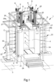
- reference numeral 1 globally indicates a spraying booth.
- the booth 1 comprises:
- the cleaning means 29 are not shown in Figures 1-6 , but are shown in detail in Figures 7-10 .
- the supporting frame 6, 7 is arranged to rest on a stable resting surface 3, i.e., a substantially horizontal flat surface, such as e.g. the ground, as shown in Figure 1 .
- the supporting frame 6, 7 comprises at least one resting element 6 on the stable resting surface 3 of the type of an elongated body extending, in use, vertically.
- the supporting frame 6, 7 comprises a plurality of resting elements 6 and each defining a corresponding fixed resting point on the stable resting surface 3.
- the supporting frame 6, 7 comprises at least one cross member 7, which extends at least partly above the spraying compartment 4 and facing at least partly the access opening 5.
- the cleaning means 29 are mounted on the cross member 7 above the spraying compartment 4 and facing the access opening 5.
- the movement means 40 make the cleaning means 29 vertically movable between the home configuration and the operating configuration.
- the spraying compartment 4 comprises a bedplate 31 opposite the access opening 5.
- the spraying compartment 4 comprises a side wall 10, which extends from the bedplate 31 to end up at the point where the access opening 5 is located. This way, the side wall 10 and the bedplate 31 define a spraying compartment 4 of substantially hollow shape.
- the spraying compartment 4 comprises one or more slits 32, cut through the side wall 10 and adapted to allow the insertion of suitable spraying means 33 into the compartment 4.
- the spraying compartment 4 comprises at least one access port 2 formed on the side wall 10 adapted, e.g., to allow the insertion/removal into/out of the spraying compartment 4 of at least one product to be coated.
- the booth 1 comprises closing/opening means, not shown in the figures, of the access port 2.
- the closing/opening means comprise at least one clamping body coupled in a movable manner to the spraying compartment 4 close to the access port 2, by sealing it, in the operating configuration, and away from the access port 2, by releasing it, in the home configuration.
- the movement means 40 comprise at least one holding boom 8 of the cleaning means 29, mounted movable along a direction of movement A on the supporting frame 6, 7, arranged at least partly inside the spraying compartment 4, if in the operating configuration, and completely outside the spraying compartment 4, if in the home configuration.
- the movement means 40 comprise guidance means 15, 16, 17 of the holding boom 8 along the direction of movement A, inside and outside of the spraying booth 1.
- the movement means 40 comprise actuator means 18, 19, 20, 35, 36, 37, which are adapted to move the holding boom 8 along the direction of movement A.
- the holding boom 8 extends vertically along the direction of movement A.
- the holding boom 8 has a substantially elongated shape along the direction of movement A, so as to reduce the clearance of the same inside the spraying compartment 4.
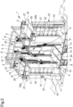
- the holding boom 8 is mounted on the cross member 7, which extends substantially horizontally above the access opening 5, as shown in Figures 3 and 4 .
- the holding boom 8 is a telescopic boom, extending inside the compartment 4 along the direction of movement A, in an operating configuration, and retracted outside the compartment 4 along the direction of movement A, in the home configuration.
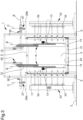
- the holding boom 8 comprises:
- the second stretch 13 is mounted on the first stretch 12 and is made integral by shifting with the latter and following the movement thereof along a predefined first stroke of the first stretch 12 with respect to the supporting frame 6, 7.
- the second stretch 13 is movable with respect to the first stretch 12 along a second predefined stroke.
- the total extension of the holding boom 8 is defined by the sum of the first stroke and of the second stroke.
- the guidance means 15, 16, 17 comprise a first rectilinear guide 15, positioned between the supporting frame 6, 7 and the first stretch 12, and the actuator means 18, 19, 20, 35, 36, 37 comprise a first actuator assembly 18, 35, mounted on at least one of either the supporting frame 6, 7 or the first stretch 12 to move the latter along the first rectilinear guide 15.
- the guidance means 15, 16, 17 comprise a second rectilinear guide 16, positioned between the first stretch and the second stretch 12, 13, and the actuator means 18, 19, 20, 35, 36, 37 comprise a second actuator assembly 19, 36 mounted on at least one of either the first stretch or the second stretch 12, 13, to move the latter along the second rectilinear guide 16.
- first stretch and the second stretch 12, 13 are placed substantially juxtaposed and parallel to each other, in the home configuration, and substantially aligned longitudinally with each other along the direction of movement A, in the operating configuration.
- the holding boom 8 comprises at least one intermediate stretch 14, which is positioned between the first stretch and the second stretch 12, 13 and is coupled movable in a sliding manner along the direction of movement A.
- the intermediate stretch 14 is arranged juxtaposed and substantially parallel to the two stretches 12, 13, in the home configuration, and substantially aligned longitudinally to the two stretches 12, 13 along the direction of movement A, in the operating configuration.
- the intermediate stretch 14 keeps the clearance of the holding boom 8 small, i.e., it does not increase its vertical overhead clearance above the booth 1.
- the guidance means 15, 16, 17 comprise an intermediate rectilinear guide 17, positioned between the intermediate stretch 14 and one of either the first stretch 12 or the second stretch 13.
- the second rectilinear guide 16 is positioned between the intermediate stretch 14 and the other of either the first stretch 12 or the second stretch 13.
- the actuator means 18, 19, 20, 35, 36, 37 comprise an intermediate actuator assembly 20, 37 mounted on at least one of either the intermediate stretch 14, the first stretch 12, or the second stretch 13.
- the holding boom 8 comprises a plurality of intermediate stretches 14 coupled movable and sliding along the direction of movement A to each other, by interposition of respective intermediate rectilinear guides 17, and movable along the same by means of respective intermediate actuator assemblies 20, 37.
- the first stretch and the second stretch 12, 13 have a substantially equal length to the intermediate stretch 14.
- Embodiments of the booth cannot however be ruled out wherein at least one of either the first, the second or the intermediate stretches 12, 13, 14 is longer than at least one of the other stretches 12, 13, 14.
- the stretches 12, 13, 14 have a substantially elongated shape, so as to minimize their clearance inside the spraying compartment 4.
- the first actuator assembly 18, 35 comprises a first actuator 18, mounted on the supporting frame 6, and a first rack 35, associated with the first stretch 12 along the direction of movement A and mechanically coupled to the first actuator 18.
- the intermediate actuator assembly 20, 37 comprises an intermediate actuator 20, mounted on the second stretch 13, and an intermediate rack 37, associated with the intermediate stretch 14 along the direction of movement A and mechanically coupled to the intermediate actuator 20.
- the second actuator assembly 19, 36 comprises a second actuator 19, coinciding with the intermediate actuator 20, and a second rack 36, associated with the first stretch 12 along the direction of movement A and mechanically coupleable to the intermediate actuator 20.
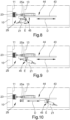
- the intermediate actuator 20 comprises a first gear wheel 38, mechanically coupleable to the second rack 36, and a second gear wheel 39, mechanically coupleable to the intermediate rack 37, as shown in Figures 5 and 6 .
- the intermediate actuator 20 engages the intermediate rack 37 and moves the second stretch 13 facing the intermediate stretch 14, until it allows the second gear wheel 39 to engage the second rack 36 and move the second stretch 13 facing the first stretch 12.
- the movement means 40 comprise securing means, not shown in the figures, of the second stretch 13 to the intermediate stretch 14.
- the securing means are configured to secure the intermediate stretch 14 to the second stretch 13 during the movement of the holding boom 8 from the operating configuration to the home configuration, i.e., during the ascent of the second stretch 13, to also move the intermediate stretch 14 facing the first stretch 12.
- the movement means 40 comprise a plurality of holding booms 8.
- the movement means 40 comprise guidance means 15, 16, 17 and actuator means 18, 19, 20, 35, 36, 37 in the same number as the holding booms 8.
- the holding booms 8 are arranged at the same height and at predefined positions corresponding to the vertices of a square.
- the supporting frame 6, 7 comprises a pair of cross members 7 extending vertically parallel to each other above the access opening 5, on each cross member 7 being mounted a pair of holding booms 8, as shown in Figure 2 .
- the cleaning means 29 comprise at least one cleaning device 21, 23 of the spraying compartment 4, selected from the list comprising a pneumatic dispensing device 21, a hydraulic dispensing device and an absorbing element 23.
- the pneumatic dispensing device 21 is of the type of a dispenser provided with at least one nozzle through which a pressurized air stream is delivered.
- the hydraulic dispensing device is preferably of the type of a dispenser provided with at least one nozzle through which at least one liquid cleaning solution is delivered.
- the characteristics relating to the pneumatic dispensing device 21 are to be considered valid also for the hydraulic dispensing device, since the only difference between these devices lies in the nature of the fluid delivered.
- the absorbing element 23 is of the type of a sponge, a cloth, or the like.
- the absorbing element 23 is a sponge.
- the pneumatic dispensing device 21 is angled downwards, so as to direct the air stream abutting against the vertical walls of the compartment 4 towards the bedplate 31 and not towards the access opening 5.
- the spraying booth 1 comprises suction means 24, that are arranged at the point where the bedplate 31 of the booth itself is located and that are adapted to extract the fluids present inside the spraying compartment 4.
- the suction means 24 coincide with the suction means used for the suction of the paint during the coating steps.
- the cleaning means 29 comprise a plurality of hydraulic dispensing devices, a plurality of pneumatic dispensing devices, and a plurality of absorbing elements 23, each arranged to operate on a predefined portion of the spraying compartment 4, to intervene substantially on the entire perimeter of the compartment itself.
- the cleaning devices 21, 23 vertically explore the perimeter of the spraying compartment 4, by cleaning the entire surface extension of the interior surface 11.
- the pneumatic dispensing device 21 is arranged at a lower height than the absorbing element 23.
- the absorbing element 23 slides in contact with the interior surfaces of the spraying compartment 4 to follow the pneumatic dispensing device 21.
- the movement means 40 comprise at least one holding frame 25a, 25b, associated with the holding boom 8.
- At least one cleaning device 21, 23 is mounted on the holding frame 25a, 25b and, in an operating configuration, is placed facing and/or in contact with the spraying compartment 4, thus cleaning it.
- the holding frame 25a, 25b is associated with the second stretch 13.
- the holding frame 25a, 25b is associated with a plurality of second stretches 13.
- the holding frame 25a, 25b comprises a first supporting element 25a, associated with a pair of second stretches 13, and a second supporting element 25b, associated with another pair of second stretches 13, to substantially define a holding frame 25a, 25b, facing the spraying compartment 4 along its entire perimeter.
- the holding frame 25a, 25b is associated with each second stretch 13 of each holding boom 8 and comprises four connecting elements, which are positioned between corresponding pairs of holding booms 8 respectively, to make a substantially continuous holding frame 25a, 25b of substantially square shape.
- the cleaning devices 21, 23 are mounted on the supporting elements 25a, 25b, so as to operate on the entire perimeter of the interior surface 11.
- the holding frame 25a, 25b defines at least one vacuous portion 41, which allows the passage of external elements, arranged inside the spraying compartment 4, such as e.g. paint dispensers or the like.
- the holding frame 25a, 25b defines at least one vacuous portion 41, at the point where the first supporting element 25a is located, and at least one vacuous portion 41, at the point where the second supporting element 25b is located, as shown in Figure 8 .
- the holding frame 25a, 25b defines a plurality of vacuous portions 41, such as e.g. a pair of vacuous portions 41 at the point where each supporting element 25a, 25b is located.
- the booth 1 comprises operating means 42 of the cleaning means 29 configured to activate/deactivate at least one of the cleaning devices 21, 23.
- the operating means 42 comprise at least one operating assembly, not shown in the figures, positioned between the holding frame 25a, 25b and the absorbing element 23 and configured to move the absorbing element 23 close to the side wall 10, in order to abut against the interior surface 11, and away from the side wall 10.
- the operating assembly moves the absorbing element 23 to abut against the interior surface 11.
- This solution allows the absorbing element 23 to slide in contact with the interior surface 11, thus absorbing any liquids and/or paint residue present thereon.
- the booth 1 comprises displacement means 44, 45 of at least one of the cleaning device 21, 23 between at least a first configuration of use, wherein the cleaning device 21, 23 faces the side wall 10, and at least a second configuration of use, wherein the cleaning device faces the bedplate 31.
- the displacement means 44, 45 comprise at least one rotation assembly 45 of the cleaning device 21, 23 around an axis of rotation E to move the latter between the first and the second configuration of use.
- the displacement means 44, 45 also comprise at least one longitudinal movement assembly 44 of the cleaning device 21, 23 along a direction of displacement D arranged parallel with respect to the bedplate 31.
- the axis of rotation E is transverse with respect to the direction of displacement D.
- the axis of rotation E is orthogonal with respect to the direction of displacement D.
- the rotation assembly 45 is positioned between at least one cleaning device 21, 23 and the longitudinal movement means 44, and the longitudinal movement assembly 44 is positioned between the longitudinal movement means 44 and the rotation assembly 45.
- the longitudinal movement assembly 44 is positioned between at least one holding boom 8 and the rotation assembly 45.
- displacement means 44, 45 cannot be ruled out, wherein the longitudinal movement assembly 44 is positioned between the holding frame 25a, 25b and the rotation assembly 45.
- the longitudinal movement assembly 44 moves the cleaning device 21, 23 along the direction of displacement D, thus cleaning the bedplate 31.
- the longitudinal movement assembly 44 comprises at least one guidance assembly 43 which extends longitudinally along the direction of displacement D and the rotation assembly 45 is coupled in a sliding manner along the guidance assembly 43.
- the cleaning device 21, 23 is a pneumatic dispensing device 21.
- the displacement means 44, 45 are configured to move a plurality of pneumatic dispensing devices 21 arranged aligned with each other along a direction of arrangement substantially parallel to the axis of rotation E.
- pneumatic dispensing device 21 cannot be ruled out, wherein the same comprises a plurality of dispensers arranged aligned with each other along a direction of positioning substantially parallel to the axis of rotation E.
- the displacement means 44, 45 move along the direction of displacement D an individual cleaning device 21, 23 adapted to substantially explore the entire extension of the bedplate 31.
- the booth 1 comprises a pair of displacement means 44, 45 arranged substantially opposite each other.
- the longitudinal movement assemblies 44 move the respective cleaning devices 21, 23 along the direction of displacement D as they approach/move away from each other, as shown in Figures 7-10 .
- each displacement means 44, 45 is associated with a corresponding holding boom 8.
- the booth 1 comprises fastening means 26, 27, 28a, 28b provided with:
- the closure body 28a, 28b is arranged to abut against the spraying compartment 4 at the point where the access opening 5 is located, by hermetically closing and sealing it.
- closure body 28a, 28b is mounted on the supporting frame 6, 7, by interposition of the shifting means 26, 27, and is arranged in the proximity of the access opening 5.
- the shifting means 26, 27 comprise at least one of:
- closure body 28a, 28b is mechanically coupled to the shifting means 26, 27.
- closure body 28a, 28b is arranged substantially at the same height as the access opening 5.
- closure body 28a, 28b is mechanically coupled to the horizontal shifting unit 26 and horizontally movable along the direction of horizontal shift B, to switch from the home configuration to the operating configuration and vice versa.
- the closure body 28a, 28b comprises at least two horizontally movable leaves 28a, 28b that are horizontally movable close to/away from each other to close/release the access opening 5 in the home configuration and in the operating configuration, respectively.
- the shifting means 26, 27 comprise both the horizontal shifting unit 26 and the vertical shifting unit 27.
- the operation of the booth 1 is as follows.
- the movement means 40 move the closure body 28a, 28b away from the spraying compartment 4.
- the vertical shifting unit 27 vertically moves the closure body 28a, 28b away from the compartment 4, vertically spacing the closure body 28a, 28b away from the access opening 5.
- the horizontal shifting unit 26 horizontally moves the closure body 28a, 28b, releasing the access opening 5.
- the horizontal shifting unit 26 moves the leaves 28a, 28b away from each other and arranges them laterally to the access opening 5, by releasing it.
- the movement means 40 move the cleaning means 29 inside the spraying compartment 4.
- the actuator means 18, 19, 20, 35, 36, 37 move the stretches 12, 13, 14 along the direction of movement A, by means of the respective guidance means 15, 16, 17, extending the holding booms 8 inside the spraying compartment 4 and reaching the operating configuration.
- the movement means 40 take the holding booms 8 out of the compartment itself.
- each holding boom 8 is retracted on itself to juxtapose, facing each other, the stretches 12, 13, 14, as shown in Figure 4 .
- the booth 1 comprises spraying means 33 provided with one or more spraying devices 34 insertable in the corresponding slits 32.
- the telescopic structure defined by the coupling of the first stretch, the second stretch and the intermediate stretch significantly reduces the clearance of the holding boom in the home configuration.
Landscapes
- Engineering & Computer Science (AREA)
- Mechanical Engineering (AREA)
- Details Or Accessories Of Spraying Plant Or Apparatus (AREA)
- Seal Device For Vehicle (AREA)
- Apparatuses And Processes For Manufacturing Resistors (AREA)
Claims (10)
- Spritzkabine (1), umfassend:- mindestens ein Sprühabteil (4), das zur Aufnahme der Arbeitsphasen für das Spritzen der zu lackierenden Produkte geeignet und nach oben offen ist, um eine Zugangsöffnung (5) zur Kabine selbst zu definieren;- mindestens einen Tragrahmen (6, 7);- Reinigungsmittel (29), die auf dem Tragrahmen (6, 7) montiert sind und das Innere des Abteils (4) reinigen können;- Bewegungsmittel (40), die zwischen dem Tragrahmen (6, 7) und den Reinigungsmitteln (29) angeordnet ist und ausgebildet sind, letztere zwischen einer Ausgangskonfiguration, in der die Reinigungsmittel (29) außerhalb des Abteils (4) angeordnet sind, und mindestens einer Betriebskonfiguration, in der die Reinigungsmittel (29) durch die Zugangsöffnung (5) innerhalb des Abteils (4) angeordnet sind, zu bewegenwobei die Bewegungsmittel (40) mindestens einen Halteausleger (8) für die Reinigungsmittel (29) umfassen, der entlang einer Bewegungsrichtung (A) beweglich an dem Tragrahmen (6, 7) angebracht ist und in der Betriebskonfiguration zumindest teilweise innerhalb des Sprühabteils (4) und in der Ausgangskonfiguration außerhalb des Sprühabteils (4) angeordnet ist;dadurch gekennzeichnet, dass der Halteausleger (8) ein Teleskopausleger ist, der sich in der Betriebskonfiguration innerhalb des Sprühabteils (4) entlang der Bewegungsrichtung (A) erstreckt und in der Ausgangskonfiguration außerhalb des Sprühabteils (4) entlang der Bewegungsrichtung (A) eingezogen ist.
- Kabine (1) nach Anspruch 1, dadurch gekennzeichnet, dass der Halteausleger (8) umfasst:- mindestens ein erstes Gestänge (12), das entlang der Bewegungsrichtung (A) verschiebbar an dem Tragrahmen (6, 7) angebracht ist;- mindestens ein zweites Gestänge (13), das entlang der Bewegungsrichtung (A) verschiebbar mit dem ersten Gestänge (12) verbunden ist;wobei das erste und das zweite Gestänge (12, 13) in der Ausgangskonfiguration im Wesentlichen nebeneinander und parallel zueinander angeordnet sind und in der Betriebskonfiguration entlang der Bewegungsrichtung (A) voneinander wegbewegt und im Wesentlichen zueinander ausgerichtet sind.
- Kabine (1) nach einem oder mehreren der vorhergehenden Ansprüche, dadurch gekennzeichnet, dass der Halteausleger (8) mindestens ein Zwischengestänge (14) umfasst, das zwischen dem ersten und dem zweiten Gestänge (12, 13) angeordnet ist und mit dem letzteren entlang der Bewegungsrichtung (A) verschiebbar verbunden ist, wobei das Zwischengestänge (14) in der Ausgangskonfiguration im Wesentlichen neben und parallel zu dem ersten und der zweiten Gestänge (12, 13) angeordnet ist und in der Betriebskonfiguration im Wesentlichen zu dem ersten und der zweiten Gestänge (12, 13) entlang der Bewegungsrichtung (A) ausgerichtet ist.
- Kabine (1) nach einem oder mehreren der vorhergehenden Ansprüche, dadurch gekennzeichnet, dass die Bewegungsmittel (40) eine Vielzahl der Halteausleger (8) umfassen.
- Kabine (1) nach einem oder mehreren der vorhergehenden Ansprüche, dadurch gekennzeichnet, dass die Reinigungsmittel (29) mindestens eine Reinigungsvorrichtung (21, 23) des Sprühabteils (4) umfassen, die aus der Liste ausgewählt ist, die eine pneumatische Abgabevorrichtung (21), eine hydraulische Abgabevorrichtung ein absorbierendes Element (23) umfasst.
- Kabine (1) nach einem oder mehreren der vorhergehenden Ansprüche, dadurch gekennzeichnet, dass die Reinigungsmittel (29) eine Vielzahl der Reinigungsvorrichtungen (21, 23) umfassen.
- Kabine (1) nach einem oder mehreren der vorangehenden Ansprüche, dadurch gekennzeichnet, dass- die Bewegungsmittel (40) mindestens einen Halterahmen (25a, 25b) umfassen, der mindestens einem Halteausleger (8) zugeordnet ist;- die mindestens eine Reinigungsvorrichtung (21, 23) an dem Halterahmen (25a, 25b) angebracht ist und in der Betriebskonfiguration dem Sprühabteil (4) zugewandt und/oder in Kontakt mit diesem angeordnet ist, um dieses zu reinigen.
- Kabine (1) nach einem oder mehreren der vorhergehenden Ansprüche, dadurch gekennzeichnet, dass- das Sprühabteil (4) mindestens eine Grundplatte (31) gegenüber der Zugangsöffnung (5) und mindestens eine Seitenwand (10) aufweist, die sich von der Grundplatte (31) aus erstreckt und an der Stelle endet, an der sich die Zugangsöffnung (5) befindet;- sie Mittel (44, 45) zum Bewegen mindestens einer der Reinigungsvorrichtungen (21, 23) zwischen mindestens einer ersten Betriebskonfiguration, in der die mindestens eine Reinigungsvorrichtung (21, 23) der Seitenwand (10) zugewandt ist, und mindestens einer zweiten Betriebskonfiguration umfasst, in der die mindestens eine Reinigungsvorrichtung (21, 23) der Grundplatte (31) zugewandt ist.
- Kabine (1) nach einem oder mehreren der vorhergehenden Ansprüche, dadurch gekennzeichnet, dass sie Befestigungsmittel (26, 27, 28a, 28b) für das Sprühabteil (4) umfasst, das versehen ist mit:- mindestens einem Verschlusskörper (28a, 28b) für die Zugangsöffnung (5), der ausgebildet ist, das Sprühabteil (4) zu schließen;- Verschiebemitteln (26, 27) für den Verschlusskörper (28a, 28b), die sich in der Ausgangskonfiguration der Zugangsöffnung (5) nähern und sie schließen und sich in der Betriebskonfiguration von der Zugangsöffnung (5) wegbewegen und sie freigeben, so dass die Reinigungsmittel (29) in das Innere des Sprühabteils (4) eingeführt werden.
- Kabine (1) nach einem oder mehreren der vorhergehenden Ansprüche, dadurch gekennzeichnet, dass die Verschiebemittel (26, 27) mindestens eines der folgenden Elemente umfassen- mindestens eine Einheit (26) zum horizontalen Verschieben des Verschlusskörpers (28a, 28b) entlang einer horizontalen Verschieberichtung (B);- mindestens eine Einheit (27) zum vertikalen Verschieben des Verschlusskörpers (28a, 28b) entlang einer vertikalen Verschieberichtung (C), die im Wesentlichen quer zur horizontalen Verschieberichtung (B) verläuft.
Applications Claiming Priority (2)
| Application Number | Priority Date | Filing Date | Title |
|---|---|---|---|
| IT102020000007318A IT202000007318A1 (it) | 2020-04-06 | 2020-04-06 | Cabina di verniciatura |
| PCT/IB2021/052610 WO2021205284A1 (en) | 2020-04-06 | 2021-03-30 | Spraying booth |
Publications (2)
| Publication Number | Publication Date |
|---|---|
| EP4132726A1 EP4132726A1 (de) | 2023-02-15 |
| EP4132726B1 true EP4132726B1 (de) | 2024-05-08 |
Family
ID=71094720
Family Applications (1)
| Application Number | Title | Priority Date | Filing Date |
|---|---|---|---|
| EP21722283.5A Active EP4132726B1 (de) | 2020-04-06 | 2021-03-30 | Sprühkabine |
Country Status (3)
| Country | Link |
|---|---|
| EP (1) | EP4132726B1 (de) |
| IT (1) | IT202000007318A1 (de) |
| WO (1) | WO2021205284A1 (de) |
Families Citing this family (2)
| Publication number | Priority date | Publication date | Assignee | Title |
|---|---|---|---|---|
| CN114570544B (zh) * | 2022-03-15 | 2023-06-06 | 广德众泰科技有限公司 | 一种用于线路板生产的喷涂装置及其喷涂方法 |
| CN114798261A (zh) * | 2022-04-28 | 2022-07-29 | 内蒙古工业大学 | 一种基于六轴机械臂的多角度喷涂装置 |
Citations (1)
| Publication number | Priority date | Publication date | Assignee | Title |
|---|---|---|---|---|
| EP3341133B1 (de) * | 2015-08-24 | 2020-09-09 | Siver S.r.l. | Beschichtungskabine |
Family Cites Families (1)
| Publication number | Priority date | Publication date | Assignee | Title |
|---|---|---|---|---|
| US7665414B2 (en) * | 2005-09-19 | 2010-02-23 | Nordson Corporation | Powder coating booth |
-
2020
- 2020-04-06 IT IT102020000007318A patent/IT202000007318A1/it unknown
-
2021
- 2021-03-30 EP EP21722283.5A patent/EP4132726B1/de active Active
- 2021-03-30 WO PCT/IB2021/052610 patent/WO2021205284A1/en not_active Ceased
Patent Citations (1)
| Publication number | Priority date | Publication date | Assignee | Title |
|---|---|---|---|---|
| EP3341133B1 (de) * | 2015-08-24 | 2020-09-09 | Siver S.r.l. | Beschichtungskabine |
Also Published As
| Publication number | Publication date |
|---|---|
| WO2021205284A1 (en) | 2021-10-14 |
| IT202000007318A1 (it) | 2021-10-06 |
| EP4132726A1 (de) | 2023-02-15 |
Similar Documents
| Publication | Publication Date | Title |
|---|---|---|
| EP4132726B1 (de) | Sprühkabine | |
| EP2698232B1 (de) | Lackiereinrichtung | |
| US8453597B2 (en) | Paint shop and corresponding method of operation | |
| EP3012032B1 (de) | Roboter mit einer reinigungseinrichtung und zugehöriges betriebsverfahren | |
| DE60125369T2 (de) | Verfahren und station zum wechseln von flüssigkeit für eine spritzanlage | |
| US9694378B2 (en) | Application robot having a connection unit for different applicators | |
| KR102207462B1 (ko) | 다품종 소량생산이 가능한 가변형 분체도장부스 | |
| KR20150036821A (ko) | 코팅 공장 설비 및 제품의 연속 코팅방법 | |
| EP2658660A1 (de) | Spritzkabine für lackieranlagen für produkte | |
| EP3341133B1 (de) | Beschichtungskabine | |
| KR20030024910A (ko) | 자동화된 도장 설비의 도료 저장조 충전 방법 및 장치 | |
| CN107442343A (zh) | 一种多轴喷漆装置 | |
| DE102010024538A1 (de) | Lackieranlage | |
| CN209662904U (zh) | 一种抑尘设备的高压水雾喷射装置 | |
| DE19722773C1 (de) | Pulverbeschichtungskabine mit drehbarem Kabinenwandträger | |
| US9751103B2 (en) | Varnishing plant for body shops | |
| CN116116598B (zh) | 一种可切换的汽车内饰件喷漆设备 | |
| CN214864769U (zh) | 一种钣金件生产用喷涂装置 | |
| RU2712570C1 (ru) | Распылительная система | |
| CN216826845U (zh) | 一种消防设备生产用喷漆装置 | |
| CN103990573A (zh) | 一种可转位变形喷粉室 | |
| KR102004728B1 (ko) | 분체도장 마감용 도색장치 | |
| CN204842061U (zh) | 一种顶挂式箱内排喷机 | |
| WO2021124178A1 (en) | Painting booth with manual filter-changing system | |
| KR19990002784U (ko) | 자동차 도장 스프레이 부스의 보선 작업용 그레이팅 장치 |
Legal Events
| Date | Code | Title | Description |
|---|---|---|---|
| STAA | Information on the status of an ep patent application or granted ep patent |
Free format text: STATUS: UNKNOWN |
|
| STAA | Information on the status of an ep patent application or granted ep patent |
Free format text: STATUS: THE INTERNATIONAL PUBLICATION HAS BEEN MADE |
|
| PUAI | Public reference made under article 153(3) epc to a published international application that has entered the european phase |
Free format text: ORIGINAL CODE: 0009012 |
|
| STAA | Information on the status of an ep patent application or granted ep patent |
Free format text: STATUS: REQUEST FOR EXAMINATION WAS MADE |
|
| 17P | Request for examination filed |
Effective date: 20221102 |
|
| AK | Designated contracting states |
Kind code of ref document: A1 Designated state(s): AL AT BE BG CH CY CZ DE DK EE ES FI FR GB GR HR HU IE IS IT LI LT LU LV MC MK MT NL NO PL PT RO RS SE SI SK SM TR |
|
| DAV | Request for validation of the european patent (deleted) | ||
| DAX | Request for extension of the european patent (deleted) | ||
| P01 | Opt-out of the competence of the unified patent court (upc) registered |
Effective date: 20230527 |
|
| GRAP | Despatch of communication of intention to grant a patent |
Free format text: ORIGINAL CODE: EPIDOSNIGR1 |
|
| STAA | Information on the status of an ep patent application or granted ep patent |
Free format text: STATUS: GRANT OF PATENT IS INTENDED |
|
| INTG | Intention to grant announced |
Effective date: 20231019 |
|
| GRAJ | Information related to disapproval of communication of intention to grant by the applicant or resumption of examination proceedings by the epo deleted |
Free format text: ORIGINAL CODE: EPIDOSDIGR1 |
|
| STAA | Information on the status of an ep patent application or granted ep patent |
Free format text: STATUS: REQUEST FOR EXAMINATION WAS MADE |
|
| GRAS | Grant fee paid |
Free format text: ORIGINAL CODE: EPIDOSNIGR3 |
|
| STAA | Information on the status of an ep patent application or granted ep patent |
Free format text: STATUS: GRANT OF PATENT IS INTENDED |
|
| GRAP | Despatch of communication of intention to grant a patent |
Free format text: ORIGINAL CODE: EPIDOSNIGR1 |
|
| INTC | Intention to grant announced (deleted) | ||
| INTG | Intention to grant announced |
Effective date: 20240305 |
|
| GRAA | (expected) grant |
Free format text: ORIGINAL CODE: 0009210 |
|
| STAA | Information on the status of an ep patent application or granted ep patent |
Free format text: STATUS: THE PATENT HAS BEEN GRANTED |
|
| AK | Designated contracting states |
Kind code of ref document: B1 Designated state(s): AL AT BE BG CH CY CZ DE DK EE ES FI FR GB GR HR HU IE IS IT LI LT LU LV MC MK MT NL NO PL PT RO RS SE SI SK SM TR |
|
| REG | Reference to a national code |
Ref country code: GB Ref legal event code: FG4D |
|
| REG | Reference to a national code |
Ref country code: CH Ref legal event code: EP |
|
| REG | Reference to a national code |
Ref country code: DE Ref legal event code: R096 Ref document number: 602021013086 Country of ref document: DE |
|
| REG | Reference to a national code |
Ref country code: IE Ref legal event code: FG4D |
|
| REG | Reference to a national code |
Ref country code: LT Ref legal event code: MG9D |
|
| REG | Reference to a national code |
Ref country code: NL Ref legal event code: MP Effective date: 20240508 |
|
| PG25 | Lapsed in a contracting state [announced via postgrant information from national office to epo] |
Ref country code: IS Free format text: LAPSE BECAUSE OF FAILURE TO SUBMIT A TRANSLATION OF THE DESCRIPTION OR TO PAY THE FEE WITHIN THE PRESCRIBED TIME-LIMIT Effective date: 20240908 |
|
| PG25 | Lapsed in a contracting state [announced via postgrant information from national office to epo] |
Ref country code: BG Free format text: LAPSE BECAUSE OF FAILURE TO SUBMIT A TRANSLATION OF THE DESCRIPTION OR TO PAY THE FEE WITHIN THE PRESCRIBED TIME-LIMIT Effective date: 20240508 |
|
| PG25 | Lapsed in a contracting state [announced via postgrant information from national office to epo] |
Ref country code: FI Free format text: LAPSE BECAUSE OF FAILURE TO SUBMIT A TRANSLATION OF THE DESCRIPTION OR TO PAY THE FEE WITHIN THE PRESCRIBED TIME-LIMIT Effective date: 20240508 Ref country code: HR Free format text: LAPSE BECAUSE OF FAILURE TO SUBMIT A TRANSLATION OF THE DESCRIPTION OR TO PAY THE FEE WITHIN THE PRESCRIBED TIME-LIMIT Effective date: 20240508 |
|
| PG25 | Lapsed in a contracting state [announced via postgrant information from national office to epo] |
Ref country code: GR Free format text: LAPSE BECAUSE OF FAILURE TO SUBMIT A TRANSLATION OF THE DESCRIPTION OR TO PAY THE FEE WITHIN THE PRESCRIBED TIME-LIMIT Effective date: 20240809 |
|
| PG25 | Lapsed in a contracting state [announced via postgrant information from national office to epo] |
Ref country code: PT Free format text: LAPSE BECAUSE OF FAILURE TO SUBMIT A TRANSLATION OF THE DESCRIPTION OR TO PAY THE FEE WITHIN THE PRESCRIBED TIME-LIMIT Effective date: 20240909 |
|
| REG | Reference to a national code |
Ref country code: AT Ref legal event code: MK05 Ref document number: 1684568 Country of ref document: AT Kind code of ref document: T Effective date: 20240508 |
|
| PG25 | Lapsed in a contracting state [announced via postgrant information from national office to epo] |
Ref country code: NL Free format text: LAPSE BECAUSE OF FAILURE TO SUBMIT A TRANSLATION OF THE DESCRIPTION OR TO PAY THE FEE WITHIN THE PRESCRIBED TIME-LIMIT Effective date: 20240508 |
|
| PG25 | Lapsed in a contracting state [announced via postgrant information from national office to epo] |
Ref country code: ES Free format text: LAPSE BECAUSE OF FAILURE TO SUBMIT A TRANSLATION OF THE DESCRIPTION OR TO PAY THE FEE WITHIN THE PRESCRIBED TIME-LIMIT Effective date: 20240508 |
|
| PG25 | Lapsed in a contracting state [announced via postgrant information from national office to epo] |
Ref country code: AT Free format text: LAPSE BECAUSE OF FAILURE TO SUBMIT A TRANSLATION OF THE DESCRIPTION OR TO PAY THE FEE WITHIN THE PRESCRIBED TIME-LIMIT Effective date: 20240508 |
|
| PG25 | Lapsed in a contracting state [announced via postgrant information from national office to epo] |
Ref country code: PL Free format text: LAPSE BECAUSE OF FAILURE TO SUBMIT A TRANSLATION OF THE DESCRIPTION OR TO PAY THE FEE WITHIN THE PRESCRIBED TIME-LIMIT Effective date: 20240508 |
|
| PG25 | Lapsed in a contracting state [announced via postgrant information from national office to epo] |
Ref country code: LV Free format text: LAPSE BECAUSE OF FAILURE TO SUBMIT A TRANSLATION OF THE DESCRIPTION OR TO PAY THE FEE WITHIN THE PRESCRIBED TIME-LIMIT Effective date: 20240508 |
|
| PG25 | Lapsed in a contracting state [announced via postgrant information from national office to epo] |
Ref country code: PT Free format text: LAPSE BECAUSE OF FAILURE TO SUBMIT A TRANSLATION OF THE DESCRIPTION OR TO PAY THE FEE WITHIN THE PRESCRIBED TIME-LIMIT Effective date: 20240909 Ref country code: PL Free format text: LAPSE BECAUSE OF FAILURE TO SUBMIT A TRANSLATION OF THE DESCRIPTION OR TO PAY THE FEE WITHIN THE PRESCRIBED TIME-LIMIT Effective date: 20240508 Ref country code: NO Free format text: LAPSE BECAUSE OF FAILURE TO SUBMIT A TRANSLATION OF THE DESCRIPTION OR TO PAY THE FEE WITHIN THE PRESCRIBED TIME-LIMIT Effective date: 20240808 Ref country code: NL Free format text: LAPSE BECAUSE OF FAILURE TO SUBMIT A TRANSLATION OF THE DESCRIPTION OR TO PAY THE FEE WITHIN THE PRESCRIBED TIME-LIMIT Effective date: 20240508 Ref country code: LV Free format text: LAPSE BECAUSE OF FAILURE TO SUBMIT A TRANSLATION OF THE DESCRIPTION OR TO PAY THE FEE WITHIN THE PRESCRIBED TIME-LIMIT Effective date: 20240508 Ref country code: IS Free format text: LAPSE BECAUSE OF FAILURE TO SUBMIT A TRANSLATION OF THE DESCRIPTION OR TO PAY THE FEE WITHIN THE PRESCRIBED TIME-LIMIT Effective date: 20240908 Ref country code: HR Free format text: LAPSE BECAUSE OF FAILURE TO SUBMIT A TRANSLATION OF THE DESCRIPTION OR TO PAY THE FEE WITHIN THE PRESCRIBED TIME-LIMIT Effective date: 20240508 Ref country code: GR Free format text: LAPSE BECAUSE OF FAILURE TO SUBMIT A TRANSLATION OF THE DESCRIPTION OR TO PAY THE FEE WITHIN THE PRESCRIBED TIME-LIMIT Effective date: 20240809 Ref country code: FI Free format text: LAPSE BECAUSE OF FAILURE TO SUBMIT A TRANSLATION OF THE DESCRIPTION OR TO PAY THE FEE WITHIN THE PRESCRIBED TIME-LIMIT Effective date: 20240508 Ref country code: ES Free format text: LAPSE BECAUSE OF FAILURE TO SUBMIT A TRANSLATION OF THE DESCRIPTION OR TO PAY THE FEE WITHIN THE PRESCRIBED TIME-LIMIT Effective date: 20240508 Ref country code: BG Free format text: LAPSE BECAUSE OF FAILURE TO SUBMIT A TRANSLATION OF THE DESCRIPTION OR TO PAY THE FEE WITHIN THE PRESCRIBED TIME-LIMIT Effective date: 20240508 Ref country code: AT Free format text: LAPSE BECAUSE OF FAILURE TO SUBMIT A TRANSLATION OF THE DESCRIPTION OR TO PAY THE FEE WITHIN THE PRESCRIBED TIME-LIMIT Effective date: 20240508 Ref country code: RS Free format text: LAPSE BECAUSE OF FAILURE TO SUBMIT A TRANSLATION OF THE DESCRIPTION OR TO PAY THE FEE WITHIN THE PRESCRIBED TIME-LIMIT Effective date: 20240808 |
|
| PG25 | Lapsed in a contracting state [announced via postgrant information from national office to epo] |
Ref country code: DK Free format text: LAPSE BECAUSE OF FAILURE TO SUBMIT A TRANSLATION OF THE DESCRIPTION OR TO PAY THE FEE WITHIN THE PRESCRIBED TIME-LIMIT Effective date: 20240508 |
|
| PG25 | Lapsed in a contracting state [announced via postgrant information from national office to epo] |
Ref country code: EE Free format text: LAPSE BECAUSE OF FAILURE TO SUBMIT A TRANSLATION OF THE DESCRIPTION OR TO PAY THE FEE WITHIN THE PRESCRIBED TIME-LIMIT Effective date: 20240508 |
|
| PG25 | Lapsed in a contracting state [announced via postgrant information from national office to epo] |
Ref country code: CZ Free format text: LAPSE BECAUSE OF FAILURE TO SUBMIT A TRANSLATION OF THE DESCRIPTION OR TO PAY THE FEE WITHIN THE PRESCRIBED TIME-LIMIT Effective date: 20240508 |
|
| PG25 | Lapsed in a contracting state [announced via postgrant information from national office to epo] |
Ref country code: SK Free format text: LAPSE BECAUSE OF FAILURE TO SUBMIT A TRANSLATION OF THE DESCRIPTION OR TO PAY THE FEE WITHIN THE PRESCRIBED TIME-LIMIT Effective date: 20240508 Ref country code: RO Free format text: LAPSE BECAUSE OF FAILURE TO SUBMIT A TRANSLATION OF THE DESCRIPTION OR TO PAY THE FEE WITHIN THE PRESCRIBED TIME-LIMIT Effective date: 20240508 |
|
| PG25 | Lapsed in a contracting state [announced via postgrant information from national office to epo] |
Ref country code: SM Free format text: LAPSE BECAUSE OF FAILURE TO SUBMIT A TRANSLATION OF THE DESCRIPTION OR TO PAY THE FEE WITHIN THE PRESCRIBED TIME-LIMIT Effective date: 20240508 |
|
| PG25 | Lapsed in a contracting state [announced via postgrant information from national office to epo] |
Ref country code: SM Free format text: LAPSE BECAUSE OF FAILURE TO SUBMIT A TRANSLATION OF THE DESCRIPTION OR TO PAY THE FEE WITHIN THE PRESCRIBED TIME-LIMIT Effective date: 20240508 Ref country code: SK Free format text: LAPSE BECAUSE OF FAILURE TO SUBMIT A TRANSLATION OF THE DESCRIPTION OR TO PAY THE FEE WITHIN THE PRESCRIBED TIME-LIMIT Effective date: 20240508 Ref country code: RO Free format text: LAPSE BECAUSE OF FAILURE TO SUBMIT A TRANSLATION OF THE DESCRIPTION OR TO PAY THE FEE WITHIN THE PRESCRIBED TIME-LIMIT Effective date: 20240508 Ref country code: EE Free format text: LAPSE BECAUSE OF FAILURE TO SUBMIT A TRANSLATION OF THE DESCRIPTION OR TO PAY THE FEE WITHIN THE PRESCRIBED TIME-LIMIT Effective date: 20240508 Ref country code: DK Free format text: LAPSE BECAUSE OF FAILURE TO SUBMIT A TRANSLATION OF THE DESCRIPTION OR TO PAY THE FEE WITHIN THE PRESCRIBED TIME-LIMIT Effective date: 20240508 Ref country code: CZ Free format text: LAPSE BECAUSE OF FAILURE TO SUBMIT A TRANSLATION OF THE DESCRIPTION OR TO PAY THE FEE WITHIN THE PRESCRIBED TIME-LIMIT Effective date: 20240508 |
|
| REG | Reference to a national code |
Ref country code: DE Ref legal event code: R097 Ref document number: 602021013086 Country of ref document: DE |
|
| PLBE | No opposition filed within time limit |
Free format text: ORIGINAL CODE: 0009261 |
|
| STAA | Information on the status of an ep patent application or granted ep patent |
Free format text: STATUS: NO OPPOSITION FILED WITHIN TIME LIMIT |
|
| PGFP | Annual fee paid to national office [announced via postgrant information from national office to epo] |
Ref country code: DE Payment date: 20250327 Year of fee payment: 5 |
|
| 26N | No opposition filed |
Effective date: 20250211 |
|
| PG25 | Lapsed in a contracting state [announced via postgrant information from national office to epo] |
Ref country code: SI Free format text: LAPSE BECAUSE OF FAILURE TO SUBMIT A TRANSLATION OF THE DESCRIPTION OR TO PAY THE FEE WITHIN THE PRESCRIBED TIME-LIMIT Effective date: 20240508 |
|
| PGFP | Annual fee paid to national office [announced via postgrant information from national office to epo] |
Ref country code: BE Payment date: 20250327 Year of fee payment: 5 |
|
| PGFP | Annual fee paid to national office [announced via postgrant information from national office to epo] |
Ref country code: FR Payment date: 20250325 Year of fee payment: 5 |
|
| PGFP | Annual fee paid to national office [announced via postgrant information from national office to epo] |
Ref country code: GB Payment date: 20250327 Year of fee payment: 5 |
|
| PGFP | Annual fee paid to national office [announced via postgrant information from national office to epo] |
Ref country code: TR Payment date: 20250311 Year of fee payment: 5 |
|
| PGFP | Annual fee paid to national office [announced via postgrant information from national office to epo] |
Ref country code: IT Payment date: 20250331 Year of fee payment: 5 |
|
| PG25 | Lapsed in a contracting state [announced via postgrant information from national office to epo] |
Ref country code: SE Free format text: LAPSE BECAUSE OF FAILURE TO SUBMIT A TRANSLATION OF THE DESCRIPTION OR TO PAY THE FEE WITHIN THE PRESCRIBED TIME-LIMIT Effective date: 20240508 |
|
| PG25 | Lapsed in a contracting state [announced via postgrant information from national office to epo] |
Ref country code: MC Free format text: LAPSE BECAUSE OF FAILURE TO SUBMIT A TRANSLATION OF THE DESCRIPTION OR TO PAY THE FEE WITHIN THE PRESCRIBED TIME-LIMIT Effective date: 20240508 |
|
| REG | Reference to a national code |
Ref country code: CH Ref legal event code: H13 Free format text: ST27 STATUS EVENT CODE: U-0-0-H10-H13 (AS PROVIDED BY THE NATIONAL OFFICE) Effective date: 20251023 |
|
| PG25 | Lapsed in a contracting state [announced via postgrant information from national office to epo] |
Ref country code: LU Free format text: LAPSE BECAUSE OF NON-PAYMENT OF DUE FEES Effective date: 20250330 |
|
| PG25 | Lapsed in a contracting state [announced via postgrant information from national office to epo] |
Ref country code: CH Free format text: LAPSE BECAUSE OF NON-PAYMENT OF DUE FEES Effective date: 20250331 |
|
| PG25 | Lapsed in a contracting state [announced via postgrant information from national office to epo] |
Ref country code: IE Free format text: LAPSE BECAUSE OF NON-PAYMENT OF DUE FEES Effective date: 20250330 |