EP4132640B1 - Computer-implementiertes verfahren zur bestimmung von positionen für wandler zur abgabe von tumorbehandlungsfeldern - Google Patents
Computer-implementiertes verfahren zur bestimmung von positionen für wandler zur abgabe von tumorbehandlungsfeldern Download PDFInfo
- Publication number
- EP4132640B1 EP4132640B1 EP21787051.8A EP21787051A EP4132640B1 EP 4132640 B1 EP4132640 B1 EP 4132640B1 EP 21787051 A EP21787051 A EP 21787051A EP 4132640 B1 EP4132640 B1 EP 4132640B1
- Authority
- EP
- European Patent Office
- Prior art keywords
- locations
- subject
- transducer
- transducers
- pairs
- Prior art date
- Legal status (The legal status is an assumption and is not a legal conclusion. Google has not performed a legal analysis and makes no representation as to the accuracy of the status listed.)
- Active
Links
Images


Classifications
-
- A—HUMAN NECESSITIES
- A61—MEDICAL OR VETERINARY SCIENCE; HYGIENE
- A61N—ELECTROTHERAPY; MAGNETOTHERAPY; RADIATION THERAPY; ULTRASOUND THERAPY
- A61N1/00—Electrotherapy; Circuits therefor
- A61N1/40—Applying electric fields by inductive or capacitive coupling ; Applying radio-frequency signals
-
- A—HUMAN NECESSITIES
- A61—MEDICAL OR VETERINARY SCIENCE; HYGIENE
- A61N—ELECTROTHERAPY; MAGNETOTHERAPY; RADIATION THERAPY; ULTRASOUND THERAPY
- A61N1/00—Electrotherapy; Circuits therefor
- A61N1/18—Applying electric currents by contact electrodes
- A61N1/32—Applying electric currents by contact electrodes alternating or intermittent currents
- A61N1/36—Applying electric currents by contact electrodes alternating or intermittent currents for stimulation
- A61N1/36002—Cancer treatment, e.g. tumour
-
- A—HUMAN NECESSITIES
- A61—MEDICAL OR VETERINARY SCIENCE; HYGIENE
- A61N—ELECTROTHERAPY; MAGNETOTHERAPY; RADIATION THERAPY; ULTRASOUND THERAPY
- A61N1/00—Electrotherapy; Circuits therefor
- A61N1/18—Applying electric currents by contact electrodes
- A61N1/32—Applying electric currents by contact electrodes alternating or intermittent currents
- A61N1/36—Applying electric currents by contact electrodes alternating or intermittent currents for stimulation
- A61N1/36014—External stimulators, e.g. with patch electrodes
- A61N1/3603—Control systems
-
- G—PHYSICS
- G16—INFORMATION AND COMMUNICATION TECHNOLOGY [ICT] SPECIALLY ADAPTED FOR SPECIFIC APPLICATION FIELDS
- G16H—HEALTHCARE INFORMATICS, i.e. INFORMATION AND COMMUNICATION TECHNOLOGY [ICT] SPECIALLY ADAPTED FOR THE HANDLING OR PROCESSING OF MEDICAL OR HEALTHCARE DATA
- G16H20/00—ICT specially adapted for therapies or health-improving plans, e.g. for handling prescriptions, for steering therapy or for monitoring patient compliance
- G16H20/30—ICT specially adapted for therapies or health-improving plans, e.g. for handling prescriptions, for steering therapy or for monitoring patient compliance relating to physical therapies or activities, e.g. physiotherapy, acupressure or exercising
-
- G—PHYSICS
- G16—INFORMATION AND COMMUNICATION TECHNOLOGY [ICT] SPECIALLY ADAPTED FOR SPECIFIC APPLICATION FIELDS
- G16H—HEALTHCARE INFORMATICS, i.e. INFORMATION AND COMMUNICATION TECHNOLOGY [ICT] SPECIALLY ADAPTED FOR THE HANDLING OR PROCESSING OF MEDICAL OR HEALTHCARE DATA
- G16H20/00—ICT specially adapted for therapies or health-improving plans, e.g. for handling prescriptions, for steering therapy or for monitoring patient compliance
- G16H20/40—ICT specially adapted for therapies or health-improving plans, e.g. for handling prescriptions, for steering therapy or for monitoring patient compliance relating to mechanical, radiation or invasive therapies, e.g. surgery, laser therapy, dialysis or acupuncture
-
- G—PHYSICS
- G16—INFORMATION AND COMMUNICATION TECHNOLOGY [ICT] SPECIALLY ADAPTED FOR SPECIFIC APPLICATION FIELDS
- G16H—HEALTHCARE INFORMATICS, i.e. INFORMATION AND COMMUNICATION TECHNOLOGY [ICT] SPECIALLY ADAPTED FOR THE HANDLING OR PROCESSING OF MEDICAL OR HEALTHCARE DATA
- G16H50/00—ICT specially adapted for medical diagnosis, medical simulation or medical data mining; ICT specially adapted for detecting, monitoring or modelling epidemics or pandemics
- G16H50/50—ICT specially adapted for medical diagnosis, medical simulation or medical data mining; ICT specially adapted for detecting, monitoring or modelling epidemics or pandemics for simulation or modelling of medical disorders
-
- A—HUMAN NECESSITIES
- A61—MEDICAL OR VETERINARY SCIENCE; HYGIENE
- A61B—DIAGNOSIS; SURGERY; IDENTIFICATION
- A61B34/00—Computer-aided surgery; Manipulators or robots specially adapted for use in surgery
- A61B34/10—Computer-aided planning, simulation or modelling of surgical operations
- A61B2034/101—Computer-aided simulation of surgical operations
- A61B2034/102—Modelling of surgical devices, implants or prosthesis
- A61B2034/104—Modelling the effect of the tool, e.g. the effect of an implanted prosthesis or for predicting the effect of ablation or burring
-
- A—HUMAN NECESSITIES
- A61—MEDICAL OR VETERINARY SCIENCE; HYGIENE
- A61B—DIAGNOSIS; SURGERY; IDENTIFICATION
- A61B34/00—Computer-aided surgery; Manipulators or robots specially adapted for use in surgery
- A61B34/10—Computer-aided planning, simulation or modelling of surgical operations
- A61B2034/101—Computer-aided simulation of surgical operations
- A61B2034/105—Modelling of the patient, e.g. for ligaments or bones
-
- A—HUMAN NECESSITIES
- A61—MEDICAL OR VETERINARY SCIENCE; HYGIENE
- A61N—ELECTROTHERAPY; MAGNETOTHERAPY; RADIATION THERAPY; ULTRASOUND THERAPY
- A61N1/00—Electrotherapy; Circuits therefor
- A61N1/02—Details
- A61N1/04—Electrodes
- A61N1/0404—Electrodes for external use
- A61N1/0408—Use-related aspects
- A61N1/0456—Specially adapted for transcutaneous electrical nerve stimulation [TENS]
-
- A—HUMAN NECESSITIES
- A61—MEDICAL OR VETERINARY SCIENCE; HYGIENE
- A61N—ELECTROTHERAPY; MAGNETOTHERAPY; RADIATION THERAPY; ULTRASOUND THERAPY
- A61N1/00—Electrotherapy; Circuits therefor
- A61N1/02—Details
- A61N1/04—Electrodes
- A61N1/0404—Electrodes for external use
- A61N1/0472—Structure-related aspects
- A61N1/0476—Array electrodes (including any electrode arrangement with more than one electrode for at least one of the polarities)
-
- A—HUMAN NECESSITIES
- A61—MEDICAL OR VETERINARY SCIENCE; HYGIENE
- A61N—ELECTROTHERAPY; MAGNETOTHERAPY; RADIATION THERAPY; ULTRASOUND THERAPY
- A61N1/00—Electrotherapy; Circuits therefor
- A61N1/02—Details
- A61N1/04—Electrodes
- A61N1/0404—Electrodes for external use
- A61N1/0472—Structure-related aspects
- A61N1/0492—Patch electrodes
-
- A—HUMAN NECESSITIES
- A61—MEDICAL OR VETERINARY SCIENCE; HYGIENE
- A61N—ELECTROTHERAPY; MAGNETOTHERAPY; RADIATION THERAPY; ULTRASOUND THERAPY
- A61N1/00—Electrotherapy; Circuits therefor
- A61N1/02—Details
- A61N1/04—Electrodes
- A61N1/06—Electrodes for high-frequency therapy
-
- A—HUMAN NECESSITIES
- A61—MEDICAL OR VETERINARY SCIENCE; HYGIENE
- A61N—ELECTROTHERAPY; MAGNETOTHERAPY; RADIATION THERAPY; ULTRASOUND THERAPY
- A61N1/00—Electrotherapy; Circuits therefor
- A61N1/40—Applying electric fields by inductive or capacitive coupling ; Applying radio-frequency signals
- A61N1/403—Applying electric fields by inductive or capacitive coupling ; Applying radio-frequency signals for thermotherapy, e.g. hyperthermia
Definitions
- This application relates to a method for determining locations for transducers to deliver tumor treating fields.
- Tumor treating fields are low intensity alternating electric fields within the intermediate frequency range, which may be used to treat tumors as described in U.S. Patent No. 7,565,205 .
- TTFields are induced non-invasively into a region of interest by transducers placed on the patient's body and applying AC voltages between the transducers.
- a first pair of transducers and a second pair of transducers are placed on the subject's body.
- AC voltage is applied between the first pair of transducers for a first interval of time to generate an electric field with field lines generally running in the front-back direction.
- AC voltage is applied at the same frequency between the second pair of transducers for a second interval of time to generate an electric field with field lines generally running in the right-left direction.
- the system then repeats this two-step sequence throughout the treatment.
- US-A-2018/0001075 discloses an apparatus and method for treating a target region in a subject's body with tumor treating fields (TTFields), the target region being located in a portion of the subject's body that has a longitudinal axis.
- TFields tumor treating fields
- US-A-2017/0014637 discloses a system comprising a plurality of coils and an electromagnetic field generator that energizes the plurality of coils so as to apply a tumor treating field (TTField) to a specimen region.
- TField tumor treating field
- US-A-2020/0129761 discloses a method of determining where to position sets of electrode elements in applying an alternating electric field to a target region in a person's spinal anatomy.
- US-A-2019/0117956 discloses a method of optimizing positions of a plurality of electrodes placed on a subject's body, where the electrodes are used to impose an electric field in target tissue within an anatomic volume.
- US-A-2020/0114141 discloses a method of applying an alternating electric field to a person's brain.
- US-A-2021/0299439 discloses a method of assisting transducer placements on a subject's body for applying tumor treating fields.
- the present invention is directed to a computer-implemented method to determine placement of transducers on a subject's body for inducing tumor treating fields according to claim 1.
- This application describes exemplary methods and apparatuses to apply TTFields to a torso of a subject's body and may be used to treat one or more cancers located in the torso of the subject's body.
- the torso is the central part of the subject's body including the thorax and the abdomen. Many abdominal cancers may metastasize to the thorax area and vice versa. For this reason, it may be beneficial to deliver TTFields to the entire thorax and abdomen simultaneously.
- Pre-clinical experiments suggest that in order exert a therapeutic effect, TTField intensities should exceed a threshold of about 1 V/cm.
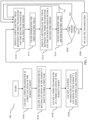
- FIG. 1 describes an example method 100 of applying TTFields to the torso of a subject's body.
- the method 100 comprises locating a first transducer at a first location of the subject's body, wherein the first location is on the torso of the subject's body.
- a second transducer is located at a second location of the subject's body, wherein the second location is below the torso of the subject's body.
- Below the torso of the subject's body may include, for example, on the thigh of the subject's body.
- the first and second transducers form the first pair of transducers.
- the first and second transducers are capacitively coupled. In another example, the transducers are not capacitively coupled.
- a third transducer is located at a third location of the subject's body, wherein the third location is on the torso of the subject's body and is not overlapping with the first location.
- a fourth transducer is located at a fourth location of the subject's body, wherein the fourth location is below the torso of the subject's body and is not overlapping with the second location.
- the third and fourth transducers form the second pair of transducers.
- the third and fourth transducers are capacitively coupled. In another example, the transducers are not capacitively coupled.
- the transducers may be electric field generators.
- One or more of the first, second, third, and the fourth transducers may comprise an array, or grouping of electrode elements. Each array of electrode elements may comprise a plurality of ceramic disks, each disk being approximately 2 cm in diameter and approximately 1 mm in thickness. Each transducer may cover a surface area of approximately 140 to 250 cm 2 .
- a first electric field is induced between the first transducer and the second transducer for a first time period.
- the first electric field is induced by applying a first AC voltage generated by an AC generator to the first pair of transducers and has, for example, a low intensity (e.g., 1-4 V/cm) and intermediate frequency range (e.g., 125-250 kHz, or in some cases, 50-500 kHz).
- the first AC voltage is applied to the first pair of transducers for the first time period (e.g., one second).
- the generation of the first electric field is ceased. That is, the AC generator stops generating the first AC voltage.
- a second electric field is induced between the third transducer and the fourth transducer for a second time period.
- the second electric field is induced by applying a second AC voltage generated by the AC generator to the second pair of transducers.
- the second electric field may or may not have the same intensity and frequency as the first electric field.
- the second AC voltage is applied to the second pair of transducers for the second time period.
- the first time period and the second time period may be the same or different.
- the generation of the second electric field is ceased. That is, the AC generator stops generating the second AC voltage.
- the process automatically repeats (arrow 118) in steps S110, S112, S114, and S116.
- the electric fields are induced in a thorax and an abdomen of the subject's body.
- the method 100 may further include changing the locations of the subject's body where the electric field is applied. This may help to mitigate the risk of skin irritation, thereby reducing any discomfort of the subject.
- the method 100 may include steps S502 and S504.
- a third time period is checked. The third time period (which may be in hours or days) determines when the locations of the transducers should be changed. Once the third time period has ended, the locations of the transducers are moved to new locations on the subject's body. If the third time period is not over, flow proceeds to step S110. If the third time period is over, flow proceeds to step S504. At step S504, the transducers are re-located on the subject's body.
- the first transducer, the second transducer, the third transducer and the fourth transducer are re-located to a new first location, a new second location, a new third location, and a new fourth location of the subject's body.
- the new first, second, third, and fourth locations do not overlap with the previous first, second, third, and fourth locations, respectively. In alternative embodiments, the new locations may partially overlap with the previous locations.
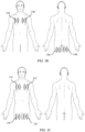
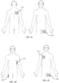
- FIG. 2 depicts an example of a transducer layout for applying TTFields to a subject's body.
- FIG. 2 depicts one example of a transducer layout of two pairs of transducers with four transducers used for applying TTFields to the torso of the subject's body.
- the first transducer 21A and the third transducer 23A are located on the thorax of the subject's body
- the second transducer 22A and the fourth transducer 24A are located on the thighs of the subject's body.
- the first transducer 21A is located on the front of the thorax
- the third transducer 23A is located on the back of the thorax
- the second transducer 22A is located on a back or an outer side of the thighs
- the fourth transducer 24A is located on the front or inside of the thighs.
- the first transducer 21A is located on the front of the right thorax
- the third transducer 23A is located on the back of the left thorax
- the second transducer 22A is located on the back of the left thigh
- the fourth transducer 24A is located on the front of the right thigh.
- first transducer 21A and the second transducer 22A may form a first pair of transducers
- the third transducer 23A and the fourth transducer 24A may form a second pair of transducers.
- more than two pairs of transducers may be used for applying TTFields to the subject's body.
- FIGS. 3A-3E depict examples of transducer layouts with two pairs of transducers for applying TTFields to the subject's torso.
- the first transducer 31A is located on the front of the right thorax
- the second transducer 32A is located on the back of the left thigh
- the third transducer 33A is located on the back of the right thorax
- the fourth transducer 34A is located on the front of the left thigh.
- the first and second transducers 31A and 32A may form a first pair of transducers
- the third and fourth transducers 33A and 34A may form a second pair of transducers.
- the first and fourth transducers 31A and 34A may form a first pair of transducers
- the third and second transducers 33A and 32A may form a second pair of transducers.
- the first transducer 31D is located on the front of the thorax
- the second transducer 32D and the fourth transducer 34D are located on the back of the left thigh and on the back of the right thigh, respectively.
- a first part 33D of the first transducer 31D and the second transducer 32D may form a first pair of transducers
- a second part 35D of the first transducer 31D and the fourth transducer 34D may form a second pair of transducers.
- the first part of the first transducer 33D does not overlap with the second part of the first transducer 35D.
- the first part of the first transducer 33D may partially overlap with the second part of the first transducer 35D.
- the first transducer 31E is located on the front of the right thorax
- the third transducer 33E is located on the back of the right thorax
- the second transducer 32E is located on the front of the left thigh.
- the first and second transducers 31E and 32E may form a first pair of transducers
- the third and second transducers 33E and 32E may form a second pair of transducers.
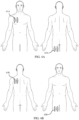
- FIGS. 4A-4E depict examples of transducer layouts with one pair of transducers for applying TTFields to the torso of the subject's body. Various combinations of these pairs of transducers or similar pairs of transducers may be used together.
- the first transducer 41A is located on the front of the right thorax
- the second transducer 42A is located on the back of the left thigh.
- the first transducer 41B is located on the back of the left thorax
- the second transducer 42B is located on the front of the right thigh.
- the first transducer 41C is located on the back of the right thorax, and the second transducer 42C is located on the front of the left thigh.
- the first transducer 41D is located below the left armpit, and the second transducer 42D is located on the outer side of the right thigh. Instead of the outer side of the thigh, the transducer may be located on the inner side of the thigh.
- the first transducer 41E is located on the front of the right thorax, and the second transducer 42E is located on the front of the left thigh.
- the locations of the transducers that are located below the torso may be flexible.
- the location of the second transducer may be anywhere on the thigh of the subject's body (e.g., on a front, back, outer side, or inner side of a thigh, a combination thereof, or a partially or fully overlapping combination thereof).
- transducers may be used together.
- locations of transducers such as those discussed herein or in other locations, may be used.
- a transducer may be used in a single pair of transducers or in two or more pairs of transducers.
- a transducer may be partitioned to be used in a single pair of transducers or in two or more pairs of transducers. The transducers, the transducer locations, the pairs of transducers, and the two or more pairs of transducers discussed herein are not exhaustive.
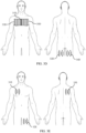
- FIGS. 5A and 5B depict examples of re-locating the transducers on the torso of the subject's body.
- the first transducer was located at the first location 61A and re-located at the third location 63A.
- the second transducer was located at the second location 62A and re-located at the fourth location 64A.
- the first location 61A is on the front of the right thorax
- the third location 63A is on the back of the right thorax
- the second location 62A is the back of the left thigh
- the fourth location 64A is the front of the left thigh.
- the first transducer was located at the first location 61B and re-located at the third location 63B.
- the second transducer was located at the second location 62B and re-located at the fourth location 64B.
- the first location 61B is below the left armpit
- the third location 63B is below the right armpit
- the second location 62B is on the outer side of the right thigh
- the fourth location 64B is on the outer side of the left thigh.
- the transducers may be re-located to different areas of the subject's body than those illustrated in the examples of FIGS. 5A and 5B .
- the transducers may be re-located to areas of the subject's body to deliver a similar or complementary amount of TTFields.
- the structure of the transducers may take many forms.
- the transducers may be affixed to the subject's body or attached to or incorporated in clothing covering the subject's body.
- the transducer 80A has a substrate 81A and a plurality of electrode elements 82A positioned on the substrate 81A.
- the substrate 81A is configured for attaching the transducer 80A to a subject's body. Suitable materials for the substrate 81A include, for example, cloth, foam, flexible plastic, and/or a conductive medical gel.
- the substrate 81A may be a layer of conducting medical gel with a minimum thickness of 0.5 mm. In this situation, the transducer 80A is affixed to the subject's body via the substrate 81A.
- the transducer may be conductive or nonconductive.
- FIG. 6B depicts another example of the structure of the transducer 80B.
- the transducer 80B includes a plurality of electrode elements 82B that are electrically and mechanically connected to one another without a substrate.
- the electrode elements 82B are connected to each other through conductive wires 83B.
- the transducer may include any desired number of electrode elements 82A, 82B. Various shapes, sizes, and materials may be used for the electrode elements 82A, 82B. Any constructions for implementing the transducer (or electric field generating device) for use with embodiments of the invention may be used, as long as they are capable of (a) delivering TTFields to the subject's body and (b) being positioned at the locations specified herein.
- FIG. 7 depicts one example of the configuration of one pair of transducers.
- the first transducer 901 includes 13 electrode elements 903 which are positioned on the substrate 904 and electrically and mechanically connected to one another through a conductive wiring 909.
- the second transducer 902 includes 20 electrode elements 905 which are positioned on the substrate 906 and electrically and mechanically connected to one another through a conductive wiring 910.
- the first transducer 901 and the second transducer 902 are connected to an AC voltage generator 907 and a controller 908.
- the controller 908 may include one or more processors and memory accessible by the one or more processors.
- the memory may store instructions that when executed by the one or more processors control the AC voltage generator 907 to implement one or more embodiments of the invention (e.g., by providing a first voltage to the first transducer and a second voltage to the second transducer).
- FIG. 8 depicts an exemplary apparatus to determine locations of transducers for applying TTFields.
- the apparatus 1000 includes one or more processors 1002, one or more output devices 1005, and a memory 1003.
- the memory 1003 is accessible by the one or more processors 1002 via a link 1004 so the one or more processors 1002 can read information from and write information to the memory 1003.
- the one or more processors 1002 based on user input 1001, the one or more processors 1002 generate simulation results of a plurality of locations for attaching transducers, rank the plurality of locations, and make one or more recommendations to a user based on the ranking, which are output on the output devices 1005.
- the user may give feedback regarding the one or more recommendations through the output devices 1005, and the one or more processors 1002 may generate different recommendations based on the feedback.
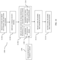
- FIG. 9 is a flowchart describing an example method 300 for determining locations of transducers on a subject's body for applying TTFields.
- a plurality of first locations of the subject's body are selected to locate a first transducer, wherein the plurality of first locations are on the torso of the subject's body.
- a plurality of second locations of the subject's body are selected to locate a second transducer, wherein the plurality of second locations are below the torso of the subject's body. Below the torso of the subject's body may include, for example, on the thigh of the subject's body.
- pairs of first locations and second locations are selected. Each pair has one first location selected from the plurality of first locations and one second location selected from the plurality of second locations, and each pair has a different combination of first and second locations.
- the method 300 may incorporate a measure of heat removal potential of a subject's body to determine locations of transducers on the subject's body for applying TTFields.
- the method 300 may include accessing a mapping of heat removal potential at surface locations corresponding to surface locations of the subject's body.
- step S1102 may include accessing a mapping of the subject's body indicating a heat removal potential at multiple surface locations of the subject's body, as discussed below.
- simulation results for an induced electric field in the torso of the subject's body are generated.
- Generating simulation results may include, for example: obtaining a three-dimensional model of AC electrical conductivity of the relevant anatomic volume; identifying the volume targeted for treatment within the three-dimensional model; automatically placing transducers on the three-dimensional model and setting relevant boundary conditions for the three-dimensional model; and calculating the electric field that develops within the model (e.g., using a Finite Element method analysis) once transducers have been placed on the model and boundary conditions applied.
- the induced electric field in the torso of the subject's body is simulated based at least partially on the mapping of heat removal potential accessed at step S1102 to obtain the simulation results.
- a ranking of the simulations results of each pair of locations is generated. This may involve, for example, running an optimization algorithm to find the layout that yields optimal electric field distributions within the target volume.
- the simulation results may be ranked in order of maximized electric field within the diseased regions of the subject's body.
- one or more recommendations of the pairs of first locations and second locations are generated. In an embodiment, the one or more ranked simulation results are selected based at least partially on the mapping of heat removal potential accessed at step S1102.
- the one or more recommended pairs of first locations and second locations are output to the user.
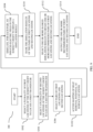
- FIG. 10 is a flowchart describing an example computer-implemented method for determining locations of transducers on a subject's body for applying TTFields.
- the computer comprises one or more processors and a memory accessible by the one or more processors, the memory storing instructions that when executed by the one or more processors cause the computer to perform the method 1300.
- pairs of first locations and second locations are selected, each pair of locations having a first location to locate a first transducer and a second location to locate a second transducer.
- Each pair may have one first location selected from a plurality of first locations and one second location selected from a plurality of second locations.
- Each pair may have a different combination of first locations and second locations.
- One or more of the pairs of locations may include at least one location on the subject's torso.
- a three-dimensional model of AC electrical conductivity (e.g., at the frequency that will be used for the TTFields treatment) of the relevant anatomic volume is obtained using any of a variety of approaches that will be apparent to persons skilled in the relevant arts.
- This three-dimensional model specifies the conductivity of each voxel.
- the method 1300 comprises obtaining, for each location in the plurality of pairs of locations on the subject's body, an indication of heat removal potential at a surface of the subject's body.
- the indication of heat removal potential at the surface of the subject's body may be proportional to an amount of blood circulation proximate the surface at the location of the subject's body.
- the indication of heat removal potential at the surface of the subject's body may be proportional to an amount of muscle mass at the location of the subject's body. Even though muscle movement generates heat, areas of high muscle mass in a subject's body are generally more effective than areas of low muscle mass at moving heat away from the surface of the body due to increased blood circulation through the muscle.
- the indication of heat removal potential at the surface of the subject's body may relate to an amount of sweat expected at the location of the subject's body, an amount of glandular tissue at the location, or whether clothing is expected to cover the location.
- the method at step S 1306 may include accessing a mapping 1308 of relative muscle mass at surface locations of the subject's body; and obtaining, for each location in the plurality of pairs of locations on the subject's body, the amount of muscle mass at the location of the subject's body from the mapping 1308.
- the mapping may be a model of a human body including at least one portion of the body divided into a plurality of zones on the surface of the at least one portion of the body, and a relative muscle mass value corresponding to each zone.
- the mapping 1308 is selected from one or more predetermined models of muscle mass distribution in humans.
- the mapping 1308 may be: a standard mapping of relative muscle mass used for all human subjects; selected from a group of two standard mappings (for male subjects and female subjects) of relative muscle mass; or selected from a finite number of mappings of relative muscle mass in response to one or more user inputs such as, for example, sex, height, and weight.
- the mapping 1308 of relative muscle mass is generated for an individual subject based on an input of at least one measurement 1309 of the subject's body.
- Such measurements 1309 may include a height, weight, circumferential measurements of one or more of the subject's body parts (e.g., chest, waist, hips, forearm, wrist, neck, etc.), grip strength measurement, caliper measurement, or image data, among others.
- the indication of heat removal potential at the surface of the subject's body may be proportional to a concentration of at least one of veins, arteries, or capillaries proximate the surface at the location of the subject's body.
- This relationship takes advantage of vascular changes that occur in a subject's body, such as constriction or enlargement of vessels in response to temperature changes (e.g., blood vessels expanding to remove heat from the area).
- Areas of the subject's body having more veins, arteries, and/or capillaries close to the surface may provide greater heat removal potential.
- the method at step S 1306 may include accessing a mapping 1310 of at least one of veins, arteries, or capillaries proximate surface locations of the subject's body; and obtaining, for each location in the plurality of pairs of locations on the subject's body, the concentration of at least one of veins, arteries, or capillaries proximate the surface at the location of the subject's body from the mapping 1310.
- the mapping 1310 may be a model of a human body including at least one portion of the body divided into a plurality of zones each representing part of the surface of the at least one portion of the body, and a concentration of at least one of veins, arteries, or capillaries proximate the surface corresponding to each zone.
- the mapping 1310 is selected from one or more predetermined models representing a typical circulatory system in humans.
- the mapping 1310 may be: a standard mapping of concentrations of veins, arteries, and/or capillaries used for all human subjects; selected from a group of two standard mappings (for male subjects and female subjects) of a circulatory system; or generated based on image data for the subject.
- the method 1300 comprises selecting one or more recommended pairs of first locations and second locations.
- the one or more recommended pairs are selected based at least on the model of AC electrical conductivity of S1304 and the indication of heat removal potential of S1306 for each location. Since the one or more recommend pairs are selected based on the indication of heat removal potential of S1306, the one or more recommended pairs may include a location having a relatively high muscle mass, a high concentration of veins, arteries, and/or capillaries, and/or other markers of increased circulation.
- the one or more recommended pairs may comprise a location in a region of a torso of the subject.
- the one or more recommended pairs may comprise a location in a region of a shoulder, thigh, or thorax of the subject.
- the method 1300 comprises outputting (e.g., to a user) the one or more recommended pairs of first locations and second locations.
- FIG. 11 is a flowchart depicting an example method of performing step S 1312 of FIG. 10 .
- the method may comprise simulating, for each pair of locations, an induced electric field in the portion of the subject's body between the first transducer and the second transducer of each pair, based on the model of AC electrical conductivity (S 1304 of FIG. 10 ) and the indication of heat removal potential (S 1306 of FIG. 10 ) at the surface of the subject's body for the locations of each pair.
- the indication of heat removal potential may be input to simulation software to generate the results.
- the heat removal potential at the pair locations may affect an amount of energy output via the transducers, since higher heat removal potential enables a subject's body to remove heat caused by transducers operating at higher power levels.
- the simulation may involve applying a weighting factor to transducer locations based on their heat removal potential.
- the method may comprise ranking simulation results of the pairs of first locations and second locations.
- the method may comprise selecting one or more ranked simulation results as the one or more recommended location pairs.
- FIG. 12 is a flowchart depicting another example method of performing step S1312 of FIG. 10 .
- the method may comprise simulating, for each pair of locations, an induced electric field in the portion of the subject's body between the first transducer and the second transducer of each pair based on the model of AC electrical conductivity (S1304 of FIG. 10 ).
- the method may comprise ranking the simulation results of the pairs of first locations and second locations.
- the method may comprise selecting two or more potential pairs of first locations and second locations based on the ranked simulation results.
- the method may comprise comparing the indication of heat removal potential (S1306 of FIG.
- the method may comprise selecting one or more potential pairs having a highest indication of heat removal potential as the one or more recommended pairs of first locations and second locations.
- the method of FIG. 12 involves using the indication of heat removal potential for various surface locations on the subject's body to break a tie between a plurality of transducer location pairs that according to the simulation results would yield substantially similar electric field deliveries to the target region.
- Table 1 shows simulation results for Sample Nos. 1-8 based on step S308 in FIG. 9 .
- Each transducer layout of Sample Nos. 1-8 includes one pair of transducers (a first transducer and a second transducer).
- Each transducer in Sample Nos. 1-3, 5, 7, and 8 include 13 electrode elements, and each transducer in Sample Nos. 4 and 6 include 20 electrode elements.
- All of the field intensities depicted herein were generated by running simulations at 150 kHz using a DUKE model by ZMT (Zürich), a highly detailed computational human male phantom. The simulations were performed using the low frequency solver of the Sim4Life software package, which uses a Finite Differences Method to solve the model.
- the model was voxelized with a maximum resolution of 0.625 mm around the disks. In one example, the resolution within the body was between 1 and 2 mm.
- Dirichlet conditions e.g., constant voltage at a frequency of 150 kHz
- All disks within one pair of transducers were set to the same voltage level.
- the difference in voltage between the two transducers within the pair was set so that the average current per-disk was 200 mA peak to peak, which resulted in the total current of 2.6 A peak to peak for transducers with 13 disks and 4 A peak to peak for transducers with 20 disks.
- the numbers of electrode elements in each transducer and the locations of each transducer on the subject's body are provided in Table 1.
- the simulation results are also provided in Table 1.
- the simulation results include a mean electric field intensity in the torso and a percentage of the torso volume that received an intensity above 1 V/cm. Table 1.
- Simulation results of a plurality of transducer layouts Sample No. 1 st transducer location No. of electrode elements for 1st transducer 2 nd transducer location No. of electrode elements for 2nd transducer Illustrative Figure Simulation results Mean field intensity (V/cm) % volume above 1 V/cm 1 Front right thorax 13 Back left thigh 13 FIG.
- the torso of the subject's body has an average electric field intensity of at least 1.0 V/cm, and at least 50% of volume of the torso of the subject's body has electric field intensities of at least 1.0 V/cm. From the simulation results of Sample Nos. 4 and 6, the torso of the subject's body has an average electric field intensity of at least 1.6 V/cm, and at least 80% of volume of the torso of the subject's body has electric field intensities of at least 1.0 V/cm.
- the simulation results show that placing the transducers in the front or in the back of the thorax does not significantly influence the mean electric field intensity and the percentage of torso volume that received an intensity above 1 V/cm.
- the locations of the transducers may be selected based on comfort level and convenience without compromising the treatment effects of the TTFields.
Landscapes
- Health & Medical Sciences (AREA)
- Engineering & Computer Science (AREA)
- Public Health (AREA)
- General Health & Medical Sciences (AREA)
- Life Sciences & Earth Sciences (AREA)
- Nuclear Medicine, Radiotherapy & Molecular Imaging (AREA)
- Biomedical Technology (AREA)
- Medical Informatics (AREA)
- Radiology & Medical Imaging (AREA)
- Animal Behavior & Ethology (AREA)
- Veterinary Medicine (AREA)
- Epidemiology (AREA)
- Primary Health Care (AREA)
- Oncology (AREA)
- Hospice & Palliative Care (AREA)
- Biophysics (AREA)
- Surgery (AREA)
- Urology & Nephrology (AREA)
- Pathology (AREA)
- Databases & Information Systems (AREA)
- Data Mining & Analysis (AREA)
- Physical Education & Sports Medicine (AREA)
- Heart & Thoracic Surgery (AREA)
- Electrotherapy Devices (AREA)
- Thermotherapy And Cooling Therapy Devices (AREA)
- Measurement Of The Respiration, Hearing Ability, Form, And Blood Characteristics Of Living Organisms (AREA)
- Surgical Instruments (AREA)
Claims (4)
- Computerimplementiertes Verfahren zum Bestimmen der Platzierung von Wandlern (21A, 22A, 23A, 24A; 31A, 32A, 33A, 34A; 31B, 32B, 33B, 34B; 31C, 32C, 33C, 34C; 31D, 32D, 33D, 34D, 35D; 31E, 32E, 33E; 41A-E, 42A-E; 61A, B, 62A, B, 63A, B, 64A, B) auf dem Körper eines Subjekts zum Induzieren von Tumorbehandlungsfeldern, wobei der Computer einen oder mehrere Prozessoren (1002) und einen Speicher (1003) umfasst, auf den der eine oder die mehreren Prozessoren (1002) zugreifen können, wobei der Speicher (1003) Anweisungen speichert, die, wenn sie von dem einen oder den mehreren Prozessoren (1002) ausgeführt werden, den Computer veranlassen, das Verfahren auszuführen, wobei das Verfahren umfasst:Auswählen einer Vielzahl von Paaren von Stellen auf dem Körper des Subjekts, wobei jedes Paar von Stellen eine erste Stelle aufweist, um einen ersten Wandler zu platzieren, und eine zweite Stelle, um einen zweiten Wandler zu platzieren;Erhalten eines Modells der elektrischen AC-Leitfähigkeit in einem Teil des Körpers des Subjekts;Erhalten für jede Stelle in den Paaren von Stellen eine Angabe des Wärmeabfuhrpotentials an einer Oberfläche des Körpers des Subjekts;Auswählen eines oder mehrerer empfohlener Paare von ersten und zweiten Stellen basierend zumindest auf dem Modell der elektrischen AC-Leitfähigkeit und der Angabe des Wärmeabfuhrpotentials für jede Stelle; undAusgeben der einen oder mehreren empfohlenen Paare von ersten und zweiten Stellen.
- Verfahren nach Anspruch 1, ferner umfassend:Simulieren eines induzierten elektrischen Feldes in dem Teil des Körpers des Subjekts zwischen dem ersten Wandler und dem zweiten Wandler jedes Paares, basierend auf dem Modell der elektrischen AC-Leitfähigkeit und der Angabe des Wärmeabfuhrpotentials an der Oberfläche des Körpers des Subjekts für die Stellen jedes Paares;Rangieren der Simulationsergebnisse der Paare von ersten und zweiten Stellen; undAuswählen eines oder mehrerer empfohlener Paare von ersten und zweiten Stellen aus den rangierten Simulationsergebnissen.
- Verfahren nach Anspruch 1, ferner umfassend:Simulieren, für jedes Paar von Stellen, eines induzierten elektrischen Feldes in dem Teil des Körpers des Subjekts zwischen dem ersten Wandler und dem zweiten Wandler jedes Paares, basierend auf dem Modell der elektrischen AC-Leitfähigkeit;Rangieren der Simulationsergebnisse der Paare von ersten und zweiten Stellen;Auswählen von zwei oder mehr potenziellen Paaren von ersten und zweiten Stellen basierend auf den rangierten Simulationsergebnissen;Vergleichen der Angabe des Wärmeabfuhrpotenzials an der Oberfläche des Körpers des Subjekts für Stellen der zwei oder mehr potenziellen Paare von ersten und zweiten Stellen; undAuswählen eines oder mehrerer der potentiellen Paare von ersten und zweiten Orten mit der höchsten Angabe des Wärmeabfuhrpotentials als das eine oder die mehreren empfohlenen Paare von ersten und zweiten Stellen.
- Verfahren nach einem der Ansprüche 1 bis 3, wobei die Angabe des Wärmeabfuhrpotenzials an der Oberfläche des Körpers des Subjekts proportional zu mindestens einer der folgenden Größen ist:einer Menge der Blutzirkulation in der Nähe der Oberfläche an der Stelle des Körpers der Person;einer Menge an Muskelmasse an der Stelle des Körpers des Subjekts; odereiner Konzentration von mindestens einem der Elemente Venen, Arterien oder Kapillaren in der Nähe der Oberfläche an der Stelle des Körpers des Subjekts.
Priority Applications (1)
| Application Number | Priority Date | Filing Date | Title |
|---|---|---|---|
| EP23170927.0A EP4226967A1 (de) | 2020-09-30 | 2021-09-29 | Vorrichtung zur verabreichung von tumorbehandlungsfeldern an einen oberkörper |
Applications Claiming Priority (4)
| Application Number | Priority Date | Filing Date | Title |
|---|---|---|---|
| US202063085934P | 2020-09-30 | 2020-09-30 | |
| US202163181031P | 2021-04-28 | 2021-04-28 | |
| US17/487,432 US12194295B2 (en) | 2020-09-30 | 2021-09-28 | Method and apparatus for delivering tumor treating fields to a torso, and method for determining locations for transducers to deliver tumor treating fields |
| PCT/IB2021/058877 WO2022070047A2 (en) | 2020-09-30 | 2021-09-29 | Method and apparatus for delivering tumor treating fields to a torso, and method for determining locations for transducers to deliver tumor treating fields |
Related Child Applications (2)
| Application Number | Title | Priority Date | Filing Date |
|---|---|---|---|
| EP23170927.0A Division EP4226967A1 (de) | 2020-09-30 | 2021-09-29 | Vorrichtung zur verabreichung von tumorbehandlungsfeldern an einen oberkörper |
| EP23170927.0A Division-Into EP4226967A1 (de) | 2020-09-30 | 2021-09-29 | Vorrichtung zur verabreichung von tumorbehandlungsfeldern an einen oberkörper |
Publications (3)
| Publication Number | Publication Date |
|---|---|
| EP4132640A2 EP4132640A2 (de) | 2023-02-15 |
| EP4132640B1 true EP4132640B1 (de) | 2025-06-18 |
| EP4132640C0 EP4132640C0 (de) | 2025-06-18 |
Family
ID=80823211
Family Applications (2)
| Application Number | Title | Priority Date | Filing Date |
|---|---|---|---|
| EP21787051.8A Active EP4132640B1 (de) | 2020-09-30 | 2021-09-29 | Computer-implementiertes verfahren zur bestimmung von positionen für wandler zur abgabe von tumorbehandlungsfeldern |
| EP23170927.0A Pending EP4226967A1 (de) | 2020-09-30 | 2021-09-29 | Vorrichtung zur verabreichung von tumorbehandlungsfeldern an einen oberkörper |
Family Applications After (1)
| Application Number | Title | Priority Date | Filing Date |
|---|---|---|---|
| EP23170927.0A Pending EP4226967A1 (de) | 2020-09-30 | 2021-09-29 | Vorrichtung zur verabreichung von tumorbehandlungsfeldern an einen oberkörper |
Country Status (6)
| Country | Link |
|---|---|
| US (2) | US12194295B2 (de) |
| EP (2) | EP4132640B1 (de) |
| JP (1) | JP2023543511A (de) |
| CN (1) | CN116322900A (de) |
| TW (1) | TW202235118A (de) |
| WO (1) | WO2022070047A2 (de) |
Families Citing this family (5)
| Publication number | Priority date | Publication date | Assignee | Title |
|---|---|---|---|---|
| AU2017289870B2 (en) * | 2016-06-30 | 2021-12-23 | Novocure Gmbh | Arrays for longitudinal delivery of TTFields to a body |
| EP4547277A1 (de) * | 2022-06-29 | 2025-05-07 | Novocure GmbH | Behandlung des akuten atemnotsyndroms mit alternierenden elektrischen feldern |
| WO2024079716A1 (en) * | 2022-10-14 | 2024-04-18 | Novocure Gmbh | Method and apparatus for small array dose distribution of alternating electric fields |
| WO2025012879A1 (en) * | 2023-07-12 | 2025-01-16 | Novocure Gmbh | Apparatuses, methods, and systems for treating spinal tumors with tumor treating fields |
| WO2025068820A1 (en) | 2023-09-29 | 2025-04-03 | Novocure Gmbh | Thermal mapping for treatment planning for tumor treating fields |
Family Cites Families (11)
| Publication number | Priority date | Publication date | Assignee | Title |
|---|---|---|---|---|
| US20050187581A1 (en) * | 2000-12-18 | 2005-08-25 | Hakuju Institute For Health Science, Co., Ltd. | Methods of treating disorders with electric fields |
| CN1976738B (zh) | 2004-04-23 | 2010-09-01 | 诺沃库勒有限公司 | 使用不同频率的电场治疗肿瘤等 |
| EP3119473A1 (de) | 2014-03-17 | 2017-01-25 | The United States of America, as represented by The Secretary, Department of Health and Human Services | System mit elektromagnetfeldgenerator mit spulen zur behandlung von tumoren und verfahren zur gewebebehandlung |
| US9833617B2 (en) | 2014-07-25 | 2017-12-05 | Loyalty Based Innovations, LLC | Apparatus and method for treating multiple tumors in patients with metastatic disease by electric fields |
| US10188851B2 (en) | 2015-10-28 | 2019-01-29 | Novocure Limited | TTField treatment with optimization of electrode positions on the head based on MRI-based conductivity measurements |
| AU2017289870B2 (en) * | 2016-06-30 | 2021-12-23 | Novocure Gmbh | Arrays for longitudinal delivery of TTFields to a body |
| US11097101B2 (en) | 2016-08-18 | 2021-08-24 | Novocure Gmbh | Temperature measurement in arrays for delivering TTFields |
| EP3878505B1 (de) | 2018-10-15 | 2023-05-24 | Novocure GmbH | Erzeugung von tumorbehandlungsfeldern (ttfields) mit hoher gleichförmigkeit im ganzen gehirn |
| JP7148722B2 (ja) | 2018-10-25 | 2022-10-05 | ゼーヴ・ボンゾン | 被験者の脊椎構造体に対する交番電界(例えばTTField)の送達 |
| EP4019080B1 (de) | 2018-11-19 | 2025-06-25 | Novocure GmbH | Arrays zur abgabe von tumorbehandlungsfeldern (ttfields) mit selektiv adressierbaren unterelementen |
| US12343529B2 (en) | 2020-03-31 | 2025-07-01 | Novocure Gmbh | Methods, systems, and apparatuses for guiding transducer placements for tumor treating fields |
-
2021
- 2021-09-28 US US17/487,432 patent/US12194295B2/en active Active
- 2021-09-29 EP EP21787051.8A patent/EP4132640B1/de active Active
- 2021-09-29 EP EP23170927.0A patent/EP4226967A1/de active Pending
- 2021-09-29 CN CN202180067226.1A patent/CN116322900A/zh active Pending
- 2021-09-29 WO PCT/IB2021/058877 patent/WO2022070047A2/en not_active Ceased
- 2021-09-29 JP JP2023519929A patent/JP2023543511A/ja active Pending
- 2021-09-30 TW TW110136519A patent/TW202235118A/zh unknown
-
2024
- 2024-12-13 US US18/981,189 patent/US20250108214A1/en active Pending
Also Published As
| Publication number | Publication date |
|---|---|
| EP4226967A1 (de) | 2023-08-16 |
| CN116322900A (zh) | 2023-06-23 |
| US20250108214A1 (en) | 2025-04-03 |
| US20220096829A1 (en) | 2022-03-31 |
| JP2023543511A (ja) | 2023-10-16 |
| WO2022070047A3 (en) | 2022-06-09 |
| EP4132640A2 (de) | 2023-02-15 |
| EP4132640C0 (de) | 2025-06-18 |
| WO2022070047A2 (en) | 2022-04-07 |
| TW202235118A (zh) | 2022-09-16 |
| US12194295B2 (en) | 2025-01-14 |
Similar Documents
| Publication | Publication Date | Title |
|---|---|---|
| EP4132640B1 (de) | Computer-implementiertes verfahren zur bestimmung von positionen für wandler zur abgabe von tumorbehandlungsfeldern | |
| JP7267393B2 (ja) | 腫瘍治療場(tt場)の線量を定量化するための電力損失密度および関連する処置の使用 | |
| JP7547569B2 (ja) | トランスデューサアレイ配置を管理するための方法、システム、および装置 | |
| Klepfer et al. | The effects of inhomogeneities and anisotropies on electrocardiographic fields: a 3-D finite-element study | |
| Wagner et al. | Three-dimensional head model simulation of transcranial magnetic stimulation | |
| US6594521B2 (en) | Method for localizing electrical activity in the body | |
| US6330470B1 (en) | Method for localizing electrical activity in the body | |
| Gomez-Tames et al. | Review on biophysical modelling and simulation studies for transcranial magnetic stimulation | |
| Fernández-Corazza et al. | Skull modeling effects in conductivity estimates using parametric electrical impedance tomography | |
| KR20180072811A (ko) | MRI 기반 전도도 측정에 기반한 머리 위 전극 위치의 최적화된 TTField 치료 | |
| JP2008272497A (ja) | 磁気刺激のためのコイル最適化 | |
| Bomzon et al. | Modelling tumor treating fields for the treatment of lung-based tumors | |
| Fahy et al. | Optimal electrode configurations for external cardiac pacing and defibrillation: An inhomogeneous study | |
| Schimpf et al. | Realistic computer modelling of electric and magnetic fields of human head and torso | |
| Wang et al. | Finite-element-based discretization and regularization strategies for 3-D inverse electrocardiography | |
| JP2018126220A (ja) | 電気刺激装置、電気刺激方法およびプログラム | |
| HK40080604B (en) | Computer‑implemented method for determining locations for transducers to deliver tumor treating fields | |
| HK40080604A (en) | Computer‑implemented method for determining locations for transducers to deliver tumor treating fields | |
| HK40090131A (en) | Apparatus for delivering tumor treating fields to a torso | |
| Wenger et al. | Modeling tumor treating fields (TTFields) application within a realistic human head model | |
| Shindo et al. | Virtual reality support system for hyperthermia treatment | |
| US20250018209A1 (en) | Apparatuses, methods, and systems for treating spinal tumors with tumor treating fields | |
| TW202231306A (zh) | 管理傳感器陣列佈置的方法、系統和設備 | |
| CN113939332A (zh) | 用于管理换能器阵列放置的方法、系统和装置 | |
| Souza | Development of instrumentation for neuronavigation and transcranial magnetic stimulation |
Legal Events
| Date | Code | Title | Description |
|---|---|---|---|
| STAA | Information on the status of an ep patent application or granted ep patent |
Free format text: STATUS: UNKNOWN |
|
| STAA | Information on the status of an ep patent application or granted ep patent |
Free format text: STATUS: THE INTERNATIONAL PUBLICATION HAS BEEN MADE |
|
| PUAI | Public reference made under article 153(3) epc to a published international application that has entered the european phase |
Free format text: ORIGINAL CODE: 0009012 |
|
| STAA | Information on the status of an ep patent application or granted ep patent |
Free format text: STATUS: REQUEST FOR EXAMINATION WAS MADE |
|
| 17P | Request for examination filed |
Effective date: 20221111 |
|
| AK | Designated contracting states |
Kind code of ref document: A2 Designated state(s): AL AT BE BG CH CY CZ DE DK EE ES FI FR GB GR HR HU IE IS IT LI LT LU LV MC MK MT NL NO PL PT RO RS SE SI SK SM TR |
|
| REG | Reference to a national code |
Ref country code: HK Ref legal event code: DE Ref document number: 40080604 Country of ref document: HK |
|
| DAV | Request for validation of the european patent (deleted) | ||
| DAX | Request for extension of the european patent (deleted) | ||
| GRAP | Despatch of communication of intention to grant a patent |
Free format text: ORIGINAL CODE: EPIDOSNIGR1 |
|
| STAA | Information on the status of an ep patent application or granted ep patent |
Free format text: STATUS: GRANT OF PATENT IS INTENDED |
|
| INTG | Intention to grant announced |
Effective date: 20250203 |
|
| RIC1 | Information provided on ipc code assigned before grant |
Ipc: A61B 34/10 20160101ALN20250124BHEP Ipc: A61N 1/06 20060101ALI20250124BHEP Ipc: A61N 1/04 20060101ALI20250124BHEP Ipc: G16H 50/50 20180101ALI20250124BHEP Ipc: G16H 20/30 20180101ALI20250124BHEP Ipc: A61N 1/40 20060101ALI20250124BHEP Ipc: A61N 1/36 20060101AFI20250124BHEP |
|
| RIN1 | Information on inventor provided before grant (corrected) |
Inventor name: WASSERMAN, YORAM Inventor name: NAVEH, ARIEL Inventor name: FARBER, ORI |
|
| GRAS | Grant fee paid |
Free format text: ORIGINAL CODE: EPIDOSNIGR3 |
|
| GRAA | (expected) grant |
Free format text: ORIGINAL CODE: 0009210 |
|
| STAA | Information on the status of an ep patent application or granted ep patent |
Free format text: STATUS: THE PATENT HAS BEEN GRANTED |
|
| RAP3 | Party data changed (applicant data changed or rights of an application transferred) |
Owner name: NOVOCURE GMBH |
|
| AK | Designated contracting states |
Kind code of ref document: B1 Designated state(s): AL AT BE BG CH CY CZ DE DK EE ES FI FR GB GR HR HU IE IS IT LI LT LU LV MC MK MT NL NO PL PT RO RS SE SI SK SM TR |
|
| REG | Reference to a national code |
Ref country code: GB Ref legal event code: FG4D |
|
| REG | Reference to a national code |
Ref country code: CH Ref legal event code: EP |
|
| REG | Reference to a national code |
Ref country code: DE Ref legal event code: R096 Ref document number: 602021032516 Country of ref document: DE |
|
| REG | Reference to a national code |
Ref country code: CH Ref legal event code: EP |
|
| REG | Reference to a national code |
Ref country code: IE Ref legal event code: FG4D |
|
| U01 | Request for unitary effect filed |
Effective date: 20250710 |
|
| U07 | Unitary effect registered |
Designated state(s): AT BE BG DE DK EE FI FR IT LT LU LV MT NL PT RO SE SI Effective date: 20250717 |
|
| PG25 | Lapsed in a contracting state [announced via postgrant information from national office to epo] |
Ref country code: NO Free format text: LAPSE BECAUSE OF FAILURE TO SUBMIT A TRANSLATION OF THE DESCRIPTION OR TO PAY THE FEE WITHIN THE PRESCRIBED TIME-LIMIT Effective date: 20250918 Ref country code: GR Free format text: LAPSE BECAUSE OF FAILURE TO SUBMIT A TRANSLATION OF THE DESCRIPTION OR TO PAY THE FEE WITHIN THE PRESCRIBED TIME-LIMIT Effective date: 20250919 |
|
| PGFP | Annual fee paid to national office [announced via postgrant information from national office to epo] |
Ref country code: GB Payment date: 20250925 Year of fee payment: 5 |
|
| PG25 | Lapsed in a contracting state [announced via postgrant information from national office to epo] |
Ref country code: HR Free format text: LAPSE BECAUSE OF FAILURE TO SUBMIT A TRANSLATION OF THE DESCRIPTION OR TO PAY THE FEE WITHIN THE PRESCRIBED TIME-LIMIT Effective date: 20250618 |
|
| PG25 | Lapsed in a contracting state [announced via postgrant information from national office to epo] |
Ref country code: RS Free format text: LAPSE BECAUSE OF FAILURE TO SUBMIT A TRANSLATION OF THE DESCRIPTION OR TO PAY THE FEE WITHIN THE PRESCRIBED TIME-LIMIT Effective date: 20250918 |
|
| U20 | Renewal fee for the european patent with unitary effect paid |
Year of fee payment: 5 Effective date: 20250925 |