EP4132003A1 - Haut-parleur d'aigus et système audio d'automobile - Google Patents
Haut-parleur d'aigus et système audio d'automobile Download PDFInfo
- Publication number
- EP4132003A1 EP4132003A1 EP21797148.0A EP21797148A EP4132003A1 EP 4132003 A1 EP4132003 A1 EP 4132003A1 EP 21797148 A EP21797148 A EP 21797148A EP 4132003 A1 EP4132003 A1 EP 4132003A1
- Authority
- EP
- European Patent Office
- Prior art keywords
- tweeter
- bracket
- diaphragm
- magnetic
- voice coil
- Prior art date
- Legal status (The legal status is an assumption and is not a legal conclusion. Google has not performed a legal analysis and makes no representation as to the accuracy of the status listed.)
- Pending
Links
Images
Classifications
-
- H—ELECTRICITY
- H04—ELECTRIC COMMUNICATION TECHNIQUE
- H04R—LOUDSPEAKERS, MICROPHONES, GRAMOPHONE PICK-UPS OR LIKE ACOUSTIC ELECTROMECHANICAL TRANSDUCERS; ELECTRIC HEARING AIDS; PUBLIC ADDRESS SYSTEMS
- H04R9/00—Transducers of moving-coil, moving-strip, or moving-wire type
- H04R9/02—Details
- H04R9/025—Magnetic circuit
- H04R9/027—Air gaps using a magnetic fluid
-
- H—ELECTRICITY
- H04—ELECTRIC COMMUNICATION TECHNIQUE
- H04R—LOUDSPEAKERS, MICROPHONES, GRAMOPHONE PICK-UPS OR LIKE ACOUSTIC ELECTROMECHANICAL TRANSDUCERS; ELECTRIC HEARING AIDS; PUBLIC ADDRESS SYSTEMS
- H04R9/00—Transducers of moving-coil, moving-strip, or moving-wire type
- H04R9/06—Loudspeakers
-
- H—ELECTRICITY
- H04—ELECTRIC COMMUNICATION TECHNIQUE
- H04R—LOUDSPEAKERS, MICROPHONES, GRAMOPHONE PICK-UPS OR LIKE ACOUSTIC ELECTROMECHANICAL TRANSDUCERS; ELECTRIC HEARING AIDS; PUBLIC ADDRESS SYSTEMS
- H04R1/00—Details of transducers, loudspeakers or microphones
- H04R1/02—Casings; Cabinets ; Supports therefor; Mountings therein
- H04R1/023—Screens for loudspeakers
-
- H—ELECTRICITY
- H04—ELECTRIC COMMUNICATION TECHNIQUE
- H04R—LOUDSPEAKERS, MICROPHONES, GRAMOPHONE PICK-UPS OR LIKE ACOUSTIC ELECTROMECHANICAL TRANSDUCERS; ELECTRIC HEARING AIDS; PUBLIC ADDRESS SYSTEMS
- H04R1/00—Details of transducers, loudspeakers or microphones
- H04R1/20—Arrangements for obtaining desired frequency or directional characteristics
- H04R1/22—Arrangements for obtaining desired frequency or directional characteristics for obtaining desired frequency characteristic only
- H04R1/28—Transducer mountings or enclosures modified by provision of mechanical or acoustic impedances, e.g. resonator, damping means
- H04R1/2807—Enclosures comprising vibrating or resonating arrangements
- H04R1/2838—Enclosures comprising vibrating or resonating arrangements of the bandpass type
- H04R1/2846—Vents, i.e. ports, e.g. shape thereof or tuning thereof with damping material
- H04R1/2849—Vents, i.e. ports, e.g. shape thereof or tuning thereof with damping material for loudspeaker transducers
-
- H—ELECTRICITY
- H04—ELECTRIC COMMUNICATION TECHNIQUE
- H04R—LOUDSPEAKERS, MICROPHONES, GRAMOPHONE PICK-UPS OR LIKE ACOUSTIC ELECTROMECHANICAL TRANSDUCERS; ELECTRIC HEARING AIDS; PUBLIC ADDRESS SYSTEMS
- H04R1/00—Details of transducers, loudspeakers or microphones
- H04R1/20—Arrangements for obtaining desired frequency or directional characteristics
- H04R1/22—Arrangements for obtaining desired frequency or directional characteristics for obtaining desired frequency characteristic only
- H04R1/28—Transducer mountings or enclosures modified by provision of mechanical or acoustic impedances, e.g. resonator, damping means
- H04R1/2869—Reduction of undesired resonances, i.e. standing waves within enclosure, or of undesired vibrations, i.e. of the enclosure itself
- H04R1/2876—Reduction of undesired resonances, i.e. standing waves within enclosure, or of undesired vibrations, i.e. of the enclosure itself by means of damping material, e.g. as cladding
- H04R1/288—Reduction of undesired resonances, i.e. standing waves within enclosure, or of undesired vibrations, i.e. of the enclosure itself by means of damping material, e.g. as cladding for loudspeaker transducers
-
- H—ELECTRICITY
- H04—ELECTRIC COMMUNICATION TECHNIQUE
- H04R—LOUDSPEAKERS, MICROPHONES, GRAMOPHONE PICK-UPS OR LIKE ACOUSTIC ELECTROMECHANICAL TRANSDUCERS; ELECTRIC HEARING AIDS; PUBLIC ADDRESS SYSTEMS
- H04R9/00—Transducers of moving-coil, moving-strip, or moving-wire type
- H04R9/02—Details
- H04R9/025—Magnetic circuit
-
- H—ELECTRICITY
- H04—ELECTRIC COMMUNICATION TECHNIQUE
- H04R—LOUDSPEAKERS, MICROPHONES, GRAMOPHONE PICK-UPS OR LIKE ACOUSTIC ELECTROMECHANICAL TRANSDUCERS; ELECTRIC HEARING AIDS; PUBLIC ADDRESS SYSTEMS
- H04R9/00—Transducers of moving-coil, moving-strip, or moving-wire type
- H04R9/02—Details
- H04R9/04—Construction, mounting, or centering of coil
- H04R9/045—Mounting
-
- H—ELECTRICITY
- H04—ELECTRIC COMMUNICATION TECHNIQUE
- H04R—LOUDSPEAKERS, MICROPHONES, GRAMOPHONE PICK-UPS OR LIKE ACOUSTIC ELECTROMECHANICAL TRANSDUCERS; ELECTRIC HEARING AIDS; PUBLIC ADDRESS SYSTEMS
- H04R2499/00—Aspects covered by H04R or H04S not otherwise provided for in their subgroups
- H04R2499/10—General applications
- H04R2499/13—Acoustic transducers and sound field adaptation in vehicles
-
- H—ELECTRICITY
- H04—ELECTRIC COMMUNICATION TECHNIQUE
- H04R—LOUDSPEAKERS, MICROPHONES, GRAMOPHONE PICK-UPS OR LIKE ACOUSTIC ELECTROMECHANICAL TRANSDUCERS; ELECTRIC HEARING AIDS; PUBLIC ADDRESS SYSTEMS
- H04R7/00—Diaphragms for electromechanical transducers; Cones
- H04R7/02—Diaphragms for electromechanical transducers; Cones characterised by the construction
- H04R7/12—Non-planar diaphragms or cones
- H04R7/122—Non-planar diaphragms or cones comprising a plurality of sections or layers
- H04R7/125—Non-planar diaphragms or cones comprising a plurality of sections or layers comprising a plurality of superposed layers in contact
-
- H—ELECTRICITY
- H04—ELECTRIC COMMUNICATION TECHNIQUE
- H04R—LOUDSPEAKERS, MICROPHONES, GRAMOPHONE PICK-UPS OR LIKE ACOUSTIC ELECTROMECHANICAL TRANSDUCERS; ELECTRIC HEARING AIDS; PUBLIC ADDRESS SYSTEMS
- H04R7/00—Diaphragms for electromechanical transducers; Cones
- H04R7/02—Diaphragms for electromechanical transducers; Cones characterised by the construction
- H04R7/12—Non-planar diaphragms or cones
- H04R7/127—Non-planar diaphragms or cones dome-shaped
Definitions
- the applicant presented a tweeter in Chinese patent CN208158876U , wherein a first cavity is formed between the magnetic motor system, the voice coil and the diaphragm, and a rear cover is provided, with the magnetic motor system arranged between the diaphragm and the rear cover, so that a second cavity is formed between the rear cover and the magnetic motor system, and through holes are opened on the magnetic motor system, and the through holes connect the first cavity and the second cavity to form the air-gap cavity of the tweeter.
- the tweeter with this structure effectively widens the starting frequency of the tweeter.
- the overall size (especially the thickness) of the loudspeaker is relatively large, which cannot be applied in some applications; it also complicates the assembly, and increases material costs.
- the present invention provides a tweeter, which ensures that the size of the tweeter is small and convenient assembly whilst widening the starting frequency of the tweeter
- the present invention further provides an automobile audio system, which does not need to be equipped with a mid-range loudspeaker, and has better sound effects at the same time.
- the bracket has a groove formed between the outer flange and the inner flange, and the groove is a part of the second cavity.
- the air-gap cavity is effectively enlarged by the groove, which helps the starting frequency to expand forward.
- the Q (Quality Factor) value of the tweeter is lowered to smooth the mid-frequency curve of the tweeter, reduce the distortion of the tweeter, and improve the sound quality.
- the groove is an annular groove surrounding the magnetic motor system.
- the upper end of the voice coil is connected to the edge portion of the top portion of the diaphragm close to the edge ring.
- the magnetic motor system comprises a front plate, a magnetic steel, and a T-yoke
- the T-yoke comprises a main body and a columnar portion extending upward from the main body
- the magnetic steel and the front plate are stacked on the main body from bottom to top
- the magnetic steel and the front plate are sleeved on the columnar portion
- the magnetic gap is formed between an outer surface of the columnar portion and inner surfaces of the front plate and the magnetic steel
- the main body is fixedly connected to the bracket.
- a plurality of through holes are arranged at intervals along a circumferential direction of the voice coil.
- the tweeter further comprises a panel covering above the diaphragm, and the panel, the edge ring and the outer flange of the bracket are sequentially and fixedly connected.
- the tweeter is mounted on the interior of the automobile through its panel.
- the tweeter is a vehicle-mounted tweeter.
- an automobile audio system comprises a tweeter as described above.
- the automobile audio system further comprises a woofer.
- the automobile audio system is mainly composed of the tweeter and the woofer. That is, the automobile audio system does not include a mid-range loudspeaker.
- the panel of the tweeter is mounted on the interior of the automobile.
- This embodiment provides a tweeter, especially a vehicle-mounted tweeter, which is suitable for use in an automobile audio system.
- the overall size of the tweeter is more than 40mm (specifically, the outer diameter of the component with the largest outer diameter, such as a bracket).
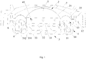
- a tweeter of this embodiment comprises a bracket 1, a diaphragm 2, a magnetic motor system 3 and a voice coil 4.
- the bracket 1 is used to support the diaphragm 2 and the magnetic motor system 3, and both the diaphragm 2 and the magnetic motor system 3 are arranged on the bracket 1.
- the diaphragm 2 comprises a top portion 21 and an edge ring 22 surrounding the top portion 21; the shape of the top portion 21 is specifically a part of the spherical shell in this embodiment, and its middle is arched upward, but it is not limited to this; the edge ring 22 extends radially outward from the edge of the top portion 21 so as to surround the top portion 21 in the circumferential direction.
- the diaphragm 2 is preferably integrally formed, that is, the top portion 21 and the edge ring 22 are integrated.
- the magnetic motor system 3 is located below the diaphragm 2 and has a magnetic gap into which the voice coil 4 is inserted.
- the upper end of the voice coil 4 is connected to the top portion 21 of the diaphragm 2 or the edge portion of the edge ring 22 close to the top portion 21, and the lower end portion thereof is inserted into the magnetic gap of the magnetic motor system 3, so as to be driven by the magnetic motor system 3 to vibrate to produce sound.
- the upper end of the voice coil 4 is preferably connected to the edge portion of the top portion 21 close to the edge ring 22. Therefore, as shown in Fig.
- a first cavity 5 is formed between the top portion 21 of the diaphragm 2, the inner wall of the voice coil 4 and the magnetic motor system 3.
- the bracket 1 is hollow to accommodate the magnetic motor system 3, the bracket 1 has an annular (including but not limited to circular, square) inner flange 11 and an annular outer flange 12, the inner flange 11 is lower than the outer flange 12, the edge ring 22 of diaphragm 2 is fixed on the outer flange 12 of the bracket 1, and the magnetic motor system 3 is fixed on the inner flange 11 of the bracket 1, so as to form a second cavity 6 between the edge ring 22 of the diaphragm 2, the outer wall of the voice coil 4 and the bracket 1.
- One or more through holes 41 are opened on the voice coil 4, and the first cavity 5 is in communication with the second cavity 6 by means of the through hole(s) 41.
- the bracket 1 has a groove 13 formed between the outer flange 12 and the inner flange 11, and the groove 13 forms a part of the second cavity 6.
- the groove 13 is an annular groove 13 surrounding the magnetic motor system 3.
- the shape of the cross-section of the groove 13 includes, but is not limited to, a rectangle, a sector, and a triangle.
- the bracket 1 is recessed downward from its portion that between the outer flange 12 and the inner flange 11 of the bracket 1 to form the groove 13, and the groove has an opening faces the fold ring 22 above.
- the bottom surface of the bracket 1 is higher than or in the same level with the bottom surface of the magnetic motor system 3.
- the damping material 14 is polyurethane foam or foamed rubber or felt.
- the above magnetic motor system 3 comprises a front plate 31, a magnetic steel 32 and a U-yoke 33 that are arranged in sequence.
- the U-yoke 33 comprises a main body 331 that is disc-shaped as a whole and an annular upper flange 332 extending upward from the main body 331, the upper flange 332 is fixedly connected to the inner flange 11 of the bracket 1, the front plate 31 and the magnetic steel 32 are arranged on the main body 331 of the U-yoke 33, and the upper flange 332 of the U-yoke 33 surrounds the front plate 31 and the magnetic steel 32 and forms the magnetic gap.
- the lower surface of the main body 331 of the U-yoke 33 is the bottom surface of the bracket 1, which is preferably in the same level with the bottom surface of the bracket 1.
- the tweeter further comprises a panel 6 covering above the diaphragm 2, and the panel 6, the edge ring 22 and the outer flange 12 of the bracket 1 are sequentially and fixedly connected.
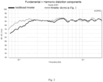
- a frequency response test was performed on the traditional tweeter and the tweeter of this embodiment, and two frequency response curves of the tweeters were obtained, as shown in Fig. 2 .
- the line with lighter color represents the frequency response curve of the tweeter of Embodiment 1
- the line with darker color represents the frequency response curve of the ordinary tweeter.
- the F0 (resonance frequency) of the tweeter of this embodiment is 1200 Hz
- the F0 (resonance frequency) of the traditional tweeter is 1580 Hz.
- the speaker extends more towards the low frequency part
- the frequency response curve of the tweeter shown in Fig. 1 extends more to the low frequency range than the traditional tweeter.
- the air-gap cavity of the tweeter is enlarged, so that the F0 (loudspeaker resonance frequency) of the tweeter is reduced, so that the intermediate frequency range of the tweeter extends further forward, thereby widening the starting frequency of the tweeter, and it can be better converged with the mid-bass loudspeaker in actual use; by adding the damping material 14 in the second cavity 6, the Q (Quality Factor) value of the tweeter is lowered to smooth the mid-frequency curve of the tweeter, reduce the distortion of the tweeter, and improve the sound quality.
- the size of the tweeter is relatively small and the assembly is relatively simple, especially the increase in the overall size (especially the thickness) of the loudspeaker is avoided, and the applicable scenarios are wider.
- the automobile audio system comprises a tweeter 100 and a woofer 200, which does not include a mid-range loudspeaker.
- the automobile audio system may further comprise a subwoofer.
- the tweeter 100 adopts the tweeter shown in Fig. 1 , so it can be well matched with the woofer 200, and can be well converged in the mid-frequency range, and even without a mid-range loudspeaker, it can produce better sound effects.
Landscapes
- Physics & Mathematics (AREA)
- Engineering & Computer Science (AREA)
- Acoustics & Sound (AREA)
- Signal Processing (AREA)
- Health & Medical Sciences (AREA)
- Otolaryngology (AREA)
- Audible-Bandwidth Dynamoelectric Transducers Other Than Pickups (AREA)
- Obtaining Desirable Characteristics In Audible-Bandwidth Transducers (AREA)
- Soundproofing, Sound Blocking, And Sound Damping (AREA)
Applications Claiming Priority (2)
| Application Number | Priority Date | Filing Date | Title |
|---|---|---|---|
| CN202010338269.6A CN111629306B (zh) | 2020-04-26 | 2020-04-26 | 一种高音扬声器 |
| PCT/CN2021/089622 WO2021218856A1 (fr) | 2020-04-26 | 2021-04-25 | Haut-parleur d'aigus et système audio d'automobile |
Publications (2)
| Publication Number | Publication Date |
|---|---|
| EP4132003A1 true EP4132003A1 (fr) | 2023-02-08 |
| EP4132003A4 EP4132003A4 (fr) | 2023-09-06 |
Family
ID=72260562
Family Applications (1)
| Application Number | Title | Priority Date | Filing Date |
|---|---|---|---|
| EP21797148.0A Pending EP4132003A4 (fr) | 2020-04-26 | 2021-04-25 | Haut-parleur d'aigus et système audio d'automobile |
Country Status (5)
| Country | Link |
|---|---|
| US (1) | US12294847B2 (fr) |
| EP (1) | EP4132003A4 (fr) |
| JP (1) | JP2023523055A (fr) |
| CN (1) | CN111629306B (fr) |
| WO (1) | WO2021218856A1 (fr) |
Families Citing this family (4)
| Publication number | Priority date | Publication date | Assignee | Title |
|---|---|---|---|---|
| CN111629306B (zh) * | 2020-04-26 | 2024-06-14 | 苏州上声电子股份有限公司 | 一种高音扬声器 |
| CN221961957U (zh) * | 2024-02-26 | 2024-11-05 | 国光电器股份有限公司 | 高音扬声器 |
| CN118945569A (zh) * | 2024-08-07 | 2024-11-12 | 苏州上声电子股份有限公司 | 一种扩散罩及高音扬声器 |
| CN120034802B (zh) * | 2025-02-18 | 2025-09-09 | 东莞市瑞达声学科技有限公司 | 一种音圈水平偏差纠正的扬声器 |
Family Cites Families (26)
| Publication number | Priority date | Publication date | Assignee | Title |
|---|---|---|---|---|
| JPS6036951Y2 (ja) * | 1980-04-01 | 1985-11-01 | ソニー株式会社 | スピ−カユニツト |
| JPS6216068Y2 (fr) * | 1981-03-28 | 1987-04-23 | ||
| JPS6033147A (ja) * | 1983-07-30 | 1985-02-20 | Nissan Motor Co Ltd | 車両用音響装置の保護構造 |
| JPS63278490A (ja) * | 1987-05-08 | 1988-11-16 | Matsushita Electric Ind Co Ltd | 動電型ユニット |
| JPH02312397A (ja) * | 1989-05-26 | 1990-12-27 | Matsushita Electric Ind Co Ltd | スピーカ |
| JP2673026B2 (ja) * | 1990-01-11 | 1997-11-05 | 株式会社ケンウッド | スピーカの配線構造 |
| JPH0528199U (ja) * | 1991-03-11 | 1993-04-09 | オンキヨー株式会社 | 薄形ドーム型スピーカ |
| US20050286729A1 (en) * | 1999-07-23 | 2005-12-29 | George Harwood | Flat speaker with a flat membrane diaphragm |
| JP4147311B2 (ja) * | 2001-03-21 | 2008-09-10 | オンキヨー株式会社 | スピーカー |
| JP2005277874A (ja) * | 2004-03-25 | 2005-10-06 | Pioneer Electronic Corp | 同軸スピーカー装置及びその製造方法 |
| DE102006021552A1 (de) * | 2006-05-08 | 2007-11-15 | Robert Bosch Gmbh | Kalotten-Lautsprecher |
| US7831059B1 (en) * | 2006-11-03 | 2010-11-09 | Sahyoun Joseph Y | Self-cooled electro-magnetic audio transducer |
| CN102577435A (zh) * | 2009-10-15 | 2012-07-11 | 日本先锋公司 | 扬声器装置 |
| CN202979242U (zh) * | 2012-11-29 | 2013-06-05 | 郁志曰 | 一种空气动力振动喇叭驱动单元及其头戴式耳机 |
| CN106331962B (zh) * | 2016-09-30 | 2021-01-29 | 海信视像科技股份有限公司 | 一种扬声器 |
| CN106412774A (zh) * | 2016-10-11 | 2017-02-15 | 歌尔科技有限公司 | 一种扬声器振膜以及扬声器 |
| US10368159B2 (en) * | 2016-12-28 | 2019-07-30 | Mitek Corp., Inc. | Water resistant loudspeaker |
| US20190253806A1 (en) * | 2018-02-15 | 2019-08-15 | Alexander B. RALPH | Ported tweeter |
| CN208158876U (zh) | 2018-05-14 | 2018-11-27 | 苏州上声电子股份有限公司 | 一种高音扬声器 |
| CN108347679B (zh) * | 2018-05-14 | 2020-11-20 | 苏州上声电子股份有限公司 | 一种高音扬声器 |
| CN208675521U (zh) * | 2018-07-30 | 2019-03-29 | 常州阿木奇声学科技有限公司 | 双动圈扬声器 |
| CN109862490B (zh) * | 2018-12-30 | 2021-07-09 | 瑞声声学科技(深圳)有限公司 | 扬声器 |
| CN110035361B (zh) * | 2019-05-22 | 2024-04-23 | 东莞市雷凯仕电子科技有限公司 | 超薄扬声器 |
| CN210899588U (zh) * | 2019-11-29 | 2020-06-30 | 深圳市天泽扬声器有限公司 | 一种可降低低频频率范围的内磁球顶扬声器 |
| CN211792023U (zh) * | 2020-04-26 | 2020-10-27 | 苏州上声电子股份有限公司 | 一种高音扬声器 |
| CN111629306B (zh) * | 2020-04-26 | 2024-06-14 | 苏州上声电子股份有限公司 | 一种高音扬声器 |
-
2020
- 2020-04-26 CN CN202010338269.6A patent/CN111629306B/zh active Active
-
2021
- 2021-04-25 WO PCT/CN2021/089622 patent/WO2021218856A1/fr not_active Ceased
- 2021-04-25 EP EP21797148.0A patent/EP4132003A4/fr active Pending
- 2021-04-25 US US17/997,062 patent/US12294847B2/en active Active
- 2021-04-25 JP JP2022564672A patent/JP2023523055A/ja active Pending
Also Published As
| Publication number | Publication date |
|---|---|
| US12294847B2 (en) | 2025-05-06 |
| US20230179924A1 (en) | 2023-06-08 |
| EP4132003A4 (fr) | 2023-09-06 |
| WO2021218856A1 (fr) | 2021-11-04 |
| JP2023523055A (ja) | 2023-06-01 |
| CN111629306A (zh) | 2020-09-04 |
| CN111629306B (zh) | 2024-06-14 |
Similar Documents
| Publication | Publication Date | Title |
|---|---|---|
| EP4132003A1 (fr) | Haut-parleur d'aigus et système audio d'automobile | |
| EP3383060B1 (fr) | Dispositif de haut-parleur | |
| JP4610890B2 (ja) | スピーカ装置 | |
| US10299035B2 (en) | Acoustic lens system for loudspeakers | |
| EP3734991A1 (fr) | Haut-parleur, système de haut-parleur, système de haut-parleur stéréo et système de haut-parleur stéréo embarqué | |
| US11363366B2 (en) | Headphone device | |
| JP2965978B2 (ja) | スピーカ装置 | |
| JP2020182041A (ja) | 電気音響変換器 | |
| JP7310970B2 (ja) | スピーカ | |
| EP3449642B1 (fr) | Tube basse reflex pour haut-parleur | |
| CN108347679A (zh) | 一种高音扬声器 | |
| JP2010034988A (ja) | スピーカ装置 | |
| EP4280626A1 (fr) | Haut-parleur et système audio | |
| CN213960312U (zh) | 一种扬声器及音响系统 | |
| CN211792023U (zh) | 一种高音扬声器 | |
| US9241210B1 (en) | Mass ports for tuning driver frequency response | |
| US20210204063A1 (en) | Drum paper and loudspeaker having improved surround element and reduced sound distortion | |
| CN115769600A (zh) | 电声换能器 | |
| JP2009164676A (ja) | パッシブラジエータ | |
| EP3503585A1 (fr) | Système de haut-parleur de véhicule et système audio | |
| JP6989751B2 (ja) | ダストキャップおよびこれを用いる動電型スピーカー | |
| CN219728048U (zh) | 座椅和具有其的车辆 | |
| JP3479994B2 (ja) | スピーカ | |
| JP2008306639A (ja) | ヘッドホンユニット、及びヘッドホン | |
| WO2009122573A1 (fr) | Dispositif de haut-parleur |
Legal Events
| Date | Code | Title | Description |
|---|---|---|---|
| STAA | Information on the status of an ep patent application or granted ep patent |
Free format text: STATUS: THE INTERNATIONAL PUBLICATION HAS BEEN MADE |
|
| PUAI | Public reference made under article 153(3) epc to a published international application that has entered the european phase |
Free format text: ORIGINAL CODE: 0009012 |
|
| STAA | Information on the status of an ep patent application or granted ep patent |
Free format text: STATUS: REQUEST FOR EXAMINATION WAS MADE |
|
| 17P | Request for examination filed |
Effective date: 20221102 |
|
| AK | Designated contracting states |
Kind code of ref document: A1 Designated state(s): AL AT BE BG CH CY CZ DE DK EE ES FI FR GB GR HR HU IE IS IT LI LT LU LV MC MK MT NL NO PL PT RO RS SE SI SK SM TR |
|
| DAV | Request for validation of the european patent (deleted) | ||
| DAX | Request for extension of the european patent (deleted) | ||
| A4 | Supplementary search report drawn up and despatched |
Effective date: 20230807 |
|
| RIC1 | Information provided on ipc code assigned before grant |
Ipc: H04R 7/12 20060101ALN20230801BHEP Ipc: H04R 1/02 20060101ALI20230801BHEP Ipc: H04R 1/28 20060101ALI20230801BHEP Ipc: H04R 9/06 20060101ALI20230801BHEP Ipc: H04R 9/04 20060101ALI20230801BHEP Ipc: H04R 9/02 20060101AFI20230801BHEP |
|
| STAA | Information on the status of an ep patent application or granted ep patent |
Free format text: STATUS: EXAMINATION IS IN PROGRESS |
|
| 17Q | First examination report despatched |
Effective date: 20250617 |