EP4131918A1 - Elektronische vorrichtung - Google Patents
Elektronische vorrichtung Download PDFInfo
- Publication number
- EP4131918A1 EP4131918A1 EP21780871.6A EP21780871A EP4131918A1 EP 4131918 A1 EP4131918 A1 EP 4131918A1 EP 21780871 A EP21780871 A EP 21780871A EP 4131918 A1 EP4131918 A1 EP 4131918A1
- Authority
- EP
- European Patent Office
- Prior art keywords
- camera
- mounting
- display screen
- electronic device
- frame
- Prior art date
- Legal status (The legal status is an assumption and is not a legal conclusion. Google has not performed a legal analysis and makes no representation as to the accuracy of the status listed.)
- Pending
Links
Images

Classifications
-
- H—ELECTRICITY
- H04—ELECTRIC COMMUNICATION TECHNIQUE
- H04M—TELEPHONIC COMMUNICATION
- H04M1/00—Substation equipment, e.g. for use by subscribers
- H04M1/02—Constructional features of telephone sets
- H04M1/0202—Portable telephone sets, e.g. cordless phones, mobile phones or bar type handsets
- H04M1/026—Details of the structure or mounting of specific components
- H04M1/0264—Details of the structure or mounting of specific components for a camera module assembly
-
- H—ELECTRICITY
- H04—ELECTRIC COMMUNICATION TECHNIQUE
- H04N—PICTORIAL COMMUNICATION, e.g. TELEVISION
- H04N23/00—Cameras or camera modules comprising electronic image sensors; Control thereof
- H04N23/57—Mechanical or electrical details of cameras or camera modules specially adapted for being embedded in other devices
-
- H—ELECTRICITY
- H04—ELECTRIC COMMUNICATION TECHNIQUE
- H04N—PICTORIAL COMMUNICATION, e.g. TELEVISION
- H04N23/00—Cameras or camera modules comprising electronic image sensors; Control thereof
- H04N23/50—Constructional details
-
- H—ELECTRICITY
- H04—ELECTRIC COMMUNICATION TECHNIQUE
- H04N—PICTORIAL COMMUNICATION, e.g. TELEVISION
- H04N23/00—Cameras or camera modules comprising electronic image sensors; Control thereof
- H04N23/50—Constructional details
- H04N23/54—Mounting of pick-up tubes, electronic image sensors, deviation or focusing coils
-
- H—ELECTRICITY
- H04—ELECTRIC COMMUNICATION TECHNIQUE
- H04M—TELEPHONIC COMMUNICATION
- H04M1/00—Substation equipment, e.g. for use by subscribers
- H04M1/02—Constructional features of telephone sets
- H04M1/0202—Portable telephone sets, e.g. cordless phones, mobile phones or bar type handsets
- H04M1/026—Details of the structure or mounting of specific components
- H04M1/0266—Details of the structure or mounting of specific components for a display module assembly
Definitions
- the present invention relates to the field of communication device technologies, and in particular, to an electronic device.
- a retractable camera As users have extremely high requirements for functions and appearances of electronic devices, increasing a ratio of a display screen has become a development trend. For example, a retractable camera is adopted. However, the retractable camera has relatively high costs. Therefore, pole-screen electronic devices have become a mainstream.
- a viewing aperture on the display screen needs to be reduced. Once the viewing aperture is reduced, the resolving power of a camera when being stressed is degraded, resulting in cracking of the display screen. Therefore, it is difficult to increase the display ratio while reducing the viewing aperture on the display screen.
- the present invention discloses an electronic device, to resolve the problem that for an existing electronic device, it is difficult to increase a display ratio while reducing a viewing aperture on a display screen.
- An electronic device including a housing, a display screen, a mainboard support, and a camera.
- a first mounting portion is arranged on the housing.
- the display screen is mounted on the housing, a mounting cavity is formed between the display screen and the housing, and the display screen has a light-transmitting hole.
- the mainboard support is mounted on the housing, located inside the mounting cavity, and arranged spaced apart from the display screen.
- a second mounting portion is arranged on the mainboard support.
- the camera is located inside the mounting cavity, is arranged facing the light-transmitting hole, and matches the first mounting portion and the second mounting portion respectively, to be positioned between the housing and the mainboard support.
- a distance between the camera and the display screen satisfies: 0.15 mm ⁇ n ⁇ 0.4 mm.
- the first mounting portion is arranged on the housing
- the second mounting portion is arranged on a mainboard support
- the camera matches the first mounting portion and the second mounting portion respectively, so that the camera is positioned between the housing and the mainboard support, which can improve the power of the camera in the pole-screen electronic device in resolving an external force when the camera is stressed and reduce the probability of cracking of the display screen.
- the distance between the camera and the display screen is set to a range of 0.15 mm to 0.4 mm, which can reduce a light-transmitting hole on the display screen and increase the display ratio, thereby resolving the problem that it is difficult to increase the display ratio while reducing a viewing aperture on the display screen.
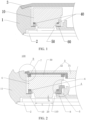
- a pole-screen electronic device in the related art is first described below with reference to FIG. 1 .
- FIG. 1 is a partial cross-sectional view of a pole-screen electronic device in the related art.
- the pole-screen electronic device mainly includes a housing 1, a display screen 2, a back cover 3, a camera 10, and a camera support 50.
- the camera support 50 is fixed on the housing 1 by using a support glue 60, the camera 10 is assembled and fixed on the camera support 50 by using foam 40, and the back cover 3 provides support at the bottom of the camera 10.
- a relatively large distance (generally greater than 5 mm) is generally reserved between the camera 10 and the display screen 2, resulting in a relatively large opening of screen printing (that is, a viewing aperture of the camera), which may reduce a display ratio, that is, reduce a display ratio of the display screen.
- the pole-screen electronic device in the related art has the problem that it is difficult to increase the display ratio while reducing the viewing aperture on the display screen.
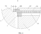
- an electronic device 100 includes: a housing, a display screen 2, a mainboard support 3, and a camera 4.
- a first mounting portion 10 is arranged on the housing.
- the display screen 2 is mounted on the housing, a mounting cavity is formed between the display screen 2 and the housing, and the display screen 2 has a light-transmitting hole 20.
- the mainboard support 3 is mounted on the housing, located inside the mounting cavity, and arranged spaced apart from the display screen 2.
- a second mounting portion 30 is arranged on the mainboard support 3.
- the camera 4 is located inside the mounting cavity, is arranged facing the light-transmitting hole 20, and matches the first mounting portion 10 and the second mounting portion 30 respectively to be positioned between the housing and the mainboard support 3.
- the light-transmitting hole 20 is used as a viewing aperture of the camera 4.
- a distance n between the camera 4 and the display screen 2 satisfies: 0.15 mm ⁇ n ⁇ 0.4 mm. That is, the distance n between the camera 4 and the display screen 2 may be set to any value in a range of 0.15 mm to 0.4 mm, for example, 0.15 mm, 0.2 mm, 0.3 mm, and 0.38 mm.
- the first mounting portion 10 is arranged on the housing
- the second mounting portion 30 is arranged on the mainboard support 3
- the camera 4 matches the first mounting portion 10 and the second mounting portion 30 respectively, so that the camera 4 is positioned between the housing and the mainboard support 3, which can improve the power of the camera 4 in the pole-screen electronic device 100 in resolving an external force when the camera 4 is stressed, and reduce the probability of cracking of the display screen 2.
- the distance between the camera 4 and the display screen 2 is set to a range of 0.15 mm to 0.4 mm, which, on the one hand, can reduce the light-transmitting hole 20 on the display screen 2 and increase the display ratio of the display screen 2, and on the other hand, can make the camera 4 keep some resolving power after the camera 4 is stressed, thereby resolving the problem that it is difficult to increase the display ratio while reducing the viewing aperture on the display screen 2.
- a maximum diameter L of the light-transmitting hole 20 satisfies: L ⁇ 10 mm. That is, the diameter of the light-transmitting hole 20 may be 9 mm, 8 mm, 8.5 mm, or the like. As described above, by reducing a minimum distance between the camera 4 and the display screen 2, an imaging angle requirement of the camera 4 can be met by a light-transmitting hole 20 with a relatively small size, thereby reducing the light-transmitting hole 20 and increasing the display ratio of the display screen 2.
- the electronic device 100 further includes a first buffer member 6.
- the first buffer member 6 is connected between the camera 4 and the first mounting portion 10.
- the first buffer member 6 may provide a buffering effect for the camera 4, to improve the power of the camera 4 in resolving the force, thereby avoiding damage and improving reliability.
- the first buffer member 6 may be a flexible member such as foam or soft rubber. Therefore, the first buffer member 6 can provide buffering through its own elastic deformation with low costs and a good buffering effect.
- the housing includes a frame 11.
- the display screen 2 is mounted at a first end (that is, a lower end shown in the figure) in a thickness direction of the frame 11.
- the first mounting portion 10 is located inside the mounting cavity, connected to the frame 11, arranged adjacent to the display screen 2, and provided with a first mounting through hole 110.
- the camera 4 penetrates through the first mounting through hole 110 and corresponds to the light-transmitting hole 20.
- the first buffer member 6 is located on a side of the first mounting portion 10 away from the display screen 2. Therefore, a size of the electronic device 100 in the thickness direction may be reduced.
- that the camera 4 extends into the first mounting through hole 110 can improve the assembly stability and enhance the power of the camera 4 in resolving a force when the camera 4 is stressed.
- the housing further includes a back cover (not shown in the figure).
- the back cover is connected to the frame 11, and matches both the frame 11 and the display screen 2 to form the mounting cavity. In this way, the mounting cavity may be sealed by the back cover, thereby providing protection for internal devices.
- the electronic device 100 further includes a camera support 5.
- the camera support 5 is sleeved on the camera 4, connected to the first mounting portion 10, and provided with a second mounting through hole 50.
- the camera 4 penetrates through the second mounting through hole 50.
- the first buffer member 6 is connected between the camera 4 and the camera support 5. Therefore, the camera support 5 can provide support and protection for the camera 4. Arranging the first buffer member 6 between the camera 4 and the camera support 5 not only can provide a better buffering effect for the camera 4, but also can facilitate assembly, thereby reducing an assembly time and costs.
- the camera support 5 includes a first carrying portion 51, a second carrying portion 52, and a connecting section 53.
- first carrying portion 51 In the thickness direction of the frame 11, one end of the first carrying portion 51 is connected to the first mounting portion 10, and an other end of the first carrying portion 51 is connected to the first buffer member 6.
- the second carrying portion 52 is located on a side of the camera 4 away from the frame 11 and located, in the thickness direction of the frame 11, on a side of the first carrying portion 51 away from the display screen 2.
- the first mounting portion 10 is abutted against one end of the second carrying portion 52, and the camera 4 is abutted against an other end of the second carrying portion 52.
- the connecting section 53 is located between the first carrying portion 51 and the second carrying portion 52.
- One end of the connecting section 53 is connected to a radially outer end of the first carrying portion 51, and an other end of the connecting section 53 is connected to the second carrying portion 52.
- the first carrying portion 51 is connected to the camera 4 and the first mounting portion 10.
- the first carrying portion is adhered and connected to the first mounting portion 10 by using a connecting glue 8.
- the connecting section 53 is connected to the first carrying portion 51 and the second carrying portion 52.
- the first carrying portion 51 and the connecting section 53 jointly form an assembly step, and the camera 4 is connected to the assembly step by the first buffer member 6 to implement positioning.
- the second carrying portion 52 is connected to the camera.
- the second carrying portion 52 and the connecting section 53 jointly form an assembly step, and the camera 4 is abutted against the assembly step to implement positioning.
- the arrangement of the two assembly steps may provide support for the camera 4 at two positions.
- a combination of the first buffer member 6 and one assembly step can provide a buffered supporting force for the camera 4, so that the camera 4 has a better analyzing power when being stressed, thereby greatly reducing the probability of damage to the camera 4 and cracking of the display screen 2, thereby improving the reliability.
- the first buffer member 6 is ring-shaped.
- the first carrying portion 51 is constructed as an annular carrying portion, and a size m of the second carrying portion 52 in the thickness direction of the frame 11 satisfies: m ⁇ 0.3 mm.
- the first buffer member 6 may provide buffering and support for the camera 4 in the entire circumferential direction.
- the size of the second carrying portion 52 in the thickness direction of the frame 11 is at least 0.3 mm, that is, the thickness of the skirt of the camera support 5 is 0.3 mm and above. Therefore, the strength of the second carrying portion 52 may be enhanced, to improve the carrying capability of the second carrying portion 52 and provide reliable support for the camera 4, thereby improving the reliability and stability.
- the thickness of the second carrying portion 52 may be 0.3 mm, 0.4 mm, 0.45 mm, or the like.
- a person skilled in the art may set the thickness by comprehensively considering factors such as a carrying requirement, a spatial layout, and costs, which are not specifically limited in the present invention.
- the electronic device 100 further includes a second buffer member 7.
- the second buffer member 7 is connected between the camera 4 and the second mounting portion 30. Therefore, when the electronic device 100 is subject to an external force, the second buffer member 7 may provide a buffering effect for the camera 4 at another angle, to improve the power of the camera 4 in resolving the force, thereby further improving the reliability.
- the first buffer member 6 may be a flexible member such as foam or soft rubber.
- the first buffer member 6 may provide buffering through its own deformation.
- the second buffer member 7 may also be a flexible member such as foam or soft rubber.
- the second buffer member 7 can provide buffering through its own deformation with low costs and a good buffering effect.
- the mainboard support 3 includes a main support 31 and a mounting support 32.
- the mounting support 32 is connected to a side of the main support 31 adjacent to the frame 11, connected to the frame 11, and provided with a mounting groove on a side facing the camera 4.
- the mounting groove forms the second mounting portion 30.
- the camera 4 can be mounted inside the mounting groove, and the mounting groove is used to provide support for the camera 4, which, on the one hand, can improve the stability and reliability of the camera 4, and on the other hand, can reduce a space occupied by the mounting cavity, thereby preventing the overall thickness of the electronic device 100 from being greatly affected.
- the mounting support 32 includes a connecting portion 321 and a supporting portion 322.
- the connecting portion 321 is connected to the main support 31.
- the supporting portion 322 is connected to a side of the connecting portion 321 adjacent to the camera 4 and is connected to the frame 11 and the camera 4 respectively.
- the connection between the mounting support 32 and the frame 11 can improve the stability of the camera 4 to some extent and reduce impact on the camera 4 when the electronic device 100 is subject to an external force, thereby further reducing the probability of damage to and cracking of the camera 4 and display screen 2.
- a second end of the frame 11 in the thickness direction is provided with a sink 111.
- the supporting portion 322 has a boss 323, and the boss 323 is abutted against and matches the sink 111. Therefore, the mounting support 32 may be connected to the frame 11, which is convenient for processing and assembly, and provides high reliability. It may be understood that there may be a plurality of sets of bosses 323 and sinks 111 in a one-to-one correspondence, thereby providing better support and protection for the camera 4.
- the supporting portion 322 may optionally be a metal member.
- the connecting portion 321 may optionally be a plastic member.
- the supporting portion 322 may be connected to the connecting portion 321 in an injection-molding manner.
- a size a by which the boss 323 extends into the sink 111 satisfies: a ⁇ 0.25 mm.
- the supporting portion 322 is a metal plastic injection-molded member.
- the boss 323 overlaps with the sink 111.
- the size by which the boss 323 extends into the sink 111 is at least 0.25 mm.
- the boss 323 may extend into the sink 111 by 0.25 mm, 0.3 mm, 0.4 mm, or the like, which can improve the strength of the mounting support 32 while allowing the boss 323 and the sink 111 to have some manufacturing errors, thereby reducing the costs.
- the distance between the camera 4 and the display screen 2 can be reduced.
- the camera 4 is supported by the skirt of the camera support 5.
- the camera support 5, the first buffer member 6, and the second buffer member 7 are configured to provide buffering.
- the mainboard support 3 is lapped on the sink 111 by using the boss 323.
- the camera 4 is mounted inside the mounting groove, to provide support and protection for the camera 4, so that the power of the camera 4 in resolving an external force is improved when the camera 4 is stressed, and problems of cracking of the display screen 2 and degradation of the resolving power of the front-facing camera are resolved, to reduce the size of the viewing aperture on the display screen 2 while increasing the display ratio, thereby providing a better user experience.
Landscapes
- Engineering & Computer Science (AREA)
- Signal Processing (AREA)
- Multimedia (AREA)
- Studio Devices (AREA)
- Casings For Electric Apparatus (AREA)
- Telephone Set Structure (AREA)
Applications Claiming Priority (2)
| Application Number | Priority Date | Filing Date | Title |
|---|---|---|---|
| CN202010239683.1A CN111432101B (zh) | 2020-03-30 | 2020-03-30 | 电子设备 |
| PCT/CN2021/083906 WO2021197312A1 (zh) | 2020-03-30 | 2021-03-30 | 电子设备 |
Publications (2)
| Publication Number | Publication Date |
|---|---|
| EP4131918A1 true EP4131918A1 (de) | 2023-02-08 |
| EP4131918A4 EP4131918A4 (de) | 2023-09-20 |
Family
ID=71550305
Family Applications (1)
| Application Number | Title | Priority Date | Filing Date |
|---|---|---|---|
| EP21780871.6A Pending EP4131918A4 (de) | 2020-03-30 | 2021-03-30 | Elektronische vorrichtung |
Country Status (6)
| Country | Link |
|---|---|
| US (1) | US12598370B2 (de) |
| EP (1) | EP4131918A4 (de) |
| JP (1) | JP7457147B2 (de) |
| KR (1) | KR102752028B1 (de) |
| CN (1) | CN111432101B (de) |
| WO (1) | WO2021197312A1 (de) |
Families Citing this family (4)
| Publication number | Priority date | Publication date | Assignee | Title |
|---|---|---|---|---|
| CN111432101B (zh) * | 2020-03-30 | 2021-09-10 | 维沃移动通信有限公司 | 电子设备 |
| CN112532829A (zh) * | 2020-11-18 | 2021-03-19 | 深圳市海洋王照明工程有限公司 | 摄像照明装置 |
| CN113489875A (zh) * | 2021-07-23 | 2021-10-08 | 维沃移动通信有限公司 | 电子设备 |
| WO2026084316A1 (ko) * | 2024-10-20 | 2026-04-23 | 삼성전자주식회사 | 카메라를 포함하는 전자 장치 |
Family Cites Families (16)
| Publication number | Priority date | Publication date | Assignee | Title |
|---|---|---|---|---|
| JP2007028544A (ja) * | 2005-07-21 | 2007-02-01 | Matsushita Electric Works Ltd | インターホン装置 |
| CN105554352A (zh) * | 2015-11-27 | 2016-05-04 | 小米科技有限责任公司 | 摄像头模组和电子设备 |
| KR102502894B1 (ko) * | 2018-05-02 | 2023-02-24 | 삼성전자주식회사 | 평면부를 포함하는 윈도우 글래스의 제조 방법 및 상기 윈도우 글래스를 포함하는 전자 장치 |
| CN208110687U9 (zh) * | 2018-05-09 | 2018-12-11 | 深圳市鑫华锋科技有限公司 | 一种行车记录仪 |
| KR102036204B1 (ko) * | 2018-06-18 | 2019-10-24 | 양경호 | 휴대형 이동통신 단말기의 자기 영상 촬영장치 및 그 제어 방법 |
| CN209151206U (zh) * | 2019-01-28 | 2019-07-23 | 珠海市魅族科技有限公司 | 一种移动终端及其中框 |
| CN209823798U (zh) * | 2019-03-19 | 2019-12-20 | Oppo广东移动通信有限公司 | 电子设备、显示屏组件和盖板 |
| CN209313933U (zh) * | 2019-03-19 | 2019-08-27 | Oppo广东移动通信有限公司 | 一种摄像头以及终端设备 |
| CN210137339U (zh) * | 2019-03-19 | 2020-03-10 | Oppo广东移动通信有限公司 | 电子设备 |
| CN110049161B (zh) * | 2019-05-06 | 2021-01-15 | 维沃移动通信有限公司 | 移动终端 |
| CN110072060B (zh) * | 2019-05-31 | 2021-11-16 | 维沃移动通信(杭州)有限公司 | 终端设备及其控制方法和控制装置、计算机可读存储介质 |
| CN110191272B (zh) * | 2019-06-28 | 2024-06-07 | Oppo广东移动通信有限公司 | 摄像头组件及电子设备 |
| CN209964150U (zh) * | 2019-06-28 | 2020-01-17 | Oppo广东移动通信有限公司 | 摄像头组件及电子设备 |
| KR102713222B1 (ko) * | 2019-09-06 | 2024-10-07 | 삼성전자 주식회사 | 카메라 모듈을 포함하는 전자 장치 |
| CN110769095B (zh) * | 2019-10-16 | 2022-05-20 | Oppo广东移动通信有限公司 | 电子设备的屏幕组件及电子设备 |
| CN111432101B (zh) * | 2020-03-30 | 2021-09-10 | 维沃移动通信有限公司 | 电子设备 |
-
2020
- 2020-03-30 CN CN202010239683.1A patent/CN111432101B/zh active Active
-
2021
- 2021-03-30 EP EP21780871.6A patent/EP4131918A4/de active Pending
- 2021-03-30 WO PCT/CN2021/083906 patent/WO2021197312A1/zh not_active Ceased
- 2021-03-30 JP JP2022552378A patent/JP7457147B2/ja active Active
- 2021-03-30 KR KR1020227036154A patent/KR102752028B1/ko active Active
-
2022
- 2022-09-29 US US17/956,610 patent/US12598370B2/en active Active
Also Published As
| Publication number | Publication date |
|---|---|
| US12598370B2 (en) | 2026-04-07 |
| JP2023515861A (ja) | 2023-04-14 |
| WO2021197312A1 (zh) | 2021-10-07 |
| US20230022679A1 (en) | 2023-01-26 |
| JP7457147B2 (ja) | 2024-03-27 |
| KR20220155366A (ko) | 2022-11-22 |
| CN111432101A (zh) | 2020-07-17 |
| KR102752028B1 (ko) | 2025-01-10 |
| EP4131918A4 (de) | 2023-09-20 |
| CN111432101B (zh) | 2021-09-10 |
Similar Documents
| Publication | Publication Date | Title |
|---|---|---|
| US12598370B2 (en) | Electronic device | |
| US10171896B2 (en) | Electronic device with side speaker hole | |
| US11012766B2 (en) | Electronic device including speaker module | |
| US12341917B2 (en) | Foldable electronic device comprising elastic means | |
| EP3930296B1 (de) | Mobiles endgerät und mittelrahmen | |
| US8457487B2 (en) | Camera assembly and portable electronic device | |
| CN101699829B (zh) | 一种移动终端的扬声器座 | |
| CN209982520U (zh) | 一种移动终端 | |
| EP3606022A1 (de) | Doppelkameramodulanordnung und mobiles endgerät | |
| CN111614800A (zh) | 一种移动终端 | |
| EP3606023A1 (de) | Doppelkameramodulanordnung und mobiles endgerät | |
| WO2022135324A1 (zh) | 摄像模组及电子设备 | |
| CN110049161A (zh) | 移动终端 | |
| CN110166602A (zh) | 电子设备 | |
| CN209964150U (zh) | 摄像头组件及电子设备 | |
| EP3829193B1 (de) | Schallemissionsstruktur und endgerät | |
| US11528543B2 (en) | Terminal device and sound-emitting apparatus | |
| US11973528B2 (en) | Protective case for portable electronic device | |
| CN209964153U (zh) | 电子设备 | |
| WO2020014821A1 (zh) | 电子设备 | |
| CN209787210U (zh) | 移动终端和手机中框 | |
| CN209515166U (zh) | 终端设备 | |
| WO2022105307A1 (zh) | 电子设备 | |
| CN209964155U (zh) | 电子设备 | |
| CN112385202B (zh) | 电子设备 |
Legal Events
| Date | Code | Title | Description |
|---|---|---|---|
| STAA | Information on the status of an ep patent application or granted ep patent |
Free format text: STATUS: THE INTERNATIONAL PUBLICATION HAS BEEN MADE |
|
| PUAI | Public reference made under article 153(3) epc to a published international application that has entered the european phase |
Free format text: ORIGINAL CODE: 0009012 |
|
| STAA | Information on the status of an ep patent application or granted ep patent |
Free format text: STATUS: REQUEST FOR EXAMINATION WAS MADE |
|
| 17P | Request for examination filed |
Effective date: 20221026 |
|
| AK | Designated contracting states |
Kind code of ref document: A1 Designated state(s): AL AT BE BG CH CY CZ DE DK EE ES FI FR GB GR HR HU IE IS IT LI LT LU LV MC MK MT NL NO PL PT RO RS SE SI SK SM TR |
|
| DAV | Request for validation of the european patent (deleted) | ||
| DAX | Request for extension of the european patent (deleted) | ||
| REG | Reference to a national code |
Ref country code: DE Ref legal event code: R079 Free format text: PREVIOUS MAIN CLASS: H04N0005225000 Ipc: H04M0001020000 |
|
| A4 | Supplementary search report drawn up and despatched |
Effective date: 20230823 |
|
| RIC1 | Information provided on ipc code assigned before grant |
Ipc: H04M 1/02 20060101AFI20230817BHEP |
|
| STAA | Information on the status of an ep patent application or granted ep patent |
Free format text: STATUS: EXAMINATION IS IN PROGRESS |
|
| 17Q | First examination report despatched |
Effective date: 20251209 |