EP4130894B1 - Physikalisches gehäuse für optische gitteruhr - Google Patents
Physikalisches gehäuse für optische gitteruhr Download PDFInfo
- Publication number
- EP4130894B1 EP4130894B1 EP21780468.1A EP21780468A EP4130894B1 EP 4130894 B1 EP4130894 B1 EP 4130894B1 EP 21780468 A EP21780468 A EP 21780468A EP 4130894 B1 EP4130894 B1 EP 4130894B1
- Authority
- EP
- European Patent Office
- Prior art keywords
- coil
- magnetic field
- mot
- axis
- optical
- Prior art date
- Legal status (The legal status is an assumption and is not a legal conclusion. Google has not performed a legal analysis and makes no representation as to the accuracy of the status listed.)
- Active
Links
Images


Classifications
-
- G—PHYSICS
- G04—HOROLOGY
- G04F—TIME-INTERVAL MEASURING
- G04F5/00—Apparatus for producing preselected time intervals for use as timing standards
- G04F5/14—Apparatus for producing preselected time intervals for use as timing standards using atomic clocks
-
- G—PHYSICS
- G02—OPTICS
- G02F—OPTICAL DEVICES OR ARRANGEMENTS FOR THE CONTROL OF LIGHT BY MODIFICATION OF THE OPTICAL PROPERTIES OF THE MEDIA OF THE ELEMENTS INVOLVED THEREIN; NON-LINEAR OPTICS; FREQUENCY-CHANGING OF LIGHT; OPTICAL LOGIC ELEMENTS; OPTICAL ANALOGUE/DIGITAL CONVERTERS
- G02F1/00—Devices or arrangements for the control of the intensity, colour, phase, polarisation or direction of light arriving from an independent light source, e.g. switching, gating or modulating; Non-linear optics
- G02F1/01—Devices or arrangements for the control of the intensity, colour, phase, polarisation or direction of light arriving from an independent light source, e.g. switching, gating or modulating; Non-linear optics for the control of the intensity, phase, polarisation or colour
- G02F1/09—Devices or arrangements for the control of the intensity, colour, phase, polarisation or direction of light arriving from an independent light source, e.g. switching, gating or modulating; Non-linear optics for the control of the intensity, phase, polarisation or colour based on magneto-optical elements, e.g. exhibiting Faraday effect
-
- H—ELECTRICITY
- H01—ELECTRIC ELEMENTS
- H01J—ELECTRIC DISCHARGE TUBES OR DISCHARGE LAMPS
- H01J37/00—Discharge tubes with provision for introducing objects or material to be exposed to the discharge, e.g. for the purpose of examination or processing thereof
- H01J37/02—Details
- H01J37/16—Vessels; Containers
-
- H—ELECTRICITY
- H01—ELECTRIC ELEMENTS
- H01S—DEVICES USING THE PROCESS OF LIGHT AMPLIFICATION BY STIMULATED EMISSION OF RADIATION [LASER] TO AMPLIFY OR GENERATE LIGHT; DEVICES USING STIMULATED EMISSION OF ELECTROMAGNETIC RADIATION IN WAVE RANGES OTHER THAN OPTICAL
- H01S1/00—Masers, i.e. devices using stimulated emission of electromagnetic radiation in the microwave range
- H01S1/06—Gaseous, i.e. beam masers
-
- G—PHYSICS
- G01—MEASURING; TESTING
- G01V—GEOPHYSICS; GRAVITATIONAL MEASUREMENTS; DETECTING MASSES OR OBJECTS; TAGS
- G01V7/00—Measuring gravitational fields or waves; Gravimetric prospecting or detecting
- G01V7/14—Measuring gravitational fields or waves; Gravimetric prospecting or detecting using free-fall time
-
- H—ELECTRICITY
- H01—ELECTRIC ELEMENTS
- H01J—ELECTRIC DISCHARGE TUBES OR DISCHARGE LAMPS
- H01J2237/00—Discharge tubes exposing object to beam, e.g. for analysis treatment, etching, imaging
- H01J2237/18—Vacuum control means
Definitions
- the present invention relates to a physics package for an optical lattice clock.
- Optical lattice clocks are atomic clocks proposed by KATORI Hidetoshi, who is one of the inventors of the present application.
- An optical lattice clock confines an atom population in an optical lattice formed by laser light, and measures the resonant frequency in a visible light range. Accordingly, an optical lattice clock can achieve 18-digit accuracy measurement, which greatly surpasses the accuracies of current cesium clocks.
- Optical lattice clocks have been eagerly researched and developed not only by the group including the inventors but also by various groups inside and outside of Japan, and have been developed as next-generation atomic clocks.
- Patent Document 1 describes that a one-dimensional moving optical lattice is formed in an optical waveguide having a hollow pathway.
- Patent Document 2 describes an aspect of setting an effective magic frequency.
- Patent Document 3 describes radiation shielding that reduces adverse effects of blackbody radiation emitted from surrounding walls.
- the optical lattice clock measures time with high accuracy. Accordingly, the optical lattice clock can detect an elevation difference of 1 cm on the Earth based on the general relativistic effect due to the gravity, as a deviation in temporal progress. Accordingly, making the optical lattice clock transportable and usable in a field outside of a laboratory would enable applicability to new geodetic technologies, such as underground resource exploration, and detection of underground cavities and magma chambers.
- Optical lattice clocks are mass-produced, and installed at many locations, and temporal variation in gravitational potential is continuously monitored, which enables applications that include detection of diastrophism, and spatial mapping of the gravitational field. Thus, optical lattice clocks are expected to contribute to society as a new fundamental technology beyond the bounds of highly accurate time measurement.
- Non Patent Documents 1 to 5 describe attempts to make optical lattice clocks transportable.
- Non Patent Document 4 describes a physics package of an optical lattice clock stored in a frame having a length of 99 cm, a width of 60 cm, and a height of 45 cm.
- an atomic oven, a Zeeman slower, and a vacuum chamber are arranged sequentially in the length direction.
- Outside of the vacuum chamber there are arranged a pair of square magnetic field correction coils measuring about 30 to 40 cm on a side, for each of three axes that are in the length direction, the width direction, and the height direction.
- the magnetic field correction coils are used to compensate the magnetic field distribution in an area around the atoms during spectrometry.
- Non Patent Document 6 discloses a vacuum chamber wherein atoms from an oven are decelerated in an atomic beam beam, deflected, trapped first in a MOT and then loaded in a one dimensional optical lattice. The atoms are finally transported away from the MOT region toward a science environment.
- optical lattice clocks described in the aforementioned Non Patent Documents 1 to 6 leave room for improved miniaturization and transportability, facilitated transportation, installation, and the like, and improved utilization.
- miniaturization or transportability of the physics package has been advanced by facilitating miniaturization of devices or components based on the structure of a large-scale optical lattice clock used in a laboratory. Accordingly, in the physics package, many axes, such as of an atom beam, laser light, and magnetic fields, are arranged in a complicated manner in a space for capturing atoms or a clock transition space for prompting atoms to cause clock transition. It is thus difficult to integrate required devices or components.
- a purpose of the present invention is to achieve a physics package of an optical lattice clock that has a structure enabling miniaturization or transportability.
- a physics package for an optical lattice clock includes: a MOT device that is arranged along a beam axis of an atom beam, and captures an atom population; an optical lattice formation portion that forms an optical lattice using incident optical lattice light, confines the atom population captured by the MOT device in the optical lattice, and moves the atom population to a clock transition space for prompting clock transition along a movement axis perpendicular to the beam axis; and a vacuum chamber that includes a substantially prism-shaped main body that encloses the MOT device and the optical lattice formation portion, wherein a central axis of the vacuum chamber passes through the clock transition space, and is configured substantially parallel with the beam axis.
- the vacuum chamber includes a protruding portion that protrudes from the main body along the beam axis
- the physics package further includes a slower that decelerates the atom population, on an upstream side of the MOT device on the beam axis, and the slower is arranged astride the main body and the protruding portion.
- MOT light is emitted in both directions of each of three axes that include the beam axis and two axes that are perpendicular to the beam axis and are different from the movement axis.
- the main body includes: a pair of first vacuum-resistant optical windows that allow passage of the MOT light and the deceleration light along the beam axis; and a pair of second vacuum-resistant optical windows that allow passage of the MOT light along the two axes.
- An aspect of the present invention further includes a vacuum pump cartridge that vacuumizes the vacuum chamber, wherein the vacuum pump cartridge is arranged in the main body so as to be lined up with the slower but is decentered in a direction different from a direction of the slower.
- the substantially prism-shaped main body is formed to have a substantially quadrilateral prism shape, a substantially hexagonal prism shape, a substantially octagonal prism shape, or a substantially cylindrical shape.
- the physics package is formed to have a structure enabling integration of components and the like, which can make the physics package miniaturized or transportable.
- FIG. 1 schematically shows an overall configuration of an optical lattice clock 10.
- the optical lattice clock includes a physics package 12, an optical system device 14, a control device 16, and a PC (Personal Computer) 18, which are combined with each other.
- PC Personal Computer
- the physics package 12 is a device that captures an atom population, confines them in an optical lattice, and causes clock transitions.
- the optical system device 14 is a device that includes optical devices, such as a laser emission device, a laser receiver device, and a laser spectrometer. The optical system device 14 not only emits a laser and transmits the laser to the physics package 12, but also performs processes of receiving light emitted by clock transitions of the atom population in the physics package 12, converting it into an electric signal, and dividing the signal into frequency bands.
- the control device 16 is a device that controls the physics package 12 and the optical system device 14.
- the control device 16 is a computer that is dedicated to the optical lattice clock 10, and is operated by software controlling computer hardware including processors and memories. For example, the control device 16 performs not only operation control of the physics package 12 and operation control of the optical system device 14, but also analysis processes, such as frequency analysis of clock transition obtained by measurement.
- the physics package 12, the optical system device 14, and the control device 16 mutually, closely cooperate with each other and form the optical lattice clock 10.
- the PC 18 is a general-purpose computer, and is operated by software controlling computer hardware including processors and memories.
- An application program for controlling the optical lattice clock 10 is installed in the PC 18.
- the PC 18 is connected to the control device 16, and not only controls the control device 16, but also entirely controls the optical lattice clock 10, which includes the physics package 12 and the optical system device 14.
- the PC 18 serves as a UI (User Interface) of the optical lattice clock 10.
- a user can activate the optical lattice clock 10, and perform time measurement and verification of results, through the PC 18.
- description is given mainly on the physics package 12.
- the physics package 12 and included components required to control this package are sometimes collectively called a physics package system.
- the components required for control are included in the control device 16 or the PC 18 in some cases, and are included in the physics package 12 itself.
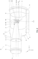
- FIG. 2 schematically shows the physics package 12 of the optical lattice clock according to the embodiment.
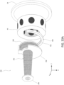
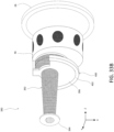
- FIG. 3 schematically shows an example of the appearance of the physics package 12.
- FIG. 4 is a partially perspective view of the internal structure of the physics package 12 shown in FIG. 3 .
- FIGS. 2 to 4 (and the diagrams thereafter) show an XYZ orthogonal rectilinear coordinate system having an origin in a target space (clock transition space 52) where atoms to be described later can reside during clock transition spectroscopy.
- the physics package 12 includes a vacuum chamber 20, an atomic oven 40, a coil 44 for a Zeeman slower, an optical resonator 46, a coil 48 for a MOT (Magneto-Optical Trap) device, a cryostat reservoir 54, a thermal link member 56, a refrigerator 58, a vacuum pump main body 60, and a vacuum pump cartridge 62.
- a vacuum chamber 20 an atomic oven 40, a coil 44 for a Zeeman slower, an optical resonator 46, a coil 48 for a MOT (Magneto-Optical Trap) device, a cryostat reservoir 54, a thermal link member 56, a refrigerator 58, a vacuum pump main body 60, and a vacuum pump cartridge 62.
- MOT Magnetic-Optical Trap
- the vacuum chamber 20 is a case that maintains the main portion of the physics package 12 to be vacuum, and is formed to have a substantially cylindrical shape.
- the vacuum chamber 20 includes a main body 22 formed to have a large substantially cylindrical shape, and a protruding portion 30 formed to have a small substantially cylindrical shape that protrudes from the main body 22.
- the main body 22 is a portion that internally stores the optical resonator 46 to be described later and the like.
- the main body 22 includes a cylindrical wall 24 that serves as a side surface of the cylinder, and a front circular wall 26 and a rear circular wall 28 which serve as circular surfaces of the cylinder.
- the front circular wall 26 is a wall provided with the protrusion 30.
- the rear circular wall 28 is a wall opposite to the protruding portion 30, and has a shape with a diameter larger than that of the cylindrical wall 24.
- the protruding portion 30 includes a cylindrical wall 32 serving as a side surface of the cylinder, and a front circular wall 34.
- the front circular wall 34 is a circular surface remote from the main body 22.
- a portion of the protruding portion 30 adjacent to the main body 22 has an almost open shape, is connected to the main body 22, and has no wall portion.
- the vacuum chamber 20 is arranged so that the central axis (this axis is called a Z-axis) of the cylinder of the main body 22 is substantially horizontal.
- the central axis (this axis serves as a beam axis) of the cylinder of the protruding portion 30 extends in parallel with the Z-axis above the Z-axis in the vertically upward direction.
- the vacuum chamber 20 is assumed to be formed to be, for example, about 35 cm or less in the Z-axis direction, and about 20 cm or less in the X-axis direction and the Y-axis direction. Further miniaturization is also assumed so as to be about 30 cm or less, about 25 cm or less, or about 20 cm or less in the Z-axis direction. Also in the X-axis direction and the Y direction, it is assumed to be about 15 cm or less, or about 10 cm or less.
- the distance between the beam axis and the Z-axis is configured to be, for example, about 10 to 20 mm.
- the vacuum chamber 20 is made sufficiently robust from metal, such as SUS (stainless steel), so as to withstand difference in air pressure when the inside becomes vacuum.
- the vacuum chamber 20 is formed so that the rear circular wall 28 and the front circular wall 34 are detachable. These walls are detached at maintenance check.
- the atomic oven 40 is a device provided around the distal end of the protruding portion 30.
- the atomic oven 40 causes a heater to heat an arranged solid metal, emits, through a pore, atoms ejected from the metal owing to thermal agitation, and forms an atom beam 42.
- the beam axis on which the atom beam 42 passed is configured in parallel with the Z-axis, and is configured to intersect with the X-axis at a position slightly apart from the origin.
- the intersecting position corresponds to a capture space 50 that is a minute space where atoms to be described later are captured.
- the atomic oven 40 is basically provided in the vacuum chamber 20. However, its heat radiator extends to the outside of the vacuum chamber 20 for cooling.
- the atomic oven 40 heats the metal to about 750K, for example.
- the metal for example, any of strontium, mercury, cadmium, ytterbium, and the like may be selected. However, the metal is not limited thereto
- the coil 44 for the Zeeman slower is arranged on the downstream side of the beam axis of the atomic oven 40, from the protruding portion 30 to the main body 22 of the vacuum chamber 20.
- the coil 44 for the Zeeman slower is a device made by integrally including a Zeeman slower that decelerates the atoms of the atom beam 42, and a MOT device that captures the decelerated atoms. Both the Zeeman slower and the MOT device are devices based on an atomic laser cooling technology.
- the coil 44 for the Zeeman slower shown in FIG. 2 is provided with a Zeeman coil used for the Zeeman slower, and one of the pair of MOT coils used for the MOT device, as a series of coils.
- the large portion from the upstream to the downstream corresponds to the Zeeman coil that generates a magnetic field contributing to the Zeeman slowing method, and the furthest downstream side corresponds to the MOT coil that generates a gradient magnetic field contributing to the MOT method.
- the Zeeman coil is of a decreasing type that has a greater number of turns on the upstream side and a smaller number of turns on the downstream side.
- the coil 44 for the Zeeman slower is axisymmetrically arranged around the beam axis so that the atom beam 42 passes through the inside of the Zeeman coil and the MOT coil.
- a magnetic field caused to have a spatial gradient is formed, and emission of a Zeeman slower optical beam 82 decelerates atoms.
- the optical resonator 46 is a cylindrical component arranged around the Z-axis, and enables formation of an optical lattice therein. Multiple optical components are installed in the optical resonator 46. One pair of optical mirrors on the X-axis, and another pair of optical mirrors in parallel therewith are provided, and optical lattice light is multiply reflected between the four mirrors, thus generating a bow-tie-shaped optical lattice resonator. The atom population captured in the capture space 50 is confined in the optical lattice.
- the relative frequencies of two optical lattice light beams (clockwise and counterclockwise) caused to enter the optical resonator 46 are shifted, and this resonator forms a moving optical lattice that causes the standing wave of the optical lattice to move.
- the moving optical lattice moves the atom population to the clock transition space 52.
- an optical lattice including the moving optical lattice is configured to be formed on the X-axis.
- the optical resonator 46 can be called an optical lattice formation portion forming an optical lattice.
- the optical resonator 46 is also a device based on the atomic laser cooling technology.
- the coil 48 for the MOT device generates a gradient magnetic field for the capture space 50.
- the MOT device emits MOT light beams respectively along three, or X, Y, and Z, axes in a space where the gradient magnetic field is formed. Accordingly, the MOT device captures atoms in the capture space 50.
- the capture space 50 is configured on the X-axis.
- the coil 44 for the Zeeman slower shown in FIG. 2 is provided with a Zeeman coil used for the Zeeman slower, and one of the pair of MOT coils used for the MOT device, as a series of coils.
- the gradient magnetic field that contributes to the MOT method is generated integrally by the coil 48 for the MOT device and a portion of the coil 44 for the Zeeman slower.
- the cryostat reservoir 54 is formed so as to enclose the clock transition space 52, and keep the inner space at a low temperature. Accordingly, in an inner space, blackbody radiation decreases.
- the thermal link member 56 also serving as a support structure is attached to the cryostat reservoir 54. The thermal link member 56 transfers heat from the cryostat reservoir 54 to the refrigerator 58.
- the refrigerator 58 keeps the cryostat reservoir 54 at a low temperature via the thermal link member 56.
- the refrigerator 58 includes a Peltier element, and cools the cryostat reservoir 54 to about 190K, for example.
- the vacuum pump main body 60 and the vacuum pump cartridge 62 are devices for vacuumizing the vacuum chamber 20.
- the vacuum pump main body 60 is provided outside of the vacuum chamber 20.
- the vacuum pump cartridge 62 is provided in the vacuum chamber 20.
- the vacuum pump cartridge 62 is heated by a heater provided at the vacuum pump main body 60 and is activated. Accordingly, the vacuum pump cartridge 62 is activated, and absorbs atoms, thus achieving a vacuum.
- the vacuum pump cartridge 62 is installed in the main body 22 so as to be in parallel with the coil 44 for the Zeeman slower.
- the coil 44 for the Zeeman slower is arranged along the beam axis decentered in the X-axis direction from the central axis of the cylinder of the main body 22. Accordingly, there is a relatively large space on the opposite side away from the direction in which the coil 44 for the Zeeman slower is eccentrically arranged.
- the vacuum pump cartridge 62 is installed in this space.
- the physics package 12 includes, as components of the optical system: vacuum-resistant optical windows 64 and 66 for optical lattice light; a vacuum-resistant optical window 68 for MOT light; vacuum-resistant optical windows 70 and 72 for Zeeman slower light and MOT light; and optical mirrors 74 and 76.
- the vacuum-resistant optical windows 64 and 66 for optical lattice are vacuum-resistant optical windows provided on opposite cylindrical walls 24 of the main body 22 of the vacuum chamber 20 so as to face each other.
- the vacuum-resistant optical window 64 and 66 for optical lattice light are provided so as to enable entry and emission therethrough of optical lattice light.
- the vacuum-resistant optical window 68 for MOT light is provided so as to enable entry and emission therethrough of MOT light beams on two axes, among MOT light beams on the three axes used for the MOT device.
- the vacuum-resistant optical windows 70 and 72 for Zeeman slower light and MOT light are provided so as to enable entry and emission therethrough of Zeeman slower light and MOT light on one axis.
- the optical mirrors 74 and 76 are provided so as to change the directions of the Zeeman slower light and the MOT light on the one axis.
- the physics package includes, as components for cooling: a cooler 90 for an atomic oven; a cooler 92 for a Zeeman slower; and a cooler 94 for a MOT device.
- the cooler 90 for the atomic oven is a water-cooling device that cools the atomic oven 40.
- the cooler 90 for the atomic oven is provided outside of the vacuum chamber 20, and cools a radiator of the atomic oven 40, the radiator extending outside of the vacuum chamber 20.
- the cooler 90 for the atomic oven includes a water-cooling tube that is a tube made of metal and is for cooling, and causes flow of cooling water, which is a liquid coolant, in the tube, thus cooling the vacuum chamber 20.
- the cooler 92 for the Zeeman slower is a device that is provided on the wall portion of the vacuum chamber 20, and cools the coil 44 for the Zeeman slower.
- the cooler 92 for the Zeeman slower includes a tube made of a metal, and flows cooling water in the tube, thus removing Joule heat generated at the coil of the coil 44 for the Zeeman slower.
- the cooler 94 for the MOT device is a heat radiator provided on the circular wall portion of the vacuum chamber 20. At the coil 48 for the MOT device, Joule heat is generated at the coil, although the amount of Joule heat is smaller (e.g., about 1/10) than that of the cooler 92 for the Zeeman slower. Accordingly, the metal of the cooler 94 for the MOT device extends to the outside of the vacuum chamber 20 from the coil 48 for the MOT device, and radiates heat to the atmosphere.
- the physics package 12 further includes, as components for correcting a magnetic field: a triaxial magnetic field correction coil 96; a vacuum-resistant electric connector 98; an individual magnetic field compensation coil 102 for a refrigerator; and an individual magnetic field compensation coil 104 for the atomic oven.
- the triaxial magnetic field correction coil 96 is a coil for uniformly nullifying the magnetic field in the clock transition space 52.
- the triaxial magnetic field correction coil 96 is formed to have a three-dimensional shape so as to correct the magnetic field in the three, or X, Y, and Z, axes.
- the triaxial magnetic field correction coil 96 is formed to have a substantially cylindrical shape as a whole.
- Each of coils constituting the triaxial magnetic field correction coil 96 is formed to have a point-symmetric shape centered in the clock transition space 52 in each axis direction.
- the vacuum-resistant electric connector 98 is a connector for supplying electric power to the inside of the vacuum chamber 20, and is provided on the circular wall portion of the vacuum chamber 20. From the vacuum-resistant electric connector 98, power is supplied to the coil 44 for the Zeeman slower, the coil 48 for the MOT device, and the triaxial magnetic field correction coil 96.
- the individual magnetic field compensation coil 102 for the refrigerator is a coil for compensating the stray magnetic field from the refrigerator 58 that cools the cryostat reservoir 54.
- the Peltier element included in the refrigerator 58 is a large current device where relatively large current flows, and generates a large magnetic field.
- the magnetic field is shielded by a high permeability material. However, complete shielding is not achieved, and part of the magnetic field leaks. Accordingly, the individual magnetic field compensation coil 102 for the refrigerator is configured so as to compensate the stray magnetic field in the clock transition space 52.
- the individual magnetic field compensation coil 104 for the atomic oven is a coil for compensating the stray magnetic field from the heater of the atomic oven 40.
- the heater of the atomic oven 40 is also a large current device, and the stray magnetic field cannot be ignored in some cases even with shielding by a high permeability material.
- a heater circuit is made of noninductive winding, an induced component remains in actuality, in wiring via a wiring terminal and an insulating layer.
- the individual magnetic field compensation coil 104 for the atomic oven is configured so as to compensate the stray magnetic field in the clock transition space 52.
- the vacuum pump cartridge 62 included in the vacuum chamber 20 absorbs atoms, thus vacuumizing the inside of the vacuum chamber 20. Accordingly, for example, the inside of the vacuum chamber 20 is in a vacuum state of about 10 -8 Pa, which eliminates the effect of air components, such as nitrogen and oxygen.
- a preprocess is preliminarily executed. For example, for a non-evaporable getter pump (NEG pump) and an ion pump, rough pumping must be performed from the atmosphere to a certain degree of vacuum before their operation.
- NAG pump non-evaporable getter pump
- ion pump rough pumping must be performed from the atmosphere to a certain degree of vacuum before their operation.
- a rough pumping port is provided for the vacuum chamber, and rough pumping is sufficiently performed through the port using a turbomolecular pump, for example.
- a turbomolecular pump for example, in a case of using a NEG pump as the vacuum pump main body 60, a step of activation of heating to a high temperature in a vacuum must be preliminarily executed.
- the metal is heated by the heater to a high temperature, and atomic vapor is generated.
- the atomic vapor emitted from the metal in this process sequentially passes through the pore, is converged, translates, and forms an atom beam 42.
- the atomic oven 40 is installed so as to form the atom beam 42 on the beam axis in parallel with the Z-axis.
- an atomic oven main body is heated by a heater.
- the atomic oven main body and a joint that supports this main body are thermally insulated via a thermal insulator.
- a joint connected to the physics package is cooled by the cooler 90 for the atomic oven, thus preventing the physics package 12 from being affected by a high temperature, or reducing the adverse effect of the high temperature.
- the coil 44 for the Zeeman slower is installed so as to be axisymmetrical with respect to the beam axis.
- the inside of the coil 44 for the Zeeman slower is irradiated with the Zeeman slower optical beam 82 and the MOT optical beam 84 on one axis.
- the Zeeman slower optical beam 82 enters from the vacuum-resistant optical window 70 for Zeeman slower light and MOT light, and is reflected by the optical mirror 74 installed downstream of the beam away from the coil 48 for the MOT. Accordingly, the Zeeman slower optical beam 82 is overlaid on the atom beam 42, and travels upstream of the beam axis in parallel to the beam axis.
- the atoms in the atom beam 42 absorb the Zeeman slower light, are given momentum in the deceleration direction, and are decelerated.
- the Zeeman slower light is reflected upstream of the coil 44 for the Zeeman slower by the optical mirror 76 disposed aside of the beam axis, and is emitted through the vacuum-resistant optical window 72 for Zeeman slower light and MOT light.
- the coil 44 for the Zeeman slower generates Joule heat.
- cooling is performed by the cooler 92 for the Zeeman slower. Accordingly, the temperature is prevented from being high.
- the sufficiently decelerated atom beam 42 reaches the MOT device that includes the MOT coil on the furthest downstream side of the coil 44 for the Zeeman slower, and the coil 48 for the MOT device.
- the MOT device a magnetic field having a linear spatial gradient is formed centered in the capture space 50.
- the MOT device is irradiated with MOT light in the three-axis directions, in the positive and negative sides.
- the MOT optical beam 84 in the Z-axis direction is emitted in the negative direction of the Z-axis, and is then reflected outside of the vacuum-resistant optical window 72 for Zeeman slower light and MOT light, thus being emitted also in the positive direction of the Z-axis.
- MOT optical beams 86a and 86b on the remaining two axes are emitted into the MOT device through the vacuum-resistant optical window 68 for MOT light and by an optical mirror, not shown. As shown in FIG. 4 , these two axes are in two directions perpendicular to the Z-axis and inclined respectively from the X-axis and the Y-axis by 45 degrees; emission is performed in these two directions.
- the configuration allowing the two MOT optical beams 86a and 86b to be perpendicular to the Z-axis can narrow the distance between the coil 44 for the Zeeman slower and the coil 48 for the MOT device, thus contributing to miniaturization of the vacuum chamber 20.
- the directions of emission of the MOT optical beams are configured to be inclined respectively from the Z-axis and the Y-axis by 45 degrees
- the distance in the beam axis must be large so as to prevent the MOT optical beams from interfering with the Zeeman slower and the cryostat reservoir.
- the device size is larger than in the case where the two axes of the MOT light beams are perpendicular to the Z-axis.
- the atom beam receives a restoring force centered in the capture space 50 by the magnetic field gradient and is decelerated. Accordingly, the atom population is captured in the capture space 50. Note that the position of the capture space 50 can be finely adjusted by adjusting the offset values for the magnetic field to be generated by the triaxial magnetic field correction coil 96.
- the Joule heat generated at the coil 48 for the MOT device is discharged outside of the vacuum chamber 20 by the cooler 94 for the MOT device.
- An optical lattice light beam 80 enters in the X-axis through the vacuum-resistant optical window 64 for optical lattice light toward the vacuum-resistant optical window 66 for optical lattice light.
- the optical resonator 46 including two optical mirrors is installed, and causes reflection. Accordingly, on the X-axis there is formed an optical lattice potential with a series of standing waves in the X-axis direction in the optical resonator 46. The atom population is captured by the optical lattice potential.
- the optical lattice can be moved along the X-axis by slightly changing the wavelength.
- movement means through the moving optical lattice the atom population is moved to the clock transition space 52.
- the clock transition space 52 is apart from the beam axis of the atom beam 42. Accordingly, the effects of blackbody radiation emitted from the atomic oven 40 at a high temperature can be removed.
- the clock transition space 52 is enclosed by the cryostat reservoir 54, and is shielded from blackbody radiation emitted from ambient materials at ordinary temperatures.
- blackbody radiation is proportional to the fourth power of the absolute temperature of a material. Accordingly, reduction in temperature by the cryostat reservoir 54 exerts a large advantageous effect of removing the impact of the blackbody radiation.
- atoms are irradiated with laser light whose optical frequency is under control, highly accurate spectroscopy of clock transitions (i.e., resonance transitions of atoms serving as the reference of the clock) is performed, and the frequency that is specific to the atom and invariant is measured.
- highly accurate spectroscopy of clock transitions i.e., resonance transitions of atoms serving as the reference of the clock
- the frequency that is specific to the atom and invariant is measured.
- an accurate atomic clock is achieved. Improvement of the accuracy of the atomic clock requires removal of perturbation around the atoms, and accurate reading of the frequency. It is particularly important to remove the frequency shift caused by the Doppler effect due to the thermal agitation of the atoms.
- the atom movement is frozen by confining the atoms in a space sufficiently smaller than the wavelength of the clock laser by the optical lattice created by interference of the laser light. Meanwhile, in the optical lattice, the frequencies of atoms are shifted by laser light that forms the optical lattice.
- a specific wavelength or frequency called "magic wavelength” or “magic frequency” is selected, which removes the effects of the optical lattice to the resonant frequency.
- the clock transitions are also affected by a magnetic field. Atoms in the magnetic field cause Zeeman splitting dependent on the intensity of the magnetic field. Accordingly, the clock transitions cannot be accurately measured.
- the magnetic field is corrected so as to equalize and nullify the magnetic field.
- a stray magnetic field caused by the Peltier element of the refrigerator 58 is dynamically compensated by the individual magnetic field compensation coil 102 for the refrigerator that generates a compensation magnetic field dependent on the intensity of the stray magnetic field.
- the individual magnetic field compensation coil 104 for the atomic oven.
- the magnetic field of the clock transition space 52 is further corrected by the triaxial magnetic field correction coil 96.
- the triaxial magnetic field correction coil 96 includes multiple coils in each axis, and can remove not only uniform components of the magnetic field but also spatially varying components.
- the atom population is urged to subjected to clock transition by laser light.
- Light emitted as a result of the clock transition is received by the optical system device, subjected to a spectroscopic process and the like by the control device, and the frequency is obtained.
- embodiments of the physics package 12 are described in detail.
- the triaxial magnetic field correction coil 96 in the physics package 12 is described.
- the triaxial magnetic field correction coil 96 is assumed to be formed to have a predetermined shape by winding a covered conductor wire that includes a conducive wire made of copper or the like and is subjected to an insulating process with a polyimide resin.
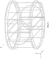
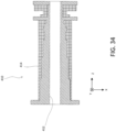
- FIG. 5 is a perspective view showing all the coils of the triaxial magnetic field correction coil 96.
- FIGS. 6 to 11 are perspective views showing individual coils that constitute the triaxial magnetic field correction coil.
- the triaxial magnetic field correction coil 96 is attached around an inner wall of the main body 22 of the vacuum chamber 20. Accordingly, the triaxial magnetic field correction coil 96 is formed to have a substantially cylindrical shape centered in the clock transition space 52.
- the triaxial magnetic field correction coil 96 includes a first coil group and a second coil group in each of the directions of the X-axis, Y-axis, and Z-axis.
- FIG. 6 shows a first coil group 120 in the X-axis direction (a direction in which an optical lattice in one axis is formed, and the moving optical lattice moves).
- the first coil group 120 includes two coils 122 and 124 installed apart from each other by a distance c in the X-axis direction centered in the clock transition space 52.
- Each of the coils 122 and 124 is each formed to have a rectangle with the length of the side in the Y-axis direction being a, and the length of the side in the Z-axis direction being b.
- Each of the coils 122 and 124 is formed to have a point-symmetric shape with respect to the clock transition space 52.
- the first coil group 120 causes the coils 122 and 124 to have a square-shaped Helmholtz-type coil so as to substantially uniformly generate the magnetic field at a central portion in the X-axis direction.
- the coils 122 and 124 serve as a Helmholtz-type coil pair that form a magnetic field having high uniformity in the X-axis direction.
- currents having different magnitudes and directions are allowed to flow through the coils 122 and 124.
- the coils 122 and 124 can sufficiently improve the uniformly of the magnetic field even in a case of a ⁇ b.
- the deviation of the magnetic field distribution in the Y-axis direction tends to be smaller than that of the magnetic field distribution in the Z-axis direction.
- the deviation of the magnetic field distribution in the Z-axis direction tends to be smaller than that of the magnetic field distribution in the Y-axis direction.
- c is optimized by what is called a rectangular Helmholtz-type coil.
- the first coil group 120 may be configured as a rectangular Helmholtz-type coil.
- the first coil group 120 is used to adjust the value of the magnetic field component in the X-axis direction, and its first order spatial derivative term in the X-axis direction.
- a magnetic field of a linear sum of 1) and 2) is formed. Accordingly, the first coil group 120 can correct the constant term component of the magnetic field component Bx in the X-axis direction in the clock transition space 52, and its first order spatial derivative term in the X-axis direction.
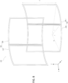
- FIG. 7 shows a second coil group 130 in the X-axis direction.
- the second coil group 130 includes two coils 132 and 134 installed apart from each other in the X-axis direction centered in the clock transition space 52.
- Each of the coils 132 and 134 is formed to have shapes obtained by deforming rectangular coils to have a curvature so that the coils can be laid on the same cylindrical surface having a radius e and are configured so that the central angle is f, and the height in the Z-axis direction is g.
- the cylindrical surface is formed to have a radius substantially identical to that of a cylindrical surface onto which the first coil group 120 in FIG. 6 is fixed. Accordingly, the relationship e 2 ⁇ (a/2) 2 + (c/2) 2 holds.
- the coils 132 and 134 are formed to have a point-symmetric shape with respect to the clock transition space 52.
- the second coil group 130 is a non-Helmholtz-type coil that has a shape different from that of the Helmholtz coil.
- the coils 132 and 134 of the second coil group are electrically connected to each other. Currents with the same magnitude flow through the coils in the same direction. That is, currents flow in the direction of an arrow 136 or currents flow in the direction of an arrow 138 through both the coils 132 and 134. Since the second coil group 130 is a non-Helmholtz-type coil, a non-uniform component is also generated in addition to a uniform component according to a Helmholtz coil in the clock transition space 52 at the center. Note that the magnitudes and the directions of currents are the same.
- the non-uniform component is mainly a second order spatial derivative term component. That is, the second coil group 130 can correct the constant term component of the magnetic field component Bx in the X-axis direction in the clock transition space 52, and its second order spatial derivative term in the X-axis direction.
- the magnetic field component Bx in the X-axis direction in the triaxial magnetic field correction coil 96 is basically controlled by the first coil group 120 and the second coil group 130 in the X-axis direction. Accordingly, these are collectively called an X-axis magnetic field correction coil.
- To perform correction first, the value of the second order spatial derivative term in the X-axis direction is nullified by the second coil group 130. Subsequently, adjustment of nullifying the value of the first order spatial derivative term in the X-axis direction and nullifying the constant term in the X-axis direction by the first coil group 120 is performed.
- FIG. 8 shows a first coil group 140 in the Y-axis direction.
- the first coil group 140 is formed by deforming rectangular coils so as to have a curvature, and is laid on a cylindrical surface having a radius h centered in the clock transition space 52.
- the first coil group includes a composite coil 142 made up of a coil 143 and a coil 144, and a composite coil 145 made up of a coil 146 and a coil 147, the composite coils being installed apart from each other in the Y-axis direction.
- the coils 143, 144, 146, and 147 are configured so that the central angle is i and the height in the Z-axis direction is j.
- the coils 143 and 144 are formed so that their edges can overlap with or be adjacent to each other.
- the coils 146 and 147 are formed so that their edges can overlap with or be adjacent to each other.
- the composite coil 142 and the composite coil 145 are point-symmetrically formed centered in the clock transition space 52.
- the coil 143 and the coil 146, and the coil 144 and the coil 147 are point-symmetrically formed centered in the clock transition space 52.
- the first coil group 140 can equalize the component of the magnetic field in the Y-axis direction around the center by adjusting the direction and magnitude of the current allowed to flow.
- the current is slightly changed from the current when the Helmholtz coil is formed. Specifically, only currents through the coil 143 and the coil 147 are slightly increased in the same direction. In this case, the component of the magnetic field in the Y-axis direction has the value of the first order spatial derivative term in the X-axis direction. Note that in a strict sense, the magnetic field formed by the coil 143 and the coil 147 has a component in the X-axis direction. When the first coil group 140 is adjusted, the X-axis magnetic field correction coil also must be adjusted.
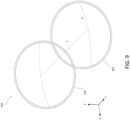
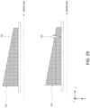
- FIG. 9 shows a second coil group 150 in the Y-axis direction.
- the second coil group 150 shown in FIG. 9 is made up of a pair of coils 152 and 154 that face each other in the Y-axis direction.
- Each of the coils 152 and 154 is a non-Helmholtz-type coil formed to have a shape obtained by causing a circular coil having a radius k to have a curvature, and laying the coil on the plane of a cylinder with a radius l centered in the clock transition space 52.
- the non-Helmholtz-type coil also forms the second order spatial derivative term component of the magnetic field. Accordingly, the second coil group 150 is used to control the X-axis-direction second order spatial derivative term of the magnetic field component By in the Y-axis direction.
- the first coil group 140 in the Y-axis direction shown in FIG. 8 and the second coil group 150 in the Y-axis direction shown in FIG. 9 basically form a Y-axis magnetic field correction coil that corrects the magnetic field component By in the Y-axis direction.
- the Y-axis magnetic field correction coil can correct the constant term of the magnetic field component By in the Y-axis direction, the first order spatial derivative term in the X-axis direction, and the second order spatial derivative term in the X-axis direction.
- FIG. 10 shows a first coil group 160 in the Z-axis direction.
- the first coil group 160 includes circular composite coils 162 and 165 that have a radius m and are arranged to face each other and separated by a distance n.
- the composite coils 162 and 165 are point-symmetric with respect to the center.
- the composite coil 162 includes semicircular coils 163 and 164 whose chords overlap with or are adjacent to each other.
- the semicircular coil 163 is arranged on the positive side of the X-axis, and the semicircular coil 164 is arranged on the negative side of the X-axis.
- the composite coil 165 is formed by combining a semicircular coil 166 on the positive side of the X-axis and a semicircular coil 167 on the negative side of the X-axis.
- the composite coils 162 and 165 are configured to have sizes and the like so as to serve as a Helmholtz-type coil.
- the composite coils 162 and 165 are configured so that when currents having the same magnitude flow in the same direction, the uniformity of the magnetic field in the Z direction around the center is substantially equivalent to that of a Helmholtz coil. Note that the directions and magnitudes of the currents through the coils 163 and 164, which constitute the composite coil 162, can be freely changed. Accordingly, similar to the first coil group 140 in the Y direction shown in FIG. 8 , the first coil group 160 can correct the constant term and the X-axis-direction first order spatial derivative term of the magnetic field component Bz in the Z direction.
- FIG. 11 shows a second coil group 170 in the Z-axis direction.
- the second coil group 170 includes circular coils 172 and 174 that have a radius p and are apart by a distance q in the Z-axis direction facing each other.
- the second coil group 170 is a non-Helmholtz-type coil.
- the non-Helmholtz-type coil has a non-uniform component. Accordingly, the X-axis-direction second order spatial derivative term of the magnetic field component Bz in the Z-axis direction can be corrected.
- the first coil group 160 in the Z-axis direction shown in FIG. 10 and the second coil group 170 in the Z-axis direction shown in FIG. 11 basically form a Z-axis magnetic field correction coil that corrects the magnetic field component Bz in the Z-axis direction.
- the Z-axis magnetic field correction coil can correct the constant term of the magnetic field component Bz in the Z-axis direction, the first order spatial derivative term in the X-axis direction, and the second order spatial derivative term in the X-axis direction.
- the triaxial magnetic field correction coil 96 shown in FIG. 5 is formed by controlling the X-axis magnetic field correction coil, the Y-axis magnetic field correction coil, and the Z-axis magnetic field correction coil in a combined manner.
- the triaxial magnetic field correction coil 96 can correct the constant term, the X-axis-direction first order spatial derivative term, and the X-axis-direction second order spatial derivative term of the magnetic field component Bx in the X-axis direction.
- the constant term, the X-axis-direction first order spatial derivative term, and the X-axis-direction second order spatial derivative term of the magnetic field component By in the Y-axis direction can be corrected.
- the constant term, the X-axis-direction first order spatial derivative term, and the X-axis-direction second order spatial derivative term of the magnetic field component Bz in the Z-axis direction can be corrected.
- the triaxial magnetic field correction coil 96 performs correction of uniformly nullifying the value of the magnetic field of the clock transition space 52.
- the clock transition space 52 is configured to have dimensions such as 10 mm in the X-axis direction (the direction of the lattice), and about 1 to 2 mm in the Y-axis and Z-axis directions, for example.
- the error of the magnetic field is controlled so as to be within 3 ⁇ G, within 1 ⁇ G, or within 0.3 ⁇ G.
- the Helmholtz-type coils and the non-Helmholtz-type coils included in the triaxial magnetic field correction coil 96 are configured to have accuracies so as to be capable of forming the magnetic field.
- the triaxial magnetic field correction coil 96 is formed to have a point-symmetric shape centered in the clock transition space 52, and can accurately correct the magnetic field in the clock transition space 52.
- the capture space 50 is present around the center of the triaxial magnetic field correction coil. Accordingly, use for correcting the magnetic field of the capture space 50 due to the MOT device is also available. That is, the current is controlled to correct the magnetic field of the capture space 50 in a time period in which the MOT device is activated and captures atoms from the atom beam 42. After the capture is finished, power transmission to the coil 44 for the Zeeman slower and the coil 48 for the MOT device is stopped, and the magnetic field of the clock transition space 52 is corrected.
- the position of the capture space 50 is adjusted with high accuracy, and the atom population can be efficiently confined in the optical lattice.
- FIG. 12 shows a cylindrical holder 180 to which the triaxial magnetic field correction coil 96 is attached.
- the holder 180 includes circular ring-shaped frames 182 and 184, and eight linear frames 186 that connect the frames 182 and 184.
- the triaxial magnetic field correction coil 96 is attached to the inner wall and the outer wall of the holder 180.
- the holder 180 is then fixed to the rear circular wall 28 of the main body 22 of the vacuum chamber 20.
- the holder 180 is made of a low-permeability material such a resin, aluminum, or the like in order not to affect the magnetic field created by the triaxial magnetic field correction coil 96.
- the holder 180 is installed in the main body 22 so as to be coaxial with the central axis of the cylinder of the main body 22.
- the holder 180 is formed to have a size close to the inner diameter of the main body 22. Accordingly, the triaxial magnetic field correction coil 96 and the holder 180 hardly occupy the space in the main body 22.
- the coils 122 and 124 which are the first coil group 120 in the X-axis direction, are attached linearly across the inside of the main body 22.
- the holder 180 is formed to have a sparse structure using the frames.
- the sparse structure is a structure having many interspaces on each surface.
- the sparse structure of the holder 180 reduces the weight, and facilitates prevention of interference with laser light that enters and is emitted from the vacuum chamber 20.
- the triaxial magnetic field correction coil 96 may be, for example, attached only to the inner wall of the holder 180 or attached only to the outer wall of the holder 180, instead of being attached to the inner wall and the outer wall of the holder 180. In this case, for example, fixation can be easily achieved using a circular ring-shaped fastener that presses the triaxial magnetic field correction coil 96 against the outer wall, or a circular ring-shaped fastener that presses the coil against the inner wall.
- the triaxial magnetic field correction coil 96 can be fixed to the inner wall of the main body 22 without using the holder 180.
- the triaxial magnetic field correction coil 96 described above is formed by winding a covered conductor wire one or multiple times.
- the triaxial magnetic field correction coil 96 can be partially or entirely made of a flexible printed board.
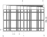
- FIG. 13 shows a flexible printed board developed on a plane.
- a correction coil 190 is formed on the flexible printed board.
- the correction coil 190 includes current paths 192 that are made of a printed electric conductor, such as copper, and contribute to forming the magnetic field, and an insulator 194 made of a sheet-shaped flexible resin or the like, and can be flexibly bent.
- Each current path 192 is connected to a wiring path 196 provided intensively on one end.
- the wiring path 196 is made of a print made of an electric conductor.
- the wiring path arranges a pair where currents reciprocate, so as to be adjacent to each other, and cancel magnetic fields to be formed therearound.
- the wiring path 196 is connected to a terminal connector 198.
- FIG. 14 shows the cylindrically bent correction coil 190 along the main body 22 of the vacuum chamber 20.
- the correction coil 190 includes a boundary portion 199 where the two edges are connected to or arranged adjacent to each other. Note that in FIG. 14 , the wiring path 196 and the terminal connector 198 are omitted.
- the triaxial magnetic field correction coil configured with the flexible printed board is assumed to be attached to the inner wall of the cylindrical main body 22 or to the cylindrical holder 180.
- the triaxial magnetic field correction coil 96 includes a current path disengaged from the cylindrical surface, in addition to the current path arranged on the cylindrical surface. Specifically, a side having a length a of the first coil group 120 in the X-axis direction shown in FIG. 6 , and a linear portion of the first coil group 160 in the Z-axis direction shown in FIG. 10 are disengaged from the cylindrical surface.
- current paths arranged on the cylindrical surface are formed on a flexible printed board.
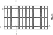
- FIGS. 15 and 16 show an example of forming a coil at the circular portion of the first coil group 160 in the Z-axis direction shown in FIG. 10 using a flexible printed board.
- counterclockwise currents flow through current paths 202 indicated by black lines, but no current flows to current paths 200 indicated by gray lines.
- this is equivalent to a case where currents flow through virtual current paths 203 shown in FIG. 16 .
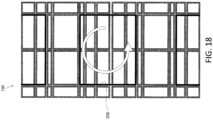
- FIGS. 17 and 18 show an example of forming the outermost coil of the first coil group 140 in the Y-axis direction shown in FIG. 8 using a flexible printed board.
- counterclockwise currents flow through current paths 206 indicated by black lines, but no current flows to current paths 204 indicated by gray lines.
- this is equivalent to a case where currents flow through virtual current paths 208 shown in FIG. 18 .
- various current paths can be formed, including a current path going back around the outer periphery of the cylindrical surface about the central axis of the cylinder, and a current path going back on the cylindrical surface not about the central axis of the cylinder.
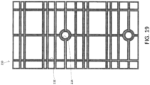
- a pattern made up of rectangular current paths can be printed on the flexible printed board. Similar to a correction coil 210 shown in FIG. 19 , a composite pattern that includes rectangular current paths 211 and circular current paths 214 can be printed. In the physics package 12, a laser light path, a vacuum-resistant optical window, and the like are provided around the wall surface of the vacuum chamber 20. Accordingly, it is effective to provide the circular current paths 214 and prevent interference.
- the coils as shown in FIGS. 16 and 18 may be formed. Multiple flexible printed boards may be used in an overlaid manner. Thus, a portion or the entirety of the triaxial magnetic field correction coil may be formed using multiple boards.
- a minute amount of gas may be emitted from a resin of the insulator 194. Accordingly, for the insulator 194, a material with a small amount of gas emission, such as polyimide resin, is selected. It is conceivable that a production step performs a baking process at an appropriate temperature, in addition to a deaeration process, a defoaming process, a cleaning process, and the like.
- the triaxial magnetic field correction coil formed of a flexible printed board may be installed in the vacuum chamber 20 in various forms.
- the triaxial magnetic field correction coil is installed around the inner wall of the main body 22 in a state of being cylindrically bent, and the triaxial magnetic field correction coil is fixed to the main body 22 with a fastener that presses the coil against the main body 22.
- installation may be done by attaching to the holder 180.
- a holder that has a dense structure with not many pores may be adopted so as to support the flexible printed board on a plane.
- a current path disengaged from the cylindrical surface may be separately formed using a covered conductor wire.
- a current path disengaged from the cylindrical surface may also be created by adopting the flexible printed board.
- the triaxial magnetic field correction coil using the flexible printed board has advantages that facilitate attachment to the vacuum chamber 20, and improve production reproducibility and production yield.
- the coil shape of the triaxial magnetic field correction coil may be configured in various other forms.
- a large-sized circular coil is arranged at the middle of two circular coils, thus enabling formation of a Maxwell type triaxial magnetic field correction coil.
- the components of the constant term, the first order spatial derivative term, and the second order spatial derivative term of the magnetic field can be corrected.
- small circular coils that have a predetermined size and are provided at predetermined intervals are arranged outside of a pair of large circular coils that have a predetermined size and are provided at predetermined intervals, thus enabling formation of a tetra type axial magnetic field correction coil.
- the components of the constant term, the first order spatial derivative term, the second order spatial derivative term, and the third order spatial derivative term of the triaxial magnetic field correction coil can be corrected.
- the axial magnetic field correction coil described above has a spherical shape or a slightly distorted spherical shape as a whole. Accordingly, in particular, attachment to the inner wall of the substantially spherical vacuum chamber or therearound enables effective utilization of the inner space of the vacuum chamber.
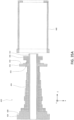
- FIG. 20 is a diagram corresponding to FIG. 4 , and schematically shows the appearance and the inside of a physics package 218. Components identical or corresponding to those in FIG. 4 are assigned the same or corresponding symbols.
- a vacuum chamber 220 of the physics package 218 is made up of a substantially spherical main body 222, and a protruding portion 30.
- a triaxial magnetic field correction coil 224 made up of circular coils is provided centered in the clock transition space 52.
- FIG. 20 only shows a pair of Helmholtz-type coil in each axis direction. In actuality, one or more non-Helmholtz-type coils are assumed to be further provided on each axis.
- the outer edge of the triaxial magnetic field correction coil 224 can be configured to form a substantially spherical surface. Accordingly, by installing the triaxial magnetic field correction coil 224 in the substantially spherical main body 222 around the inner wall, interference with the other components installed in the inner space of the main body 222 can be prevented, and design flexibility is improved.
- the triaxial magnetic field correction coil may be constructed using square coils. Similar to the circular coils, there may be adopted a Helmholtz type triaxial magnetic field correction coil including each pair of square coils, a Maxwell type triaxial magnetic field correction coil including three square coils, a tetra type triaxial magnetic field correction coil including two pair of square coils, and the like. These triaxial magnetic field correction coils have a cubic shape or a slightly distorted cubic shape as a whole. Accordingly, attachment to the inner wall or the inner wall surface of the substantially-cubic-shaped or substantially-cuboid-shaped vacuum chamber enables effective utilization of the inner space of the vacuum chamber.
- the triaxial magnetic field correction coil may be attached to a position closer to the clock transition space 52 than to the inner wall of the main body 22.
- FIG. 21 schematically shows the inside of the optical resonator 46 shown in FIG. 1 and therearound. Note that in FIG. 21 , instead of the triaxial magnetic field correction coil 96 in FIG. 1 , a cubic-shaped triaxial magnetic field correction coil 230 is provided at a space between the coil 44 for the Zeeman slower and the coil 48 for the MOT device. The cubic-shaped triaxial magnetic field correction coil 230 is arranged centered in the clock transition space 52 in the cryostat reservoir 54. The cubic-shaped triaxial magnetic field correction coil 230 is formed of two pairs of coil groups made up of square coils in each of the three-axis directions.
- the cubic-shaped triaxial magnetic field correction coil 230 can compensate the magnetic field component up to the third order spatial derivative term.
- the magnetic field component up to the second order spatial derivative term can be simply compensated.
- the triaxial magnetic field correction coil 230 is significantly small sized, and is close to the clock transition space 52. Accordingly, the magnetic field formed in the clock transition space 52 varies in a relatively small spatial scale.
- the triaxial magnetic field correction coil 230 through the Helmholtz-type coil, can compensate the constant term and the first order spatial derivative term over a relatively large range. At least the magnetic field component of the second order spatial derivative term can be compensated through the non-Helmholtz-type coil. Consequently, the magnetic field of the clock transition space 52 is uniformly nullified with sufficiently high accuracy. Since the triaxial magnetic field correction coil 230 is at a position close to the clock transition space 52, the current caused to flow to form the magnetic field can be significantly small, thereby achieving excellent power saving capability.
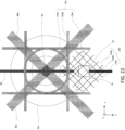
- FIG. 22 is a side view from a direction A in FIG. 21 .
- the capture space 50 is irradiated with two MOT optical beams 86a and 86b that are perpendicular to the Z-axis and inclined by 45 degrees from the X-axis and the Y-axis.
- a MOT optical beam 84 is emitted.
- a bias coil 234 is arranged centered in the capture space 50.
- the bias coil 234 includes: a pair of Helmholtz type circular coils 234a that face each other along the beam axis; a pair of Helmholtz type square coils 234b that face each other along the X-axis; and a pair of Helmholtz type square coils 234c that face each other along the Y-axis.
- the bias coil 234 corrects the gradient magnetic field to a desired distribution by adjusting the constant term component or the first order spatial derivative term component through the coils in each axis.
- the triaxial magnetic field correction coil 230 is provided centered in the clock transition space 52 around the cryostat reservoir 54.
- the triaxial magnetic field correction coil 230 includes: a coil group 230b whose plane has a normal in parallel with the Z-axis; and two coil groups 230a and 230c whose planes have a normal perpendicular to the Z-axis and are inclined from the X-axis and the Y-axis by 45 degrees. That is, the triaxial magnetic field correction coil 230 is arranged in a state where a cubic shape along the X-axis, the Y-axis, and the Z-axis is rotated about the Z-axis by 45 degrees.
- the triaxial magnetic field correction coil 230 is supported by flanges 44a and 48a that are support members supporting the MOT device. Accordingly, the triaxial magnetic field correction coil 230 must be arranged close to the capture space 50 at the center of the MOT device. Meanwhile, the triaxial magnetic field correction coil 230 must be arranged so as to prevent interference with the MOT optical beams 86a and 86b passing through the capture space 50. Accordingly, the triaxial magnetic field correction coil 230 is arranged to have a shape along the Z-axis and the MOT optical beams 86a and 86b.
- the triaxial magnetic field correction coil 230 includes a Helmholtz-type coil and a non-Helmholtz-type coil in each axis direction. Equalization of the magnetic field in a large space that includes correction of the higher order spatial derivative terms can be achieved. Accordingly, also in the X-axis direction that is the direction of the optical lattice light beam 80, the magnetic field can be corrected with high accuracy.
- the triaxial magnetic field correction coil 230 does not enclose the capture space 50. Accordingly, the magnetic field in the capture space 50 cannot be corrected. Accordingly, as described above, the bias coil 234 that corrects the gradient magnetic field is provided in the capture space 50.
- FIGS. 20 and 21 exemplify the triaxial magnetic field correction coil 230 made of square coils.
- coils having other shapes, such as circular coils instead of the square coils may be adopted.
- the cylindrical-shaped triaxial magnetic field correction coil 96 shown in FIGS. 5 to 11 may be adopted.
- the triaxial magnetic field correction coil may be provided to each of a position close to the clock transition space 52 and a position around the inner wall of the main body 22.
- a Helmholtz-type coil may be provided around the inner wall of the main body 22, and a non-Helmholtz-type coil may be provided at a position close to the clock transition space 52.
- Adjustment of the magnetic field by the triaxial magnetic field correction coil is described.
- the magnetic field distribution is periodically observed around the clock transition space 52, and when a non-uniform magnetic field distribution is identified, the currents through the triaxial magnetic field correction coil 96 are operated so as to cancel the magnetic field distribution.
- the magnetic field distribution is observed by moving the atom population confined in the optical lattice by means of the moving optical lattice.
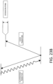
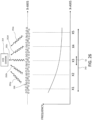
- FIGS. 23A and 23B schematically show a process of adjusting the triaxial magnetic field correction coil.
- FIG. 23A shows a state of moving an atom population 240 confined in the moving optical lattice along the X-axis.
- FIG. 23B shows the relationship between the fluorescence transition and the clock transition.
- the atom population 240 is confined in the lattices sequential in the X-axis direction with a certain spatial extent.
- representative positions on the X-coordinate where the atom population 240 moves are represented as a position X1, a position X2, a position X3, a position X4, and a position X5.
- These are positions set in the correction space 242 set for correcting the magnetic field.
- the correction space 242 is set over a wide range including the clock transition space 52 that performs actual measurement.
- the embodiment adopts the one-dimensional lattice with the optical lattice extending in the X-axis direction, and the atom population 240 ranges in a manner extending in the X-axis direction.
- the correction space 242 is set over an extent in the X-axis direction. Note that in a case where the optical lattice is two-dimensionally formed, it is desirable to set a correction space obtained by extending the clock transition space 52 two-dimensionally. In a case where the optical lattice is three-dimensionally formed, it is desirable to set a correction space obtained by extending the clock transition space 52 three-dimensionally.
- the atom population 240 is irradiated with laser light for exciting clock transition, and the clock transition is excited.
- the frequency of the laser light is swept, and the frequency of clock transition is measured at each position.
- the electron shelving method is used to observe the excitation rate of clock transition.
- the electron shelving method excites clock transition and subsequently moves the atoms to a fluorescent observation space 243.
- FIG. 23B by emitting light of fluorescence transition, the atoms emit fluorescent light 244 dependent on the excitation rate.
- the fluorescent light is observed by an optical receiver 246.
- the clock transition is subjected to Zeeman splitting depending on the magnitude of the magnetic field at each position. Accordingly, the magnetic field distribution at each position is obtained from information on the Zeeman splitting.
- the thus obtained frequency distribution is shown in the lower part of FIG. 23A .
- the magnetic field can be measured even at a location where no fluorescent light can be observed (in a cryo head, etc.).
- a non-destructive measurement method using a measurement of phase shifts of atoms can be applied to the measurement of the excitation rate of clock transition.
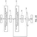
- FIGS. 24 and 25 are flowcharts illustrating procedures for correcting the magnetic field by the triaxial magnetic field correction coil.
- calibration is performed.
- currents in all the coils constituting the triaxial magnetic field correction coil are stopped (set to 0 A), and the distribution of the magnetic field in the three-axis directions is measured (S10).
- the magnetic field measurement for example, the magnetic fields in the three-axis directions are measured using a magnetic sensor, such as a small-sized coil or a Hall element.
- the measured magnetic field represents the value of the background in a state where the triaxial magnetic field correction coil is not used.
- the calibration may measure the magnetic field of the correction space 242.
- the correction space 242 is in the cryostat reservoir 54. Accordingly, it is not always easy to install a magnetic sensor. Accordingly, the magnetic field may be measured adjacent to the correction space 242, and the magnetic field may be estimated based on a result of an electromagnetic field simulation combined therewith. The magnetic field may be measured in the atmosphere instead of a vacuum. Accordingly, the basic magnetic field distribution formed by each coil of the triaxial magnetic field correction coil with a current of 1 A may be grasped. In principle, it is sufficient to perform the calibration once at a stage of creating the physics package 12.
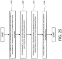
- the magnetic field is corrected.
- the atom population 240 is moved by the moving optical lattice, and the frequency of clock transition is measured at each position in the correction space 242 (S20).
- the effect of Zeeman splitting is estimated, thus obtaining the magnetic field distribution in the correction space 242 (S22).
- the magnetic field distribution is obtained as the absolute value of the magnetic field.
- the current corresponding to the magnetic field to be corrected by each coil is determined using an optimization method, such as the least squares method (S24). That is, there is obtained the superimposition coefficient such that the magnetic field formed in the correction space 242 is uniformly zero when the basic magnetic fields formed by the respective coils are superimposed.
- S24 the least squares method
- the optimal superimposition for the constant term and the first order spatial derivative term generated by the Helmholtz-type coil is obtained by the least squares method or the like. Accordingly, calculation is simplified, and the calculation accuracy is improved.
- the obtained superimposition coefficients indicate the direction and magnitude of the current caused to flow to each coil.
- the obtained currents are caused to flow to the triaxial magnetic field correction coil, thereby enabling correction of the magnetic fields of the three axes (S26).
- the correction indicated in FIG. 25 is not necessarily frequently performed under a normal condition where the magnetic field varied little.
- the magnetic field of the triaxial magnetic field correction coil is corrected for the range of the correction space 242
- fine-scale disturbances such as a slight fluctuation of the magnetic field, the error of magnetic field measurement, and the error of the basic magnetic field of each coil, affect the case where only a narrow space, such as the clock transition space 52, is adopted as a target.
- the correction space 242 is adopted as a target and corrected, and a result of improving the accuracy is obtained.
- FIG. 26 schematically shows an example of measuring the magnetic field distribution in the correction space 242 at one time.
- the atom population 250 is confined in the optical lattice over the entire area of the correction space 242.
- the fluorescent light beams 252a, 252b, 252c, 252d, and 252e of the atom population 250 are received at one time with spatial position information being left, by a CCD camera 254, and the frequencies are obtained. Accordingly, the magnetic field distribution of the correction space 242 is immediately obtained.
- the individual magnetic field compensation coil 102 for the refrigerator is provided, and compensates the magnetic field in the clock transition space 52.
- the individual magnetic field compensation coil 104 for the atomic oven is provided, and compensates the magnetic field in the clock transition space 52.
- the individual magnetic field compensation coil 102 for the refrigerator is exemplified and described in detail.
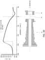
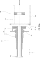
- FIG. 27 schematically shows example configurations of the cryostat reservoir 54, the thermal link member 56, the refrigerator 58, and the individual magnetic field compensation coil 102 for the refrigerator.
- the cryostat reservoir 54 is a hollow component that encloses the clock transition space 52. Although not shown, an opening for allowing optical lattice light to pass therethrough internally is provided along the X-axis on the wall portion of the cryostat reservoir 54.
- the cryostat reservoir 54 is made of oxygen-free copper having high thermal conductivity or the like.
- the thermal link member 56 is attached to the cryostat reservoir 54.
- the thermal link member 56 is a member that serves as a support structure that supports the cryostat reservoir 54 and also as a path that removes heat from the cryostat reservoir 54.
- the thermal link member 56 is also made of oxygen-free copper having high thermal conductivity or the like.
- the refrigerator 58 includes a Peltier element 58a, a radiator plate 58b, a heat-insulating member 58c, and permalloy magnetic field shields 58d and 58e.
- the Peltier element 58a is connected to the thermal link member 56, and removes heat from the thermal link member 56 with current flowing therethrough.
- the radiator plate 58b is a member made of oxygen-free copper having high thermal conductivity or the like.
- the radiator plate 58b is provided on the outer wall of the vacuum chamber 20, and radiates heat transmitted from the Peltier element 58a to the outside of the vacuum chamber 20.
- the heat-insulating member 58c secures the heat insulation between the permalloy magnetic field shield 58d and the thermal link member 56.
- the heat-insulating member 58c is made of a member, such as of silica having low thermal conductivity, and is spherically formed in order to reduce the number of contacts between the permalloy magnetic field shield 58d and the thermal link member 56.
- the permalloy magnetic field shield 58e is a magnetic field shield, and is made of permalloy, which has high thermal conductivity and high permeability.
- the permalloy magnetic field shield 58e is provided between the Peltier element 58a and the radiator plate 58b, and transmits heat from the Peltier element 58a to the radiator plate 58b.
- a temperature sensor 260 that includes a thermocouple, a thermistor, or the like is provided in the cryostat reservoir 54, and inputs a measured temperature T1 into the control device 262.
- a temperature sensor 264 is provided at or around the radiator plate 58b, and inputs a measured temperature T2 into the control device 262.
- the control device 262 controls current so as to keep the temperature T1 of the cryostat reservoir 54 at a certain low temperature (e.g., 190K).
- the control is performed, for example, according to PID (Proportional Integral Differential) control in consideration also of the temperature T2 on the radiator plate 58b side.
- the determined current is caused to flow to the Peltier element 58a through a current path 266.
- the Peltier element 58a is a thermoelectric element that moves heat depending on the flowing current. By causing the current to flow, the Peltier element 58a removes heat from the thermal link member 56 (and from the low cryostat reservoir 54 connected to the thermal link member 56) on the low temperature side, and releases the heat to the permalloy magnetic field shield 58e (and to the radiator plate 58b connected to the permalloy magnetic field shield 58e) on the high temperature side.
- the Peltier element 58a Through the Peltier element 58a, a large current of, for example, about several amperes is caused to flow. Accordingly, a large magnetic field is generated.
- the greater portion of the Peltier element 58a is covered with the permalloy magnetic field shield 58d and the permalloy magnetic field shield 58e, which are of the high permeability material. Accordingly, most of the generated magnetic field flows in these members, and is not leaked to the outside.
- a magnetic field cannot be provided between the thermal link member 56 and the Peltier element 58a. Accordingly, the stray magnetic field 270 occurs.
- the stray magnetic field 270 disturbs the magnetic field in the clock transition space 52 in the cryostat reservoir 54.
- the individual magnetic field compensation coil 102 for the refrigerator is provided around the thermal link member 56 serving as an opening portion where the magnetic field cannot be shielded.
- the individual magnetic field compensation coil 102 for the refrigerator generates a compensation magnetic field 272 when a current flows.
- the current is caused to flow to the individual magnetic field compensation coil 102 for the refrigerator by a current path 268 branched off the current path 266. That is, the Peltier element 58a and the individual magnetic field compensation coil 102 for the refrigerator have a relationship of being connected to the same current path in parallel.
- the electrical resistance of the Peltier element 58a and the electrical resistance of the individual magnetic field compensation coil 102 for the refrigerator may be assumed to have constant values in a temperature environment where measurement is performed, although the values vary slightly. Consequently, the current that flows from the control device 262 to the current path 266 is distributed to the Peltier element 58a and the individual magnetic field compensation coil 102 for the refrigerator at constant ratios.
- the current flowing through the Peltier element 58a increases, the current flowing through the individual magnetic field compensation coil 102 for the refrigerator increases proportionally. Accordingly, when the stray magnetic field 270 from the Peltier element 58a increases, the compensation magnetic field 272 generated by the individual magnetic field compensation coil 102 for the refrigerator increases in the same manner.
- the individual magnetic field compensation coil 102 for the refrigerator is formed so as to compensate the stray magnetic field 270 in the clock transition space 52 in the cryostat reservoir 54 (so as to generate a magnetic field having the same magnitude in the opposite direction) when a current having a certain magnitude flows through the current path 266. Accordingly, even when the current varies, the magnetic field can be compensated. Note that the currents flow also through the current paths 266 and 268. However, the reciprocating currents flow close to each other through the current paths 266 and 268. Accordingly, the generated magnetic field is small, which causes no problem.
- the arrangement of the current paths 266 and 268 may be regarded as compensation current control means for dynamically changing the current flowing through the individual magnetic field compensation coil 102 for the refrigerator depending on the stray magnetic field 270.
- the compensation current control means may be constructed in another manner. For example, there can be exemplified a mode where the control device 262 causes the current required by the computation to flow through the individual magnetic field compensation coil 102 for the refrigerator.
- the individual magnetic field compensation coil 102 for the refrigerator is formed of one coil wound around the thermal link member 56.
- the individual magnetic field compensation coil 102 for the refrigerator is provided adjacent to the wall of the vacuum chamber 20, which can prevent the configuration around the cryostat reservoir 54 from being complicated.
- the installation location of the individual magnetic field compensation coil 102 for the refrigerator is not specifically limited. For example, it may be installed adjacent to the cryostat reservoir 54. In a case where the individual magnetic field compensation coil 102 for the refrigerator is installed adjacent to the cryostat reservoir 54, the individual magnetic field compensation coil 102 for the refrigerator can be reduced in size, and the power consumption can be reduced.
- the individual magnetic field compensation coil 102 for the refrigerator is not necessarily formed of one coil, and may be formed of multiple coils. In a case where the distribution of the stray magnetic field in the clock transition space 52 is complicated, there is a possibility that use of multiple coils can achieve compensation in relatively simple manner.
- the current device, the individual magnetic field compensation coil, and the compensation current control means constitute the magnetic field compensation module.
- the magnetic field compensation module can achieve accurate magnetic field compensation. Accordingly, this module is applicable to various devices including the optical lattice clock 10.
- FIG. 28 shows sectional views of the coil 44 for the Zeeman slower, and the coil 48 for the MOT device.
- a coil 282 is wound around an elongated cylindrical-shaped bobbin 280 arranged coaxially with the beam axis.
- a hollow portion of the bobbin around the center is a space through which the atom beam 42 travels along the beam axis.
- the greater portion of the coil 282 constitutes a decreasing type Zeeman coil portion 284 where the number of turns substantially decreases slightly from the upstream side to the downstream side of the beam axis.
- the furthest downstream side of the coil 282 in the beam axis and therearound forms the MOT coil portion 286 having a large number of turns.
- the covered conductor wires of the Zeeman coil portion 284 and the MOT coil portion 286 are continuously connected to each other, the magnetic field formed by the Zeeman coil portion 284 extends adjacent to the MOT coil portion 286, and the magnetic field formed by the MOT coil portion 286 extends downstream of the Zeeman coil portion 284. Consequently, it should be noted that the boundary between the Zeeman coil portion 284 and the MOT coil portion 286 cannot be clearly defined.
- a disk-shaped upstream flange 288 On the beam-axis upstream side of the bobbin 280 there is provided a disk-shaped upstream flange 288 having a radius larger than the maximum diameter portion of the Zeeman coil portion 284.
- the upstream flange 288 is attached to the cylindrical wall 32 of the protruding portion 30 of the vacuum chamber 20.
- a mirror supporter is attached to a front portion of the upstream flange 288.
- the optical mirror 76 is attached to the distal end of the mirror supporter.
- downstream flange 290 and 292 On the beam-axis downstream side of the bobbin 280, there are provided two circular ring-shaped downstream flanges 290 and 292 formed to have a diameter substantially identical to that of the MOT coil portion 286.
- the downstream flange 290 is formed to have a circular ring shape that is relatively thick along the beam axis direction, and is provided around the boundary between the Zeeman coil portion 284 and the MOT coil portion 286.
- the downstream flange 292 is formed to have a circular ring shape that is relatively thin along the beam axis direction, and is provided downstream of the MOT coil portion 286.
- the upper parts of the downstream flanges 290 and 292 are attached to the upper support member 312, and the lower parts of the flanges are attached to the lower support member 314.
- the upper support member 312 and the lower support member 314 are attached to the rear circular wall 28 of the main body 22 of the vacuum chamber 20.
- the coil 48 for the MOT device is arranged downstream of the coil 44 for the Zeeman slower away by a predetermined distance.
- a MOT coil 302 is wound around a short cylindrical-shaped bobbin 300 provided coaxially with the beam axis.
- On the beam-axis upstream side of the bobbin 300 there is provided a thin circular ring-shaped flange 304 having a diameter substantially identical to that of the MOT coil 302.
- a relatively thick circular ring-shaped flange 306 having a diameter substantially identical to that of the MOT coil 302 is provided.
- the upper parts of the flanges 304 and 306 are attached and fixed to the upper support member 312.
- the bobbin 280, the upstream flange 288, and the downstream flanges 290 and 292 are made of copper or the like, which has high thermal conductivity and low permeability.
- the bobbin 280, the upstream flange 288, and the downstream flanges 290 and 292 are combined with each other by welding to have high strength and to be in close contact.
- the coil 44 for the Zeeman slower more coil is wound around on the beam-axis upstream side.
- the upstream side has a greater weight than the downstream side.
- the coil 44 for the Zeeman slower heat is generated by the current flowing through the coil 282.
- the vacuum chamber 20 is in a vacuum. Unlike the atmosphere, thermal conduction via a gas does not occur. Accordingly, in the coil 44 for the Zeeman slower, a slight cooling effect due to blackbody radiation occurs. However, the heat of the coil 282 must be removed mainly by thermal conduction via a solid.
- the bobbin 280 is in contact with the coil 282, and heat is effectively transferred from the coil 282.
- the upstream flange 288 and the downstream flanges 290 and 292 have a large area in contact with the coil 282, and remove heat from the coil 282. As shown in FIG.
- the upstream flange 288 is connected to the cooler 92 for the Zeeman slower at the cylindrical wall 32 of the protruding portion 30.
- cooling water is circulated in a water-cooling tube made of copper or the like, thereby cooling the upstream flange 288.
- the bobbin 300 and the flanges 304 and 306 of the coil 48 for the MOT device also have high thermal conductivity, and are made of copper or the like having low permeability.
- the bobbin 300, and the flanges 304 and 306 are combined with each other by welding to have high strength and to be in close contact.
- the MOT coil 302 of the coil 48 for the MOT device is smaller in size and lighter in weight than the coil 282 of the coil 44 for the Zeeman slower.
- the entire coil 48 for the MOT device also has a light weight. Accordingly, the coil 48 for the MOT device is stably attached to the rear circular wall 28 via the upper support member 312 to which the flanges 304 and 306 are fixed.
- the current caused to flow is smaller and the amount of heat generation is smaller in the MOT coil 302 of the coil 48 for the MOT device than in the coil 282 of the coil 44 for the Zeeman slower.
- the peripheries of the MOT coil 302 in three directions of the coil 48 for the MOT device are enclosed by the bobbin 300 and the flanges 304 and 306. Accordingly, the heat generated by the MOT coil 302 is transmitted to the cooler 94 for the MOT device via the upper support member 312. It is assumed that a cooling scheme is adopted for the cooler 94 for the MOT device. However, in a case where the heat quantity to be removed is small, an air cooling scheme may be adopted.
- the number of turns of the coil 282 decreases roughly monotonically.
- irregularities are formed in the beam axis direction.
- One reason for providing the irregularities is to obtain a desired magnetic field intensity at a specific position on the beam axis.
- the magnetic field must be zero.
- Another reason may be to adopt a configuration of causing no magnetic field at positions where no magnetic field is required, in view of power saving. It is sufficient that the coil 44 for the Zeeman slower generates a magnetic field needed to decelerate atoms or confine atoms.
- a reason for providing irregularities may be a request for mechanical support or thermal radiation. The weight of the coil increases with the number of turns.
- the coil 282 of the coil 44 for the Zeeman slower is formed to have a relatively convex shape where the number of turns is large at a portion in contact with the upstream flange 288, and to have a relatively concave shape where the number of turns is relatively small on the downstream side. Accordingly, the barycenter of the coil 44 for the Zeeman slower moves toward the upstream flange 288, and fixation by the upstream flange 288 is more stable.
- the contact area between the coil 282 and the upstream flange 288 is large, and thermal conduction is effectively achieved from the coil 282 to the upstream flange 288.
- FIG. 29 shows sectional views of upper parts of two Zeeman coils 320 and 330.
- the number of turns monotonically decreases in the beam axis direction including the portion 322.
- the number of turns is locally small at the portion 322 called a void.
- the number of turns ais locally large before and after the portion 332 in the beam axis direction. Accordingly, the distribution of the magnetic field created by the entire Zeeman coil 330 is substantially equal to the distribution of the magnetic field created by the Zeeman coil 320.
- the way of forming the coil shape at and around the void can be theoretically obtained.
- the magnetic field distribution generated by a unit component is in accordance with the Biot-Savart law. Conversion from the magnetic field distribution to the current distribution can be dealt with as the deconvolution method, or the inverse problem in a general perspective.
- the method of obtaining a solution of a minimum current path through the inverse problem is described, for example, in Mansfield P, Grannell PK. "NMR Diffraction in Solids.” J Phys C: Solid State Phys 6:L422-L427, 1973. However, it is obvious that there are multiple roots only if there is no restriction to the minimum current.
- the solution of the minimum current path satisfying a desired magnetic field distribution is the Zeeman coil 320, the Zeeman coil 330 with increased current density around the void can also form a desired magnetic field distribution.
- the downstream flange 290 is provided at the middle of the coil 282. This means that the downstream flange 290 is provided at the large void. Before and after the downstream flange 290 in the beam direction, the numbers of turns is configured to be larger than in a case without the downstream flange 290, thus removing or reducing the adverse effects of the downstream flange 290.
- FIG. 30 shows the magnetic field distribution at the coil 44 for the Zeeman slower and the coil 48 for the MOT device.
- the x axis represents the position on the beam axis. The origin corresponds to the capture space 50.
- the y axis represents the magnitude of the magnetic field on the beam axis.
- the coil 44 for the Zeeman slower and coil 48 for the MOT device are formed symmetrically with respect to the beam axis. Accordingly, the magnetic field on the beam axis only has a component on the beam axis direction.
- a position where the coil 282 of the coil 44 for the Zeeman slower is arranged, and a position where the MOT coil 302 of the coil 48 for the MOT device is arranged are indicated. Points on the graph indicate calculated values of the magnetic field.
- Narrow lines indicate the value of the magnetic field that is ideal for decelerating atoms toward the capture space 50 by the Zeeman slower.
- the magnetic field becomes the maximum slightly downstream of the end of the coil 282 on the upstream side.
- the value of the magnetic field abruptly decreases.
- the value gradually approaches zero.
- the ideal magnetic field has a distribution where the magnetic field outside of the coil 282 becomes zero, and no magnetic field leaks to the outside.
- generation of the magnetic field due to the current has a spatial extension.
- the magnetic field outside of the coil 282 cannot be zero.
- the magnetic field decreases monotonically.
- the number of turns of the coil has slight irregularities as described above.
- the monotonically decreasing magnetic field for Zeeman slower is created.
- the magnetic field having the gradient substantially coincides with the ideal magnetic field distribution for Zeeman slower, and indicates steady deceleration of atoms toward the capture space 50.
- the magnetic field abruptly decreases before the end of the downstream side of the coil 282.
- the MOT coil portion 286 therearound has a large number of turns. No coil is present on the further downstream side. Accordingly, the value of the magnetic field rapidly decreases.
- the magnetic field decreases with a substantially constant slope, and becomes zero in the capture space 50. Furthermore, the magnetic field decreases with the same slope, and becomes the minimum value (the negative value becomes strongest) around the MOT coil 302 of the coil 48 for the MOT device. This is because the MOT coil 302 causes the current to flow in the direction opposite to the coil 282. A portion ranging from a portion around the MOT coil portion 286 of the coil 282 to a portion around the MOT coil 302 approximately forms a Helmholtz-type coil. Accordingly, by causing the current to flow through the MOT coil 302 in the opposite direction, the magnetic field having a constant slope can be formed.
- the magnetic field having a constant slope is formed also in a direction perpendicular to the beam axis.
- the gradient magnetic field formed by the MOT device is irradiated with MOT optical beams in the respective three axes. Accordingly, the atoms can be captured in the capture space 50 at the origin.
- the magnetic field gradually approaches zero.
- the coil 44 for the Zeeman slower and the coil 48 for the MOT device are installed in the combined manner, and the length in the beam axis direction is allowed to be reduced in comparison with a case where the Zeeman slower and the MOT device are separately provided.
- the entire coil length can be also reduced, which can facilitate power saving and reduction in amount of heat generation.
- the triaxial magnetic field correction coil 96 or a bias coil for correcting the gradient magnetic field is adjusted, thus allowing generation of the compensation magnetic field that cancels the background magnetic field around the capture space 50.
- FIG. 31A is a sectional view showing a state before the coil 340 for the Zeeman slower is attached to the inside of the vacuum chamber 20.
- FIG. 31B is a sectional view showing a state after the attachment.
- a coil 342 of the coil 340 for the Zeeman slower shown in FIG. 31A serves as the Zeeman coil portion 344 whose greater portion of the beam-axis upstream side has a function of a Zeeman coil.
- the furthest downstream side of the coil 342 serves as a MOT coil portion 346 where the function of the Zeeman coil and the function of the MOT coil reside in a combined manner.
- the number of turns monotonically increases from the end of the upstream side to the downstream side. Around the end on the downstream side, irregularities are repeated, and subsequently the number of turns becomes the maximum on the most downstream side.
- a portion with the maximum number of turns and therearound is called the MOT coil portion 346. As described above, in view of functionality, the portion also plays a role of a Zeeman coil.
- the coil 340 for the Zeeman slower internally includes a bobbin.
- a flange 350 is provided at the end on the upstream side.
- a flange 352 is provided at the middle of the coil 342 around the end on the downstream side.
- a flange 354 is provided on the end on the downstream side. The flanges 350, 352, and 354 are welded to the bobbin.
- a mirror supporter is attached to the furthest upstream flange 350.
- the optical mirror 76 is fixed to the mirror supporter.
- the downstream flanges 352 and 354 are linked to each other at portions other than the bobbin, and improve strength.
- the flange 352 is a large disk that is thin and has a large radius.
- the flange 352 is attached to the circular ring supporter 370 made to have a ring shape.
- the ring of the circular ring supporter 370 internally includes a water-cooling tube 372 through which cooling water flows, and cools the coil 342 through the flange 352.
- Right and left beams 374 are attached to an upper portion of the circular ring supporter 370.
- Right and left beams 376 also serving as water-cooling tubes are attached to a lower portion of the circular ring supporter 370.
- the beams 374 and 376 are attached to the rear circular wall 28 of the main body 22 of the vacuum chamber 20, and support the entire portion including the coil 340 for the Zeeman slower.
- the beams 374 and 376 serve as exhaust heat paths for transmitting heat of the coil 342 to the rear circular wall 28. Note that cooling water flowing through the beams 376 is allowed to be circulated to the radiator plate 58b of the refrigerator 58.
- This configuration assumes that a coil 380 for the MOT device is attached to the rear circular wall 28 by a separately provided support member.
- the coil 340 for the Zeeman slower is assumed to be positioned with the coil 380 for the MOT device by a positioning mechanism.
- FIG. 32 is a diagram corresponding to FIG. 30 , and shows the magnetic distribution in a case where the increasing type coil 340 for the Zeeman slower and the coil 380 for the MOT device are adopted.
- Magnetism gradually increases from the downstream side of the coil 342 of the coil 340 for the Zeeman slower, and becomes the maximum value before the MOT coil portion 346.
- the increase in magnetism coincides well with a target curve required to achieve the Zeeman slower.
- the magnetism On the downstream side of the position with the maximum value, the magnetism rapidly decreases. Before and after the capture space 50 serving as the origin, the magnetism decreases from positive to negative at a substantially constant slope, and becomes zero in the capture space 50.
- the magnetic field becomes the minimum around the coil 380 for the MOT device, and subsequently gradually approaches zero.
- the slope of the magnetic field becomes abrupt in comparison with the case of the decreasing type in FIG. 30 . This is because the number of turns of the MOT coil 346 at the coil 342 is large, and the number of turns of the facing coil 380 for the MOT device is also large. By making the slope of the magnetic field steep, atoms can be captured with a short distance in the beam axis direction.
- the increasing type coil 340 for the Zeeman slower shown in FIG. 32 can have a shorter length than the decreasing type coil 44 for the Zeeman slower in FIG. 30 . This is because the increasing type can efficiently decelerate atoms. The increasing type can suppress the magnetic field required to decelerate the atoms and achieve power saving in comparison with the decreasing type.
- the side of the capture space 50 is heavier. Accordingly, it is difficult to support the coil in the vacuum chamber 20.
- the increasing type has a larger number of turns on the capture space 50 side. Accordingly, problems are caused in that the amount of heat generation is large around the center of the vacuum chamber 20 and it is difficult to cool.
- the coil 340 for the Zeeman slower is supported around the center of the vacuum chamber 20 by the circular ring supporter 370 having the cooling function. Accordingly, these problems are not caused.
- the mode of attaching the increasing type coil 340 for the Zeeman slower shown in FIGS. 31A and 31B is only an example. Another mode may be adopted. By reference to FIGS. 33A and 33B , a modified example is described.
- FIG. 33A is a perspective view showing a state before the coil 390 for the Zeeman slower is attached to the inside of the vacuum chamber 20.
- FIG. 33B is a perspective view showing a state after the attachment.
- a coil 392 of the coil 390 for the Zeeman slower is wound in a manner similar to that of the coil 340 for the Zeeman slower.
- the configuration including a bobbin and flanges 394, 396, and 398 is also almost the same.
- the shape of the flange 396 provided close to the lower end in the beam direction is a semicircular shape that is substantially about the lower half.
- a portion that supports the flange 396 serves as a substantially U-shaped semicircular ring supporter 400 obtained by halving a circular ring.
- the semicircular ring supporter 400 is provided with a water-cooling tube 402.
- the flange 396 has a semicircular shape.
- the cooling performance in a case where the cooling water circulation is equivalent decreases slightly.
- a space is present above the flange 396. Accordingly, in the vacuum chamber 20, access is facilitated from the optical resonator 46 toward the atomic oven 40. Presence of the space above the semicircular ring supporter 400 facilitates removal of the optical resonator 46. Furthermore, since the distance of the water-cooling tube in the vertical direction is reduced, the disturbance of the flow caused by convection in the water-cooling tube can be easily prevented. Note that the flange 396 shown in FIGS.
- 33A and 33B can be appropriately provided pores in its surface. In the case of providing the pores, the efficiency of thermal conduction decreases, but reduction in weight can be achieved. Likewise, the flange 352 shown in FIGS. 31A and 31B can be appropriately provided with pores in its surface.
- FIG. 34 is a sectional view of a coil 410 for an increasing type Zeeman slower according to another embodiment.
- the coil 410 for the Zeeman slower includes a bobbin 412 having a thickness varying in the beam direction.
- the cylindrical-shaped bobbin 412 has a constant inner diameter, but an outer diameter that gradually decreases stepwise from the upstream to the downstream in the beam direction.
- a coil 414 wound around the bobbin 412 has a greater number of turns on the downstream side in the beam axis direction. Accordingly, the outer diameter of the coil 414 is substantially constant in the beam axis direction.
- increase in the outer diameter of the bobbin 412 increases the contact area between the bobbin 412 and the coil 414. Accordingly, the thermal conduction efficiency from the coil 414 to the bobbin 412 improves.
- a covered conductor wire can be wound using the steps of the bobbin 412, thus facilitating installation of the coil 414.
- a rectangular flat wire having a rectangular section may be used for the covered conductor wire included in the coil 414, which can further improve the thermal conduction efficiency with the bobbin 412 and the like.
- the outer diameter of the coil 414 is constant, which facilitates bringing the cover into close contact with the coil 414, and removing heat through the cover.
- the example of installing the Zeeman slower in the vacuum chamber 20 has been described so far.
- the cooling mechanism of removing Joule heat caused by the coil is provided, which allows thermally stable installation of the Zeeman slower in the vacuum chamber 20.
- an example of sealing part or the entirety of the coil with the cover i.e., encapsulation
- FIGS. 35A and 35B are side sectional views showing a coil 420 for a Zeeman slower and a cover 440.
- FIG. 35A shows a state before the cover 440 is attached to the coil 420 for the Zeeman slower.
- FIG. 35B shows a state after the attachment.
- the coil 420 for the Zeeman slower is of the decreasing type where the number of turns of the coil gradually decreases in the beam axis direction.
- a bobbin 422 of the coil 420 for the Zeeman slower is provided with a flange 424 at the end of the upstream side of the beam axis, and with a flange 426 also at a middle position on the downstream side. Similar to the example described above, the bobbin 422 and the flanges 424 and 426 are made of copper or the like, which secures high thermal conductivity.
- the outer peripheries of the flanges 424 and 426 are provided respectively with sealing members 428 and 430 made of indium.
- the sealing members 428 and 430 are formed to have a ring shape, relatively thin sheet shape, or a ring-shaped thick shape. Indium has a characteristic stably enabling vacuum sealing even with large temperature variation.
- the flange 426 is provided with a hermetic connector 432 that is a vacuum-resistant connector.
- a coil 434 is wound around the bobbin 422 between the flange 424 and the flange 426.
- a coil 436 is wound on the downstream side of the flange 426.
- Each of the coils 434 and 436 is formed of a covered conductor wire including copper insulated with a resin. The coil 434 and the coil 436 are electrically connected via the hermetic connector 432.
- the cover 440 is formed to have a cylindrical shape.
- the cover 440 is made of copper, which is the same material as that of the bobbin 422, the flanges 424 and 426, and the coils 434 and 436, and prevents deformation due to thermal expansion.
- the cover 440 is installed for coverage from the flange 424 to the flange 426. That is, part of the inner periphery of upstream end of the cover 440 encloses part of the outer periphery of the flange 424, and is sealed with a sealing member 428. Part of the inner periphery of downstream end of the cover 440 encloses part of the outer periphery of the flange 426, and is sealed with a sealing member 430.
- the cover 440 is formed so as to have a positive tolerance from the length from the flange 424 to the flange 426, and can securely enclose both flanges.
- the atmospheric pressure can be freely set in the cover 440 only if the sealing members 428 and 430 can securely achieve shielding.
- air at the atmospheric pressure may be enclosed, or a roughly pumped vacuum may be used.
- the roughly pumped vacuum is a state of being rarefied using a turbopump or the like, and is set to about 1 to 0.1 Pa, for example.
- the inside of the cover 440 is the roughly pumped vacuum
- the pressure difference between the inside and the outside of the cover 440 is small in a state where the vacuum chamber 20 is in a vacuum. Accordingly, the sealing surfaces by the sealing members 428 and 430 can be strongly prevented from being separated from each other.
- An inert gas such as nitrogen or helium, may be enclosed in the cover 440.
- a gas having low reactivity with a resin used for the coil when the coil 434 is at a high temperature is selected as the inert gas.
- the pressure of the inert gas is not specifically limited, and may be one atmosphere, or a roughly pumped vacuum.
- the inside of the cover 440 may be filled with for example, a lightweight resin, such as urethane foam. In this case, the strength of the cover 440 can be improved.
- the coil 420 for the Zeeman slower becomes a high temperature due to Joule heat during energization.
- a coil 434 with a larger number of turns generates more Joule heat than a coil 436 with a smaller number of turns. Accordingly, the coil 434 tends to become a high temperature.
- a minute amount of gas (this gas is called outgas) contained in the resin of the covered conductor wire included in the coil 434 is discharged.
- the coil 420 for the Zeeman slower the coil 434 is sealed by the bobbin 422, the flanges 424 and 426, and the cover 440. Accordingly, no outgas leaks into the vacuum chamber 20. This prevents the outgas from causing an error of the clock transition. Consequently, the coil 420 for the Zeeman slower sealed by the cover 440 functions as a vacuum installation coil having high usability in a case of installation in a vacuum.
- the cover 440 also serves as a thermal conduction medium between the flange 424 and the flange 426. That is, thermal conduction between the flange 424 and the flange 426 occurs not only through the bobbin 422 but also through the cover 440. Accordingly, there is also an advantageous effect of cooling the coils 434 and 436.
- the cover 440 covers the outer peripheries of the flanges 424 and 426, but are not in contact with the coil 434.
- the cover 440 may be in contact with part or the entirety of the outer peripheral surface of the coil 434.
- heat from the coil 434 is directly transferred to the cover 440, which improves the heat radiation efficiency.
- the coil 414 has a constant outer diameter as with the coil 414 shown in FIG. 34 , it is easy to achieve close contact with the inner periphery of the cover 440. If it is difficult to form a shape bringing the cover 440 into contact with the outer peripheral surface of the coil 434, a thermal conductive member may be inserted between the cover 440 and the coil 434.
- the coil 434 is not covered with the cover 440. This is because the number of turns of the coil 434 is small, and the necessity of addressing outgas discharge is low.
- the coil 434 is a portion including the MOT coil included in the MOT device, and the optical resonator 46 and the like are arranged adjacent to this portion. Accordingly, increase in diameter due to coverage of the coil 434 with the cover is prevented. However, if interference with the surrounding devices and components can be avoided, the entire portion including the coil 434 may be covered with the cover and encapsulated.
- the decreasing type coil 420 for the Zeeman slower is exemplified.
- part or the entirety of what includes a portion having the large number of turns can be encapsulated.
- the cover 440 is in close contact with the flanges 424 and 426 using the indium sealing members 428 and 430, and the inside is made hermetic.
- sealing members made of a material other than indium may be adopted.
- the cover 440 may be detachably attached to the flanges 424 and 426 using fixation screws, for example.
- the cover 440 and the flanges 424 and 426 may be brought into close contact with each other by a semipermanent sealing method, such as welding or vacuum brazing, and the inside may be made hermetic.
- optical lattice clock examples include a clock and a clock that is an interferometer using atoms.
- this embodiment is also applicable to various types of quantum information processing devices for atoms (including ionized atoms).
- the quantum information processing devices are devices that perform measurement, sensing, and information processing using the quantum states of atoms and light, and may be, for example, a magnetic field meter, an electric field meter, a quantum computer, a quantum simulator, a quantum repeater, and the like besides an atomic clock and an atom interferometer.
- the physics package of the quantum information processing device can achieve miniaturization or transportability by using the technology of this embodiment, similar to the physics package of the optical lattice clock. It should be noted that in such devices the clock transition space is not a space for clock measurement but is sometimes dealt with simply as a space for causing clock transition spectroscopy.
- providing the triaxial magnetic field correction coil according to the embodiment can improve the accuracy of the device.
- providing the three axes according to the embodiment in the vacuum chamber miniaturization, transportability, or improvement in accuracy of the physical package can be achieved.
- the magnetic field compensation module the magnetic field distribution can be controlled with high accuracy. In the physics package using the vacuum chamber, installation of the vacuum installation coil is effective.
- optical lattice clock 10 optical lattice clock, 12 physics package, 14 optical system device, 16 control device, 18 PC, 20 vacuum chamber, 22 main body, 24 cylindrical wall, 26 front circular wall, 28 rear circular wall, 30 protruding portion, 32 cylindrical wall, 34 front circular wall, 38 leg, 40 atomic oven, 42 atom beam, 44 coil for Zeeman slower, 44a flange, 46 optical resonator, 48 coil for MOT device, 48a flange, 50 capture space, 52 clock transition space, 54 cryostat reservoir, 56 thermal link member, 58 refrigerator, 58a Peltier element, 58b radiator plate, 58c heat-insulating member, 58d, 58e permalloy magnetic field shield, 60 vacuum pump main body, 62 vacuum pump cartridge, 64, 66 vacuum-resistant optical window for optical lattice, 68 vacuum-resistant optical window for MOT light, 70, 72 vacuum-resistant optical window for MOT light, 74, 76 optical mirror, 80 optical lattice optical beam, 82 Zeeman slower
Landscapes
- Physics & Mathematics (AREA)
- Electromagnetism (AREA)
- General Physics & Mathematics (AREA)
- Engineering & Computer Science (AREA)
- Optics & Photonics (AREA)
- Nonlinear Science (AREA)
- Plasma & Fusion (AREA)
- Power Engineering (AREA)
- Chemical & Material Sciences (AREA)
- Analytical Chemistry (AREA)
- Stabilization Of Oscillater, Synchronisation, Frequency Synthesizers (AREA)
Claims (6)
- Physikalische Baugruppe für eine optische Gitteruhr, die physikalische Baugruppe umfassend:eine MOT-Vorrichtung, die entlang einer Strahlenachse eines Atomstrahls angeordnet ist und eine Atompopulation einfängt;einen Formationsabschnitt eines optischen Gitters, der ein optisches Gitter unter Verwendung von einfallendem optischem Gitterlicht bildet, die von der MOT-Vorrichtung eingefangene Atompopulation in dem optischen Gitter begrenzt und die Atompopulation in einen Uhrübergangsraum bewegt, um einen Uhrübergang entlang einer Bewegungsachse lotrecht zur Strahlenachse zu veranlassen; undeine Vakuumkammer, die einen im Wesentlichen prismenförmigen Hauptkörper umfasst, der die MOT-Vorrichtung und den Formationsabschnitt eines optischen Gitters umschließt,wobei eine zentrale Achse der Vakuumkammer durch den Uhrübergangsraum verläuft und im Wesentlichen parallel zur Strahlenachse ausgestaltet ist.
- Physikalische Baugruppe für die optische Gitteruhr nach Anspruch 1,wobei die Vakuumkammer einen vorspringenden Abschnitt umfasst, der von dem Hauptkörper entlang der Strahlenachse vorspringt,wobei die physikalische Baugruppe ferner einen Verlangsamer, der die Atompopulation verlangsamt, an einer vorgeschalteten Seite der MOT-Vorrichtung auf der Strahlenachse umfasst, undwobei der Verlangsamer rittlings auf dem Hauptkörper und dem vorspringenden Abschnitt angeordnet ist.
- Physikalische Baugruppe für die optische Gitteruhr nach Anspruch 2,
wobei in der MOT-Vorrichtung, MOT-Licht in beide Richtungen einer jeden der drei Achsen, die die Strahlenachse und zwei Achsen umfassen, die lotrecht zur Strahlenachse sind und sich von der Bewegungsachse unterscheiden, ausgesendet wird. - Physikalische Baugruppe für die optische Gitteruhr nach Anspruch 3,wobei an dem Verlangsamer Verlangsamungslicht vorgeschaltet entlang der Strahlenachse ausgesendet wird, undder Hauptkörper umfasst: ein Paar erste vakuumresistente optische Fenster, die ein Passieren des MOT-Lichts und des Verlangsamungslichts entlang der Strahlenachse erlauben; und ein Paar zweite vakuumresistente optische Fenster, die ein Passieren des MOT-Lichts entlang der beiden Achsen erlauben.
- Physikalische Baugruppe für die optische Gitteruhr nach Anspruch 2, ferner umfassendeine Vakuumpumpenpatrone, die die Vakuumkammer vakuumiert,wobei die Vakuumpumpenpatrone in dem Hauptkörper angeordnet ist, so dass sie mit dem Verlangsamer in einer Reihe ist, aber in einer Richtung, die sich von einer Richtung des Verlangsamers unterscheidet, dezentriert ist.
- Physikalische Baugruppe für die optische Gitteruhr nach Anspruch 1,
wobei der im Wesentlichen prismenförmige Hauptkörper so gebildet ist, dass er eine im Wesentlichen vierseitige Prismenform, eine im Wesentlichen hexagonale Prismenform, eine im Wesentlichen oktogonale Prismenform oder eine im Wesentlichen zylindrische Form aufweist.
Applications Claiming Priority (2)
| Application Number | Priority Date | Filing Date | Title |
|---|---|---|---|
| JP2020065317 | 2020-03-31 | ||
| PCT/JP2021/013476 WO2021200909A1 (ja) | 2020-03-31 | 2021-03-30 | 光格子時計用物理パッケージ |
Publications (3)
| Publication Number | Publication Date |
|---|---|
| EP4130894A1 EP4130894A1 (de) | 2023-02-08 |
| EP4130894A4 EP4130894A4 (de) | 2024-04-10 |
| EP4130894B1 true EP4130894B1 (de) | 2025-06-11 |
Family
ID=77928915
Family Applications (1)
| Application Number | Title | Priority Date | Filing Date |
|---|---|---|---|
| EP21780468.1A Active EP4130894B1 (de) | 2020-03-31 | 2021-03-30 | Physikalisches gehäuse für optische gitteruhr |
Country Status (7)
| Country | Link |
|---|---|
| US (1) | US20230229115A1 (de) |
| EP (1) | EP4130894B1 (de) |
| JP (1) | JP7520310B2 (de) |
| KR (1) | KR20220159417A (de) |
| CN (1) | CN115362606B (de) |
| PL (1) | PL4130894T3 (de) |
| WO (1) | WO2021200909A1 (de) |
Families Citing this family (1)
| Publication number | Priority date | Publication date | Assignee | Title |
|---|---|---|---|---|
| EP4468537A4 (de) * | 2022-01-19 | 2025-12-24 | Riken | Atomstrahlerzeugungsvorrichtung, physikpaket und physikpaket |
Family Cites Families (13)
| Publication number | Priority date | Publication date | Assignee | Title |
|---|---|---|---|---|
| JPS576752A (en) | 1980-06-16 | 1982-01-13 | Sekisui Plastics | Manufacture of foaming molding with internal rib |
| US6303928B1 (en) * | 1998-12-21 | 2001-10-16 | The Aerospace Corporation | Continuous cold atom beam atomic system |
| US7965147B2 (en) * | 2008-08-11 | 2011-06-21 | Honeywell International Inc. | Physics package design for a cold atom primary frequency standard |
| US8526000B1 (en) * | 2012-05-29 | 2013-09-03 | Honeywell International Inc. | Atomic sensor physics package with integrated transmissive and reflective portions along light paths |
| WO2014027637A1 (ja) * | 2012-08-17 | 2014-02-20 | 独立行政法人理化学研究所 | 光格子時計、時計装置、およびレーザー光源 |
| JP6142989B2 (ja) * | 2013-03-29 | 2017-06-07 | セイコーエプソン株式会社 | 量子干渉装置、原子発振器、磁気センサー及び量子干渉装置の製造方法 |
| US9410885B2 (en) * | 2013-07-22 | 2016-08-09 | Honeywell International Inc. | Atomic sensor physics package having optically transparent panes and external wedges |
| JP6635608B2 (ja) | 2015-01-30 | 2020-01-29 | 国立研究開発法人理化学研究所 | 実効的魔法周波数の光格子時計およびその動作方法 |
| EP3285263B1 (de) * | 2015-04-15 | 2023-05-10 | Kaneka Corporation | Verwendung eines kohlenstofffilms als ladestreifenfilm, der konfiguriert ist, teil einer ionenstrahl-ladestreifenvorrichtung zu sein |
| WO2017221903A1 (ja) * | 2016-06-22 | 2017-12-28 | 国立研究開発法人理化学研究所 | 放射線線量測定用ゲル形成組成物、及び該組成物からなるゲルを用いた放射線線量計 |
| JP7189588B2 (ja) | 2018-01-19 | 2022-12-14 | 国立研究開発法人理化学研究所 | 輻射シールドおよびそれを利用する光格子時計 |
| FR3082301B1 (fr) * | 2018-06-07 | 2020-07-03 | Thales | Systeme de refroidissement pour capteur a atomes froids et procede de refroidissement associe |
| US10809177B2 (en) * | 2018-10-12 | 2020-10-20 | California Institute Of Technology | Controlling alkaline earth atoms for quantum computing and metrology applications |
-
2021
- 2021-03-30 EP EP21780468.1A patent/EP4130894B1/de active Active
- 2021-03-30 KR KR1020227036963A patent/KR20220159417A/ko not_active Withdrawn
- 2021-03-30 JP JP2022512269A patent/JP7520310B2/ja active Active
- 2021-03-30 PL PL21780468.1T patent/PL4130894T3/pl unknown
- 2021-03-30 CN CN202180026929.XA patent/CN115362606B/zh active Active
- 2021-03-30 WO PCT/JP2021/013476 patent/WO2021200909A1/ja not_active Ceased
- 2021-03-30 US US17/915,797 patent/US20230229115A1/en active Pending
Also Published As
| Publication number | Publication date |
|---|---|
| PL4130894T3 (pl) | 2025-09-29 |
| US20230229115A1 (en) | 2023-07-20 |
| CN115362606B (zh) | 2025-05-06 |
| CN115362606A (zh) | 2022-11-18 |
| JP7520310B2 (ja) | 2024-07-23 |
| WO2021200909A1 (ja) | 2021-10-07 |
| JPWO2021200909A1 (de) | 2021-10-07 |
| KR20220159417A (ko) | 2022-12-02 |
| EP4130894A4 (de) | 2024-04-10 |
| EP4130894A1 (de) | 2023-02-08 |
Similar Documents
| Publication | Publication Date | Title |
|---|---|---|
| US12211647B2 (en) | Tri-axial magnetic field correction coil, physical package, physical package for optical lattice clock, physical package for atomic clock, physical package for atom interferometer, physical package for quantum information processing device, and physical package system | |
| JP7486738B2 (ja) | 物理パッケージ、光格子時計用物理パッケージ、原子時計用物理パッケージ、原子干渉計用物理パッケージ、及び、量子情報処理デバイス用物理パッケージ | |
| US20240114611A1 (en) | Slow Atomic Beam Generator, Physical Package, Physical Package for Optical Lattice Clock, Physical Package for Atomic Clock, Physical Package for Atomic Interferometer, Physical Package for Quantum Information Processing Device, and Physical Package System | |
| JP7555064B2 (ja) | 真空設置用コイル、物理パッケージ、光格子時計用物理パッケージ、原子時計用物理パッケージ、原子干渉計用物理パッケージ、量子情報処理デバイス用物理パッケージ、及び、密閉部材 | |
| US20250106977A1 (en) | Atom Beam Generation Device, Physics Package, Physics Package for Optical Lattice Clock, Physics Package for Atomic Clock, Physics Package for Atomic Interferometer, Physics Package for Quantum Information Processing Device, and Physics Package System | |
| EP4130894B1 (de) | Physikalisches gehäuse für optische gitteruhr | |
| JP7486737B2 (ja) | 磁場補償モジュール、物理パッケージシステム、光格子時計用物理パッケージシステム、原子時計用物理パッケージシステム、原子干渉計用物理パッケージシステム、及び、量子情報処理デバイス用物理パッケージシステム | |
| US11929754B2 (en) | Triaxial magnetic field correction coil, physics package, physics package for optical lattice clock, physics package for atomic clock, physics package for atom interferometer, physics package for quantum information processing device, and physics package system | |
| US11894854B2 (en) | Optical lattice clock and magnetic field correction method for optical lattice clock | |
| RU2833490C1 (ru) | Катушка коррекции магнитного поля в трех осях для пространства часового перехода, устройство часового перехода, система улавливания популяции атомов, удерживания их в оптической решетке и создания часовых переходов, устройство часов на оптической решетке, устройство атомных часов, устройство атомного интерферометра, устройство устройства обработки квантовой информации | |
| RU2833337C1 (ru) | Катушка коррекции магнитного поля в трех осях для пространства часового перехода, устройство часового перехода для улавливания популяции атомов, удерживания их в оптической решетке и создания часовых переходов, устройство часов на оптической решетке, устройство атомных часов, устройство атомного интерферометра, устройство устройства обработки квантовой информации и система часового перехода | |
| RU2825593C1 (ru) | Физическая часть для часов на оптической решетке | |
| RU2836390C1 (ru) | Часы на оптической решетке и способ коррекции магнитного поля для часов на оптической решетке | |
| JP7773733B2 (ja) | 低速原子ビーム生成装置、物理パッケージ、光格子時計用物理パッケージ、原子時計用物理パッケージ、原子干渉計用物理パッケージ、量子情報処理デバイス用物理パッケージ、及び、物理パッケージシステム |
Legal Events
| Date | Code | Title | Description |
|---|---|---|---|
| STAA | Information on the status of an ep patent application or granted ep patent |
Free format text: STATUS: THE INTERNATIONAL PUBLICATION HAS BEEN MADE |
|
| PUAI | Public reference made under article 153(3) epc to a published international application that has entered the european phase |
Free format text: ORIGINAL CODE: 0009012 |
|
| STAA | Information on the status of an ep patent application or granted ep patent |
Free format text: STATUS: REQUEST FOR EXAMINATION WAS MADE |
|
| 17P | Request for examination filed |
Effective date: 20221026 |
|
| AK | Designated contracting states |
Kind code of ref document: A1 Designated state(s): AL AT BE BG CH CY CZ DE DK EE ES FI FR GB GR HR HU IE IS IT LI LT LU LV MC MK MT NL NO PL PT RO RS SE SI SK SM TR |
|
| DAV | Request for validation of the european patent (deleted) | ||
| DAX | Request for extension of the european patent (deleted) | ||
| A4 | Supplementary search report drawn up and despatched |
Effective date: 20240313 |
|
| RIC1 | Information provided on ipc code assigned before grant |
Ipc: G21K 1/00 20060101ALI20240306BHEP Ipc: G01R 33/26 20060101ALI20240306BHEP Ipc: G01C 19/60 20060101ALI20240306BHEP Ipc: B82B 3/00 20060101ALI20240306BHEP Ipc: H01S 1/06 20060101ALI20240306BHEP Ipc: G04F 5/14 20060101AFI20240306BHEP |
|
| GRAP | Despatch of communication of intention to grant a patent |
Free format text: ORIGINAL CODE: EPIDOSNIGR1 |
|
| STAA | Information on the status of an ep patent application or granted ep patent |
Free format text: STATUS: GRANT OF PATENT IS INTENDED |
|
| RIN1 | Information on inventor provided before grant (corrected) |
Inventor name: KATORI, HIDETOSHI Inventor name: TAKAMOTO, MASAO Inventor name: TSUJI, SHIGENORI |
|
| INTG | Intention to grant announced |
Effective date: 20250115 |
|
| RAP3 | Party data changed (applicant data changed or rights of an application transferred) |
Owner name: RIKEN Owner name: JEOL LTD. |
|
| GRAS | Grant fee paid |
Free format text: ORIGINAL CODE: EPIDOSNIGR3 |
|
| GRAA | (expected) grant |
Free format text: ORIGINAL CODE: 0009210 |
|
| STAA | Information on the status of an ep patent application or granted ep patent |
Free format text: STATUS: THE PATENT HAS BEEN GRANTED |
|
| RIN1 | Information on inventor provided before grant (corrected) |
Inventor name: KATORI, HIDETOSHI Inventor name: TAKAMOTO, MASAO Inventor name: TSUJI, SHIGENORI |
|
| AK | Designated contracting states |
Kind code of ref document: B1 Designated state(s): AL AT BE BG CH CY CZ DE DK EE ES FI FR GB GR HR HU IE IS IT LI LT LU LV MC MK MT NL NO PL PT RO RS SE SI SK SM TR |
|
| RAP3 | Party data changed (applicant data changed or rights of an application transferred) |
Owner name: RIKEN Owner name: JEOL LTD. |
|
| REG | Reference to a national code |
Ref country code: GB Ref legal event code: FG4D |
|
| REG | Reference to a national code |
Ref country code: CH Ref legal event code: EP |
|
| REG | Reference to a national code |
Ref country code: IE Ref legal event code: FG4D |
|
| REG | Reference to a national code |
Ref country code: DE Ref legal event code: R096 Ref document number: 602021032186 Country of ref document: DE |
|
| PG25 | Lapsed in a contracting state [announced via postgrant information from national office to epo] |
Ref country code: FI Free format text: LAPSE BECAUSE OF FAILURE TO SUBMIT A TRANSLATION OF THE DESCRIPTION OR TO PAY THE FEE WITHIN THE PRESCRIBED TIME-LIMIT Effective date: 20250611 Ref country code: ES Free format text: LAPSE BECAUSE OF FAILURE TO SUBMIT A TRANSLATION OF THE DESCRIPTION OR TO PAY THE FEE WITHIN THE PRESCRIBED TIME-LIMIT Effective date: 20250611 |
|
| REG | Reference to a national code |
Ref country code: LT Ref legal event code: MG9D |
|
| PG25 | Lapsed in a contracting state [announced via postgrant information from national office to epo] |
Ref country code: NO Free format text: LAPSE BECAUSE OF FAILURE TO SUBMIT A TRANSLATION OF THE DESCRIPTION OR TO PAY THE FEE WITHIN THE PRESCRIBED TIME-LIMIT Effective date: 20250911 Ref country code: GR Free format text: LAPSE BECAUSE OF FAILURE TO SUBMIT A TRANSLATION OF THE DESCRIPTION OR TO PAY THE FEE WITHIN THE PRESCRIBED TIME-LIMIT Effective date: 20250912 |
|
| REG | Reference to a national code |
Ref country code: NL Ref legal event code: MP Effective date: 20250611 |
|
| PG25 | Lapsed in a contracting state [announced via postgrant information from national office to epo] |
Ref country code: BG Free format text: LAPSE BECAUSE OF FAILURE TO SUBMIT A TRANSLATION OF THE DESCRIPTION OR TO PAY THE FEE WITHIN THE PRESCRIBED TIME-LIMIT Effective date: 20250611 |
|
| PG25 | Lapsed in a contracting state [announced via postgrant information from national office to epo] |
Ref country code: HR Free format text: LAPSE BECAUSE OF FAILURE TO SUBMIT A TRANSLATION OF THE DESCRIPTION OR TO PAY THE FEE WITHIN THE PRESCRIBED TIME-LIMIT Effective date: 20250611 |
|
| PG25 | Lapsed in a contracting state [announced via postgrant information from national office to epo] |
Ref country code: RS Free format text: LAPSE BECAUSE OF FAILURE TO SUBMIT A TRANSLATION OF THE DESCRIPTION OR TO PAY THE FEE WITHIN THE PRESCRIBED TIME-LIMIT Effective date: 20250911 |
|
| PG25 | Lapsed in a contracting state [announced via postgrant information from national office to epo] |
Ref country code: LV Free format text: LAPSE BECAUSE OF FAILURE TO SUBMIT A TRANSLATION OF THE DESCRIPTION OR TO PAY THE FEE WITHIN THE PRESCRIBED TIME-LIMIT Effective date: 20250611 |
|
| PG25 | Lapsed in a contracting state [announced via postgrant information from national office to epo] |
Ref country code: NL Free format text: LAPSE BECAUSE OF FAILURE TO SUBMIT A TRANSLATION OF THE DESCRIPTION OR TO PAY THE FEE WITHIN THE PRESCRIBED TIME-LIMIT Effective date: 20250611 |
|
| PG25 | Lapsed in a contracting state [announced via postgrant information from national office to epo] |
Ref country code: PT Free format text: LAPSE BECAUSE OF FAILURE TO SUBMIT A TRANSLATION OF THE DESCRIPTION OR TO PAY THE FEE WITHIN THE PRESCRIBED TIME-LIMIT Effective date: 20251013 |
|
| REG | Reference to a national code |
Ref country code: AT Ref legal event code: MK05 Ref document number: 1802746 Country of ref document: AT Kind code of ref document: T Effective date: 20250611 |
|
| PG25 | Lapsed in a contracting state [announced via postgrant information from national office to epo] |
Ref country code: IS Free format text: LAPSE BECAUSE OF FAILURE TO SUBMIT A TRANSLATION OF THE DESCRIPTION OR TO PAY THE FEE WITHIN THE PRESCRIBED TIME-LIMIT Effective date: 20251011 |
|
| PG25 | Lapsed in a contracting state [announced via postgrant information from national office to epo] |
Ref country code: SM Free format text: LAPSE BECAUSE OF FAILURE TO SUBMIT A TRANSLATION OF THE DESCRIPTION OR TO PAY THE FEE WITHIN THE PRESCRIBED TIME-LIMIT Effective date: 20250611 Ref country code: AT Free format text: LAPSE BECAUSE OF FAILURE TO SUBMIT A TRANSLATION OF THE DESCRIPTION OR TO PAY THE FEE WITHIN THE PRESCRIBED TIME-LIMIT Effective date: 20250611 |
|
| PG25 | Lapsed in a contracting state [announced via postgrant information from national office to epo] |
Ref country code: CZ Free format text: LAPSE BECAUSE OF FAILURE TO SUBMIT A TRANSLATION OF THE DESCRIPTION OR TO PAY THE FEE WITHIN THE PRESCRIBED TIME-LIMIT Effective date: 20250611 |
|
| PG25 | Lapsed in a contracting state [announced via postgrant information from national office to epo] |
Ref country code: EE Free format text: LAPSE BECAUSE OF FAILURE TO SUBMIT A TRANSLATION OF THE DESCRIPTION OR TO PAY THE FEE WITHIN THE PRESCRIBED TIME-LIMIT Effective date: 20250611 |
|
| PG25 | Lapsed in a contracting state [announced via postgrant information from national office to epo] |
Ref country code: SK Free format text: LAPSE BECAUSE OF FAILURE TO SUBMIT A TRANSLATION OF THE DESCRIPTION OR TO PAY THE FEE WITHIN THE PRESCRIBED TIME-LIMIT Effective date: 20250611 |