EP4130701B1 - Gasnetz und verfahren zur detektion von lecks in einem gasnetz unter druck oder unter vakuum - Google Patents
Gasnetz und verfahren zur detektion von lecks in einem gasnetz unter druck oder unter vakuum Download PDFInfo
- Publication number
- EP4130701B1 EP4130701B1 EP22191262.9A EP22191262A EP4130701B1 EP 4130701 B1 EP4130701 B1 EP 4130701B1 EP 22191262 A EP22191262 A EP 22191262A EP 4130701 B1 EP4130701 B1 EP 4130701B1
- Authority
- EP
- European Patent Office
- Prior art keywords
- sensors
- gas network
- gas
- network
- group
- Prior art date
- Legal status (The legal status is an assumption and is not a legal conclusion. Google has not performed a legal analysis and makes no representation as to the accuracy of the status listed.)
- Active
Links
Images

Classifications
-
- G—PHYSICS
- G05—CONTROLLING; REGULATING
- G05B—CONTROL OR REGULATING SYSTEMS IN GENERAL; FUNCTIONAL ELEMENTS OF SUCH SYSTEMS; MONITORING OR TESTING ARRANGEMENTS FOR SUCH SYSTEMS OR ELEMENTS
- G05B23/00—Testing or monitoring of control systems or parts thereof
- G05B23/02—Electric testing or monitoring
- G05B23/0205—Electric testing or monitoring by means of a monitoring system capable of detecting and responding to faults
- G05B23/0218—Electric testing or monitoring by means of a monitoring system capable of detecting and responding to faults characterised by the fault detection method dealing with either existing or incipient faults
- G05B23/0243—Electric testing or monitoring by means of a monitoring system capable of detecting and responding to faults characterised by the fault detection method dealing with either existing or incipient faults model based detection method, e.g. first-principles knowledge model
-
- F—MECHANICAL ENGINEERING; LIGHTING; HEATING; WEAPONS; BLASTING
- F15—FLUID-PRESSURE ACTUATORS; HYDRAULICS OR PNEUMATICS IN GENERAL
- F15B—SYSTEMS ACTING BY MEANS OF FLUIDS IN GENERAL; FLUID-PRESSURE ACTUATORS, e.g. SERVOMOTORS; DETAILS OF FLUID-PRESSURE SYSTEMS, NOT OTHERWISE PROVIDED FOR
- F15B19/00—Testing; Calibrating; Fault detection or monitoring; Simulation or modelling of fluid-pressure systems or apparatus not otherwise provided for
- F15B19/005—Fault detection or monitoring
-
- F—MECHANICAL ENGINEERING; LIGHTING; HEATING; WEAPONS; BLASTING
- F15—FLUID-PRESSURE ACTUATORS; HYDRAULICS OR PNEUMATICS IN GENERAL
- F15B—SYSTEMS ACTING BY MEANS OF FLUIDS IN GENERAL; FLUID-PRESSURE ACTUATORS, e.g. SERVOMOTORS; DETAILS OF FLUID-PRESSURE SYSTEMS, NOT OTHERWISE PROVIDED FOR
- F15B20/00—Safety arrangements for fluid actuator systems; Applications of safety devices in fluid actuator systems; Emergency measures for fluid actuator systems
- F15B20/005—Leakage; Spillage; Hose burst
-
- F—MECHANICAL ENGINEERING; LIGHTING; HEATING; WEAPONS; BLASTING
- F17—STORING OR DISTRIBUTING GASES OR LIQUIDS
- F17D—PIPE-LINE SYSTEMS; PIPE-LINES
- F17D5/00—Protection or supervision of installations
- F17D5/005—Protection or supervision of installations of gas pipelines, e.g. alarm
-
- F—MECHANICAL ENGINEERING; LIGHTING; HEATING; WEAPONS; BLASTING
- F17—STORING OR DISTRIBUTING GASES OR LIQUIDS
- F17D—PIPE-LINE SYSTEMS; PIPE-LINES
- F17D5/00—Protection or supervision of installations
- F17D5/02—Preventing, monitoring, or locating loss
-
- F—MECHANICAL ENGINEERING; LIGHTING; HEATING; WEAPONS; BLASTING
- F17—STORING OR DISTRIBUTING GASES OR LIQUIDS
- F17D—PIPE-LINE SYSTEMS; PIPE-LINES
- F17D5/00—Protection or supervision of installations
- F17D5/02—Preventing, monitoring, or locating loss
- F17D5/06—Preventing, monitoring, or locating loss using electric or acoustic means
-
- G—PHYSICS
- G01—MEASURING; TESTING
- G01M—TESTING STATIC OR DYNAMIC BALANCE OF MACHINES OR STRUCTURES; TESTING OF STRUCTURES OR APPARATUS, NOT OTHERWISE PROVIDED FOR
- G01M3/00—Investigating fluid-tightness of structures
- G01M3/02—Investigating fluid-tightness of structures by using fluid or vacuum
- G01M3/26—Investigating fluid-tightness of structures by using fluid or vacuum by measuring rate of loss or gain of fluid, e.g. by pressure-responsive devices, by flow detectors
- G01M3/28—Investigating fluid-tightness of structures by using fluid or vacuum by measuring rate of loss or gain of fluid, e.g. by pressure-responsive devices, by flow detectors for pipes, cables or tubes; for pipe joints or seals; for valves ; for welds
- G01M3/2807—Investigating fluid-tightness of structures by using fluid or vacuum by measuring rate of loss or gain of fluid, e.g. by pressure-responsive devices, by flow detectors for pipes, cables or tubes; for pipe joints or seals; for valves ; for welds for pipes
- G01M3/2815—Investigating fluid-tightness of structures by using fluid or vacuum by measuring rate of loss or gain of fluid, e.g. by pressure-responsive devices, by flow detectors for pipes, cables or tubes; for pipe joints or seals; for valves ; for welds for pipes using pressure measurements
-
- G—PHYSICS
- G05—CONTROLLING; REGULATING
- G05B—CONTROL OR REGULATING SYSTEMS IN GENERAL; FUNCTIONAL ELEMENTS OF SUCH SYSTEMS; MONITORING OR TESTING ARRANGEMENTS FOR SUCH SYSTEMS OR ELEMENTS
- G05B13/00—Adaptive control systems, i.e. systems automatically adjusting themselves to have a performance which is optimum according to some preassigned criterion
- G05B13/02—Adaptive control systems, i.e. systems automatically adjusting themselves to have a performance which is optimum according to some preassigned criterion electric
- G05B13/0265—Adaptive control systems, i.e. systems automatically adjusting themselves to have a performance which is optimum according to some preassigned criterion electric the criterion being a learning criterion
-
- G—PHYSICS
- G05—CONTROLLING; REGULATING
- G05B—CONTROL OR REGULATING SYSTEMS IN GENERAL; FUNCTIONAL ELEMENTS OF SUCH SYSTEMS; MONITORING OR TESTING ARRANGEMENTS FOR SUCH SYSTEMS OR ELEMENTS
- G05B13/00—Adaptive control systems, i.e. systems automatically adjusting themselves to have a performance which is optimum according to some preassigned criterion
- G05B13/02—Adaptive control systems, i.e. systems automatically adjusting themselves to have a performance which is optimum according to some preassigned criterion electric
- G05B13/04—Adaptive control systems, i.e. systems automatically adjusting themselves to have a performance which is optimum according to some preassigned criterion electric involving the use of models or simulators
- G05B13/042—Adaptive control systems, i.e. systems automatically adjusting themselves to have a performance which is optimum according to some preassigned criterion electric involving the use of models or simulators in which a parameter or coefficient is automatically adjusted to optimise the performance
-
- G—PHYSICS
- G06—COMPUTING OR CALCULATING; COUNTING
- G06Q—INFORMATION AND COMMUNICATION TECHNOLOGY [ICT] SPECIALLY ADAPTED FOR ADMINISTRATIVE, COMMERCIAL, FINANCIAL, MANAGERIAL OR SUPERVISORY PURPOSES; SYSTEMS OR METHODS SPECIALLY ADAPTED FOR ADMINISTRATIVE, COMMERCIAL, FINANCIAL, MANAGERIAL OR SUPERVISORY PURPOSES, NOT OTHERWISE PROVIDED FOR
- G06Q50/00—Information and communication technology [ICT] specially adapted for implementation of business processes of specific business sectors, e.g. utilities or tourism
- G06Q50/06—Energy or water supply
-
- F—MECHANICAL ENGINEERING; LIGHTING; HEATING; WEAPONS; BLASTING
- F15—FLUID-PRESSURE ACTUATORS; HYDRAULICS OR PNEUMATICS IN GENERAL
- F15B—SYSTEMS ACTING BY MEANS OF FLUIDS IN GENERAL; FLUID-PRESSURE ACTUATORS, e.g. SERVOMOTORS; DETAILS OF FLUID-PRESSURE SYSTEMS, NOT OTHERWISE PROVIDED FOR
- F15B2211/00—Circuits for servomotor systems
- F15B2211/50—Pressure control
- F15B2211/505—Pressure control characterised by the type of pressure control means
- F15B2211/50509—Pressure control characterised by the type of pressure control means the pressure control means controlling a pressure upstream of the pressure control means
- F15B2211/50518—Pressure control characterised by the type of pressure control means the pressure control means controlling a pressure upstream of the pressure control means using pressure relief valves
-
- F—MECHANICAL ENGINEERING; LIGHTING; HEATING; WEAPONS; BLASTING
- F15—FLUID-PRESSURE ACTUATORS; HYDRAULICS OR PNEUMATICS IN GENERAL
- F15B—SYSTEMS ACTING BY MEANS OF FLUIDS IN GENERAL; FLUID-PRESSURE ACTUATORS, e.g. SERVOMOTORS; DETAILS OF FLUID-PRESSURE SYSTEMS, NOT OTHERWISE PROVIDED FOR
- F15B2211/00—Circuits for servomotor systems
- F15B2211/60—Circuit components or control therefor
- F15B2211/63—Electronic controllers
- F15B2211/6303—Electronic controllers using input signals
- F15B2211/6306—Electronic controllers using input signals representing a pressure
- F15B2211/6309—Electronic controllers using input signals representing a pressure the pressure being a pressure source supply pressure
-
- F—MECHANICAL ENGINEERING; LIGHTING; HEATING; WEAPONS; BLASTING
- F15—FLUID-PRESSURE ACTUATORS; HYDRAULICS OR PNEUMATICS IN GENERAL
- F15B—SYSTEMS ACTING BY MEANS OF FLUIDS IN GENERAL; FLUID-PRESSURE ACTUATORS, e.g. SERVOMOTORS; DETAILS OF FLUID-PRESSURE SYSTEMS, NOT OTHERWISE PROVIDED FOR
- F15B2211/00—Circuits for servomotor systems
- F15B2211/60—Circuit components or control therefor
- F15B2211/63—Electronic controllers
- F15B2211/6303—Electronic controllers using input signals
- F15B2211/632—Electronic controllers using input signals representing a flow rate
- F15B2211/6323—Electronic controllers using input signals representing a flow rate the flow rate being a pressure source flow rate
-
- F—MECHANICAL ENGINEERING; LIGHTING; HEATING; WEAPONS; BLASTING
- F15—FLUID-PRESSURE ACTUATORS; HYDRAULICS OR PNEUMATICS IN GENERAL
- F15B—SYSTEMS ACTING BY MEANS OF FLUIDS IN GENERAL; FLUID-PRESSURE ACTUATORS, e.g. SERVOMOTORS; DETAILS OF FLUID-PRESSURE SYSTEMS, NOT OTHERWISE PROVIDED FOR
- F15B2211/00—Circuits for servomotor systems
- F15B2211/60—Circuit components or control therefor
- F15B2211/63—Electronic controllers
- F15B2211/6303—Electronic controllers using input signals
- F15B2211/634—Electronic controllers using input signals representing a state of a valve
-
- F—MECHANICAL ENGINEERING; LIGHTING; HEATING; WEAPONS; BLASTING
- F15—FLUID-PRESSURE ACTUATORS; HYDRAULICS OR PNEUMATICS IN GENERAL
- F15B—SYSTEMS ACTING BY MEANS OF FLUIDS IN GENERAL; FLUID-PRESSURE ACTUATORS, e.g. SERVOMOTORS; DETAILS OF FLUID-PRESSURE SYSTEMS, NOT OTHERWISE PROVIDED FOR
- F15B2211/00—Circuits for servomotor systems
- F15B2211/80—Other types of control related to particular problems or conditions
- F15B2211/855—Testing of fluid pressure systems
-
- F—MECHANICAL ENGINEERING; LIGHTING; HEATING; WEAPONS; BLASTING
- F15—FLUID-PRESSURE ACTUATORS; HYDRAULICS OR PNEUMATICS IN GENERAL
- F15B—SYSTEMS ACTING BY MEANS OF FLUIDS IN GENERAL; FLUID-PRESSURE ACTUATORS, e.g. SERVOMOTORS; DETAILS OF FLUID-PRESSURE SYSTEMS, NOT OTHERWISE PROVIDED FOR
- F15B2211/00—Circuits for servomotor systems
- F15B2211/80—Other types of control related to particular problems or conditions
- F15B2211/857—Monitoring of fluid pressure systems
-
- F—MECHANICAL ENGINEERING; LIGHTING; HEATING; WEAPONS; BLASTING
- F15—FLUID-PRESSURE ACTUATORS; HYDRAULICS OR PNEUMATICS IN GENERAL
- F15B—SYSTEMS ACTING BY MEANS OF FLUIDS IN GENERAL; FLUID-PRESSURE ACTUATORS, e.g. SERVOMOTORS; DETAILS OF FLUID-PRESSURE SYSTEMS, NOT OTHERWISE PROVIDED FOR
- F15B2211/00—Circuits for servomotor systems
- F15B2211/80—Other types of control related to particular problems or conditions
- F15B2211/885—Control specific to the type of fluid, e.g. specific to magnetorheological fluid
- F15B2211/8855—Compressible fluids, e.g. specific to pneumatics
-
- F—MECHANICAL ENGINEERING; LIGHTING; HEATING; WEAPONS; BLASTING
- F15—FLUID-PRESSURE ACTUATORS; HYDRAULICS OR PNEUMATICS IN GENERAL
- F15B—SYSTEMS ACTING BY MEANS OF FLUIDS IN GENERAL; FLUID-PRESSURE ACTUATORS, e.g. SERVOMOTORS; DETAILS OF FLUID-PRESSURE SYSTEMS, NOT OTHERWISE PROVIDED FOR
- F15B2211/00—Circuits for servomotor systems
- F15B2211/80—Other types of control related to particular problems or conditions
- F15B2211/89—Control specific for achieving vacuum or "negative pressure"
-
- G—PHYSICS
- G06—COMPUTING OR CALCULATING; COUNTING
- G06Q—INFORMATION AND COMMUNICATION TECHNOLOGY [ICT] SPECIALLY ADAPTED FOR ADMINISTRATIVE, COMMERCIAL, FINANCIAL, MANAGERIAL OR SUPERVISORY PURPOSES; SYSTEMS OR METHODS SPECIALLY ADAPTED FOR ADMINISTRATIVE, COMMERCIAL, FINANCIAL, MANAGERIAL OR SUPERVISORY PURPOSES, NOT OTHERWISE PROVIDED FOR
- G06Q10/00—Administration; Management
- G06Q10/20—Administration of product repair or maintenance
Definitions
- Gas network and method for detecting leaks in a gas network under pressure or under vacuum are provided.
- the current invention relates to a method for detecting leaks in a gas network under pressure or under vacuum according to appended claim 1 and to a gas network under pressure or under vacuum according to appended claim 10.
- the aim of the current invention is to provide a solution to this problem.
- the current invention relates to a method for detecting and quantifying leaks in a pressurized or vacuum gas network, according to appended claim 1.
- the 'derivative of the difference' means any mathematical quantity that can be extracted from the difference, for example a sum, cumulative sum, arithmetic mean, smallest squares sum ...
- the 'consumer area' refers to a group of individual (final) consumers.
- a gas network may contain several consumer groups or consumer areas.
- An advantage is that such a method will make it possible to learn, detect and also quantify leaks in the gas network itself.
- This model will then be used to immediately detect irregularities in future measurements of the sensors by comparing the results of the model and the measurements of the sensors.
- the operational phase should be temporarily interrupted or stopped at certain times, after which the training phase should be resumed in order to redefine the mathematical model or the relationship between the measurements of different sensors, before the operational phase is resumed.
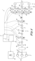
- the compressed air is routed through the network 4 of pipelines 5 from the compressors 6 to the consumers 7.
- This network 4 is in most cases a very complex network of pipelines 5.
- the gas network 1 may also be provided with a pressure vessel 8, with all compressors 6 in front of this pressure vessel 8.
- the pressure 9b in the pressure vessel is preferably also measured to correct the "mass in - mass out" principle for large, concentrated volumes.
- pressure sensors 9b can also be provided.
- number of flow sensors 9a is not limiting for the invention.
- sensors 9a, 9b may be used to determine one or more of the following physical parameters of the gas: differential pressure, temperature, humidity, gas velocity and the like.
- sensors 9a and 9b which can measure the physical parameters of the gas
- sensors 9c there are also a number of sensors 9c, or 'state sensors 9c', which are located at the relief valves 10.
- the sensors 9c are part of the relief valve 10.
- the method is the same, taking into account of course that leaks now introduce ambient air into the gas network 1.
- smaller thresholds will be set to generate an alarm.
Landscapes
- Engineering & Computer Science (AREA)
- Physics & Mathematics (AREA)
- General Engineering & Computer Science (AREA)
- Mechanical Engineering (AREA)
- General Physics & Mathematics (AREA)
- Fluid Mechanics (AREA)
- Health & Medical Sciences (AREA)
- Artificial Intelligence (AREA)
- Business, Economics & Management (AREA)
- Automation & Control Theory (AREA)
- Analytical Chemistry (AREA)
- Software Systems (AREA)
- Medical Informatics (AREA)
- Chemical & Material Sciences (AREA)
- Evolutionary Computation (AREA)
- Computer Vision & Pattern Recognition (AREA)
- Economics (AREA)
- General Health & Medical Sciences (AREA)
- Water Supply & Treatment (AREA)
- Public Health (AREA)
- Human Resources & Organizations (AREA)
- Marketing (AREA)
- Primary Health Care (AREA)
- Strategic Management (AREA)
- Tourism & Hospitality (AREA)
- General Business, Economics & Management (AREA)
- Theoretical Computer Science (AREA)
- Acoustics & Sound (AREA)
- Examining Or Testing Airtightness (AREA)
- Filling Or Discharging Of Gas Storage Vessels (AREA)
Claims (14)
- Verfahren zum Erkennen und Quantifizieren von Lecks (13) in einem Gasnetz (1) unter Druck oder Vakuum, wobei das Gasnetz (1) umfasst:- eine oder mehrere Quellen (6) von Druckgas oder Vakuum;- einen oder mehrere Verbraucher (7) oder Verbraucherbereiche von Druckgas- oder Vakuumanwendungen;- Rohrleitungen oder ein Rohrleitungsnetz (5) zum Transportieren des Gases oder Vakuums von den Quellen (6) zu den Verbrauchern (7), Verbraucherbereichen oder Anwendungen;- eine Vielzahl von Sensoren (9a, 9b), die einen oder eine Vielzahl von physikalischen Parametern des Gases zu unterschiedlichen Zeiten und an unterschiedlichen Orten im Gasnetz (1) bestimmen;dadurch gekennzeichnet, dass das Gasnetz (1) weiter mit einer Anzahl von steuerbaren oder einstellbaren Entlastungsventilen (10) versehen ist und dass das Verfahren die folgenden Schritte umfasst:- eine Trainingsphase (16), in der ein mathematisches Modell zwischen den Messungen einer ersten Gruppe von Sensoren (9a, 9b) und einer zweiten Gruppe von Sensoren (9a, 9b), umfassend eine Vielzahl von Drucksensoren (9b), möglicherweise eine Anzahl von Durchflusssensoren (9a) und möglicherweise eine Anzahl von Zustandssensoren (9c) an unterschiedlichen Orten im Gasnetz (1), basierend auf unterschiedlichen Messungen dieser Sensoren (9a, 9b) erstellt wird, wobei die zweite Gruppe von Sensoren eine Vielzahl von Zustandssensoren (9c) an unterschiedlichen Orten im Gasnetz (1) umfasst, wobei ein Sensor aus der ersten Gruppe nicht in der zweiten Gruppe vorliegt und umgekehrt, in der die einstellbaren Entlastungsventile (10) in einer vorbestimmten Reihenfolge und gemäß gut entworfenen Szenarien zum Erzeugen von Lecks (13) gesteuert werden;- eine Betriebsphase (17), in der das zwischen den Messungen der ersten Gruppe von Sensoren (9a, 9b) und der zweiten Gruppe von Sensoren (9a, 9b) erstellte mathematische Modell verwendet wird, um Lecks (13) im Gasnetz (1) zu erkennen, zu lokalisieren und zu quantifizieren;wobei die Betriebsphase (17) die folgenden Schritte umfasst:- Steuern der Entlastungsventile in einer vorbestimmten Reihenfolge und gemäß gut entworfenen Szenarien;- Auslesen der ersten Gruppe von Sensoren (9a, 9b);- basierend auf diesen ausgelesenen Messungen, Berechnen oder Bestimmen des Werts der zweiten Gruppe von Sensoren (9a, 9b) mit Hilfe des mathematischen Modells;- Vergleichen der berechneten oder bestimmten Werte der zweiten Gruppe von Sensoren (9a, 9b) mit den ausgelesenen Werten der zweiten Gruppe von Sensoren (9a, 9b) und Bestimmen der Differenz zwischen ihnen;- Bestimmen, ob ein Leck (13) im Gasnetz (1) vorliegt, auf der Basis der vorgenannten Differenz und irgendeiner ihrer Ableitungen, umfassend eine mathematische Größe, die aus der Differenz extrahierbar ist;- Erzeugen eines Alarms, wenn ein Leck (13) erkannt wird und/oder Generieren einer Leck-Rate und/oder Generieren der entsprechenden Leck-Kosten sowie eines beliebigen Orts, wenn ein Leck (13) erkannt wird.
- Verfahren nach Anspruch 1, dadurch gekennzeichnet, dass zumindest ein Teil der Durchflusssensoren (9a) in der Nähe der Entlastungsventile (10) platziert werden, so dass die Durchflussrate der Entlastungsventile (10) gemessen werden kann.
- Verfahren nach einem der vorstehenden Ansprüche, dadurch gekennzeichnet, dass das Verfahren für die Trainingsphase (16) eine Anlaufphase (15) umfasst, in der die vorgenannten Sensoren (9a, 9b) vor Gebrauch kalibriert werden.
- Verfahren nach einem der vorstehenden Ansprüche, dadurch gekennzeichnet, dass die Betriebsphase (17) vorübergehend unterbrochen oder zu bestimmten Zeitpunkten gestoppt wird, wonach die Trainingsphase (16) fortgesetzt wird, um das mathematische Modell zwischen den Messungen verschiedener Sensoren (9a, 9b) neu zu definieren, bevor die Betriebsphase (17) erneut gestartet wird.
- Verfahren nach einem der vorstehenden Ansprüche, dadurch gekennzeichnet, dass die Schritte der Betriebsphase (17) in einem bestimmten Zeitintervall sequentiell wiederholt werden.
- Verfahren nach einem der vorstehenden Ansprüche, dadurch gekennzeichnet, dass in der Nähe jedes Entlastungsventils (10) im Gasnetz (1) ein Sensor (9a, 9b) vorgesehen ist und/oder umgekehrt.
- Verfahren nach einem der vorstehenden Ansprüche, dadurch gekennzeichnet, dass das mathematische Modell ein Black-Box-Modell ist.
- Verfahren nach einem der vorstehenden Ansprüche, dadurch gekennzeichnet, dass das vorgenannte mathematische Modell die Form einer Matrix und/oder einer nichtlinearen Vektorfunktion mit Parametern oder Konstanten annimmt, wobei die Änderungen der Ausgabe oder "Ziele" des mathematischen Modells während der Betriebsphase (17) verfolgt werden.
- Verfahren nach einem der vorstehenden Ansprüche, dadurch gekennzeichnet, dass das Gasnetz (1) weiter mit einem oder einer Vielzahl Sensoren (9c) versehen ist, die den Zustand eines oder einer Vielzahl von Entlastungsventilen (10) registrieren können und/oder dass das Gasnetz (1) weiter mit einem oder einer Vielzahl von Differenzdrucksensoren (9d) versehen ist.
- Gasnetz unter Druck oder Vakuum, wobei das Gasnetz (1) zumindest ausgestattet ist mit:- einer oder mehreren Quellen (6) von Druckgas oder Vakuum;- einem oder mehreren Verbrauchern (7) oder Verbraucherbereichen von Druckgas- oder Vakuumanwendungen;- Rohrleitungen oder einem Rohrleitungsnetz (5) zum Transportieren des Gases oder Vakuums von den Quellen (6) zu den Verbrauchern (7) oder Verbraucherbereichen;- einer Vielzahl von Sensoren (9a, 9b), die einen oder mehrere physikalische Parameter des Druckgases zu unterschiedlichen Zeiten und an unterschiedlichen Orten innerhalb des Gasnetzes (1) liefern;dadurch gekennzeichnet, dass das Gasnetz (1) weiter versehen ist mit:- einer Anzahl von steuerbaren oder einstellbaren Entlastungsventilen (10);- einem oder einer Vielzahl von Sensoren (9c), die den Zustand oder Status eines oder einer Vielzahl von Entlastungsventilen (10) registrieren können;- einer Datenerfassungssteuereinheit (11) zur Sammlung von Daten von den Sensoren (9a, 9b, 9c) und zum Steuern oder Einstellen der vorgenannten Entlastungsventile;- einer Recheneinheit (12) zur Durchführung des Verfahrens nach einem der vorstehenden Ansprüche.
- Gasnetz nach Anspruch 10, dadurch gekennzeichnet, dass in der Nähe jedes Entlastungsventils (10) im Gasnetz (1) ein Sensor (9a, 9b, 9c) vorgesehen ist und/oder umgekehrt.
- Gasnetz nach einem der vorstehenden Ansprüche 10 bis 11, dadurch gekennzeichnet, dass das Gasnetz (1) weiter mit einem Monitor (14) versehen ist, um Lecks, Leck-Raten, Leck-Kosten und einen möglichen Orte (13) anzuzeigen oder zu signalisieren.
- Gasnetz nach einem der vorstehenden Ansprüche 10 bis 12, dadurch gekennzeichnet, dass das Gasnetz (1) weiter mit einem oder einer Vielzahl von Sensoren (9c) versehen ist, die den Zustand oder Status von einem oder einer Vielzahl von Entlastungsventilen (10) registrieren können und/oder dass das Gasnetz (1) weiter mit einem oder einer Vielzahl von Differenzdrucksensoren (9d) versehen ist.
- Gasnetz nach einem der vorstehenden Ansprüche 10 bis 13, dadurch gekennzeichnet, dass die Recheneinheit (12) eine Cloud-basierte Recheneinheit (12) ist, die mit dem Gasnetz (1) verbunden ist, entweder kabellos oder nicht.
Applications Claiming Priority (3)
| Application Number | Priority Date | Filing Date | Title |
|---|---|---|---|
| BE20185861A BE1026848B1 (nl) | 2018-12-07 | 2018-12-07 | Gasnetwerk en werkwijze voor het detecteren van lekken in een gasnetwerk onder druk of onder vacuüm |
| EP19832191.1A EP3891486B1 (de) | 2018-12-07 | 2019-11-26 | Gasnetz und verfahren zur detektion von lecks in einem gasnetz unter druck oder unter vakuum |
| PCT/IB2019/060166 WO2020115610A1 (en) | 2018-12-07 | 2019-11-26 | Gas network and method for detecting leaks in a gas network under pressure or under vacuum |
Related Parent Applications (2)
| Application Number | Title | Priority Date | Filing Date |
|---|---|---|---|
| EP19832191.1A Division-Into EP3891486B1 (de) | 2018-12-07 | 2019-11-26 | Gasnetz und verfahren zur detektion von lecks in einem gasnetz unter druck oder unter vakuum |
| EP19832191.1A Division EP3891486B1 (de) | 2018-12-07 | 2019-11-26 | Gasnetz und verfahren zur detektion von lecks in einem gasnetz unter druck oder unter vakuum |
Publications (3)
| Publication Number | Publication Date |
|---|---|
| EP4130701A1 EP4130701A1 (de) | 2023-02-08 |
| EP4130701C0 EP4130701C0 (de) | 2025-01-29 |
| EP4130701B1 true EP4130701B1 (de) | 2025-01-29 |
Family
ID=64959036
Family Applications (2)
| Application Number | Title | Priority Date | Filing Date |
|---|---|---|---|
| EP22191262.9A Active EP4130701B1 (de) | 2018-12-07 | 2019-11-26 | Gasnetz und verfahren zur detektion von lecks in einem gasnetz unter druck oder unter vakuum |
| EP19832191.1A Active EP3891486B1 (de) | 2018-12-07 | 2019-11-26 | Gasnetz und verfahren zur detektion von lecks in einem gasnetz unter druck oder unter vakuum |
Family Applications After (1)
| Application Number | Title | Priority Date | Filing Date |
|---|---|---|---|
| EP19832191.1A Active EP3891486B1 (de) | 2018-12-07 | 2019-11-26 | Gasnetz und verfahren zur detektion von lecks in einem gasnetz unter druck oder unter vakuum |
Country Status (10)
| Country | Link |
|---|---|
| US (1) | US12001200B2 (de) |
| EP (2) | EP4130701B1 (de) |
| JP (1) | JP7374192B2 (de) |
| KR (1) | KR102876664B1 (de) |
| CN (1) | CN113412419B (de) |
| BE (1) | BE1026848B1 (de) |
| ES (2) | ES3023755T3 (de) |
| FI (1) | FI3891486T3 (de) |
| PL (1) | PL3891486T3 (de) |
| WO (1) | WO2020115610A1 (de) |
Families Citing this family (5)
| Publication number | Priority date | Publication date | Assignee | Title |
|---|---|---|---|---|
| IT202100029993A1 (it) * | 2021-11-26 | 2023-05-26 | Eni Spa | Processo e sistema integrato di monitoraggio continuo di una condotta con fluido in pressione. |
| LU504416B1 (de) * | 2023-06-06 | 2024-12-06 | Saurer Spinning Solutions Gmbh & Co Kg | Verfahren zur Ermittlung von Leckagen und/oder Verstopfungen einer Spinneinheit einer Spinnvorrichtung einer Rotor- oder Luftspinnmaschine |
| CN117366477B (zh) * | 2023-10-16 | 2026-04-14 | 中国石油天然气股份有限公司 | 一种燃气输配系统区域平衡分析预警方法及装置 |
| CN119880056B (zh) * | 2025-03-25 | 2025-06-24 | 成都秦川物联网科技股份有限公司 | 基于智慧燃气的混气站设备监测方法和物联网系统 |
| CN120848209B (zh) * | 2025-08-01 | 2026-03-24 | 辽宁国源电力科技有限公司 | 一种基于cfd的长距离输渣数值自适应控制方法 |
Family Cites Families (31)
| Publication number | Priority date | Publication date | Assignee | Title |
|---|---|---|---|---|
| US795134A (en) | 1905-04-11 | 1905-07-18 | Barton J Jones | Cylinder drainage and relief valve. |
| US4796466A (en) * | 1987-02-17 | 1989-01-10 | Ed Farmer | System for monitoring pipelines |
| US5272646A (en) * | 1991-04-11 | 1993-12-21 | Farmer Edward J | Method for locating leaks in a fluid pipeline and apparatus therefore |
| JP2642880B2 (ja) | 1994-08-26 | 1997-08-20 | 工業技術院長 | 流量計の校正方法 |
| JP3248662B2 (ja) | 1995-04-30 | 2002-01-21 | 東京瓦斯株式会社 | ガス供給系統における遠隔監視装置 |
| US6389881B1 (en) * | 1999-05-27 | 2002-05-21 | Acoustic Systems, Inc. | Method and apparatus for pattern match filtering for real time acoustic pipeline leak detection and location |
| JP4357063B2 (ja) | 2000-02-03 | 2009-11-04 | 株式会社日本自動車部品総合研究所 | 液体ポンプの吐出能力制御方法とポンプシステム |
| US7049975B2 (en) | 2001-02-02 | 2006-05-23 | Fisher Controls International Llc | Reporting regulator for managing a gas transportation system |
| DE10133294A1 (de) | 2001-07-12 | 2003-01-23 | Siemens Ag | Drosselklappenstutzen |
| JP3870814B2 (ja) | 2002-03-29 | 2007-01-24 | 株式会社デンソー | 圧縮エア監視システム |
| US7031850B2 (en) | 2004-04-16 | 2006-04-18 | Festo Ag & Co. Kg | Method and apparatus for diagnosing leakage in a fluid power system |
| US7055366B2 (en) | 2004-05-21 | 2006-06-06 | Upchurch Scientific, Inc. | Flow sensor calibration methods and apparatus |
| US20110060542A1 (en) | 2007-06-28 | 2011-03-10 | Hexagon Metrology S.P.A. | Method for determining dynamic errors in a measuring machine |
| US10352505B2 (en) | 2008-06-27 | 2019-07-16 | Exxonmobil Research And Engineering Company | Method and apparatus for real time enhancing of the operation of a fluid transport pipeline |
| DE202008013127U1 (de) | 2008-10-01 | 2009-11-12 | Boge & Co. Maschinenhandelsgesellschaft Gmbh & Co. Kg | Einrichtung zur Erfassung von Leckverlusten einer Druckluftanlage |
| BRPI1002159A8 (pt) * | 2010-04-15 | 2021-10-26 | Asel Tech Tecnologia E Automacao Ltda | Sistema integrado com a tecnologia acústica, balanço de massa e rede neural para detecção, localização e quantificação de vazamentos em dutos |
| DE202010015450U1 (de) | 2010-11-17 | 2011-02-24 | Boge & Co. Maschinenhandelsgesellschaft Gmbh & Co. Kg | Kompressor und Druckluftanlage mit mindestens zwei Kompressoren |
| DE102011078240A1 (de) * | 2011-06-28 | 2013-01-03 | Siemens Aktiengesellschaft | Leckageerkennung mittels stochastischer Massenbilanz |
| DE102013224752A1 (de) * | 2013-12-03 | 2015-06-03 | Siemens Aktiengesellschaft | Verfahren zum Detektieren von Leckagen in einem Netzwerk, Vorrichtung und Netzwerk |
| WO2015124988A1 (en) * | 2014-02-19 | 2015-08-27 | Tata Consultancy Services Limited | Leak localization in water distribution networks |
| CN103939749B (zh) * | 2014-04-28 | 2016-08-24 | 东北大学 | 基于大数据的输油管网泄漏智能自适应监控系统及方法 |
| CN104568344A (zh) * | 2014-10-09 | 2015-04-29 | 芜湖扬宇机电技术开发有限公司 | Egr管路故障检测诊断方法 |
| CA2981298A1 (en) * | 2015-04-03 | 2016-10-06 | Hydrosmart Technologies, Inc. | Autonomous identification of an anomalous aqueous stream from an aqueous source feeding multiple independent streams and remediation directive determination thereof |
| US20160356665A1 (en) | 2015-06-02 | 2016-12-08 | Umm Al-Qura University | Pipeline monitoring systems and methods |
| EP3115666A1 (de) * | 2015-07-08 | 2017-01-11 | Ulefos Esco AS | Intelligentes ventil und automatische überwachung des zustandes von leitungen unter verwendung der intelligenten ventile |
| US10352814B2 (en) * | 2015-11-10 | 2019-07-16 | Phyn Llc | Water leak detection using pressure sensing |
| US9470601B1 (en) * | 2016-01-28 | 2016-10-18 | International Business Machines Corporation | Leak localization in pipeline network |
| US11620553B2 (en) * | 2016-04-21 | 2023-04-04 | Utopus Insights, Inc. | System and method for forecasting leaks in a fluid-delivery pipeline network |
| CN106015951B (zh) * | 2016-07-07 | 2018-11-09 | 北京信息科技大学 | 一种适应多种状态变化的输气管道泄漏检测系统及方法 |
| GB2554950B (en) * | 2016-10-17 | 2019-06-05 | Univ Cape Town | Pipe leak measurement and assessment |
| WO2018106140A1 (en) | 2016-12-06 | 2018-06-14 | Siemens Aktiengesellschaft | Method for determining of a fluid supply network state |
-
2018
- 2018-12-07 BE BE20185861A patent/BE1026848B1/nl active IP Right Grant
-
2019
- 2019-11-26 EP EP22191262.9A patent/EP4130701B1/de active Active
- 2019-11-26 ES ES22191262T patent/ES3023755T3/es active Active
- 2019-11-26 CN CN201980091031.3A patent/CN113412419B/zh active Active
- 2019-11-26 KR KR1020217019658A patent/KR102876664B1/ko active Active
- 2019-11-26 EP EP19832191.1A patent/EP3891486B1/de active Active
- 2019-11-26 US US17/311,254 patent/US12001200B2/en active Active
- 2019-11-26 WO PCT/IB2019/060166 patent/WO2020115610A1/en not_active Ceased
- 2019-11-26 ES ES19832191T patent/ES2934942T3/es active Active
- 2019-11-26 PL PL19832191.1T patent/PL3891486T3/pl unknown
- 2019-11-26 FI FIEP19832191.1T patent/FI3891486T3/fi active
- 2019-11-26 JP JP2021531772A patent/JP7374192B2/ja active Active
Also Published As
| Publication number | Publication date |
|---|---|
| US20220026893A1 (en) | 2022-01-27 |
| JP2022512112A (ja) | 2022-02-02 |
| KR102876664B1 (ko) | 2025-10-24 |
| BE1026848A1 (nl) | 2020-07-02 |
| EP3891486B1 (de) | 2022-10-05 |
| EP4130701C0 (de) | 2025-01-29 |
| FI3891486T3 (fi) | 2023-01-13 |
| WO2020115610A1 (en) | 2020-06-11 |
| US12001200B2 (en) | 2024-06-04 |
| ES3023755T3 (en) | 2025-06-03 |
| EP4130701A1 (de) | 2023-02-08 |
| JP7374192B2 (ja) | 2023-11-06 |
| KR20210098484A (ko) | 2021-08-10 |
| CN113412419A (zh) | 2021-09-17 |
| ES2934942T3 (es) | 2023-02-28 |
| CN113412419B (zh) | 2024-05-28 |
| EP3891486A1 (de) | 2021-10-13 |
| BE1026848B1 (nl) | 2020-07-09 |
| PL3891486T3 (pl) | 2023-01-30 |
Similar Documents
| Publication | Publication Date | Title |
|---|---|---|
| EP3891486B1 (de) | Gasnetz und verfahren zur detektion von lecks in einem gasnetz unter druck oder unter vakuum | |
| EP3903018B1 (de) | Verfahren zur erkennung von lecks in einem gasnetz unter druck oder unter vakuum und gasnetz | |
| EP4123282B1 (de) | Gasnetzwerk und verfahren zur gleichzeitigen detektion von lecks und verstopfungen in einem gasnetz unter druck oder vakuum | |
| WO2020136475A1 (en) | Method for detecting leaks in a gas network under pressure or under vacuum and gas network | |
| EP4105544B1 (de) | Gasnetz und verfahren zur detektion von verstopfungen in einem gasnetz unter druck oder unter vakuum |
Legal Events
| Date | Code | Title | Description |
|---|---|---|---|
| PUAI | Public reference made under article 153(3) epc to a published international application that has entered the european phase |
Free format text: ORIGINAL CODE: 0009012 |
|
| STAA | Information on the status of an ep patent application or granted ep patent |
Free format text: STATUS: THE APPLICATION HAS BEEN PUBLISHED |
|
| AC | Divisional application: reference to earlier application |
Ref document number: 3891486 Country of ref document: EP Kind code of ref document: P |
|
| AK | Designated contracting states |
Kind code of ref document: A1 Designated state(s): AL AT BE BG CH CY CZ DE DK EE ES FI FR GB GR HR HU IE IS IT LI LT LU LV MC MK MT NL NO PL PT RO RS SE SI SK SM TR |
|
| STAA | Information on the status of an ep patent application or granted ep patent |
Free format text: STATUS: REQUEST FOR EXAMINATION WAS MADE |
|
| 17P | Request for examination filed |
Effective date: 20230209 |
|
| RBV | Designated contracting states (corrected) |
Designated state(s): AL AT BE BG CH CY CZ DE DK EE ES FI FR GB GR HR HU IE IS IT LI LT LU LV MC MK MT NL NO PL PT RO RS SE SI SK SM TR |
|
| GRAP | Despatch of communication of intention to grant a patent |
Free format text: ORIGINAL CODE: EPIDOSNIGR1 |
|
| STAA | Information on the status of an ep patent application or granted ep patent |
Free format text: STATUS: GRANT OF PATENT IS INTENDED |
|
| INTG | Intention to grant announced |
Effective date: 20240919 |
|
| GRAS | Grant fee paid |
Free format text: ORIGINAL CODE: EPIDOSNIGR3 |
|
| GRAA | (expected) grant |
Free format text: ORIGINAL CODE: 0009210 |
|
| STAA | Information on the status of an ep patent application or granted ep patent |
Free format text: STATUS: THE PATENT HAS BEEN GRANTED |
|
| AC | Divisional application: reference to earlier application |
Ref document number: 3891486 Country of ref document: EP Kind code of ref document: P |
|
| AK | Designated contracting states |
Kind code of ref document: B1 Designated state(s): AL AT BE BG CH CY CZ DE DK EE ES FI FR GB GR HR HU IE IS IT LI LT LU LV MC MK MT NL NO PL PT RO RS SE SI SK SM TR |
|
| REG | Reference to a national code |
Ref country code: GB Ref legal event code: FG4D |
|
| REG | Reference to a national code |
Ref country code: CH Ref legal event code: EP |
|
| REG | Reference to a national code |
Ref country code: DE Ref legal event code: R096 Ref document number: 602019065579 Country of ref document: DE |
|
| REG | Reference to a national code |
Ref country code: IE Ref legal event code: FG4D |
|
| U01 | Request for unitary effect filed |
Effective date: 20250226 |
|
| U07 | Unitary effect registered |
Designated state(s): AT BE BG DE DK EE FI FR IT LT LU LV MT NL PT RO SE SI Effective date: 20250324 |
|
| REG | Reference to a national code |
Ref country code: ES Ref legal event code: FG2A Ref document number: 3023755 Country of ref document: ES Kind code of ref document: T3 Effective date: 20250603 |
|
| PG25 | Lapsed in a contracting state [announced via postgrant information from national office to epo] |
Ref country code: RS Free format text: LAPSE BECAUSE OF FAILURE TO SUBMIT A TRANSLATION OF THE DESCRIPTION OR TO PAY THE FEE WITHIN THE PRESCRIBED TIME-LIMIT Effective date: 20250429 |
|
| PG25 | Lapsed in a contracting state [announced via postgrant information from national office to epo] |
Ref country code: PL Free format text: LAPSE BECAUSE OF FAILURE TO SUBMIT A TRANSLATION OF THE DESCRIPTION OR TO PAY THE FEE WITHIN THE PRESCRIBED TIME-LIMIT Effective date: 20250129 |
|
| PG25 | Lapsed in a contracting state [announced via postgrant information from national office to epo] |
Ref country code: IS Free format text: LAPSE BECAUSE OF FAILURE TO SUBMIT A TRANSLATION OF THE DESCRIPTION OR TO PAY THE FEE WITHIN THE PRESCRIBED TIME-LIMIT Effective date: 20250529 Ref country code: NO Free format text: LAPSE BECAUSE OF FAILURE TO SUBMIT A TRANSLATION OF THE DESCRIPTION OR TO PAY THE FEE WITHIN THE PRESCRIBED TIME-LIMIT Effective date: 20250429 |
|
| PG25 | Lapsed in a contracting state [announced via postgrant information from national office to epo] |
Ref country code: HR Free format text: LAPSE BECAUSE OF FAILURE TO SUBMIT A TRANSLATION OF THE DESCRIPTION OR TO PAY THE FEE WITHIN THE PRESCRIBED TIME-LIMIT Effective date: 20250129 |
|
| PG25 | Lapsed in a contracting state [announced via postgrant information from national office to epo] |
Ref country code: GR Free format text: LAPSE BECAUSE OF FAILURE TO SUBMIT A TRANSLATION OF THE DESCRIPTION OR TO PAY THE FEE WITHIN THE PRESCRIBED TIME-LIMIT Effective date: 20250430 |
|
| PG25 | Lapsed in a contracting state [announced via postgrant information from national office to epo] |
Ref country code: SM Free format text: LAPSE BECAUSE OF FAILURE TO SUBMIT A TRANSLATION OF THE DESCRIPTION OR TO PAY THE FEE WITHIN THE PRESCRIBED TIME-LIMIT Effective date: 20250129 |
|
| PG25 | Lapsed in a contracting state [announced via postgrant information from national office to epo] |
Ref country code: CZ Free format text: LAPSE BECAUSE OF FAILURE TO SUBMIT A TRANSLATION OF THE DESCRIPTION OR TO PAY THE FEE WITHIN THE PRESCRIBED TIME-LIMIT Effective date: 20250129 |
|
| PG25 | Lapsed in a contracting state [announced via postgrant information from national office to epo] |
Ref country code: SK Free format text: LAPSE BECAUSE OF FAILURE TO SUBMIT A TRANSLATION OF THE DESCRIPTION OR TO PAY THE FEE WITHIN THE PRESCRIBED TIME-LIMIT Effective date: 20250129 |
|
| REG | Reference to a national code |
Ref country code: CH Ref legal event code: U11 Free format text: ST27 STATUS EVENT CODE: U-0-0-U10-U11 (AS PROVIDED BY THE NATIONAL OFFICE) Effective date: 20251201 |
|
| PLBE | No opposition filed within time limit |
Free format text: ORIGINAL CODE: 0009261 |
|
| STAA | Information on the status of an ep patent application or granted ep patent |
Free format text: STATUS: NO OPPOSITION FILED WITHIN TIME LIMIT |
|
| U20 | Renewal fee for the european patent with unitary effect paid |
Year of fee payment: 7 Effective date: 20251126 |
|
| 26N | No opposition filed |
Effective date: 20251030 |
|
| PGFP | Annual fee paid to national office [announced via postgrant information from national office to epo] |
Ref country code: GB Payment date: 20251127 Year of fee payment: 7 |
|
| PGFP | Annual fee paid to national office [announced via postgrant information from national office to epo] |
Ref country code: CH Payment date: 20251201 Year of fee payment: 7 |
|
| PGFP | Annual fee paid to national office [announced via postgrant information from national office to epo] |
Ref country code: ES Payment date: 20251201 Year of fee payment: 7 |