EP4129896A1 - Thermoelectric conversion material, thermoelectric conversion element, and thermoelectric conversion module - Google Patents
Thermoelectric conversion material, thermoelectric conversion element, and thermoelectric conversion module Download PDFInfo
- Publication number
- EP4129896A1 EP4129896A1 EP21774921.7A EP21774921A EP4129896A1 EP 4129896 A1 EP4129896 A1 EP 4129896A1 EP 21774921 A EP21774921 A EP 21774921A EP 4129896 A1 EP4129896 A1 EP 4129896A1
- Authority
- EP
- European Patent Office
- Prior art keywords
- thermoelectric conversion
- present
- conversion material
- elements
- chemical formula
- Prior art date
- Legal status (The legal status is an assumption and is not a legal conclusion. Google has not performed a legal analysis and makes no representation as to the accuracy of the status listed.)
- Withdrawn
Links
- 238000006243 chemical reaction Methods 0.000 title claims abstract description 98
- 239000000463 material Substances 0.000 title claims abstract description 52
- 239000000126 substance Substances 0.000 claims abstract description 16
- 229910052802 copper Inorganic materials 0.000 claims abstract description 9
- 230000014509 gene expression Effects 0.000 claims description 5
- 239000010949 copper Substances 0.000 description 19
- 230000003247 decreasing effect Effects 0.000 description 13
- 239000002994 raw material Substances 0.000 description 12
- 238000005245 sintering Methods 0.000 description 10
- 239000000203 mixture Substances 0.000 description 6
- 230000000052 comparative effect Effects 0.000 description 5
- 150000001875 compounds Chemical class 0.000 description 4
- PXHVJJICTQNCMI-UHFFFAOYSA-N nickel Substances [Ni] PXHVJJICTQNCMI-UHFFFAOYSA-N 0.000 description 4
- 229910052709 silver Inorganic materials 0.000 description 4
- KTLOQXXVQYUCJU-UHFFFAOYSA-N [Cu].[Cu].[Se] Chemical compound [Cu].[Cu].[Se] KTLOQXXVQYUCJU-UHFFFAOYSA-N 0.000 description 3
- 230000000694 effects Effects 0.000 description 3
- 229910052759 nickel Inorganic materials 0.000 description 3
- 229910052763 palladium Inorganic materials 0.000 description 3
- 238000007747 plating Methods 0.000 description 3
- IRPLSAGFWHCJIQ-UHFFFAOYSA-N selanylidenecopper Chemical compound [Se]=[Cu] IRPLSAGFWHCJIQ-UHFFFAOYSA-N 0.000 description 3
- 230000005678 Seebeck effect Effects 0.000 description 2
- 229910052782 aluminium Inorganic materials 0.000 description 2
- XAGFODPZIPBFFR-UHFFFAOYSA-N aluminium Chemical compound [Al] XAGFODPZIPBFFR-UHFFFAOYSA-N 0.000 description 2
- 229910052737 gold Inorganic materials 0.000 description 2
- 229910052697 platinum Inorganic materials 0.000 description 2
- RYGMFSIKBFXOCR-UHFFFAOYSA-N Copper Chemical compound [Cu] RYGMFSIKBFXOCR-UHFFFAOYSA-N 0.000 description 1
- ZOKXTWBITQBERF-UHFFFAOYSA-N Molybdenum Chemical compound [Mo] ZOKXTWBITQBERF-UHFFFAOYSA-N 0.000 description 1
- 230000005679 Peltier effect Effects 0.000 description 1
- BQCADISMDOOEFD-UHFFFAOYSA-N Silver Chemical compound [Ag] BQCADISMDOOEFD-UHFFFAOYSA-N 0.000 description 1
- 238000005219 brazing Methods 0.000 description 1
- 229910017052 cobalt Inorganic materials 0.000 description 1
- 239000010941 cobalt Substances 0.000 description 1
- GUTLYIVDDKVIGB-UHFFFAOYSA-N cobalt atom Chemical compound [Co] GUTLYIVDDKVIGB-UHFFFAOYSA-N 0.000 description 1
- 229910003460 diamond Inorganic materials 0.000 description 1
- 239000010432 diamond Substances 0.000 description 1
- 230000005611 electricity Effects 0.000 description 1
- 238000004070 electrodeposition Methods 0.000 description 1
- 238000011156 evaluation Methods 0.000 description 1
- 238000002474 experimental method Methods 0.000 description 1
- 239000007769 metal material Substances 0.000 description 1
- 229910052750 molybdenum Inorganic materials 0.000 description 1
- 239000011733 molybdenum Substances 0.000 description 1
- 238000010248 power generation Methods 0.000 description 1
- 239000004332 silver Substances 0.000 description 1
- 229910000679 solder Inorganic materials 0.000 description 1
- WFKWXMTUELFFGS-UHFFFAOYSA-N tungsten Chemical compound [W] WFKWXMTUELFFGS-UHFFFAOYSA-N 0.000 description 1
- 229910052721 tungsten Inorganic materials 0.000 description 1
- 239000010937 tungsten Substances 0.000 description 1
- 238000005303 weighing Methods 0.000 description 1
Images

Classifications
-
- C—CHEMISTRY; METALLURGY
- C01—INORGANIC CHEMISTRY
- C01B—NON-METALLIC ELEMENTS; COMPOUNDS THEREOF; METALLOIDS OR COMPOUNDS THEREOF NOT COVERED BY SUBCLASS C01C
- C01B19/00—Selenium; Tellurium; Compounds thereof
- C01B19/002—Compounds containing, besides selenium or tellurium, more than one other element, with -O- and -OH not being considered as anions
-
- H—ELECTRICITY
- H10—SEMICONDUCTOR DEVICES; ELECTRIC SOLID-STATE DEVICES NOT OTHERWISE PROVIDED FOR
- H10N—ELECTRIC SOLID-STATE DEVICES NOT OTHERWISE PROVIDED FOR
- H10N10/00—Thermoelectric devices comprising a junction of dissimilar materials, i.e. devices exhibiting Seebeck or Peltier effects
- H10N10/10—Thermoelectric devices comprising a junction of dissimilar materials, i.e. devices exhibiting Seebeck or Peltier effects operating with only the Peltier or Seebeck effects
-
- H—ELECTRICITY
- H10—SEMICONDUCTOR DEVICES; ELECTRIC SOLID-STATE DEVICES NOT OTHERWISE PROVIDED FOR
- H10N—ELECTRIC SOLID-STATE DEVICES NOT OTHERWISE PROVIDED FOR
- H10N10/00—Thermoelectric devices comprising a junction of dissimilar materials, i.e. devices exhibiting Seebeck or Peltier effects
- H10N10/80—Constructional details
-
- H—ELECTRICITY
- H10—SEMICONDUCTOR DEVICES; ELECTRIC SOLID-STATE DEVICES NOT OTHERWISE PROVIDED FOR
- H10N—ELECTRIC SOLID-STATE DEVICES NOT OTHERWISE PROVIDED FOR
- H10N10/00—Thermoelectric devices comprising a junction of dissimilar materials, i.e. devices exhibiting Seebeck or Peltier effects
- H10N10/80—Constructional details
- H10N10/85—Thermoelectric active materials
- H10N10/851—Thermoelectric active materials comprising inorganic compositions
- H10N10/852—Thermoelectric active materials comprising inorganic compositions comprising tellurium, selenium or sulfur
-
- C—CHEMISTRY; METALLURGY
- C01—INORGANIC CHEMISTRY
- C01P—INDEXING SCHEME RELATING TO STRUCTURAL AND PHYSICAL ASPECTS OF SOLID INORGANIC COMPOUNDS
- C01P2006/00—Physical properties of inorganic compounds
- C01P2006/60—Optical properties, e.g. expressed in CIELAB-values
Definitions
- the present invention relates to a thermoelectric conversion material containing Cu and Se as main components, a thermoelectric conversion element made of the thermoelectric conversion material, and a thermoelectric conversion module.
- thermoelectric conversion element made of a thermoelectric conversion material is an electronic element that enables mutual conversion between heat and electricity by the Seebeck effect and the Peltier effect.
- the Seebeck effect is a phenomenon in which an electromotive force is generated when a temperature difference is generated between both ends of the thermoelectric conversion material, and the thermal energy is converted into electric energy. Such electromotive force is determined by the characteristics of the thermoelectric conversion material. In recent years, thermoelectric power generation utilizing this effect has been actively developed.
- thermoelectric conversion element has a structure in which electrodes are each formed on one end side and the other end side of the thermoelectric conversion material.
- thermoelectric conversion element a thermoelectric conversion material
- PF power factor represented by Expression (1)
- V/K Seebeck coefficient
- S/m electrical conductivity
- thermoelectric conversion material for example, copper selenide containing Cu and Se as main components has been proposed as shown in Patent Documents 1 to 4.
- thermoelectric conversion materials used in low voltage and high current applications low electrical resistivity is required.
- the Seebeck coefficient and the power factor (PF) are decreased, and thus there is a risk that the thermoelectric conversion efficiency is decreased.
- the present invention has been made in consideration of the above-described circumstances, and an object of the present invention is to provide a thermoelectric conversion material having a low electrical resistivity, a sufficiently high power factor, and excellent thermoelectric conversion efficiency, as well as a thermoelectric conversion element and a thermoelectric conversion module, in which this thermoelectric conversion material is used.
- thermoelectric conversion material of the present invention is characterized by containing Cu and Se as main components; an element M including one or two or more elements selected from Group 10 elements and Group 11 elements excluding Cu; and optional element of Te, where the thermoelectric conversion material is represented by the following chemical formula, Chemical Formula: Cu x Se (1-y) Te y M z 1.95 ⁇ x ⁇ 2.05 0 ⁇ y ⁇ 0.1 0.002 ⁇ z ⁇ 0.03 .
- thermoelectric conversion material having this configuration, since the thermoelectric conversion material contains, in addition to Cu and Se, an element M including one or two or more elements selected from Group 10 elements (Ni, Pt, Pd, and the like) and Group 11 elements (Au, Ag, and the like) excluding Cu, and further contains Te, as necessary, the electrical resistivity is decreased. However, the Seebeck coefficient is not decreased more than necessary. As a result, the power factor (PF), which is an indicator of the thermoelectric conversion efficiency, is excellent, and the thermoelectric conversion efficiency is high even in low voltage and high current applications.
- PF power factor
- thermoelectric conversion material of the present invention it is preferable that the following expressions are satisfied in the above chemical formula, 1.95 ⁇ x ⁇ 2.05 0.05 ⁇ y ⁇ 0.1 0.002 ⁇ z ⁇ 0.01 .
- the electrical resistivity is further decreased, and the power factor (PF) is excellent since the followings are satisfied in the above chemical formula; 1.95 ⁇ x ⁇ 2.05, 0.05 ⁇ y ⁇ 0.1, and 0.002 ⁇ z ⁇ 0.01.
- thermoelectric conversion element of the present invention is characterized by including the thermoelectric conversion material described above and electrodes each joined to a first surface and a second surface of the thermoelectric conversion material.
- thermoelectric conversion element having this configuration, since the thermoelectric conversion material having a low electrical resistivity and an excellent power factor (PF) is provided, the thermoelectric conversion performance is stable, whereby the reliability is excellent in low voltage and high current applications.
- PF power factor
- thermoelectric conversion module of the present invention is characterized by including the thermoelectric conversion element described above and terminals each joined to the electrodes of the thermoelectric conversion element.
- thermoelectric conversion module having this configuration, since the thermoelectric conversion element described above is provided, the electrical resistivity is low, the power factor (PF) is excellent, and the thermoelectric conversion performance is stable, whereby the reliability is excellent in low voltage and high current applications.
- thermoelectric conversion material having a low electrical resistivity, a sufficiently high power factor, and excellent thermoelectric conversion efficiency, as well as a thermoelectric conversion element and a thermoelectric conversion module, in which this thermoelectric conversion material is used.
- thermoelectric conversion material a thermoelectric conversion element, and a thermoelectric conversion module according to an embodiment of the present invention will be described with reference to the attached drawings.
- Each embodiment to be described below is specifically described for a better understanding of the gist of the invention and does not limit the present invention unless otherwise specified.
- drawings used in the following description for convenience, a portion that is the main part may be enlarged in some cases in order to make the features of the present invention easy to understand, and the dimensional ratio or the like of each component is not always the same as an actual one.
- Fig. 1 shows a thermoelectric conversion material 11 according to an embodiment of the present invention, a thermoelectric conversion element 10 using the thermoelectric conversion material 11, and a thermoelectric conversion module 1.
- thermoelectric conversion element 10 includes a thermoelectric conversion material 11 according to the present embodiment, and electrodes 18a and 18b formed on a first surface 11a and a second surface 11b of the thermoelectric conversion material 11.
- thermoelectric conversion module 1 includes terminals 19a and 19b each joined to the electrodes 18a and 18b of the thermoelectric conversion element 10 described above.
- Nickel, silver, cobalt, tungsten, molybdenum, or the like is used in the electrodes 18a and 18b.
- the electrodes 18a and 18b can be formed by energized sintering, plating, electrodeposition, or the like.
- the terminals 19a and 19b are formed of a metal material having excellent conductivity, for example, a plate material such as copper or aluminum. In the present embodiment, a rolled aluminum plate is used. Further, the thermoelectric conversion element 10 (the electrodes 18a and 18b) can be joined to the terminals 19a and 19b with an Ag joining material or solder by Ag brazing, or by Ag plating, Au plating, or the like of the electrodes 18a and 18b.
- thermoelectric conversion material 11 contains Cu and Se as main components and further contains optional element of Te, and an element M including one or two or more elements selected from Group 10 elements and Group 11 elements excluding Cu, where the thermoelectric conversion material is represented by the following chemical formula, Chemical Formula: Cu x Se (1-y) Te y M z 1.95 ⁇ x ⁇ 2.05 0 ⁇ y ⁇ 0.1 0.002 ⁇ z ⁇ 0.03 .
- thermoelectric conversion material 11 it is preferable that x, y, and z in the above chemical formula are each in the following range. 1.95 ⁇ x ⁇ 2.05 0.05 ⁇ y ⁇ 0.1 0.002 ⁇ z ⁇ 0.01 .
- thermoelectric conversion material 11 contains copper selenide (Cu 2 Se) that contains a trace amount of an element M including one or two or more elements selected from Group 10 elements and Group 11 elements excluding Cu, and optional element of Te.
- Cu 2 Se copper selenide
- thermoelectric conversion material made of copper selenide.
- thermoelectric conversion material made of copper selenide even in a case where a part of Se is replaced with Te.
- thermoelectric conversion material 11 can be produced by weighing and mixing each of a Cu raw material, a Se raw material, a Te raw material, and a raw material containing the element M, and sintering the obtained mixture. It is noted that a Cu raw material or a Se raw material, which contains the element M and Te, may be used since trace amounts of the element M and Te are to be contained.
- thermoelectric conversion material 11 having such a configuration as described above, since the thermoelectric conversion material contains, in addition to Cu and Se, an element M including one or two or more elements selected from Group 10 elements and Group 11 elements excluding Cu, and further contains Te, as necessary, the electrical resistivity is decreased. However, the Seebeck coefficient is not decreased more than necessary. As a result, the power factor (PF), which is an indicator of the thermoelectric conversion efficiency, is excellent, and the thermoelectric conversion efficiency is high even in low voltage and high current applications.
- PF power factor
- the electrical resistivity is further decreased, and the power factor (PF) is excellent in a case where the following expressions are satisfied in the above chemical formula; 1.95 ⁇ x ⁇ 2.05, 0.05 ⁇ y ⁇ 0.1, and 0.002 ⁇ z ⁇ 0.01.
- thermoelectric conversion module having a structure as shown in Fig. 1
- the present embodiment is not limited to this, and in a case where the thermoelectric conversion material of the present invention is used, there are no particular limitations on the structure and arrangement of electrodes or terminals.
- Cu 2 Se copper selenide
- Te a compound containing Te
- element M a compound containing the element M
- the obtained mixture was pressed to be pelletized at 4 GPa for 1 minute with a hand press and subjected to primary sintering using a tube furnace.
- the conditions for the primary sintering were a sintering temperature of 100°C to 200°C in an Ar atmosphere and a holding time of 3 hours at the sintering temperature.
- the obtained sintered body was weighed and subjected to secondary sintering using a tube furnace.
- the conditions for the secondary sintering were a sintering temperature of 850°C in an Ar atmosphere and a holding time of 3 hours at the sintering temperature.
- thermoelectric conversion material having the composition shown in Table 1 was obtained.
- thermoelectric conversion material obtained as described above.
- the evaluation results are shown in Figs. 2 to 4 .
- the electrical resistivity R and the Seebeck coefficient S were measured by ZEM-3 manufactured by ADVANCE RIKO, Inc.
- PF The power factor (PF) was determined according to Expression (1).
- PF S 2 / R
- S Seebeck coefficient (V/K)
- R electrical resistivity ( ⁇ m)
- Composition (atomic%) Cu x Se (1-y) Te y M z Cu Se Te Element M x y z Present Invention
- Example 1 66.1 32.9 0.10 0.84 2.0 0.003 0.025 Present Invention
- Example 2 66.1 33.0 0.00 0.85 2.0 0.000 0.026 Present Invention
- Example 3 66.0 33.0 0.00 0.99 2.0 0.000 0.030
- Example 4 66.7 31.0 2.23 0.08 2.0 0.067 0.002 Present Invention
- Example 5 66.7 30.7 2.49 0.09 2.0 0.075 0.003
- Present Invention Examples 1 to 6 are shown as (1) to (6), and the comparative example is shown as "Ref.”.
- thermoelectric conversion material having a low electrical resistivity, a sufficiently high power factor, and excellent thermoelectric conversion efficiency, as well as a thermoelectric conversion element and a thermoelectric conversion module, in which this thermoelectric conversion material is used.
Landscapes
- Chemical & Material Sciences (AREA)
- Inorganic Chemistry (AREA)
- Organic Chemistry (AREA)
- Powder Metallurgy (AREA)
- Compositions Of Oxide Ceramics (AREA)
Abstract
Chemical Formula: CuxSe(1-y)TeyMz,

Description
- The present invention relates to a thermoelectric conversion material containing Cu and Se as main components, a thermoelectric conversion element made of the thermoelectric conversion material, and a thermoelectric conversion module.
- Priority is claimed on
Japanese Patent Application No. 2020-057017, filed March 27, 2020 - A thermoelectric conversion element made of a thermoelectric conversion material is an electronic element that enables mutual conversion between heat and electricity by the Seebeck effect and the Peltier effect. The Seebeck effect is a phenomenon in which an electromotive force is generated when a temperature difference is generated between both ends of the thermoelectric conversion material, and the thermal energy is converted into electric energy. Such electromotive force is determined by the characteristics of the thermoelectric conversion material. In recent years, thermoelectric power generation utilizing this effect has been actively developed.
- The above-described thermoelectric conversion element has a structure in which electrodes are each formed on one end side and the other end side of the thermoelectric conversion material.
- As an indicator that indicates the characteristics of such a thermoelectric conversion element (a thermoelectric conversion material), for example, a power factor (PF) represented by Expression (1) is used.

- As the above-described thermoelectric conversion material, for example, copper selenide containing Cu and Se as main components has been proposed as shown in
Patent Documents 1 to 4. -
- [Patent Document 1]
Japanese Patent No. 6216064 - [Patent Document 2]
Japanese Patent No. 6266099 - [Patent Document 3]
Japanese Patent No. 6460351 - [Patent Document 4]
Japanese Patent No. 6460352 - By the way, in thermoelectric conversion materials used in low voltage and high current applications, low electrical resistivity is required. However, in a case where the electrical resistivity is decreased, the Seebeck coefficient and the power factor (PF) are decreased, and thus there is a risk that the thermoelectric conversion efficiency is decreased.
- The present invention has been made in consideration of the above-described circumstances, and an object of the present invention is to provide a thermoelectric conversion material having a low electrical resistivity, a sufficiently high power factor, and excellent thermoelectric conversion efficiency, as well as a thermoelectric conversion element and a thermoelectric conversion module, in which this thermoelectric conversion material is used.
- In order to solve the above problems, the thermoelectric conversion material of the present invention is characterized by containing Cu and Se as main components; an element M including one or two or more elements selected from
Group 10 elements andGroup 11 elements excluding Cu; and optional element of Te, where the thermoelectric conversion material is represented by the following chemical formula,
Chemical Formula: CuxSe(1-y)TeyMz



- According to the thermoelectric conversion material having this configuration, since the thermoelectric conversion material contains, in addition to Cu and Se, an element M including one or two or more elements selected from
Group 10 elements (Ni, Pt, Pd, and the like) andGroup 11 elements (Au, Ag, and the like) excluding Cu, and further contains Te, as necessary, the electrical resistivity is decreased. However, the Seebeck coefficient is not decreased more than necessary. As a result, the power factor (PF), which is an indicator of the thermoelectric conversion efficiency, is excellent, and the thermoelectric conversion efficiency is high even in low voltage and high current applications. - Here, in the thermoelectric conversion material of the present invention, it is preferable that the following expressions are satisfied in the above chemical formula,


- In this case, the electrical resistivity is further decreased, and the power factor (PF) is excellent since the followings are satisfied in the above chemical formula; 1.95 ≤ x < 2.05, 0.05 ≤ y ≤ 0.1, and 0.002 ≤ z ≤ 0.01.
- The thermoelectric conversion element of the present invention is characterized by including the thermoelectric conversion material described above and electrodes each joined to a first surface and a second surface of the thermoelectric conversion material.
- According to the thermoelectric conversion element having this configuration, since the thermoelectric conversion material having a low electrical resistivity and an excellent power factor (PF) is provided, the thermoelectric conversion performance is stable, whereby the reliability is excellent in low voltage and high current applications.
- The thermoelectric conversion module of the present invention is characterized by including the thermoelectric conversion element described above and terminals each joined to the electrodes of the thermoelectric conversion element.
- According to the thermoelectric conversion module having this configuration, since the thermoelectric conversion element described above is provided, the electrical resistivity is low, the power factor (PF) is excellent, and the thermoelectric conversion performance is stable, whereby the reliability is excellent in low voltage and high current applications.
- According to the present invention, it is possible to provide a thermoelectric conversion material having a low electrical resistivity, a sufficiently high power factor, and excellent thermoelectric conversion efficiency, as well as a thermoelectric conversion element and a thermoelectric conversion module, in which this thermoelectric conversion material is used.
-
-
Fig. 1 is a cross-sectional view of a thermoelectric conversion material, a thermoelectric conversion element, and a thermoelectric conversion module according to an embodiment of the present invention. -
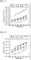
Fig. 2 is a graph showing the relationship between electrical resistivity and the temperature in Examples. -
Fig. 3 is a graph showing the relationship between the Seebeck coefficient and the temperature in Examples. -
Fig. 4 is a graph showing the relationship between the power factor and the temperature in Examples. - Hereinafter, a thermoelectric conversion material, a thermoelectric conversion element, and a thermoelectric conversion module according to an embodiment of the present invention will be described with reference to the attached drawings. Each embodiment to be described below is specifically described for a better understanding of the gist of the invention and does not limit the present invention unless otherwise specified. In addition, in the drawings used in the following description, for convenience, a portion that is the main part may be enlarged in some cases in order to make the features of the present invention easy to understand, and the dimensional ratio or the like of each component is not always the same as an actual one.
-
Fig. 1 shows athermoelectric conversion material 11 according to an embodiment of the present invention, athermoelectric conversion element 10 using thethermoelectric conversion material 11, and athermoelectric conversion module 1. - The
thermoelectric conversion element 10 includes athermoelectric conversion material 11 according to the present embodiment, andelectrodes first surface 11a and asecond surface 11b of thethermoelectric conversion material 11. - Further, the
thermoelectric conversion module 1 includesterminals electrodes thermoelectric conversion element 10 described above. - Nickel, silver, cobalt, tungsten, molybdenum, or the like is used in the
electrodes electrodes - The
terminals electrodes terminals electrodes - In addition, the
thermoelectric conversion material 11 according to the present embodiment contains Cu and Se as main components and further contains optional element of Te, and an element M including one or two or more elements selected fromGroup 10 elements andGroup 11 elements excluding Cu,
where the thermoelectric conversion material is represented by the following chemical formula,
Chemical Formula: CuxSe(1-y)TeyMz



- Here, in the
thermoelectric conversion material 11 according to the present embodiment, it is preferable that x, y, and z in the above chemical formula are each in the following range.


- That is, the
thermoelectric conversion material 11 according to the present embodiment contains copper selenide (Cu2Se) that contains a trace amount of an element M including one or two or more elements selected fromGroup 10 elements andGroup 11 elements excluding Cu, and optional element of Te. - Since trace amounts of the element M and Te are contained, the electrical resistivity is decreased. Further, even in a case where trace amounts of the element M and Te are added to copper selenide (Cu2Se), the power factor is not significantly affected.
- Here, in a case of setting x to 1.95 ≤ x < 2.05 in the above chemical formula, it is possible to secure the basic characteristics as a thermoelectric conversion material made of copper selenide.
- In addition, in a case of setting y to 0 ≤ y ≤ 0.1, preferably 0.05 ≤ x ≤ 0.1 in the above chemical formula, it is possible to secure the basic properties as a thermoelectric conversion material made of copper selenide even in a case where a part of Se is replaced with Te.
- Further, in a case of setting z to 0.002 ≤ z ≤ 0.03, preferably 0.002 ≤ z ≤ 0.01 in the above chemical formula, it is possible to decrease the electrical resistivity without decreasing the Seebeck coefficient more than necessary.
- The
thermoelectric conversion material 11 according to the present embodiment can be produced by weighing and mixing each of a Cu raw material, a Se raw material, a Te raw material, and a raw material containing the element M, and sintering the obtained mixture. It is noted that a Cu raw material or a Se raw material, which contains the element M and Te, may be used since trace amounts of the element M and Te are to be contained. - According to the
thermoelectric conversion material 11 according to the present embodiment having such a configuration as described above, since the thermoelectric conversion material contains, in addition to Cu and Se, an element M including one or two or more elements selected fromGroup 10 elements andGroup 11 elements excluding Cu, and further contains Te, as necessary, the electrical resistivity is decreased. However, the Seebeck coefficient is not decreased more than necessary. As a result, the power factor (PF), which is an indicator of the thermoelectric conversion efficiency, is excellent, and the thermoelectric conversion efficiency is high even in low voltage and high current applications. - Further, in the present embodiment, the electrical resistivity is further decreased, and the power factor (PF) is excellent in a case where the following expressions are satisfied in the above chemical formula; 1.95 ≤ x < 2.05, 0.05 ≤ y ≤ 0.1, and 0.002 ≤ z ≤ 0.01.
- Although the embodiment of the present invention has been described above, the present invention is not limited thereto and can be appropriately modified without departing from the technical idea of the invention.
- For example, in the present embodiment, although a description has been made such that a thermoelectric conversion module having a structure as shown in
Fig. 1 is constituted, the present embodiment is not limited to this, and in a case where the thermoelectric conversion material of the present invention is used, there are no particular limitations on the structure and arrangement of electrodes or terminals. - Hereinafter, the results of experiments carried out to confirm the effect of the present invention will be described.
- As shown in Table 1, a Cu raw material, a Se raw material, a Te raw material, and a raw material containing the element M were weighed and mixed.
- Specifically, copper selenide (Cu2Se), a compound containing Te, and a compound containing the element M were used to obtain a mixture satisfying the composition shown in Table 1.
- It is noted that in Present Invention Examples 1 to 3, a compound containing Pd and Ag was used as the raw material containing the element M, and in Present Invention Examples 4 to 6, a compound containing Ag was used as the raw material containing the element M.
- The obtained mixture was pressed to be pelletized at 4 GPa for 1 minute with a hand press and subjected to primary sintering using a tube furnace. The conditions for the primary sintering were a sintering temperature of 100°C to 200°C in an Ar atmosphere and a holding time of 3 hours at the sintering temperature. Then, the obtained sintered body was weighed and subjected to secondary sintering using a tube furnace. The conditions for the secondary sintering were a sintering temperature of 850°C in an Ar atmosphere and a holding time of 3 hours at the sintering temperature.
- Finally, the obtained sintered body was cut to a predetermined size using a diamond band saw, and the surface of the cut sintered body was polished with sandpaper of various grit size. As a result, a thermoelectric conversion material having the composition shown in Table 1 was obtained.
- The electrical resistivity R, the Seebeck coefficient, and the power factor PF at various temperatures were evaluated for the thermoelectric conversion material obtained as described above. The evaluation results are shown in
Figs. 2 to 4 . - In
Figs. 2 to 4 , (1) is Present Invention Example 1, (2) is Present Invention Example 2, (3) is Present Invention Example 3, (4) is Present Invention Example 4, and (5) is Present Invention Example 5, (6) is Present Invention Example 6, and Ref. is the comparative example. - The electrical resistivity R and the Seebeck coefficient S were measured by ZEM-3 manufactured by ADVANCE RIKO, Inc.
- The power factor (PF) was determined according to Expression (1).

[Table 1] Composition (atomic%) CuxSe(1-y)TeyMz Cu Se Te Element M x y z Present Invention Example 1 66.1 32.9 0.10 0.84 2.0 0.003 0.025 Present Invention Example 2 66.1 33.0 0.00 0.85 2.0 0.000 0.026 Present Invention Example 3 66.0 33.0 0.00 0.99 2.0 0.000 0.030 Present Invention Example 4 66.7 31.0 2.23 0.08 2.0 0.067 0.002 Present Invention Example 5 66.7 30.7 2.49 0.09 2.0 0.075 0.003 Present Invention Example 6 66.8 31.0 2.06 0.09 2.0 0.062 0.003 Comparative Example 66.7 33.3 0.00 0.00 2.0 0.000 0.000 - In
Figs. 2 to 4 , Present Invention Examples 1 to 6 are shown as (1) to (6), and the comparative example is shown as "Ref.". - As shown in
Fig. 2 , in Present Invention Examples 1 to 6, containing an element M including one or two or more elements selected fromGroup 10 elements (Ni, Pt, Pd, and the like) andGroup 11 elements (Au, Ag, and the like) excluding Cu and containing Te, as necessary, the electrical resistivity is sufficiently decreased as compared with the comparative example which does not contain the element M and Te. - Further, as shown in
Fig. 3 , in Present Invention Examples 1 to 6, the Seebeck coefficient is decreased as compared with the comparative example. However, as shown inFig. 4 , there is no significant difference in the power factor (PF). - From the above, it has been confirmed that according to the present invention examples, it is possible to provide a thermoelectric conversion material having a low electrical resistivity, a sufficiently high power factor, and excellent thermoelectric conversion efficiency, as well as a thermoelectric conversion element and a thermoelectric conversion module, in which this thermoelectric conversion material is used.
-
- 1: Thermoelectric conversion module
- 10: Thermoelectric conversion element
- 11: Thermoelectric conversion material
- 18a, 18b: Electrode
- 19a, 19b: Terminal
Claims (4)
- A thermoelectric conversion material comprising:Cu and Se as main components;an element M including one or two or more elements selected from Group 10 elements and Group 11 elements excluding Cu; andoptional element of Te,wherein the thermoelectric conversion material is represented by the following chemical formula,
Chemical Formula: CuxSe(1-y)TeyMz


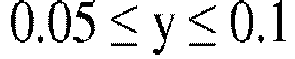
- The thermoelectric conversion material according to Claim 1,
wherein in the chemical formula, the following expressions are satisfied,

- A thermoelectric conversion element comprising:the thermoelectric conversion material according to Claim 1 or 2; andelectrodes each joined to a first surface of the thermoelectric conversion material and a second surface facing the first surface.
- A thermoelectric conversion module comprising:the thermoelectric conversion element according to Claim 3; andterminals each joined to the electrodes of the thermoelectric conversion element.
Applications Claiming Priority (2)
| Application Number | Priority Date | Filing Date | Title |
|---|---|---|---|
| JP2020057017 | 2020-03-27 | ||
| PCT/JP2021/011715 WO2021193534A1 (en) | 2020-03-27 | 2021-03-22 | Thermoelectric conversion material, thermoelectric conversion element, and thermoelectric conversion module |
Publications (1)
| Publication Number | Publication Date |
|---|---|
| EP4129896A1 true EP4129896A1 (en) | 2023-02-08 |
Family
ID=77892142
Family Applications (1)
| Application Number | Title | Priority Date | Filing Date |
|---|---|---|---|
| EP21774921.7A Withdrawn EP4129896A1 (en) | 2020-03-27 | 2021-03-22 | Thermoelectric conversion material, thermoelectric conversion element, and thermoelectric conversion module |
Country Status (6)
| Country | Link |
|---|---|
| US (1) | US20230166970A1 (en) |
| EP (1) | EP4129896A1 (en) |
| JP (1) | JPWO2021193534A1 (en) |
| KR (1) | KR20220159366A (en) |
| CN (1) | CN115349181A (en) |
| WO (1) | WO2021193534A1 (en) |
Family Cites Families (12)
| Publication number | Priority date | Publication date | Assignee | Title |
|---|---|---|---|---|
| JPS5473516A (en) | 1977-11-24 | 1979-06-12 | Sony Corp | Waveform shaping circuit for video signal |
| JPS57130771A (en) | 1981-02-02 | 1982-08-13 | Daihen Corp | Pulse arc welding device |
| JPS59141374A (en) | 1983-01-29 | 1984-08-14 | Sansha Electric Mfg Co Ltd | Pulse arc welding machine |
| CN104211024B (en) | 2013-06-04 | 2016-02-10 | 中国科学院上海硅酸盐研究所 | P type reversible transformation high performance thermoelectric material and preparation method thereof |
| EP3026719B1 (en) | 2013-09-09 | 2019-06-26 | LG Chem, Ltd. | Thermoelectric materials and their manufacturing method |
| JP6460352B2 (en) | 2013-09-09 | 2019-01-30 | エルジー・ケム・リミテッド | Thermoelectric material |
| KR20150044794A (en) * | 2013-10-17 | 2015-04-27 | 주식회사 엘지화학 | Thermoelectric materials and their manufacturing method |
| KR101624310B1 (en) * | 2013-10-17 | 2016-05-25 | 주식회사 엘지화학 | Thermoelectric materials and their manufacturing method |
| JP6311121B2 (en) * | 2014-06-25 | 2018-04-18 | パナソニックIpマネジメント株式会社 | Thermoelectric conversion module |
| WO2019171915A1 (en) * | 2018-03-08 | 2019-09-12 | 住友電気工業株式会社 | Thermoelectric material element, power generator, light sensor, and method for manufacturing thermoelectric material element |
| WO2019181142A1 (en) * | 2018-03-20 | 2019-09-26 | 住友電気工業株式会社 | Thermoelectric conversion material, thermoelectric conversion element, thermoelectric conversion module, and light sensor |
| JP6845912B2 (en) | 2019-12-25 | 2021-03-24 | キヤノン株式会社 | Imaging device and its control method |
-
2021
- 2021-03-22 CN CN202180023158.9A patent/CN115349181A/en active Pending
- 2021-03-22 KR KR1020227031825A patent/KR20220159366A/en not_active Withdrawn
- 2021-03-22 JP JP2022510483A patent/JPWO2021193534A1/ja active Pending
- 2021-03-22 US US17/913,234 patent/US20230166970A1/en not_active Abandoned
- 2021-03-22 EP EP21774921.7A patent/EP4129896A1/en not_active Withdrawn
- 2021-03-22 WO PCT/JP2021/011715 patent/WO2021193534A1/en not_active Ceased
Also Published As
| Publication number | Publication date |
|---|---|
| KR20220159366A (en) | 2022-12-02 |
| JPWO2021193534A1 (en) | 2021-09-30 |
| US20230166970A1 (en) | 2023-06-01 |
| CN115349181A (en) | 2022-11-15 |
| WO2021193534A1 (en) | 2021-09-30 |
Similar Documents
| Publication | Publication Date | Title |
|---|---|---|
| EP1523048B1 (en) | Thermoelectric material and thermoelectric module using the thermoelectric material | |
| EP3144986A1 (en) | Thermoelectric conversion element and thermoelectric conversion module | |
| EP2816593A1 (en) | Solder joint structure, power module, heat-sink-attached substrate for power module, method for producing said substrate, and paste for forming solder underlayer | |
| KR20180114892A (en) | A method of manufacturing a magnesium-based thermoelectric conversion material, a method of manufacturing a magnesium-based thermoelectric conversion element, a magnesium-based thermoelectric conversion material, a magnesium-based thermoelectric conversion element, | |
| US9209378B2 (en) | Fabrication of stable electrode/diffusion barrier layers for thermoelectric filled skutterudite devices | |
| KR100341669B1 (en) | Thermoelectric conversion element | |
| EP3432371A1 (en) | Magnesium-based thermoelectric conversion material, magnesium-based thermoelectric conversion element, thermoelectric conversion device, and method for manufacturing magnesium-based thermoelectric conversion material | |
| EP3349262B1 (en) | Metal paste and thermoelectric module | |
| EP3761381A1 (en) | Thermoelectric conversion material, thermoelectric conversion element, thermoelectric conversion module and method for producing thermoelectric conversion material | |
| KR102299167B1 (en) | Magnesium-based thermoelectric conversion material, magnesium-based thermoelectric conversion element, thermoelectric conversion device, manufacturing method of magnesium-based thermoelectric conversion material | |
| KR102170477B1 (en) | Paste composition for thermoelectric device, thermoelectric device and prepareing method using the same | |
| KR102409289B1 (en) | Magnesium-based thermoelectric conversion material, magnesium-based thermoelectric conversion element, and manufacturing method of magnesium-based thermoelectric conversion material | |
| EP3758080A1 (en) | Thermoelectric conversion material, thermoelectric conversion element, and thermoelectric conversion module | |
| US20230166970A1 (en) | Thermoelectric conversion material, thermoelectric conversion element, and thermoelectric conversion module | |
| EP3767689A1 (en) | Thermoelectric conversion element | |
| EP4036181B1 (en) | Copper oxide paste and method for producing electronic parts | |
| KR102441314B1 (en) | Current sensing resistors and circuit boards | |
| JP3526563B2 (en) | Thermoelectric element, method of manufacturing the same, and thermoelectric module | |
| US9761779B2 (en) | Thermoelectric conversion material | |
| US11223003B2 (en) | Thermoelectric conversion element and method of manufacturing thermoelectric conversion element | |
| US20230097435A1 (en) | Thermoelectric conversion material, thermoelectric conversion element, and thermoelectric conversion module | |
| JPWO2018135286A1 (en) | p-type thermoelectric conversion material, thermoelectric conversion module and method for producing p-type thermoelectric conversion material | |
| US20230043063A1 (en) | Thermoelectric conversion material, thermoelectric conversion element, and thermoelectric conversion module | |
| WO2019168029A1 (en) | Thermoelectric conversion material, thermoelectric conversion element, thermoelectric conversion module and method for producing thermoelectric conversion material | |
| EP4290594A1 (en) | Thermoelectric conversion module, and method for producing thermoelectric conversion module |
Legal Events
| Date | Code | Title | Description |
|---|---|---|---|
| STAA | Information on the status of an ep patent application or granted ep patent |
Free format text: STATUS: THE INTERNATIONAL PUBLICATION HAS BEEN MADE |
|
| PUAI | Public reference made under article 153(3) epc to a published international application that has entered the european phase |
Free format text: ORIGINAL CODE: 0009012 |
|
| STAA | Information on the status of an ep patent application or granted ep patent |
Free format text: STATUS: REQUEST FOR EXAMINATION WAS MADE |
|
| 17P | Request for examination filed |
Effective date: 20220922 |
|
| AK | Designated contracting states |
Kind code of ref document: A1 Designated state(s): AL AT BE BG CH CY CZ DE DK EE ES FI FR GB GR HR HU IE IS IT LI LT LU LV MC MK MT NL NO PL PT RO RS SE SI SK SM TR |
|
| STAA | Information on the status of an ep patent application or granted ep patent |
Free format text: STATUS: THE APPLICATION HAS BEEN WITHDRAWN |
|
| DAV | Request for validation of the european patent (deleted) | ||
| DAX | Request for extension of the european patent (deleted) | ||
| 18W | Application withdrawn |
Effective date: 20230607 |