EP4129746A1 - Virtuelles manuelles getriebesystem für ein elektrisches fahrzeug - Google Patents
Virtuelles manuelles getriebesystem für ein elektrisches fahrzeug Download PDFInfo
- Publication number
- EP4129746A1 EP4129746A1 EP22188780.5A EP22188780A EP4129746A1 EP 4129746 A1 EP4129746 A1 EP 4129746A1 EP 22188780 A EP22188780 A EP 22188780A EP 4129746 A1 EP4129746 A1 EP 4129746A1
- Authority
- EP
- European Patent Office
- Prior art keywords
- torque
- vehicle
- electric motor
- motor
- electric
- Prior art date
- Legal status (The legal status is an assumption and is not a legal conclusion. Google has not performed a legal analysis and makes no representation as to the accuracy of the status listed.)
- Pending
Links
Images


Classifications
-
- B—PERFORMING OPERATIONS; TRANSPORTING
- B60—VEHICLES IN GENERAL
- B60L—PROPULSION OF ELECTRICALLY-PROPELLED VEHICLES; SUPPLYING ELECTRIC POWER FOR AUXILIARY EQUIPMENT OF ELECTRICALLY-PROPELLED VEHICLES; ELECTRODYNAMIC BRAKE SYSTEMS FOR VEHICLES IN GENERAL; MAGNETIC SUSPENSION OR LEVITATION FOR VEHICLES; MONITORING OPERATING VARIABLES OF ELECTRICALLY-PROPELLED VEHICLES; ELECTRIC SAFETY DEVICES FOR ELECTRICALLY-PROPELLED VEHICLES
- B60L15/00—Methods, circuits, or devices for controlling the traction-motor speed of electrically-propelled vehicles
- B60L15/20—Methods, circuits, or devices for controlling the traction-motor speed of electrically-propelled vehicles for control of the vehicle or its driving motor to achieve a desired performance, e.g. speed, torque, programmed variation of speed
-
- G—PHYSICS
- G09—EDUCATION; CRYPTOGRAPHY; DISPLAY; ADVERTISING; SEALS
- G09B—EDUCATIONAL OR DEMONSTRATION APPLIANCES; APPLIANCES FOR TEACHING, OR COMMUNICATING WITH, THE BLIND, DEAF OR MUTE; MODELS; PLANETARIA; GLOBES; MAPS; DIAGRAMS
- G09B9/00—Simulators for teaching or training purposes
- G09B9/02—Simulators for teaching or training purposes for teaching control of vehicles or other craft
- G09B9/04—Simulators for teaching or training purposes for teaching control of vehicles or other craft for teaching control of land vehicles
-
- B—PERFORMING OPERATIONS; TRANSPORTING
- B60—VEHICLES IN GENERAL
- B60L—PROPULSION OF ELECTRICALLY-PROPELLED VEHICLES; SUPPLYING ELECTRIC POWER FOR AUXILIARY EQUIPMENT OF ELECTRICALLY-PROPELLED VEHICLES; ELECTRODYNAMIC BRAKE SYSTEMS FOR VEHICLES IN GENERAL; MAGNETIC SUSPENSION OR LEVITATION FOR VEHICLES; MONITORING OPERATING VARIABLES OF ELECTRICALLY-PROPELLED VEHICLES; ELECTRIC SAFETY DEVICES FOR ELECTRICALLY-PROPELLED VEHICLES
- B60L15/00—Methods, circuits, or devices for controlling the traction-motor speed of electrically-propelled vehicles
- B60L15/20—Methods, circuits, or devices for controlling the traction-motor speed of electrically-propelled vehicles for control of the vehicle or its driving motor to achieve a desired performance, e.g. speed, torque, programmed variation of speed
- B60L15/2054—Methods, circuits, or devices for controlling the traction-motor speed of electrically-propelled vehicles for control of the vehicle or its driving motor to achieve a desired performance, e.g. speed, torque, programmed variation of speed by controlling transmissions or clutches
-
- B—PERFORMING OPERATIONS; TRANSPORTING
- B60—VEHICLES IN GENERAL
- B60L—PROPULSION OF ELECTRICALLY-PROPELLED VEHICLES; SUPPLYING ELECTRIC POWER FOR AUXILIARY EQUIPMENT OF ELECTRICALLY-PROPELLED VEHICLES; ELECTRODYNAMIC BRAKE SYSTEMS FOR VEHICLES IN GENERAL; MAGNETIC SUSPENSION OR LEVITATION FOR VEHICLES; MONITORING OPERATING VARIABLES OF ELECTRICALLY-PROPELLED VEHICLES; ELECTRIC SAFETY DEVICES FOR ELECTRICALLY-PROPELLED VEHICLES
- B60L3/00—Electric devices on electrically-propelled vehicles for safety purposes; Monitoring operating variables, e.g. speed, deceleration or energy consumption
- B60L3/0023—Detecting, eliminating, remedying or compensating for drive train abnormalities, e.g. failures within the drive train
- B60L3/0046—Detecting, eliminating, remedying or compensating for drive train abnormalities, e.g. failures within the drive train relating to electric energy storage systems, e.g. batteries or capacitors
-
- B—PERFORMING OPERATIONS; TRANSPORTING
- B60—VEHICLES IN GENERAL
- B60L—PROPULSION OF ELECTRICALLY-PROPELLED VEHICLES; SUPPLYING ELECTRIC POWER FOR AUXILIARY EQUIPMENT OF ELECTRICALLY-PROPELLED VEHICLES; ELECTRODYNAMIC BRAKE SYSTEMS FOR VEHICLES IN GENERAL; MAGNETIC SUSPENSION OR LEVITATION FOR VEHICLES; MONITORING OPERATING VARIABLES OF ELECTRICALLY-PROPELLED VEHICLES; ELECTRIC SAFETY DEVICES FOR ELECTRICALLY-PROPELLED VEHICLES
- B60L3/00—Electric devices on electrically-propelled vehicles for safety purposes; Monitoring operating variables, e.g. speed, deceleration or energy consumption
- B60L3/0023—Detecting, eliminating, remedying or compensating for drive train abnormalities, e.g. failures within the drive train
- B60L3/0061—Detecting, eliminating, remedying or compensating for drive train abnormalities, e.g. failures within the drive train relating to electrical machines
-
- B—PERFORMING OPERATIONS; TRANSPORTING
- B60—VEHICLES IN GENERAL
- B60L—PROPULSION OF ELECTRICALLY-PROPELLED VEHICLES; SUPPLYING ELECTRIC POWER FOR AUXILIARY EQUIPMENT OF ELECTRICALLY-PROPELLED VEHICLES; ELECTRODYNAMIC BRAKE SYSTEMS FOR VEHICLES IN GENERAL; MAGNETIC SUSPENSION OR LEVITATION FOR VEHICLES; MONITORING OPERATING VARIABLES OF ELECTRICALLY-PROPELLED VEHICLES; ELECTRIC SAFETY DEVICES FOR ELECTRICALLY-PROPELLED VEHICLES
- B60L3/00—Electric devices on electrically-propelled vehicles for safety purposes; Monitoring operating variables, e.g. speed, deceleration or energy consumption
- B60L3/04—Cutting off the power supply under fault conditions
-
- B—PERFORMING OPERATIONS; TRANSPORTING
- B60—VEHICLES IN GENERAL
- B60L—PROPULSION OF ELECTRICALLY-PROPELLED VEHICLES; SUPPLYING ELECTRIC POWER FOR AUXILIARY EQUIPMENT OF ELECTRICALLY-PROPELLED VEHICLES; ELECTRODYNAMIC BRAKE SYSTEMS FOR VEHICLES IN GENERAL; MAGNETIC SUSPENSION OR LEVITATION FOR VEHICLES; MONITORING OPERATING VARIABLES OF ELECTRICALLY-PROPELLED VEHICLES; ELECTRIC SAFETY DEVICES FOR ELECTRICALLY-PROPELLED VEHICLES
- B60L3/00—Electric devices on electrically-propelled vehicles for safety purposes; Monitoring operating variables, e.g. speed, deceleration or energy consumption
- B60L3/06—Limiting the traction current under mechanical overload conditions
-
- B—PERFORMING OPERATIONS; TRANSPORTING
- B60—VEHICLES IN GENERAL
- B60L—PROPULSION OF ELECTRICALLY-PROPELLED VEHICLES; SUPPLYING ELECTRIC POWER FOR AUXILIARY EQUIPMENT OF ELECTRICALLY-PROPELLED VEHICLES; ELECTRODYNAMIC BRAKE SYSTEMS FOR VEHICLES IN GENERAL; MAGNETIC SUSPENSION OR LEVITATION FOR VEHICLES; MONITORING OPERATING VARIABLES OF ELECTRICALLY-PROPELLED VEHICLES; ELECTRIC SAFETY DEVICES FOR ELECTRICALLY-PROPELLED VEHICLES
- B60L50/00—Electric propulsion with power supplied within the vehicle
- B60L50/50—Electric propulsion with power supplied within the vehicle using propulsion power supplied by batteries or fuel cells
- B60L50/51—Electric propulsion with power supplied within the vehicle using propulsion power supplied by batteries or fuel cells characterised by AC-motors
-
- B—PERFORMING OPERATIONS; TRANSPORTING
- B60—VEHICLES IN GENERAL
- B60W—CONJOINT CONTROL OF VEHICLE SUB-UNITS OF DIFFERENT TYPE OR DIFFERENT FUNCTION; CONTROL SYSTEMS SPECIALLY ADAPTED FOR HYBRID VEHICLES; ROAD VEHICLE DRIVE CONTROL SYSTEMS FOR PURPOSES NOT RELATED TO THE CONTROL OF A PARTICULAR SUB-UNIT
- B60W30/00—Purposes of road vehicle drive control systems not related to the control of a particular sub-unit, e.g. of systems using conjoint control of vehicle sub-units
- B60W30/18—Propelling the vehicle
- B60W30/182—Selecting between different operative modes, e.g. comfort and performance modes
-
- F—MECHANICAL ENGINEERING; LIGHTING; HEATING; WEAPONS; BLASTING
- F16—ENGINEERING ELEMENTS AND UNITS; GENERAL MEASURES FOR PRODUCING AND MAINTAINING EFFECTIVE FUNCTIONING OF MACHINES OR INSTALLATIONS; THERMAL INSULATION IN GENERAL
- F16H—GEARING
- F16H59/00—Control inputs to control units of change-speed- or reversing-gearings for conveying rotary motion
- F16H59/02—Selector apparatus
-
- F—MECHANICAL ENGINEERING; LIGHTING; HEATING; WEAPONS; BLASTING
- F16—ENGINEERING ELEMENTS AND UNITS; GENERAL MEASURES FOR PRODUCING AND MAINTAINING EFFECTIVE FUNCTIONING OF MACHINES OR INSTALLATIONS; THERMAL INSULATION IN GENERAL
- F16H—GEARING
- F16H61/00—Control functions within control units of change-speed- or reversing-gearings for conveying rotary motion ; Control of exclusively fluid gearing, friction gearing, gearings with endless flexible members or other particular types of gearing
- F16H61/02—Control functions within control units of change-speed- or reversing-gearings for conveying rotary motion ; Control of exclusively fluid gearing, friction gearing, gearings with endless flexible members or other particular types of gearing characterised by the signals used
- F16H61/0202—Control functions within control units of change-speed- or reversing-gearings for conveying rotary motion ; Control of exclusively fluid gearing, friction gearing, gearings with endless flexible members or other particular types of gearing characterised by the signals used the signals being electric
- F16H61/0204—Control functions within control units of change-speed- or reversing-gearings for conveying rotary motion ; Control of exclusively fluid gearing, friction gearing, gearings with endless flexible members or other particular types of gearing characterised by the signals used the signals being electric for gearshift control, e.g. control functions for performing shifting or generation of shift signal
- F16H61/0213—Control functions within control units of change-speed- or reversing-gearings for conveying rotary motion ; Control of exclusively fluid gearing, friction gearing, gearings with endless flexible members or other particular types of gearing characterised by the signals used the signals being electric for gearshift control, e.g. control functions for performing shifting or generation of shift signal characterised by the method for generating shift signals
-
- G—PHYSICS
- G09—EDUCATION; CRYPTOGRAPHY; DISPLAY; ADVERTISING; SEALS
- G09B—EDUCATIONAL OR DEMONSTRATION APPLIANCES; APPLIANCES FOR TEACHING, OR COMMUNICATING WITH, THE BLIND, DEAF OR MUTE; MODELS; PLANETARIA; GLOBES; MAPS; DIAGRAMS
- G09B25/00—Models for purposes not provided for in G09B23/00, e.g. full-sized devices for demonstration purposes
-
- B—PERFORMING OPERATIONS; TRANSPORTING
- B60—VEHICLES IN GENERAL
- B60L—PROPULSION OF ELECTRICALLY-PROPELLED VEHICLES; SUPPLYING ELECTRIC POWER FOR AUXILIARY EQUIPMENT OF ELECTRICALLY-PROPELLED VEHICLES; ELECTRODYNAMIC BRAKE SYSTEMS FOR VEHICLES IN GENERAL; MAGNETIC SUSPENSION OR LEVITATION FOR VEHICLES; MONITORING OPERATING VARIABLES OF ELECTRICALLY-PROPELLED VEHICLES; ELECTRIC SAFETY DEVICES FOR ELECTRICALLY-PROPELLED VEHICLES
- B60L2240/00—Control parameters of input or output; Target parameters
- B60L2240/10—Vehicle control parameters
- B60L2240/12—Speed
-
- B—PERFORMING OPERATIONS; TRANSPORTING
- B60—VEHICLES IN GENERAL
- B60L—PROPULSION OF ELECTRICALLY-PROPELLED VEHICLES; SUPPLYING ELECTRIC POWER FOR AUXILIARY EQUIPMENT OF ELECTRICALLY-PROPELLED VEHICLES; ELECTRODYNAMIC BRAKE SYSTEMS FOR VEHICLES IN GENERAL; MAGNETIC SUSPENSION OR LEVITATION FOR VEHICLES; MONITORING OPERATING VARIABLES OF ELECTRICALLY-PROPELLED VEHICLES; ELECTRIC SAFETY DEVICES FOR ELECTRICALLY-PROPELLED VEHICLES
- B60L2240/00—Control parameters of input or output; Target parameters
- B60L2240/40—Drive Train control parameters
- B60L2240/42—Drive Train control parameters related to electric machines
- B60L2240/421—Speed
-
- B—PERFORMING OPERATIONS; TRANSPORTING
- B60—VEHICLES IN GENERAL
- B60L—PROPULSION OF ELECTRICALLY-PROPELLED VEHICLES; SUPPLYING ELECTRIC POWER FOR AUXILIARY EQUIPMENT OF ELECTRICALLY-PROPELLED VEHICLES; ELECTRODYNAMIC BRAKE SYSTEMS FOR VEHICLES IN GENERAL; MAGNETIC SUSPENSION OR LEVITATION FOR VEHICLES; MONITORING OPERATING VARIABLES OF ELECTRICALLY-PROPELLED VEHICLES; ELECTRIC SAFETY DEVICES FOR ELECTRICALLY-PROPELLED VEHICLES
- B60L2240/00—Control parameters of input or output; Target parameters
- B60L2240/40—Drive Train control parameters
- B60L2240/42—Drive Train control parameters related to electric machines
- B60L2240/423—Torque
-
- B—PERFORMING OPERATIONS; TRANSPORTING
- B60—VEHICLES IN GENERAL
- B60L—PROPULSION OF ELECTRICALLY-PROPELLED VEHICLES; SUPPLYING ELECTRIC POWER FOR AUXILIARY EQUIPMENT OF ELECTRICALLY-PROPELLED VEHICLES; ELECTRODYNAMIC BRAKE SYSTEMS FOR VEHICLES IN GENERAL; MAGNETIC SUSPENSION OR LEVITATION FOR VEHICLES; MONITORING OPERATING VARIABLES OF ELECTRICALLY-PROPELLED VEHICLES; ELECTRIC SAFETY DEVICES FOR ELECTRICALLY-PROPELLED VEHICLES
- B60L2240/00—Control parameters of input or output; Target parameters
- B60L2240/40—Drive Train control parameters
- B60L2240/48—Drive Train control parameters related to transmissions
- B60L2240/486—Operating parameters
-
- B—PERFORMING OPERATIONS; TRANSPORTING
- B60—VEHICLES IN GENERAL
- B60L—PROPULSION OF ELECTRICALLY-PROPELLED VEHICLES; SUPPLYING ELECTRIC POWER FOR AUXILIARY EQUIPMENT OF ELECTRICALLY-PROPELLED VEHICLES; ELECTRODYNAMIC BRAKE SYSTEMS FOR VEHICLES IN GENERAL; MAGNETIC SUSPENSION OR LEVITATION FOR VEHICLES; MONITORING OPERATING VARIABLES OF ELECTRICALLY-PROPELLED VEHICLES; ELECTRIC SAFETY DEVICES FOR ELECTRICALLY-PROPELLED VEHICLES
- B60L2240/00—Control parameters of input or output; Target parameters
- B60L2240/40—Drive Train control parameters
- B60L2240/54—Drive Train control parameters related to batteries
- B60L2240/545—Temperature
-
- B—PERFORMING OPERATIONS; TRANSPORTING
- B60—VEHICLES IN GENERAL
- B60L—PROPULSION OF ELECTRICALLY-PROPELLED VEHICLES; SUPPLYING ELECTRIC POWER FOR AUXILIARY EQUIPMENT OF ELECTRICALLY-PROPELLED VEHICLES; ELECTRODYNAMIC BRAKE SYSTEMS FOR VEHICLES IN GENERAL; MAGNETIC SUSPENSION OR LEVITATION FOR VEHICLES; MONITORING OPERATING VARIABLES OF ELECTRICALLY-PROPELLED VEHICLES; ELECTRIC SAFETY DEVICES FOR ELECTRICALLY-PROPELLED VEHICLES
- B60L2240/00—Control parameters of input or output; Target parameters
- B60L2240/80—Time limits
-
- B—PERFORMING OPERATIONS; TRANSPORTING
- B60—VEHICLES IN GENERAL
- B60L—PROPULSION OF ELECTRICALLY-PROPELLED VEHICLES; SUPPLYING ELECTRIC POWER FOR AUXILIARY EQUIPMENT OF ELECTRICALLY-PROPELLED VEHICLES; ELECTRODYNAMIC BRAKE SYSTEMS FOR VEHICLES IN GENERAL; MAGNETIC SUSPENSION OR LEVITATION FOR VEHICLES; MONITORING OPERATING VARIABLES OF ELECTRICALLY-PROPELLED VEHICLES; ELECTRIC SAFETY DEVICES FOR ELECTRICALLY-PROPELLED VEHICLES
- B60L2250/00—Driver interactions
- B60L2250/24—Driver interactions by lever actuation
-
- B—PERFORMING OPERATIONS; TRANSPORTING
- B60—VEHICLES IN GENERAL
- B60L—PROPULSION OF ELECTRICALLY-PROPELLED VEHICLES; SUPPLYING ELECTRIC POWER FOR AUXILIARY EQUIPMENT OF ELECTRICALLY-PROPELLED VEHICLES; ELECTRODYNAMIC BRAKE SYSTEMS FOR VEHICLES IN GENERAL; MAGNETIC SUSPENSION OR LEVITATION FOR VEHICLES; MONITORING OPERATING VARIABLES OF ELECTRICALLY-PROPELLED VEHICLES; ELECTRIC SAFETY DEVICES FOR ELECTRICALLY-PROPELLED VEHICLES
- B60L2250/00—Driver interactions
- B60L2250/26—Driver interactions by pedal actuation
-
- B—PERFORMING OPERATIONS; TRANSPORTING
- B60—VEHICLES IN GENERAL
- B60L—PROPULSION OF ELECTRICALLY-PROPELLED VEHICLES; SUPPLYING ELECTRIC POWER FOR AUXILIARY EQUIPMENT OF ELECTRICALLY-PROPELLED VEHICLES; ELECTRODYNAMIC BRAKE SYSTEMS FOR VEHICLES IN GENERAL; MAGNETIC SUSPENSION OR LEVITATION FOR VEHICLES; MONITORING OPERATING VARIABLES OF ELECTRICALLY-PROPELLED VEHICLES; ELECTRIC SAFETY DEVICES FOR ELECTRICALLY-PROPELLED VEHICLES
- B60L2260/00—Operating Modes
- B60L2260/20—Drive modes; Transition between modes
- B60L2260/24—Coasting mode
-
- B—PERFORMING OPERATIONS; TRANSPORTING
- B60—VEHICLES IN GENERAL
- B60L—PROPULSION OF ELECTRICALLY-PROPELLED VEHICLES; SUPPLYING ELECTRIC POWER FOR AUXILIARY EQUIPMENT OF ELECTRICALLY-PROPELLED VEHICLES; ELECTRODYNAMIC BRAKE SYSTEMS FOR VEHICLES IN GENERAL; MAGNETIC SUSPENSION OR LEVITATION FOR VEHICLES; MONITORING OPERATING VARIABLES OF ELECTRICALLY-PROPELLED VEHICLES; ELECTRIC SAFETY DEVICES FOR ELECTRICALLY-PROPELLED VEHICLES
- B60L2260/00—Operating Modes
- B60L2260/20—Drive modes; Transition between modes
- B60L2260/30—Engine braking emulation
-
- B—PERFORMING OPERATIONS; TRANSPORTING
- B60—VEHICLES IN GENERAL
- B60L—PROPULSION OF ELECTRICALLY-PROPELLED VEHICLES; SUPPLYING ELECTRIC POWER FOR AUXILIARY EQUIPMENT OF ELECTRICALLY-PROPELLED VEHICLES; ELECTRODYNAMIC BRAKE SYSTEMS FOR VEHICLES IN GENERAL; MAGNETIC SUSPENSION OR LEVITATION FOR VEHICLES; MONITORING OPERATING VARIABLES OF ELECTRICALLY-PROPELLED VEHICLES; ELECTRIC SAFETY DEVICES FOR ELECTRICALLY-PROPELLED VEHICLES
- B60L2260/00—Operating Modes
- B60L2260/40—Control modes
- B60L2260/44—Control modes by parameter estimation
-
- B—PERFORMING OPERATIONS; TRANSPORTING
- B60—VEHICLES IN GENERAL
- B60L—PROPULSION OF ELECTRICALLY-PROPELLED VEHICLES; SUPPLYING ELECTRIC POWER FOR AUXILIARY EQUIPMENT OF ELECTRICALLY-PROPELLED VEHICLES; ELECTRODYNAMIC BRAKE SYSTEMS FOR VEHICLES IN GENERAL; MAGNETIC SUSPENSION OR LEVITATION FOR VEHICLES; MONITORING OPERATING VARIABLES OF ELECTRICALLY-PROPELLED VEHICLES; ELECTRIC SAFETY DEVICES FOR ELECTRICALLY-PROPELLED VEHICLES
- B60L2270/00—Problem solutions or means not otherwise provided for
- B60L2270/10—Emission reduction
- B60L2270/14—Emission reduction of noise
- B60L2270/145—Structure borne vibrations
-
- F—MECHANICAL ENGINEERING; LIGHTING; HEATING; WEAPONS; BLASTING
- F16—ENGINEERING ELEMENTS AND UNITS; GENERAL MEASURES FOR PRODUCING AND MAINTAINING EFFECTIVE FUNCTIONING OF MACHINES OR INSTALLATIONS; THERMAL INSULATION IN GENERAL
- F16H—GEARING
- F16H59/00—Control inputs to control units of change-speed- or reversing-gearings for conveying rotary motion
- F16H59/02—Selector apparatus
- F16H2059/0221—Selector apparatus for selecting modes, e.g. sport, normal, economy
-
- Y—GENERAL TAGGING OF NEW TECHNOLOGICAL DEVELOPMENTS; GENERAL TAGGING OF CROSS-SECTIONAL TECHNOLOGIES SPANNING OVER SEVERAL SECTIONS OF THE IPC; TECHNICAL SUBJECTS COVERED BY FORMER USPC CROSS-REFERENCE ART COLLECTIONS [XRACs] AND DIGESTS
- Y02—TECHNOLOGIES OR APPLICATIONS FOR MITIGATION OR ADAPTATION AGAINST CLIMATE CHANGE
- Y02T—CLIMATE CHANGE MITIGATION TECHNOLOGIES RELATED TO TRANSPORTATION
- Y02T10/00—Road transport of goods or passengers
- Y02T10/60—Other road transportation technologies with climate change mitigation effect
- Y02T10/62—Hybrid vehicles
-
- Y—GENERAL TAGGING OF NEW TECHNOLOGICAL DEVELOPMENTS; GENERAL TAGGING OF CROSS-SECTIONAL TECHNOLOGIES SPANNING OVER SEVERAL SECTIONS OF THE IPC; TECHNICAL SUBJECTS COVERED BY FORMER USPC CROSS-REFERENCE ART COLLECTIONS [XRACs] AND DIGESTS
- Y02—TECHNOLOGIES OR APPLICATIONS FOR MITIGATION OR ADAPTATION AGAINST CLIMATE CHANGE
- Y02T—CLIMATE CHANGE MITIGATION TECHNOLOGIES RELATED TO TRANSPORTATION
- Y02T10/00—Road transport of goods or passengers
- Y02T10/60—Other road transportation technologies with climate change mitigation effect
- Y02T10/72—Electric energy management in electromobility
Definitions
- Embodiments of the present invention relate to the art of a control system for an electric vehicle configured to simulate behavior of conventional vehicles having manual transmissions.
- JP-B2-6787507 describes one example of an electric vehicle having the above-mentioned function.
- the electric vehicle described in JP-B2-6787507 comprises a shift device that is operated by a driver to select a mode from a plurality of modes in which torque characteristics of an electric motor differ stepwise, and a clutch device that simulates an operation of a conventional clutch mechanism for selectively transmitting torque between a prime mover and drive wheels.
- torque of the electric motor is controlled based on a signal including the mode selected by the shift device and a signal including an operation amount of the clutch device.
- the torque transmitted from the motor to the drive wheels is reduced in accordance with an increase in an operating amount of the clutch device corresponding to a depression of the conventional clutch pedal, and increased in accordance with a reduction in an operating amount of the clutch device and the selected mode.
- a control device described in JP-A-2011-20542 is configured to control a change rate of a motor torque. Specifically, in a case of increasing a transmission torque when a friction element engaged partially while slipping is engaged completely, the control device described in JP-A-2011-20542 controls a change rate of a torque of a motor serving as a prime mover based on a change in the transmission torque and a requested driving torque.
- the motor as a prime mover generates a driving torque when serving as a motor, and generates a braking torque when regenerating energy. Because of such versatility of an output torque of the motor, as described in JP-B2-6787507 , it is possible to simulate the behavior of the conventional vehicle having a manual transmission by the electric vehicle.
- the motor is connected to an electric storage device including a secondary battery so that electricity is supplied repeatedly from the electric storage device to the motor and the electric storage device is charged repeatedly so as to simulate the behavior of the vehicle having the manual transmission.
- the electric storage device will be heated and properties of electrolyte will be changed thereby damaging the electric storage device.
- charge and discharge of the electric storage device is restricted to protect the electric storage device.
- a manual shifting operation is executed to change the behavior (or a driving torque) of the vehicle in line with the driver's intention. To this end, it is preferable to execute the manual shifting operation promptly, and to change the driving torque and the braking torque promptly in response to the manual shifting operation.
- charge and discharge of the electric storage device is restricted to protect the electric storage device.
- the electric vehicle simulates the behavior of the vehicle having the manual transmission
- a required amount of electricity may not be discharged from the electric storage device, and the electric storage device may not be charged with a required amount of electricity.
- the electric vehicle may not simulate the behavior of the vehicle having the manual transmission intended by the driver.
- it is required to allow the electric vehicle to simulate or imitate the behavior of the conventional vehicle having the manual transmission while protecting the electric storage device by restricting charge and discharge of the electric storage device.
- a virtual manual transmission system for an electric vehicle comprising: an electric motor that serves as a prime mover; an accelerator device that is operated by a driver to control an output torque of the electric motor; an electric storage device that is connected to the electric motor; a clutch device that is operated by the driver to transmit a torque between the electric motor and a pair of drive wheels, and to interrupt torque transmission between the electric motor and the drive wheels; and a shifting device that is operated by the driver to select a mode determining a relation between the output torque of the electric motor and a driving torque delivered to the drive wheels.
- at least one of a change rate of the output torque of the electric motor and an input/output power to/from the electric storage device may be regulated.
- the virtual manual transmission system is provided with a controller that controls the output torque of the electric motor.
- the controller is configured to: change the output torque of the electric motor based on a detection signal representing an execution of a virtual manual shifting including an operation of the clutch device to allow or interrupt the torque transmission between the electric motor and the drive wheels, an operation of the accelerator device to change the output torque of the electric motor executed in connection with the operation of the clutch device, and an operation of the shifting device to select the mode; and change an upper limit value of the at least one of the change rate of the output torque of the electric motor and the input/output power to/from the electric storage device, so as to reduce a regulation on the change rate of the output torque of the electric motor or the input/output power to/from the electric storage device.
- the controller may be further configured to reduce the regulation when the clutch device is operated to interrupt torque transmission between the electric motor and the drive wheels, or to allow torque transmission between the electric motor and the drive wheels.
- the controller may be further configured to reduce the regulation for a predetermined period of time after completion of the operation of the clutch device to interrupt torque transmission between the electric motor and the drive wheels, or to allow torque transmission between the electric motor and the drive wheels.
- a numerical model of a model vehicle having a transmission in which a speed ratio is changed by operating a shifting device and an engine connected to the transmission may be stored in the controller.
- the controller may be further configured to: calculate a virtual engine speed based on an expected speed ratio of the transmission of the model vehicle and a rotational speed of a predetermined rotary member corresponding to a speed of the electric vehicle; and reduce the regulation when the virtual engine speed is equal to a reference speed or higher.
- the controller may be further configured to: determine a satisfaction of a condition to protect the electric motor or the electric storage device; and restrict reduction of the regulation upon satisfaction of the condition to protect the electric motor or the electric storage device.
- the controller may be further configured to change the upper limit value to reduce the regulation on a preferential basis in a case of operating the clutch device to interrupt torque transmission between the electric motor and the drive wheels, compared to a case of operating the clutch device to allow torque transmission between the electric motor and the drive wheels.
- the output torque of the motor is controlled to imitate the behavior of the model vehicle during execution of the virtual manual shifting in the electric vehicle. If the input/output power to/from the electric storage device exceeds the upper limit value during execution of the virtual manual shifting, the upper limit value of the input/output power is changed to reduce the regulation on the input/output power. According to the exemplary embodiment of the present invention, therefore, the motor is allowed to change the output torque thereof sufficiently to imitate the behavior of the model vehicle during execution of the virtual manual shifting.
- the clutch device and the shifting device are operated only for a short period of time during execution of the virtual manual shifting, and the regulation on the input/output power to/from the electric storage device is reduced only during execution of the virtual manual shifting.
- the load on the electric storage device is not especially increased, and hence the electric storage device will not be damaged.
- the electric vehicle is allowed to imitate the behavior of the model vehicle during execution of the virtual manual shifting, while protecting the electric storage device.
- the reduction in the regulation on the change rate of the output torque of the motor or the input/output power to/from the electric storage device is restricted strongly in a case of operating the clutch device to allow torque transmission between the electric motor and the drive wheels, compared to a case of operating the clutch device to interrupt torque transmission between the electric motor and the drive wheels.
- the regulation on the change rate of the output torque of the motor or the input/output power to/from the electric storage device is reduced on a preferential basis in the case of operating the clutch device to interrupt torque transmission between the electric motor and the drive wheels, compared to the case of operating the clutch device to allow torque transmission between the electric motor and the drive wheels.
- the electric vehicle may be prevented from moving unintentionally while the torque transmission between the electric motor and the drive wheels is interrupted. For this reason, the electric vehicle is allowed to imitate the behavior of the model vehicle during execution of the virtual manual shifting precisely as intended by the driver.
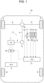
- a vehicle Ve an electric vehicle (hereinafter simply called a vehicle) Ve to which the virtual manual transmission system according to the embodiment of the present invention is applied.
- the vehicle Ve shown in Fig. 1 is a front drive layout electric vehicle propelled by delivering an output torque of a motor (referred to as "MG" in Fig. 1 ) 1 as a prime mover to a pair of front wheels 2.
- MG motor
- a motor/generator that serves not only as a motor but also as a generator is adopted as the motor 1.
- the motor 1 serves as a motor to generate a driving torque to propel the vehicle Ve by supplying electric power to the motor 1 from an electric storage device (referred to as "BATT" in Fig. 1 ) 3.
- the motor 1 also serves as a generator to generate electric power when rotated passively by a torque delivered thereto.
- a synchronous motor and an induction motor may be adopted as the motor 1.
- An output shaft 4 of the motor 1 is connected to one end of a propeller shaft 6 through a gear unit 5, and the other end of the propeller shaft 6 is connected to a differential gear unit 7. That is, the output torque of the motor 1 is distributed to right and left driveshafts 8 through the differential gear unit 7, and further distributed to the front wheels 2 through the driveshafts 8.
- the virtual manual transmission system according to the exemplary embodiment of the present invention may also be applied to a rear-drive layout electric vehicle in which the output torque of the motor 1 is delivered to a pair of rear wheels 9, or a four-wheel-drive layout electric vehicle in which the output torque of the motor 1 is distributed to the front wheels 2 and the rear wheels 9 through a transfer.
- the motor 1 is provided with an inverter (referred to as "INV” in Fig. 1 ) 10 so that a magnitude and a frequency of electric current supplied to each phase of the motor 1 are controlled by the inverter 10, and the inverter 10 is connected to an electric storage device (referred to as "BATT" in Fig. 1 ) 3 that discharges a direct current.
- an auxiliary such as a converter may be arranged to boost a voltage of electric power supplied from the electric storage device 3.
- the electric storage device 3 may include a secondary battery such as a lithium-ion battery and an electronic component such as a capacitor.
- the vehicle Ve is provided with an electronic control unit (to be abbreviated as the "ECU” hereinafter) 11 as a controller.
- the ECU 11 comprises a microcomputer as its main constituent configured to perform calculation based on incident data from sensors and formulas as well as maps install in advance, and to transmit calculation results in the form of command signals to e.g., the inverter 10.
- the vehicle Ve comprises: an accelerator pedal 12 that is manipulated by a driver to accelerate and decelerate the vehicle Ve by changing an output torque of the motor 1; an accelerator sensor 13 that detects a depression (i.e., a position) of the accelerator pedal 12 and a pedal force applied to the accelerator pedal 12; a brake pedal 14 that is manipulated by the driver to decelerate and stop the vehicle Ve; a brake sensor 15 that detects a depression of the brake pedal 14 and a pedal force applied to the brake pedal 14; and a vehicle speed sensor 16 as a rotational speed sensor that detects a rotational speed of the propeller shaft 6.
- Those sensors 13, 15, and 16 are connected to the ECU 11 so that data collected by the sensors 13, 15, and 16 are sent to the ECU 11 in the form of detection signal.
- an accelerator device comprises the accelerator pedal 12 and the accelerator sensor 13.
- the vehicle Ve is provided with devices for simulating or imitating the behaviors of conventional vehicles having a manual transmission (referred to as "manual transmission vehicle” hereinafter).
- the vehicle Ve is provided with a shifting device 17 including a shift lever and a paddle switch.
- the shifting device 17 is operated to shift a virtual gear stage among a plurality of forward stages, a reverse stage, and a neutral stage.
- a torque transmission between an engine and drive wheels is temporarily interrupted to engage and disengage predetermined gear pairs, and to reduce a shift shock.
- a clutch is disengaged by depressing a clutch pedal and engaged by returning the clutch pedal.
- the vehicle Ve is further provided with: a clutch pedal 18; a shift position sensor 19 that detects a position of the shifting device 17 or a virtual gear stage (or mode) selected by operating the shifting device 17; and a clutch position sensor 20 that detects a depression of the clutch pedal 18.
- Those sensors 19, and 20 are also connected to the ECU 11 so that data collected by the sensors 19, and 20 are also sent to the ECU 11 in the form of detection signal.
- a clutch device comprises the clutch pedal 18 and the clutch position sensor 20.
- An operating mode of the vehicle Ve may be selected from an EV (i.e., electric vehicle) mode and a virtual manual mode.
- EV i.e., electric vehicle
- a virtual manual mode an output torque of the motor 1 is controlled to propel and decelerate the vehicle Ve based on a position of the accelerator pedal 12 representing a drive demand.
- the vehicle Ve is operated while simulating the behavior of the manual transmission vehicle.
- the electric vehicle is allowed to imitate the behavior of the manual transmission vehicle by the procedures described in JP-B2-6787507 . The procedures to imitate the behavior of the manual transmission vehicle will be explained briefly hereinafter.
- specifications of the manual transmission vehicle selected as a model vehicle are numerically modeled and stored in the ECU 11.
- an expected behavior of the model vehicle based on a current running condition of the vehicle Ve is computed by the ECU 11 based on: an actual depression (or position) of the accelerator pedal 12 detected by the accelerator sensor 13; a position of the shifting device 17 detected by shift position sensor 19; an actual depression of the clutch pedal 18 detected by the clutch position sensor 20; and an actual rotational speed of the propeller shaft 6 detected by the vehicle speed sensor 16.
- the ECU 11 calculates a target output torque of the motor 1 (including a driving torque and a braking torque) to actualize the expected behavior of the model vehicle, and controls the inverter 10 to allow the motor 1 to generate the target output torque.
- a virtual engine speed of the model vehicle is calculated based on the data collected by the above-mentioned sensors 13, 19, 20, and 16 on the basis that the model vehicle has a geared transmission connected to an output shaft of an engine.
- the virtual engine speed may be calculated by multiplying the rotational speed of the propeller shaft 6 detected by the vehicle speed sensor 16: by a speed ratio of the virtual gear stage selected by the shifting device 17; and by a slip ratio corresponding to the depression of the clutch pedal 18 detected by the clutch position sensor 20.
- Fig. 2 there are shown functional devices of the ECU 11 to simulate the behavior of the model vehicle. As illustrated in Fig. 2 , in order to calculate the virtual engine speed, the ECU 11 is provided with a virtual engine speed calculator 110.
- a displacement, a relation between a speed and an output torque, an efficiency and so on of the engine of the model vehicle are numerically modeled. Therefore, a virtual engine output torque of the model vehicle may be calculated based on the calculated virtual engine speed and the detected position of the accelerator pedal 12, while with reference to a map determining a relation between a speed and an output torque of the engine of the model vehicle. Specifically, the virtual engine output torque is calculated by a virtual engine output torque calculator 111 of the ECU 11.
- the behavior of the model vehicle is simulated on the basis that a friction clutch in which a torque transmitting capacity varies continuously is employed in the model vehicle.
- a relation between a depression of the clutch pedal 18 and a virtual torque transmitting capacity of the friction clutch of the model vehicle is determined in the form of a map, and such map is stored in the ECU 11.
- the map is prepared in such a manner that a gain of the virtual torque transmitting capacity varies between 0 and 1.
- the gain of the virtual torque transmitting capacity is maintained to 1 as long as the depression of the clutch pedal 18 falls within a range from 0 to a predetermined angle, and reduced linearly or proportionally from 1 with an increase in the depression of the clutch pedal 18 from the predetermined angle.
- a virtual clutch output torque of the model vehicle is governed by the above-mentioned gain, which is calculated based on an actual depression of the clutch pedal 18 detected by the clutch position sensor 20 while with reference to the above-mentioned map.
- the gain of the virtual torque transmitting capacity is calculated by a torque transmitting gain calculator 112 of the ECU 11.
- a manual transmission vehicle having a manual transmission is selected as the model vehicle.
- an output torque of the engine is supposed to be changed in accordance with the above-explained gain of the torque transmitting capacity of the clutch, and the output torque of the engine is supposed to be delivered from the clutch to the manual transmission.
- the output torque of the clutch of the model vehicle may be simulated by multiplying the virtual engine output torque calculated by the virtual engine output torque calculator 111 by the gain calculated by the torque transmitting gain calculator 112.
- the output torque of the clutch of the model vehicle is simulated as a virtual clutch output torque by a virtual clutch output torque calculator 113 of the ECU 11.
- a virtual gear ratio (i.e., a virtual speed ratio) of the manual transmission of the model vehicle is simulated on the basis of current running conditions of the vehicle Ve.
- the virtual gear ratio of the manual transmission is simulated as a ratio between the virtual engine speed and a virtual output speed of the manual transmission (i.e., a rotational speed of a propeller shaft) of the model vehicle. That is, the virtual gear ratio of the manual transmission may be calculated by dividing the virtual engine speed by a rotational speed of the propeller shaft 6 detected by the vehicle speed sensor 16.
- the virtual gear ratio of the manual transmission is calculated by a virtual gear ratio calculator 114 of the ECU 11.
- the virtual output torque of the manual transmission of the model vehicle is calculated by a virtual transmission output torque calculator 115 of the ECU 11.
- the torque delivered to the manual transmission is changed in accordance with the speed ratio of the manual transmission, and further delivered from the manual transmission. Therefore, the virtual output torque of the manual transmission may be calculated by multiplying the virtual clutch output torque supposed to be delivered to the manual transmission by the speed ratio of the manual transmission. As described, the virtual clutch output torque is governed by the gain calculated by the torque transmitting gain calculator 112.
- the virtual clutch output torque is changed in accordance with the virtual torque transmitting capacity being changed to simulate an intermittence of torque transmission through the clutch during manual shifting.
- the ECU 11 controls the inverter 10 in such a manner as to generate the virtual output torque (corresponding to a torque of the propeller shaft 6) calculated by the virtual transmission output torque calculator 115.
- the output torque of the manual transmission is changed significantly by: an interruption of torque transmission due to disengagement of the clutch; a commencement of torque transmission due to engagement of the clutch; and torsional behaviors of the manual transmission and the model vehicle itself due to change in the torque. Therefore, the electric storage device 3 and the inverter 10 of the vehicle Ve will be subjected to heavy loads when changing the torque of the motor 1 in line with such torque change in the model vehicle, and the electric storage device 3 would be damaged due to excessive charging and discharging.
- the ECU 11 comprises a regulator 116 that regulates a discharge of the electric storage device 3 to the motor 1 and a charging of the electric storage device 3 by the electric power generated by the motor 1.
- the regulator 116 is configured to set an upper limit value (or a restriction value) of at least one of: a change rate of an available output torque of the motor 1; and an input/output power to/from the electric storage device 3. That is, the regulator 116 controls the inverter 10 in such a manner that a charging or discharging amount of the electric storage device 3, or a change rate of charging or discharging amount of the electric storage device 3 will not exceed the upper limit value.
- Such upper limit value is set to a value possible to protect the electric storage device 3 taking account of a specification, a condition, a deterioration, an SOC level, a temperature and so on of the electric storage device 3.
- a regulation level to protect the electric storage device 3 may be categorized into: a high level to be selected to prevent the electric storage device 3 from deteriorating earlier than an expected aging deterioration in a normal condition; an intermediate level to be selected to protect the electric storage device 3 from permanent damage without taking into consideration a temporal damage; and a low level to be selected to protect the electric storage device 3 only from critical damage which might cause a malfunction of the electric storage device 3 immediately.
- the above-mentioned upper limit value is set to a smallest value when the high regulation level is selected, to a largest value when the low regulation level is selected, and to an intermediate value when the intermediate regulation level is selected.
- the high regulation level is selected in the normal condition, and the low regulation level or the intermediate regulation level is selected upon satisfaction of a predetermined condition. Specifically, restrictions of the change rate of available output torque of the motor 1 and the input/output power to/from the electric storage device 3 set by the regulator 116 are reduced by a regulation reducer 117 upon satisfaction of a predetermined condition, when controlling the output torque of the motor 1 in line with the virtual output torque.
- Fig. 3 there is shown one example of a routine to change the regulation level while imitating the behavior of the model vehicle.
- the routine shown in Fig. 3 is executed by the ECU 11 in a condition that the shifting device 17 and the clutch pedal 18 are activated during propulsion of the vehicle Ve.
- a virtual engine speed Ne is equal to or higher than a reference speed ⁇ .
- the driver is allowed to execute a virtual manual shifting during propulsion by manipulating the shifting device 17 and the clutch pedal 18, and the output torque of the motor 1 is changed in such a manner as to imitate the behavior of the model vehicle in response to an execution of the virtual manual shifting. Therefore, the reference speed ⁇ is set to determine whether the electric storage device 3 and the inverter 10 are subjected to high loads when controlling the output torque of the motor 1 to simulate the behavior of the model vehicle.
- the virtual engine speed Ne in a case that the virtual engine speed Ne is high, the virtual engine speed Ne will be reduced significantly when the clutch pedal 18 is depressed. In this case, therefore, an input power and an output power to/from the electric storage device 3, and a change rate of the torque of the motor 1 will be increased to imitate the behavior of the model vehicle. That is, a load on the electric storage device 3 will be increased to control the torque of the motor 1.
- Such load on the electric storage device 3 changes depending on a running condition such as a speed of the vehicle Ve, therefore, the reference speed ⁇ may be changed depending on a current running condition of the vehicle Ve.
- step S2 the routine progresses to step S2 to increase the upper limit value of the change rate of the output torque of the motor 1, and thereafter returns.
- a load on the electric storage device 3 during the virtual manual shifting to be executed in the future is expected to be increased compared to that in the normal condition. That is, the load on the electric storage device 3 during the virtual manual shifting to be executed in the future is expected to exceed the upper limit value of the high regulation level set by the regulator 116.
- the upper limit value of the change rate of the output torque of the motor 1 is increased to enable the motor 1 to generate torque in such a manner as to imitate the behavior of the model vehicle during execution of the virtual manual shifting.
- the regulation of the input/output power to/from the electric storage device 3 is reduced to enable the motor 1 to generate torque in such a manner as to imitate the behavior of the model vehicle during execution of the virtual manual shifting.
- the routine returns to step S1 to maintain the high regulation level.
- step S3 it is determined at step S3 whether the clutch pedal 18 is currently being manipulated. In other words, at step S3, it is determined whether a position of the clutch pedal 18 is currently being changed. Specifically, it is determined whether the clutch pedal 18 is currently being depressed to virtually interrupt torque transmission, or currently being returned to virtually start torque transmission. In the model vehicle, if the clutch is disengaged during manual shifting, the torque transmission to the drive wheels will be interrupted immediately. In the vehicle Ve, therefore, it is necessary to change the torque of the motor 1 abruptly to imitate such abrupt reduction of the transmission torque in the model vehicle. Consequently, the input/output power to/from the electric storage device 3 and the change rate of the output torque of the motor 1 will be increased thereby increasing the load on the electric storage device 3. Therefore, if the answer of step S3 is YES, the routine also progresses to step S2 to reduce the regulation of the input/output power to/from the electric storage device 3, so as to allow the motor 1 to change the output torque thereof significantly.
- step S3 If the clutch is engaged in the model vehicle, the model vehicle would jolt back and forth due to increase in the driving torque. In the vehicle Ve, therefore, it is necessary to change the torque of the motor 1 abruptly and repeatedly to imitate such jolting motion of the model vehicle. As a result, the load on the electric storage device 3 will also be increased. For this reason, if the clutch pedal 18 is currently being repressed or returned so that the answer of step S3 is YES, the routine also progresses to step S2 to reduce the regulation. By contrast, if the clutch pedal 18 is not currently being manipulated so that the answer of step S3 is NO, it is not necessary to reduce the regulation. In this case, therefore, the routine returns to step S3 to maintain the high regulation level.
- step S4 determines whether an elapsed time from a point at which the clutch pedal 18 is returned to an initial position is within t second(s). In other words, it is determined at step S4 whether an elapsed time from the completion of the virtual manual shifting is within predetermined seconds t.
- the model vehicle would jolt back and forth due to generation of torsional vibrations in a torque transmission route, and such torsional vibrations would remain for a certain period of time after the completion of engagement of the clutch.
- the predetermined seconds t is set to a period of time in which the load on the electric storage device 3 is supposed to be increased after the completion of the virtual manual shifting, in accordance with the specification of the model vehicle.
- step S4 If the elapsed time from the completion of the virtual manual shifting exceeds the predetermined seconds t so that the answer of step S4 is NO, it is not necessary to reduce the regulation. In this case, therefore, the routine returns to step S4 to maintain the high regulation level.
- the routine progresses to step S5 to determine whether an action (or control) of a system including the motor 1, the electric storage device 3, the inverter 10, and a control system of those devices is restricted to protect the system.
- the above-mentioned system generates heat during operation, and is allowed to function properly at temperatures below a restrictive temperature.
- step S5 it is determined whether the action (or control) of the system including the motor 1 and the electric storage device 3 is restricted, and hence a condition to protect the system is satisfied. If the condition to protect the system is not satisfied so that the answer of step S5 is NO, the routine further progresses to step S2 to reduce the regulation of the input/output power to/from the electric storage device 3.
- step S5 the routine returns to step S5 to restrict the reduction of the regulation and maintain the high regulation level of the input/output power to/from the electric storage device 3.
- the output torque of the motor 1 may not be changed to imitate the behavior of the model vehicle during execution of the virtual manual shifting.
- the vehicle Ve is not allowed to imitate the above-mentioned jolting motion of the model vehicle in this case, propulsion of the vehicle Ve will not be restricted by such regulation of the output torque of the motor 1. Rather, the system including the electric storage device 3 and the motor 1 may be protected effectively in this case thereby extending the lifetime of the system.
- the regulation of the input/output power to/from the electric storage device 3 or the output torque of the motor 1 will be reduced on a preferential basis in a case of depressing the clutch pedal 18, compared to a case of returning the clutch pedal 18. According to the exemplary embodiment of the present invention, therefore, unintended behavior of the vehicle Ve may be reduced as much as possible during execution of the virtual manual shifting.
- a "virtual gear stage" i.e., a virtual speed ratio
- a gear stage i.e., a speed ratio
- the shifting map is configured to determine the virtual gear stage based on a speed of the vehicle Ve or a rotational speed of a predetermined rotary member such as the propeller shaft 6, and a position of the accelerator pedal 12 representing a drive demand.
- the virtual speed ratio of the vehicle Ve is determined based on a position of the accelerator pedal 12 detected by the accelerator sensor 13 and a rotational speed of the propeller shaft 6 detected by the vehicle speed sensor 16 (i.e., an output speed), with reference to the shifting map.
- the accelerator pedal 12 Before point t1, the accelerator pedal 12 is maintained to predetermined position and the vehicle Ve is propelled in the first virtual gear stage. In this situation, the motor 1 is generating a driving torque in accordance with a position of the accelerator pedal 12 so that a speed of the vehicle Ve and a virtual engine speed Ne are increased gradually. That is, the vehicle Ve is propelled in the normal condition before point t1, and hence the high regulation level is selected before point t1. Therefore, before point t1, the upper limit value of a change rate of the motor torque is set to a predetermined value ⁇ 1 which is selected in the high regulation level.
- step S1 The virtual engine speed Ne is raised to the above-mentioned reference speed ⁇ at point t1.
- the routine shown in Fig. 3 progresses from step S1 to step S2 to increase the upper limit value of a change rate of the motor torque from the predetermined value ⁇ 1 to another predetermined value ⁇ 2 which is larger than ⁇ 1( ⁇ 2> ⁇ 1). That is, a regulation of a change rate of the motor torque is reduced.
- the driver starts a virtual upshifting to the second virtual gear stage.
- the driver returns the accelerator pedal 12 at point t2, and eventually, the driver lifts his/her foot off the accelerator pedal 12 so that the accelerator pedal 12 is returned toward the initial position. If the accelerator pedal is returned in the model vehicle, an engine torque is reduced so that the model vehicle is decelerated. In this situation, therefore, the torque of the motor 1 is reduced significantly while generating a regenerative braking force so as to imitate such behavior of the model vehicle. Consequently, a large amount of electric power is discharged from the electric storage device 3 and inputted to the electric storage device 3.
- the accelerator pedal 12 is returned to the initial position and the clutch pedal 18 is depressed at point t3. If the accelerator pedal is returned to the initial position and the clutch pedal is depressed in the model vehicle, a braking force is established by the engine, and a torque transmitting capacity of the clutch is reduced with a depression of the clutch pedal. In this situation, specifically, the model vehicle is decelerated by the engine braking force, but the engine braking force (i.e., deceleration of the model vehicle) decreases gradually. In this situation, therefore, the motor 1 is operated as a generator in such a manner as to reduce the regenerative braking force (i.e., negative torque) gradually so as to imitate such behavior of the model vehicle.
- the motor 1 is operated as a generator in such a manner as to reduce the regenerative braking force (i.e., negative torque) gradually so as to imitate such behavior of the model vehicle.
- the motor 1 is operated in such a manner to generate a large regenerative braking force and then reduce the regenerative braking force at a predetermined rate. Consequently, a change rate of the motor torque is increased and hence a charging amount of the electric storage device 3 is increased. Nonetheless, the upper limit value of the change rate of the motor torque has already been increased from the predetermined value ⁇ 1 to another predetermined value ⁇ 2. Therefore, the motor 1 is allowed to generate the regenerative braking force without restriction so that the vehicle Ve may be decelerated to imitate the behavior of the model vehicle.
- the clutch pedal 18 is returned, and the accelerator pedal 12 is depressed so that the output torque of the motor 1 is increased gradually with an increase in depression of the motor 1.
- the clutch pedal 18 is returned at a high speed or the accelerator pedal 12 is depressed at a high speed, it is necessary to increase the output torque of the motor 1 rapidly.
- the upper limit value of the change rate of the motor torque is increased again from the predetermined value ⁇ 1 to another predetermined value ⁇ 2. That is, the regulation of the change rate of the motor torque is reduced at point t7.
- the model vehicle when the clutch is engaged in the model vehicle, the model vehicle would jolt back and forth due to change in the driving torque applied to the drive wheels, in accordance with a speed ratio and a position of the accelerator pedal after the completion of shifting operation.
- the output torque of the motor 1 is increased gradually while reducing and increasing repeatedly after point t8.
- a band of fluctuation and a fluctuation cycle of the output torque of the motor 1 in this situation may be simulated based on the specifications of the model vehicle, or based on data measured in the model vehicle.
- Such jolting motion of the model vehicle will converge eventually, and hence the fluctuation of the output torque of the motor 1 is reduced gradually to imitate the conversion of the jolting motion.
- the load on the electric storage device 3 to fluctuate the output torque of the electric storage device 3 is reduced gradually, and the upper limit value of the change rate of the motor torque is reduced again from another predetermined value ⁇ 2 to the predetermined value ⁇ 1 when the load on the electric storage device 3 is no longer expected to exceed the upper limit value.
- the upper limit value of the change rate of the motor torque is reduced again from ⁇ 2 to ⁇ 1 at point t9 after the predetermined seconds t (employed at step S4 of the routine shown in Fig. 3 ) from the completion of the virtual manual shifting. Consequently, the reduction in the regulation of the change rate of the motor torque is terminated at point t9.
- the load on the electric storage device 3 would be increased.
- the clutch pedal 18 is depressed only for a short period of time, and hence the electric storage device 3 is subjected to a high load only for a short period of time. That is, a temperature rise in the electric storage device 3 or the inverter 10 will be terminated within such short period of time, and hence the electric storage device 3 will not be damaged severely.
- the damage on the electric storage device 3 may be limited by adjusting the regulation level to protect the electric storage device 3.
- the output torque of the motor 1 may not be changed abruptly and significantly during execution of the virtual manual shifting to imitate the behavior of the mode vehicle.
- the output torque of the motor 1 may not be reduced when the virtual engine speed Ne is raised to the reference speed ⁇ or when the accelerator pedal 12 is returned, and as indicated by the dashed-dotted curve in Fig. 4 , the torque is continuously generated by the motor 1.
- the vehicle Ve will be propelled continuously by the torque generated by the motor 1 contrary to the driver's intentions.
- the regulation of the input/output power to/from the electric storage device 3 is reduced during execution of the virtual manual shifting. According to the exemplary embodiment of the present invention, therefore, the vehicle Ve is allowed to imitate the behavior of the model vehicle during execution of the virtual manual shifting in line with the driver's intention.
- the running condition of the vehicle Ve varies widely depending on traffic conditions and road surface conditions, and hence the virtual manual shifting may be executed in a condition where a large driving force is required.
- the system including the electric storage device 3, the inverter 10, and the motor 1 is subjected to a large load, and hence the system is protected on a preferential basis by suppressing the load applied to the system, even during the execution of the virtual manual shifting.
- the condition to protect the system is satisfied so that the answer of step S5 of the routine shown in Fig. 3 is YES, the high regulation level is maintained without reducing the regulation.
- the driver will not feel a gap in the behavior of the vehicle Ve even if the vehicle Ve does not jolt after the completion of the virtual manual shifting.
- the vehicle Ve is allowed to imitate the behavior of the model vehicle during execution of the virtual manual shifting, while protecting the system including electric storage device 3.
- the virtual manual transmission system according to the exemplary embodiment of the present invention may also be applied to electric vehicles having a dedicated motor for generating a driving torque and a dedicated generator for regenerating an electric power when decelerating the vehicle.
- a manipulating device other than the accelerator pedal 12 may also be employed instead of the accelerator pedal 12
- a manipulating device other than the clutch pedal 18 may also be employed instead of the clutch pedal 18.
- the virtual speed ratios of the virtual gear stages may also be calculated based on a rotational speed of another rotary member corresponding to a speed of the vehicle Ve, instead of the rotational speed of the propeller shaft 6.
- the electric vehicles to which the virtual manual transmission system according to the exemplary embodiment of the present invention is applied do not have a manual transmission, and hence it may be difficult to establish fixed virtual gear stage as the gear stages established by the manual transmission.
- the definition of the "mode" includes the virtual gear stage, the virtual speed ratio, and a control to propel the electric vehicle at a speed ratio within a predetermined range.
- the upper limit value may be multiplied by a predetermined relaxation coefficient set in accordance with a temperature or an SOC level of the electric storage device 3. Otherwise, the upper limit value may also be changed depending on a virtual engine speed immediately before the commencement of the virtual manual shifting.
Landscapes
- Engineering & Computer Science (AREA)
- Mechanical Engineering (AREA)
- Power Engineering (AREA)
- Transportation (AREA)
- Life Sciences & Earth Sciences (AREA)
- Sustainable Development (AREA)
- Sustainable Energy (AREA)
- General Engineering & Computer Science (AREA)
- Theoretical Computer Science (AREA)
- Educational Technology (AREA)
- Physics & Mathematics (AREA)
- Educational Administration (AREA)
- Business, Economics & Management (AREA)
- General Physics & Mathematics (AREA)
- Automation & Control Theory (AREA)
- Aviation & Aerospace Engineering (AREA)
- Electric Propulsion And Braking For Vehicles (AREA)
Applications Claiming Priority (1)
| Application Number | Priority Date | Filing Date | Title |
|---|---|---|---|
| JP2021128166A JP7414043B2 (ja) | 2021-08-04 | 2021-08-04 | 電気自動車の手動変速模擬制御装置 |
Publications (1)
| Publication Number | Publication Date |
|---|---|
| EP4129746A1 true EP4129746A1 (de) | 2023-02-08 |
Family
ID=84706586
Family Applications (1)
| Application Number | Title | Priority Date | Filing Date |
|---|---|---|---|
| EP22188780.5A Pending EP4129746A1 (de) | 2021-08-04 | 2022-08-04 | Virtuelles manuelles getriebesystem für ein elektrisches fahrzeug |
Country Status (4)
| Country | Link |
|---|---|
| US (1) | US11654779B2 (de) |
| EP (1) | EP4129746A1 (de) |
| JP (1) | JP7414043B2 (de) |
| CN (2) | CN120913476A (de) |
Cited By (1)
| Publication number | Priority date | Publication date | Assignee | Title |
|---|---|---|---|---|
| EP4454928A1 (de) * | 2023-04-26 | 2024-10-30 | Toyota Jidosha Kabushiki Kaisha | Elektrofahrzeug |
Families Citing this family (6)
| Publication number | Priority date | Publication date | Assignee | Title |
|---|---|---|---|---|
| DE102021212421A1 (de) * | 2021-11-04 | 2023-05-04 | Zf Friedrichshafen Ag | Fahrantriebssystem und Verfahren zum Betreiben eines Fahrantriebssystems |
| JP7491428B1 (ja) * | 2023-03-16 | 2024-05-28 | トヨタ自動車株式会社 | 電気自動車 |
| JP2025078195A (ja) * | 2023-11-08 | 2025-05-20 | トヨタ自動車株式会社 | 車両管理システム及び電気自動車 |
| JP2025078350A (ja) * | 2023-11-08 | 2025-05-20 | トヨタ自動車株式会社 | 音管理システム、電気自動車、及び音管理プログラム |
| JP2025089135A (ja) * | 2023-12-01 | 2025-06-12 | トヨタ自動車株式会社 | 電動車両の制御装置 |
| US12522200B2 (en) * | 2024-02-20 | 2026-01-13 | Fca Us Llc | System and method using friction clutch on electrified vehicle for enhanced shift feel |
Citations (6)
| Publication number | Priority date | Publication date | Assignee | Title |
|---|---|---|---|---|
| JP2011020542A (ja) | 2009-07-15 | 2011-02-03 | Nissan Motor Co Ltd | 電動車両の制御装置 |
| JP2011215436A (ja) * | 2010-03-31 | 2011-10-27 | Namco Bandai Games Inc | 音制御装置、車両、プログラム及び情報記憶媒体 |
| CN109291804A (zh) * | 2018-08-17 | 2019-02-01 | 北京航空航天大学 | 一种电动汽车模拟手动挡燃油车发动机转速获取方法 |
| WO2020025860A1 (en) * | 2018-07-31 | 2020-02-06 | Retro-Ev Oy | A control arrangement of an electric car |
| WO2020095280A1 (en) * | 2018-11-09 | 2020-05-14 | 2Electron S.R.L. | Sound and performance emulator for electric vehicles |
| JP6787507B1 (ja) | 2020-01-23 | 2020-11-18 | トヨタ自動車株式会社 | 電気自動車 |
Family Cites Families (9)
| Publication number | Priority date | Publication date | Assignee | Title |
|---|---|---|---|---|
| DE102006046605A1 (de) * | 2006-09-30 | 2008-04-03 | Zf Friedrichshafen Ag | Verfahren zur Aufhebung von Zahn-auf-Zahn-Stellungen beim Einlegen von Gängen in Getrieben |
| US8543271B2 (en) * | 2008-10-31 | 2013-09-24 | Toyota Jidosha Kabushiki Kaisha | Power supply system for electrically powered vehicle, and method for controlling the same |
| US9233682B2 (en) * | 2011-02-10 | 2016-01-12 | Toyota Jidosha Kabushiki Kaisha | Hybrid vehicle and control method of hybrid vehicle |
| CN102507179B (zh) * | 2011-09-30 | 2014-07-30 | 长城汽车股份有限公司 | Amt变速器换挡试验系统 |
| RU2673306C1 (ru) * | 2015-06-15 | 2018-11-23 | Ниссан Мотор Ко., Лтд. | Способ управления транспортным средством и устройство управления транспортным средством |
| JP6500652B2 (ja) * | 2015-07-06 | 2019-04-17 | 日産自動車株式会社 | ハイブリッド車両の制御装置 |
| JP6491686B2 (ja) * | 2017-03-28 | 2019-03-27 | 株式会社Subaru | 車両 |
| JP6996454B2 (ja) * | 2018-08-29 | 2022-01-17 | トヨタ自動車株式会社 | 車両の制御装置 |
| CN110920414A (zh) * | 2019-12-04 | 2020-03-27 | 神龙汽车有限公司 | 电动手动挡车辆模拟熄火方法,换挡控制方法及电动手动挡车辆 |
-
2021
- 2021-08-04 JP JP2021128166A patent/JP7414043B2/ja active Active
-
2022
- 2022-07-11 US US17/861,434 patent/US11654779B2/en active Active
- 2022-08-03 CN CN202511361525.2A patent/CN120913476A/zh active Pending
- 2022-08-03 CN CN202210926509.3A patent/CN115909850B/zh active Active
- 2022-08-04 EP EP22188780.5A patent/EP4129746A1/de active Pending
Patent Citations (6)
| Publication number | Priority date | Publication date | Assignee | Title |
|---|---|---|---|---|
| JP2011020542A (ja) | 2009-07-15 | 2011-02-03 | Nissan Motor Co Ltd | 電動車両の制御装置 |
| JP2011215436A (ja) * | 2010-03-31 | 2011-10-27 | Namco Bandai Games Inc | 音制御装置、車両、プログラム及び情報記憶媒体 |
| WO2020025860A1 (en) * | 2018-07-31 | 2020-02-06 | Retro-Ev Oy | A control arrangement of an electric car |
| CN109291804A (zh) * | 2018-08-17 | 2019-02-01 | 北京航空航天大学 | 一种电动汽车模拟手动挡燃油车发动机转速获取方法 |
| WO2020095280A1 (en) * | 2018-11-09 | 2020-05-14 | 2Electron S.R.L. | Sound and performance emulator for electric vehicles |
| JP6787507B1 (ja) | 2020-01-23 | 2020-11-18 | トヨタ自動車株式会社 | 電気自動車 |
Cited By (2)
| Publication number | Priority date | Publication date | Assignee | Title |
|---|---|---|---|---|
| EP4454928A1 (de) * | 2023-04-26 | 2024-10-30 | Toyota Jidosha Kabushiki Kaisha | Elektrofahrzeug |
| US12365251B2 (en) | 2023-04-26 | 2025-07-22 | Toyota Jidosha Kabushiki Kaisha | Electric vehicle |
Also Published As
| Publication number | Publication date |
|---|---|
| CN120913476A (zh) | 2025-11-07 |
| JP2023023020A (ja) | 2023-02-16 |
| US20230039347A1 (en) | 2023-02-09 |
| CN115909850B (zh) | 2025-09-23 |
| CN115909850A (zh) | 2023-04-04 |
| JP7414043B2 (ja) | 2024-01-16 |
| US11654779B2 (en) | 2023-05-23 |
Similar Documents
| Publication | Publication Date | Title |
|---|---|---|
| US11654779B2 (en) | Virtual manual transmission system for electric vehicle | |
| EP2517938B1 (de) | Steuerungsvorrichtung für ein hybridfahrzeug | |
| CN103249625B (zh) | 混合动力车辆的控制装置 | |
| US8204659B2 (en) | Engine start control system for hybrid vehicle | |
| US7967091B2 (en) | Hybrid electric vehicle powertrain with engine start and transmission shift arbitration | |
| CN101878142B (zh) | 混合动力系统控制方法 | |
| RU2705867C1 (ru) | Система управления приводом гибридного транспортного средства | |
| EP2127984A1 (de) | Verfahren zur steuerung eines hybridfahrzeugs | |
| CN103282257B (zh) | 混合动力车辆的驱动扭矩控制装置 | |
| KR102598559B1 (ko) | 하이브리드 차량의 파워-오프 다운시프트 제어 방법 | |
| US11541871B2 (en) | Drive control system for hybrid vehicle | |
| JP5801551B2 (ja) | ハイブリッド電気自動車の制御装置 | |
| KR102598561B1 (ko) | 하이브리드 차량의 변속시 제어 방법 | |
| KR20230155054A (ko) | 하이브리드 자동차 및 그를 위한 주행 제어 방법 | |
| JP3473545B2 (ja) | パラレル・ハイブリッド車両の制御装置 | |
| JP2023056427A (ja) | 車両の制御装置 | |
| JP7416188B1 (ja) | 電気自動車 | |
| JP7666272B2 (ja) | 車両の制御装置 | |
| US12246695B2 (en) | Controller for hybrid electric vehicle | |
| JP7687285B2 (ja) | 車両の制御装置 | |
| JP7631949B2 (ja) | 車両の制御装置 | |
| KR20200123297A (ko) | 하이브리드 차량의 정지전 다운시프트 제어 방법 | |
| JP7622545B2 (ja) | 車両の制御装置 | |
| JP2023116350A (ja) | 車両の制御装置 | |
| JP2022112446A (ja) | 車両の制御装置 |
Legal Events
| Date | Code | Title | Description |
|---|---|---|---|
| PUAI | Public reference made under article 153(3) epc to a published international application that has entered the european phase |
Free format text: ORIGINAL CODE: 0009012 |
|
| STAA | Information on the status of an ep patent application or granted ep patent |
Free format text: STATUS: REQUEST FOR EXAMINATION WAS MADE |
|
| 17P | Request for examination filed |
Effective date: 20220821 |
|
| AK | Designated contracting states |
Kind code of ref document: A1 Designated state(s): AL AT BE BG CH CY CZ DE DK EE ES FI FR GB GR HR HU IE IS IT LI LT LU LV MC MK MT NL NO PL PT RO RS SE SI SK SM TR |