EP4129217B1 - Verfahren zur herstellung eines chirurgischen ultraschallinstruments und instrument - Google Patents
Verfahren zur herstellung eines chirurgischen ultraschallinstruments und instrument Download PDFInfo
- Publication number
- EP4129217B1 EP4129217B1 EP22196982.7A EP22196982A EP4129217B1 EP 4129217 B1 EP4129217 B1 EP 4129217B1 EP 22196982 A EP22196982 A EP 22196982A EP 4129217 B1 EP4129217 B1 EP 4129217B1
- Authority
- EP
- European Patent Office
- Prior art keywords
- cylindrical shaft
- cylindrical
- blade
- shaft
- axis
- Prior art date
- Legal status (The legal status is an assumption and is not a legal conclusion. Google has not performed a legal analysis and makes no representation as to the accuracy of the status listed.)
- Active
Links
Images



Classifications
-
- A—HUMAN NECESSITIES
- A61—MEDICAL OR VETERINARY SCIENCE; HYGIENE
- A61B—DIAGNOSIS; SURGERY; IDENTIFICATION
- A61B17/00—Surgical instruments, devices or methods
- A61B17/32—Surgical cutting instruments
- A61B17/320068—Surgical cutting instruments using mechanical vibrations, e.g. ultrasonic
-
- A—HUMAN NECESSITIES
- A61—MEDICAL OR VETERINARY SCIENCE; HYGIENE
- A61B—DIAGNOSIS; SURGERY; IDENTIFICATION
- A61B17/00—Surgical instruments, devices or methods
- A61B17/16—Instruments for performing osteoclasis; Drills or chisels for bones; Trepans
-
- B—PERFORMING OPERATIONS; TRANSPORTING
- B23—MACHINE TOOLS; METAL-WORKING NOT OTHERWISE PROVIDED FOR
- B23P—METAL-WORKING NOT OTHERWISE PROVIDED FOR; COMBINED OPERATIONS; UNIVERSAL MACHINE TOOLS
- B23P15/00—Making specific metal objects by operations not covered by a single other subclass or a group in this subclass
- B23P15/28—Making specific metal objects by operations not covered by a single other subclass or a group in this subclass cutting tools
-
- A—HUMAN NECESSITIES
- A61—MEDICAL OR VETERINARY SCIENCE; HYGIENE
- A61B—DIAGNOSIS; SURGERY; IDENTIFICATION
- A61B17/00—Surgical instruments, devices or methods
- A61B2017/00526—Methods of manufacturing
-
- A—HUMAN NECESSITIES
- A61—MEDICAL OR VETERINARY SCIENCE; HYGIENE
- A61B—DIAGNOSIS; SURGERY; IDENTIFICATION
- A61B17/00—Surgical instruments, devices or methods
- A61B17/16—Instruments for performing osteoclasis; Drills or chisels for bones; Trepans
- A61B2017/1602—Mills
-
- A—HUMAN NECESSITIES
- A61—MEDICAL OR VETERINARY SCIENCE; HYGIENE
- A61B—DIAGNOSIS; SURGERY; IDENTIFICATION
- A61B17/00—Surgical instruments, devices or methods
- A61B17/32—Surgical cutting instruments
- A61B17/320068—Surgical cutting instruments using mechanical vibrations, e.g. ultrasonic
- A61B2017/320069—Surgical cutting instruments using mechanical vibrations, e.g. ultrasonic for ablating tissue
-
- A—HUMAN NECESSITIES
- A61—MEDICAL OR VETERINARY SCIENCE; HYGIENE
- A61B—DIAGNOSIS; SURGERY; IDENTIFICATION
- A61B17/00—Surgical instruments, devices or methods
- A61B17/32—Surgical cutting instruments
- A61B17/320068—Surgical cutting instruments using mechanical vibrations, e.g. ultrasonic
- A61B2017/320072—Working tips with special features, e.g. extending parts
-
- A—HUMAN NECESSITIES
- A61—MEDICAL OR VETERINARY SCIENCE; HYGIENE
- A61B—DIAGNOSIS; SURGERY; IDENTIFICATION
- A61B17/00—Surgical instruments, devices or methods
- A61B17/32—Surgical cutting instruments
- A61B17/320068—Surgical cutting instruments using mechanical vibrations, e.g. ultrasonic
- A61B2017/320072—Working tips with special features, e.g. extending parts
- A61B2017/320074—Working tips with special features, e.g. extending parts blade
-
- A—HUMAN NECESSITIES
- A61—MEDICAL OR VETERINARY SCIENCE; HYGIENE
- A61B—DIAGNOSIS; SURGERY; IDENTIFICATION
- A61B17/00—Surgical instruments, devices or methods
- A61B17/32—Surgical cutting instruments
- A61B17/320068—Surgical cutting instruments using mechanical vibrations, e.g. ultrasonic
- A61B2017/320072—Working tips with special features, e.g. extending parts
- A61B2017/320074—Working tips with special features, e.g. extending parts blade
- A61B2017/320075—Working tips with special features, e.g. extending parts blade single edge blade, e.g. for cutting
-
- A—HUMAN NECESSITIES
- A61—MEDICAL OR VETERINARY SCIENCE; HYGIENE
- A61B—DIAGNOSIS; SURGERY; IDENTIFICATION
- A61B17/00—Surgical instruments, devices or methods
- A61B17/32—Surgical cutting instruments
- A61B17/320068—Surgical cutting instruments using mechanical vibrations, e.g. ultrasonic
- A61B2017/320072—Working tips with special features, e.g. extending parts
- A61B2017/320074—Working tips with special features, e.g. extending parts blade
- A61B2017/320077—Working tips with special features, e.g. extending parts blade double edge blade, e.g. reciprocating
-
- A—HUMAN NECESSITIES
- A61—MEDICAL OR VETERINARY SCIENCE; HYGIENE
- A61B—DIAGNOSIS; SURGERY; IDENTIFICATION
- A61B17/00—Surgical instruments, devices or methods
- A61B17/32—Surgical cutting instruments
- A61B17/320068—Surgical cutting instruments using mechanical vibrations, e.g. ultrasonic
- A61B2017/320082—Surgical cutting instruments using mechanical vibrations, e.g. ultrasonic for incising tissue
-
- A—HUMAN NECESSITIES
- A61—MEDICAL OR VETERINARY SCIENCE; HYGIENE
- A61B—DIAGNOSIS; SURGERY; IDENTIFICATION
- A61B2217/00—General characteristics of surgical instruments
- A61B2217/002—Auxiliary appliance
- A61B2217/007—Auxiliary appliance with irrigation system
Definitions
- This invention relates to an ultrasonic surgical tool or instrument. This invention also relates to a method for manufacturing the tool or instrument.
- U.S. Patent No. 6,379,371 discloses an ultrasonic surgical blade, particularly for cutting bone tissue, which has a blade body with a smooth continuous cutting edge and a shank connected at one end to the blade body and operatively connectable at an opposite end to a source of ultrasonic vibrations.
- the shank is provided with an axially extending bore for the conveyance of cooling fluid to the cutting edge, while the blade body is provided with an axially extending through-slot communicating at one end with the bore.
- the blade body is preferably provided at an end opposite the shank with a recess communicating, with the bore for distributing fluid from the slot towards the cutting edge.
- the recess preferably has a configuration which parallels at least a portion of the cutting edge. Where the cutting edge is circular and the blade body has a planar surface between the fluid distribution guide surface and the cutting edge, for instance, the recess has a fluid distribution surface inclined with respect to the planar blade surface and extending along a circular arc.
- the blade body is generated separately and then affixed to the end of a tubular shaft.
- the instrument shaft or horn there is a joint between the instrument shaft or horn and the blade.
- U.S. Patent Application No. 2008234710 and U.S. Patent No. 8,016,843 disclose an ophthalmologic cutting device having a base support section for attachment with a movement generating device and a tip with a blade section.
- U.S. Patent No. 9,883,884 discloses an ultrasonic blade, particularly for separating muscle tissue from bone, which has a blade body having a generally flat planar top surface and a smooth substantially arcuate bottom surface.
- the blade body comprises a planar treatment region and a neck portion that protrudes from a proximal end of the treatment region.
- the neck portion is attached to an ultrasonic transmission waveguide and they are formed as a single unitary body.
- the treatment region is substantially elongated and straight planar.
- U.S. Patent No. 9,387,005 discloses an ultrasonic surgical tool which comprises a substantially planar blade body having a pair of opposed lateral surfaces and a cutting edge.
- a shank integral on a distal side with the blade body is provided at a proximal side with a connector for operatively linking the blade to a source of ultrasonic mechanical vibrations.
- U.S. Patent Application No. US2013204285 discloses an ultrasonic tool, particularly for cutting a tissue body, which has a proximal section and a distal section directly or indirectly connected to each other.
- the distal section has an operative portion that is carried by a support body; at least part of the operative portion has a substantially flat or planar configuration.
- U.S. Patent No. 9,289,629 discloses an ultrasonic probe, particularly for treating biological tissue, which has a main body section and a treatment section that are formed as a single unitary body.
- the present invention relates to a unitary ultrasonic surgical instrument as defined in the independent claim 6 and aims to provide an improved ultrasonic tool or instrument particularly a bone-cutting blade wherein joints are reduced if not eliminated.
- the present invention also seeks to provide such a tool or instrument wherein manufacture is facilitated and manufacturing expense is less than with existing instruments. Preferred embodiments are recited in the dependent claims.
- the present invention also relates to a method for manufacturing a unitary ultrasonic surgical instrument as defined in claim 1 and aims to provide a method for manufacturing an ultrasonic bone cutting instrument or tool. Preferred embodiments are recited in the dependent claims.
- An ultrasonic surgical instrument in accordance with the present invention comprises a cylindrical shaft and a blade at a distal or free end of the shaft, the blade being unitary and continuous with the shaft, without an intervening joint.
- the manufacture of this instrument entails machining a distal end of a tool blank and particularly a distal end portion of a shaft thereof.
- the surgical instrument typically further comprises a radially or transversely enlarged proximal end portion at a proximal end of the shaft opposite the blade.
- the enlarged proximal end portion is configured for attachment to an electromechanical transducer device such as a piezo-electric stack housed inside an instrument hand piece.
- the shaft has a longitudinal axis and the blade includes a flat or planar blade body with a proximal end eccentrically disposed relative to the shaft axis.
- the blade body or at least a proximal end portion thereof is disposed eccentrically relative to the shaft.
- the blade body has at least one edge or peripheral surface that is a cylindrical section continuous and coaxial with a cylindrical outer surface of the shaft.
- the blade body extends in a plane parallel to the shaft axis.
- the shaft has an end face contiguous with the proximal end of the blade body and also has a channel or bore with an outlet in the end face.
- the blade body where the blade body has a major lateral surface facing the axis, the blade body is provided in the major lateral surface with a groove continuous with the channel or bore at the outlet thereof.
- the groove may extend the length of the blade body to a distal end of the blade body.
- the groove extends from the outlet of the shaft channel or bore to a proximal side of the through slot or hole.
- the blade body may be provided at a distal end, opposite the shaft, with a beveled surface inclined with respect to the axis.
- the blade body may be formed with an arcuate distal tip, where the distal tip has a circular or cylindrical surface with an axis oriented perpendicular to the shaft axis.
- the blade body extends at an angle with respect to the axis and intersecting the shaft axis.
- the shaft has an end face contiguous with the proximal end of the blade body and additionally has a channel or bore with an outlet in the end face
- the blade body has a planar first major lateral surface and a planar second major lateral surface facing oppositely to one another.
- the blade body is provided in the first major lateral surface with a groove continuous with the channel or bore at the outlet.
- the blade body may be further provided with a through hole at an end of the groove opposite the end face and the outlet, the groove extending from the outlet to the through hole.
- the second major lateral surface may formed with an additional groove communicating with the through hole.
- the additional groove is preferably tapered from a wide end at the through hole and a closed narrow end at the second major lateral surface.
- the second major lateral surface may take the form of an annular oval surface with an oval center edge formed by the through hole and the additional groove.
- the blade body of this embodiment may have an endless peripheral or perimetric surface continuous with a cylindrical outer surface of the shaft, the peripheral or perimetric surface being a cylindrical section coaxial with the outer surface of the shaft.
- the present invention is also directed to a method for manufacturing a unitary ultrasonic surgical instrument having a shaft portion and a blade portion at a distal or free end of the shaft, the blade being unitary and continuous with the shaft, without an intervening joint.
- the method comprises providing a tool blank including an enlarged connector portion at one end and a cylindrical shaft at an opposite end and machining a distal end portion of the cylindrical shaft on opposing sides thereof to form the shaft portion from the cylindrical shaft and to generate two opposing flats.
- the formation of the flats may realize the blade portion as a planar shaft extension or end portion having at least one edge surface that is a cylindrical section continuous and coaxial with a cylindrical outer surface of the shaft portion.
- the machining of the distal end portion of the cylindrical shaft preferably includes rotating a cutting tool about a rotation axis extending parallel to at least one of the flats.
- the machining of the distal end portion of the cylindrical shaft typically includes forming an end surface of the shaft portion as a cylindrical section having an axis parallel to the rotation axis and one or both flats.
- the present invention provides an ultrasonic instrument, particularly an ablation or bone-cutting instrument that is more easily manufactured and that can have tighter or more consistent specifications. Thus quality control is facilitated.
- Each of the ultrasonic surgical instrument embodiments illustrated in the drawings comprises a cylindrical shaft and a blade at a distal or free end of the shaft, the blade being unitary and continuous with the shaft, without an intervening joint.
- the manufacture of these instruments entails machining a distal end of a tool blank and particularly a distal end portion of a tubular shaft thereof.
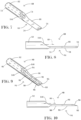
- a surgical instrument 20 comprises a cylindrical shaft 22 and a blade 24 at a distal or free end of the shaft, the blade being unitary and continuous with the shaft, without an intervening joint.
- Instrument 20 typically further comprises a radially or transversely enlarged proximal end portion 26 at a proximal end of the shaft 22 opposite blade 24.
- Proximal end portion 26 is configured for attachment to an electromechanical transducer device (not shown) such as a piezo-electric stack housed inside an instrument hand piece (not shown).
- Shaft 22 has a longitudinal axis 28 and blade 24 includes a flat or planar blade body 30 with a proximal end 32 eccentrically disposed relative to shaft axis 28.
- blade body 30 or at least a proximal end portion thereof is disposed eccentrically relative to shaft 28.
- a blade in each embodiment of an ultrasonic surgical instrument in accordance with the claimed invention, includes a flat or planar blade body with a proximal end eccentrically disposed relative to a shaft axis.
- the blade body or at least a proximal end portion thereof is disposed eccentrically relative to the instrument shaft.
- blade body 30 has at least one edge or peripheral surface 34 that is an endless cylindrical section or perimetral surface continuous and coaxial with a cylindrical outer surface 36 of shaft 22.
- Each embodiment of an ultrasonic surgical instrument disclosed herein has a blade body with at least one edge or peripheral surface in the form of a cylindrical section continuous and coaxial with a cylindrical outer surface of the instrument shaft.
- a method for manufacturing surgical instrument 20 comprises providing a tool blank 38 including an enlarged connector portion 26 ( FIG. 1 ) at one end and a cylindrical shaft 40 at an opposite end and machining a distal end portion 42 of the cylindrical shaft on opposing sides (not designated) thereof to form the shaft portion 22 ( FIG. 1 ) of instrument 20 from cylindrical shaft 40 of the blank 38 and to generate two opposing flats or major blade surfaces 44 and 46.
- the formation of flats 44 and 46 realizes the blade portion 24 ( FIGS. 1-5 ) as a planar shaft extension or end portion having edge or peripheral surface 34.
- blade body 30 extends at an angle a1 with respect to shaft axis 28 and intersects the shaft axis.
- Shaft 22 has an end face 48 contiguous with the proximal end 32 of blade body 30 and additionally has a channel or bore 50 with an outlet 52 in the end face 48.
- Flats 44 and 46 are a planar first major lateral surface and a planar second major lateral surface facing oppositely to one another.
- a rotating cutting tool (schematically depicted at 49) is used to cut flats 44 and 46 from distal end portion 42 ( FIG. 6 ) of blank 38.
- the rotating cutting tool has a circular or cylindrical cutting face (not separately designated) that is moved along a first linear path 51 ( FIG. 6 ) so as to exhibit an oblate oval cutting envelope 54, as shown in FIG. 6 .
- Shaft end face 48 is formed simultaneously with the formation of a proximal end portion of flat 44 by the same cutting action and accordingly takes the form of a cylindrical section.
- end face 48 may be separately and additionally machined in a supplemental process to provide the end face with a planar form.
- the same rotating cutting tool 49 may be used to form lower flat 46, as schematically indicated by another oblate oval cutting envelope 56, as shown in FIG. 6 .
- blade 24 is provided in flat or major lateral surface 44 with a groove 150 continuous with a channel or bore 50 at outlet 52. Blade 24 is further formed so as to exhibit a through hole 152 at an end of groove 150 opposite end face 48 and outlet 52. Groove 150 extends from outlet 52 to through hole 152. As shown in FIG. 5 , flat or major lateral surface 46 is formed with an additional groove 154 communicating with through hole 152. Groove 154 is tapered from a wide end at through hole 152 and a closed narrow end 156 at flat or major lateral surface 46. Surface 46 is in the form of an annular oval surface with an oval center edge 158 formed by through hole 152 and groove 154.
- a blade extends parallel to an axis of an elongate linear instrument shaft and to one side of that axis. Accordingly, each blade body necessarily has a proximal end that is unitary with the distal end of the shaft at a point that is eccentrically disposed relative to the shaft, i.e., at a distance from the shaft axis.
- the various blades are produced by machining a blank in the form of a tubular rod with a cutting tool having a circular cutting edge or cylindrical cutting surface, with that cutting tool being moved along a path parallel to the shaft axis.
- the distal end faces of the shafts may have a cylindrically concave surface produced by the circular or cylindrical cutting tool or may be flat as illustrated, which shape is rendered by further machining, for instance, by moving the circular or cylindrical cutting surface along a linear path at an angle from the shaft axis.
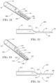
- a surgical instrument 60 comprises a cylindrical shaft 62 and a blade 64 at a distal or free end of the shaft, the blade being unitary and continuous with the shaft, without an intervening joint.
- Instrument 60 further comprises a radially or transversely enlarged proximal end portion 26 ( FIG. 1 ) at a proximal end of the shaft 62 opposite blade 64 or connecting to an electromechanical transducer device (not shown) such as a piezo-electric stack housed inside an instrument hand piece (not shown).
- Blade 64 has a planar upper major surface 66 facing an axis 68 of instrument shaft 62 and a planar lower major surface 70 facing in the opposite direction, away from axis 68. Surfaces 66 and 70 are parallel to one another and to axis 68. Blade 64 is spaced at such a distance from axis 68 that no groove is formed in upper surface 66.
- a channel or lumen 72 of shaft 62 has an outlet port 74 over a proximal end of surface 66 so that irrigant flowing under pressure through the channel or lumen empties out onto surface 66.
- Blade 64 has a distal end face 76 that is flat and oriented perpendicularly to shaft axis 68. Blade 64 has a pair of lateral peripheral edge surfaces 78 that are cylindrical sections continuous and coaxial with an outer surface (not separately designated) of shaft 62.
- a surgical instrument 80 comprises a cylindrical shaft 82 and a blade 84 at a distal or free end of the shaft, the blade being unitary and continuous with the shaft, without an intervening joint.
- Instrument 80 further comprises a radially or transversely enlarged proximal end portion 26 ( FIG. 1 ) at a proximal end of the shaft 82 opposite blade 84 or connecting to an electromechanical transducer device (not shown) such as a piezo-electric stack housed inside an instrument hand piece (not shown).
- Blade 84 has a planar upper major surface 86 facing an axis 88 of instrument shaft 82 and a planar lower major surface 90 facing in the opposite direction, away from axis 88. Surfaces 86 and 90 are parallel to one another and to axis 88. Blade 84 is spaced at such a distance from axis 68 that an elongate groove 91 is formed in upper surface 86. Groove 91 is continuous and coaxial with a cylindrical surface (not separately designated) of a channel or lumen 92 of shaft 82 and communicates with the channel or lumen via an outlet port 94 thereof.
- Blade 84 has a beveled distal end face 96 that is flat with a straight terminal edge 93 and rounded corners 95 and oriented at an angle to shaft axis 88. Groove 91 terminates in or at beveled distal end face 96. Blade 84 has a pair of lateral peripheral edge surfaces 98 that are cylindrical sections continuous and coaxial with an outer surface (not separately designated) of shaft 82.
- FIGS. 11 and 12 depict a surgical instrument 100 that is identical to instrument 80 except for the provision of a through slot 102 in blade 84.
- Reference numbers in FIGS. 11 and 12 are the same as those designating like features or elements of surgical instrument 80.
- Slot 102 is formed in groove 91, essentially midway along the length thereof, and divides the groove into a proximal groove segment 104 and a distal groove segment 106. Slot 102 facilitates the flow of irrigant from groove 91 or groove segment 104 to under surface 90.
- a surgical instrument 110 comprises a cylindrical shaft 112 and a blade 114 at a distal or free end of the shaft, the blade being unitary and continuous with the shaft, without an intervening joint.
- Instrument 110 further comprises a radially or transversely enlarged proximal end portion 26 ( FIG. 1 ) at a proximal end of the shaft 112 opposite blade 114 or connecting to an electromechanical transducer device (not shown) such as a piezo-electric stack housed inside an instrument hand piece (not shown).
- Blade 114 has a planar upper major surface 116 facing an axis 118 of instrument shaft 112 and a planar lower major surface 120 facing in the opposite direction, away from axis 118. Surfaces 116 and 120 are parallel to one another and to axis 118. Blade 114 is spaced at such a distance from axis 118 that a short groove section 121 is formed in upper surface 116, where the groove section is continuous and coaxial with a cylindrical surface (not separately designated) of a channel or lumen 122 of shaft 112 and communicates with the channel or lumen via an outlet port 124 thereof. Blade 114 is also provided with an elongate through slot 126 extending parallel to shaft axis 118.
- blade 114 At a distal end of through slot 126, blade 114 has a distal groove section 128 that extends from slot 126 on one side to a circular edge or cylindrical end surface 130 on an opposite side. Blade 114 has a pair of lateral peripheral edge surfaces 132 that are cylindrical sections continuous and coaxial with an outer surface (not separately designated) of shaft 112.
- irrigant flows under pressure through channel or lumen 122 and into proximal groove section 121 and then into slot 126 from which the irrigant may exit onto both major blade surfaces 116 and 120 and to circular edge or cylindrical end surface 130.
- FIGS. 15 and 16 depict a surgical instrument 140 that is identical to instrument 110 except for a beveling at the distal end of the instrument. Reference numbers in FIGS. 15 and 16 are the same as those designating like features or elements of surgical instrument 110 in FIGS. 13 and 14 .
- Instrument 140 has a beveled end surface 142.
- Distal groove section 128 is truncated by the formation of beveled end surface 142 and exhibits a tapering which facilitates distribution of irrigant from slot 126 over beveled end surface 142.
- the instrument shaft 22, 62, 82, 112 has an end face 48, 144, 146, 148 contiguous with a proximal end of the blade 24, 64, 84, 114 and also has a channel or bore 50, 72, 92, 122 with an outlet 52, 74, 94, 114 in that end face.
- the blade 24, 64, 84, 114 may be provided in a major lateral surface or flat 44, 86, 116 with a groove 91, 104, 121 continuous with the channel or bore 50, 92, 122 at the outlet 52, 94, 114 thereof.
- the groove 91 may extend the length of the blade to a distal end of the blade.
- the groove includes a section 104, 121 extending from the outlet 94, 124 of the shaft channel or bore 92, 112 to a proximal side of the through slot or hole 102, 126.
- the blade 84, 140 may be provided at a distal end, opposite the shaft 82, 112, with a beveled surface 96, 142 inclined with respect to the axis 88, 143 ( FIG. 16 ).
- the blade 24, 114 may be formed with an arcuate distal tip, where the distal tip has a circular or cylindrical surface with an axis oriented perpendicular to the shaft axis.
- a method for manufacturing a unitary ultrasonic surgical instrument having a shaft portion 22, 62, 82, 112 and a blade portion 24, 64, 84, 114 at a distal or free end of the shaft comprises providing a tool blank 38 including an enlarged connector portion 26 at one end and a cylindrical shaft 40 at an opposite end and machining a distal end portion 42 of the cylindrical shaft on opposing sides thereof to form the shaft portion 22, 62, 82, 112 from the cylindrical shaft and to generate two opposing flats 44, 66, 86, 116 and 46, 70, 90, 120.
- the formation of the flats 44, 66, 86, 116 and 46, 70, 90, 120 realizes the blade portion 24, 64, 84, 114 as a planar shaft extension or end portion that may have at least one edge surface 34, 78, 98, 132 that is a cylindrical section continuous and coaxial with a cylindrical outer surface of the shaft portion 22, 62, 82, 112.
- the machining of the distal end portion 42 of the cylindrical shaft 40 of the tool blank 38 typically includes rotating cutting tool 49 about a rotation axis extending parallel to at least one of the flats 44, 66, 86, 116 (perpendicular to the plane of the drawing in FIG. 6 ).
- Distal end portion 42 of the cylindrical shaft 40 of the tool blank 38 may be further machined along edge surfaces 34, 78, 98, 132, for instance, to taper the blade portion 24, 64, 84, 114, that is to reduce the free-end width thereof.
- the machining of the distal end portion 42 of the cylindrical shaft 40 typically includes forming an end surface 48, 144, 146, 148of the shaft portion 22, 62, 82, 112 as a cylindrical section (not shown) having an axis parallel to the rotation axis of the tool 49 and one or both flats 44, 66, 86, 116 and 46, 70, 90, 120. Further machining, either with tool 49 or a different tool can be undertaken to form shaft end surfaces 48, 144, 146, 148 as flat or planer surfaces inclined with respect to shaft axes 28, 68, 88, 118.
Landscapes
- Health & Medical Sciences (AREA)
- Engineering & Computer Science (AREA)
- Surgery (AREA)
- Life Sciences & Earth Sciences (AREA)
- Mechanical Engineering (AREA)
- Heart & Thoracic Surgery (AREA)
- General Health & Medical Sciences (AREA)
- Biomedical Technology (AREA)
- Dentistry (AREA)
- Medical Informatics (AREA)
- Molecular Biology (AREA)
- Animal Behavior & Ethology (AREA)
- Nuclear Medicine, Radiotherapy & Molecular Imaging (AREA)
- Public Health (AREA)
- Veterinary Medicine (AREA)
- Oral & Maxillofacial Surgery (AREA)
- Orthopedic Medicine & Surgery (AREA)
- Surgical Instruments (AREA)
- Apparatuses For Generation Of Mechanical Vibrations (AREA)
Claims (12)
- Verfahren zur Herstellung eines einheitlichen chirurgischen Ultraschallinstruments (20) mit einem zylindrischen Schaftabschnitt (22) und einem Klingenabschnitt (24) an einem distalen oder freien Ende des zylindrischen Schaftabschnitts (22), wobei der Klingenabschnitt (24) einheitlich und kontinuierlich mit dem zylindrischen Schaftabschnitt (22) ist, ohne eine dazwischenliegende Verbindung, wobei das Verfahren umfasst:Bereitstellen eines Werkzeugrohlings (38) mit einem vergrößerten Verbindungsabschnitt (26) an einem Ende und einem zylindrischen Schaft (40) an einem gegenüberliegenden Ende; undBearbeiten eines distalen Endabschnitts (42) des zylindrischen Schafts (40) auf dessen gegenüberliegenden Seiten, um den zylindrischen Schaftabschnitt (22) aus dem zylindrischen Schaft (40) zu formen und zwei gegenüberliegende Abflachungen (44, 46) zu erzeugen,wodurch ein ebener oder flacher Klingenkörper (30) als eine ebene Schaftverlängerung oder ein ebener Endabschnitt gebildet wird, wobei die Bearbeitung des distalen Endabschnitts (42) des zylindrischen Schafts (40) das Ausbilden des ebenen oder flachen Klingenkörpers (30) umfasst, um ein proximales Ende (32) zu haben, das relativ zur Längsachse (28) des zylindrischen Schaftabschnitts (22) exzentrisch angeordnet ist und sich unter einem Winkel (a1) in Bezug auf die Achse (28) erstreckt, der die Achse (28) schneidet.
- Verfahren nach Anspruch 1, bei dem durch die Bearbeitung des distalen Endabschnitts (42) des zylindrischen Schafts (40) an den gegenüberliegenden Seiten desselben der Klingenabschnitt (24) so geformt wird, dass er mindestens eine Kantenfläche (34) aufweist, die ein zylindrischer oder perimetraler Abschnitt ist, der kontinuierlich und koaxial zu einer zylindrischen Außenfläche des zylindrischen Schaftabschnitts (22) verläuft.
- Verfahren nach Anspruch 1 oder 2, wobei die Bearbeitung des distalen Endabschnitts (42) des zylindrischen Schafts (40) das Drehen eines Schneidwerkzeugs (49) um eine Drehachse einschließt, die sich parallel zu mindestens einer der beiden gegenüberliegenden Abflachungen (44, 46) erstreckt.
- Verfahren nach Anspruch 3, wobei die Bearbeitung des distalen Endabschnitts (42) des zylindrischen Schafts (40) das Ausbilden einer Endfläche (48) des zylindrischen Schaftabschnitts (22) als zylindrischer Abschnitt mit einer Achse parallel zu der Drehachse des Schneidwerkzeugs (49) und der mindestens einen der beiden gegenüberliegenden Abflachungen (44, 46) umfasst.
- Verfahren nach Anspruch 3 oder 4, bei dem das rotierende Schneidwerkzeug (49) eine kreisförmige oder zylindrische Schneidfläche aufweist und die Bearbeitung des distalen Endabschnitts (42) des zylindrischen Schafts (40) das Bewegen der kreisförmigen oder zylindrischen Schneidfläche entlang einer ersten linearen Bahn (51) einschließt, so dass eine abgeflachte ovale Schneidhülle (54) entsteht.
- Ein einheitliches chirurgisches Ultraschallinstrument (20) mit einem zylindrischen Schaftabschnitt (22) und einem Klingenabschnitt (24) an einem distalen oder freien Ende des zylindrischen Schaftabschnitts (22), wobei ein ebener oder flacher Klingenkörper (30) als eine ebene Schaftverlängerung oder ein ebener Endabschnitt durch die Bearbeitung zweier gegenüberliegender Abflachungen (44, 46) gebildet wird, so dass der Klingenabschnitt (24) einstückig und durchgehend mit dem zylindrischen Schaftabschnitt (22) ist, ohne eine dazwischenliegende Verbindung, wobei der ebene oder flache Klingenkörper (30) ein proximales Ende (32) aufweist, das exzentrisch in Bezug auf die Längsachse (28) des zylindrischen Schaftabschnitts (22) angeordnet ist und sich in einem Winkel (a1) in Bezug auf die Achse (28) erstreckt und die Achse (28) schneidet.
- Das einheitliche chirurgische Ultraschallinstrument (20) nach Anspruch 6, wobei der ebene oder flache Klingenkörper (30) durch maschinelle Bearbeitung eines distalen oder freien Endabschnitts (42) eines zylindrischen Schafts (40) gebildet wird, wobei die maschinelle Bearbeitung das Drehen eines Schneidwerkzeugs (49) um eine Drehachse einschließt, die sich parallel zu mindestens einer der beiden gegenüberliegenden Flächen (44, 46) erstreckt.
- Das im vorhergehenden Anspruch definierte einheitliche chirurgische Ultraschallinstrument (20), wobei der zylindrische Schaftteil (22) eine Endfläche (48) in Form eines zylindrischen Abschnitts aufweist, dessen Achse parallel zu der Drehachse und der mindestens einen der beiden gegenüberliegenden Abflachungen (44, 46) verläuft.
- Das einheitliche chirurgische Ultraschallinstrument (20) nach Anspruch 6, wobei der Klingenabschnitt (24) mindestens eine Kantenfläche (34) aufweist, die ein zylindrischer Abschnitt ist, der kontinuierlich und koaxial zu einer zylindrischen Außenfläche des zylindrischen Schaftabschnitts (22) verläuft.
- Das einheitliche chirurgische Ultraschallinstrument (20) nach einem der vorhergehenden Ansprüche, wobei der zylindrische Schaftabschnitt (22) eine Endfläche (48) aufweist, die an ein proximales Ende des Klingenabschnitts (24) angrenzt, und auch einen Kanal oder eine Bohrung (50) mit einem Auslass (52) in dieser Endfläche (48) aufweist.
- Das im vorhergehenden Anspruch definierte einheitliche chirurgische Ultraschallinstrument (20), bei dem der Klingenabschnitt (24) in einer Hauptseitenfläche oder -ebene (44) mit einer Rille (91) versehen ist, die mit dem Kanal oder der Bohrung (50) an dessen/deren Auslass (52) zusammenhängt.
- Das in einem der vorhergehenden Ansprüche definierte einheitliche chirurgische Ultraschallinstrument (20) ist ein Ablations- oder Knochenschneideinstrument.
Priority Applications (1)
| Application Number | Priority Date | Filing Date | Title |
|---|---|---|---|
| EP24191852.3A EP4464266A3 (de) | 2016-05-05 | 2017-04-24 | Verfahren zur herstellung eines chirurgischen ultraschallinstruments und instrument |
Applications Claiming Priority (3)
| Application Number | Priority Date | Filing Date | Title |
|---|---|---|---|
| US15/147,323 US10405875B2 (en) | 2016-05-05 | 2016-05-05 | Ultrasonic surgical instrument and method for manufacturing same |
| EP17793008.8A EP3451952B1 (de) | 2016-05-05 | 2017-04-24 | Chirurgisches ultraschallinstrument |
| PCT/US2017/029124 WO2017192288A1 (en) | 2016-05-05 | 2017-04-24 | Ultrasonic surgical instrument and method for manufacturing same |
Related Parent Applications (2)
| Application Number | Title | Priority Date | Filing Date |
|---|---|---|---|
| EP17793008.8A Division-Into EP3451952B1 (de) | 2016-05-05 | 2017-04-24 | Chirurgisches ultraschallinstrument |
| EP17793008.8A Division EP3451952B1 (de) | 2016-05-05 | 2017-04-24 | Chirurgisches ultraschallinstrument |
Related Child Applications (2)
| Application Number | Title | Priority Date | Filing Date |
|---|---|---|---|
| EP24191852.3A Division EP4464266A3 (de) | 2016-05-05 | 2017-04-24 | Verfahren zur herstellung eines chirurgischen ultraschallinstruments und instrument |
| EP24191852.3A Division-Into EP4464266A3 (de) | 2016-05-05 | 2017-04-24 | Verfahren zur herstellung eines chirurgischen ultraschallinstruments und instrument |
Publications (3)
| Publication Number | Publication Date |
|---|---|
| EP4129217A1 EP4129217A1 (de) | 2023-02-08 |
| EP4129217B1 true EP4129217B1 (de) | 2024-07-31 |
| EP4129217B8 EP4129217B8 (de) | 2024-09-11 |
Family
ID=60203209
Family Applications (3)
| Application Number | Title | Priority Date | Filing Date |
|---|---|---|---|
| EP17793008.8A Active EP3451952B1 (de) | 2016-05-05 | 2017-04-24 | Chirurgisches ultraschallinstrument |
| EP22196982.7A Active EP4129217B8 (de) | 2016-05-05 | 2017-04-24 | Verfahren zur herstellung eines chirurgischen ultraschallinstruments und instrument |
| EP24191852.3A Pending EP4464266A3 (de) | 2016-05-05 | 2017-04-24 | Verfahren zur herstellung eines chirurgischen ultraschallinstruments und instrument |
Family Applications Before (1)
| Application Number | Title | Priority Date | Filing Date |
|---|---|---|---|
| EP17793008.8A Active EP3451952B1 (de) | 2016-05-05 | 2017-04-24 | Chirurgisches ultraschallinstrument |
Family Applications After (1)
| Application Number | Title | Priority Date | Filing Date |
|---|---|---|---|
| EP24191852.3A Pending EP4464266A3 (de) | 2016-05-05 | 2017-04-24 | Verfahren zur herstellung eines chirurgischen ultraschallinstruments und instrument |
Country Status (6)
| Country | Link |
|---|---|
| US (4) | US10405875B2 (de) |
| EP (3) | EP3451952B1 (de) |
| JP (1) | JP7128745B2 (de) |
| CN (2) | CN109310453B (de) |
| ES (2) | ES2934788T3 (de) |
| WO (1) | WO2017192288A1 (de) |
Families Citing this family (11)
| Publication number | Priority date | Publication date | Assignee | Title |
|---|---|---|---|---|
| US10405875B2 (en) * | 2016-05-05 | 2019-09-10 | Misonix, Incorporated | Ultrasonic surgical instrument and method for manufacturing same |
| US11832890B2 (en) * | 2018-04-17 | 2023-12-05 | Acclarent, Inc. | Curette with navigation sensor |
| CA3111694A1 (en) * | 2018-09-24 | 2020-04-02 | Bosonic Ag | Device and method for perforating a dense bone layer |
| US11406414B2 (en) | 2018-10-23 | 2022-08-09 | Stryker European Operations Holdings Llc | Ultrasonic cutting tip for lumbar procedures |
| US12279787B2 (en) | 2020-02-27 | 2025-04-22 | Misonix, Llc | Spinal surgery method |
| JP7675823B2 (ja) | 2020-12-18 | 2025-05-13 | ストライカー・ユーロピアン・オペレーションズ・リミテッド | 空冷式ブロードナイフ及び灌流スリーブを伴う超音波手術用アセンブリ |
| USD974558S1 (en) | 2020-12-18 | 2023-01-03 | Stryker European Operations Limited | Ultrasonic knife |
| US12402905B2 (en) | 2021-08-13 | 2025-09-02 | Misonix, Llc | Serrated ultrasonic cutting blade with varied tooth pitch |
| US12594091B2 (en) | 2022-01-03 | 2026-04-07 | Misonix, Llc | Ultrasonic surgical instrument with probe at angle to handpiece |
| CN116763421B (zh) * | 2023-08-18 | 2023-11-24 | 西南石油大学 | 一种具有止血功能的医用刨削刀头 |
| WO2025245715A1 (zh) * | 2024-05-29 | 2025-12-04 | 安速康医疗(苏州)有限公司 | 超声手术刀用刀杆、刀具组件及超声手术刀 |
Family Cites Families (200)
| Publication number | Priority date | Publication date | Assignee | Title |
|---|---|---|---|---|
| US16208A (en) * | 1856-12-09 | Mode of incorporating bituminous liquids with wet earths for a cement | ||
| US2349959A (en) * | 1941-02-20 | 1944-05-30 | Kearney & Trecker Corp | Cutting tool |
| US2753666A (en) * | 1952-01-18 | 1956-07-10 | Elmer C Sasse | Scissors sharpener |
| US3368280A (en) * | 1966-03-23 | 1968-02-13 | C & B Inc | Dental tool |
| US3680610A (en) | 1971-03-04 | 1972-08-01 | Wallace I Lindgren | Sabre saw blade structure |
| US3805787A (en) | 1972-06-16 | 1974-04-23 | Surgical Design Corp | Ultrasonic surgical instrument |
| US4188952A (en) | 1973-12-28 | 1980-02-19 | Loschilov Vladimir I | Surgical instrument for ultrasonic separation of biological tissue |
| US4425115A (en) | 1977-12-19 | 1984-01-10 | Wuchinich David G | Ultrasonic resonant vibrator |
| FR2584916B1 (fr) | 1985-07-19 | 1990-05-25 | Satelec Soc | Appareil de curetage ou d'exerese de tissus biologiques par un instrument vibrant a des frequences ultrasonores |
| US4988334A (en) | 1986-04-09 | 1991-01-29 | Valleylab, Inc. | Ultrasonic surgical system with aspiration tubulation connector |
| US5180363A (en) * | 1989-04-27 | 1993-01-19 | Sumitomo Bakelite Company Company Limited | Operation device |
| US5163433A (en) | 1989-11-01 | 1992-11-17 | Olympus Optical Co., Ltd. | Ultrasound type treatment apparatus |
| US5176677A (en) | 1989-11-17 | 1993-01-05 | Sonokinetics Group | Endoscopic ultrasonic rotary electro-cauterizing aspirator |
| US5222937A (en) | 1991-01-11 | 1993-06-29 | Olympus Optical Co., Ltd. | Ultrasonic treatment apparatus |
| US5261922A (en) | 1992-02-20 | 1993-11-16 | Hood Larry L | Improved ultrasonic knife |
| US5695510A (en) | 1992-02-20 | 1997-12-09 | Hood; Larry L. | Ultrasonic knife |
| JP2523249B2 (ja) | 1992-06-30 | 1996-08-07 | 公也 清水 | 超音波手術器 |
| US5517889A (en) | 1992-07-28 | 1996-05-21 | Logan; Patrick K. | Saw blade |
| US5312329A (en) | 1993-04-07 | 1994-05-17 | Valleylab Inc. | Piezo ultrasonic and electrosurgical handpiece |
| US5371429A (en) | 1993-09-28 | 1994-12-06 | Misonix, Inc. | Electromechanical transducer device |
| US5484398A (en) | 1994-03-17 | 1996-01-16 | Valleylab Inc. | Methods of making and using ultrasonic handpiece |
| US5531597A (en) * | 1994-06-30 | 1996-07-02 | Dentsply Research & Development Corp. | Transducer activated tool tip |
| US5527273A (en) | 1994-10-06 | 1996-06-18 | Misonix, Inc. | Ultrasonic lipectomy probe and method for manufacture |
| US6602248B1 (en) | 1995-06-07 | 2003-08-05 | Arthro Care Corp. | Methods for repairing damaged intervertebral discs |
| US6264650B1 (en) | 1995-06-07 | 2001-07-24 | Arthrocare Corporation | Methods for electrosurgical treatment of intervertebral discs |
| US6726684B1 (en) | 1996-07-16 | 2004-04-27 | Arthrocare Corporation | Methods for electrosurgical spine surgery |
| CA2213948C (en) | 1996-09-19 | 2006-06-06 | United States Surgical Corporation | Ultrasonic dissector |
| US6036667A (en) | 1996-10-04 | 2000-03-14 | United States Surgical Corporation | Ultrasonic dissection and coagulation system |
| JP3791987B2 (ja) | 1996-10-31 | 2006-06-28 | 株式会社ニデック | 超音波手術装置 |
| US6582440B1 (en) | 1996-12-26 | 2003-06-24 | Misonix Incorporated | Non-clogging catheter for lithotrity |
| US5769211A (en) | 1997-01-21 | 1998-06-23 | Misonix, Inc. | Medical handpiece with autoclavable switch |
| US5976105A (en) | 1997-03-05 | 1999-11-02 | Marcove; Ralph C. | Intra annular ultrasound disc apparatus and method |
| US5906595A (en) | 1997-04-25 | 1999-05-25 | Ethicon Endo-Surgery, Inc. | Trocar having protector with flexible end and improved seal assembly |
| US6270471B1 (en) | 1997-12-23 | 2001-08-07 | Misonix Incorporated | Ultrasonic probe with isolated outer cannula |
| US6033375A (en) | 1997-12-23 | 2000-03-07 | Fibrasonics Inc. | Ultrasonic probe with isolated and teflon coated outer cannula |
| DE19806718A1 (de) * | 1998-02-18 | 1999-08-26 | Storz Endoskop Gmbh | Vorrichtung zur Behandlung von Körpergewebe mittels Ultraschall |
| US7892229B2 (en) | 2003-01-18 | 2011-02-22 | Tsunami Medtech, Llc | Medical instruments and techniques for treating pulmonary disorders |
| US7494488B2 (en) | 1998-05-28 | 2009-02-24 | Pearl Technology Holdings, Llc | Facial tissue strengthening and tightening device and methods |
| US6309400B2 (en) * | 1998-06-29 | 2001-10-30 | Ethicon Endo-Surgery, Inc. | Curved ultrasonic blade having a trapezoidal cross section |
| US6799729B1 (en) | 1998-09-11 | 2004-10-05 | Misonix Incorporated | Ultrasonic cleaning and atomizing probe |
| US6256859B1 (en) | 1998-09-25 | 2001-07-10 | Sherwood Services Ag | Method of manufacturing an aspiring tool |
| US6375648B1 (en) | 1998-10-02 | 2002-04-23 | Misonix Incorporated | Infiltration cannula with teflon coated outer surface |
| US6461314B1 (en) | 1999-02-02 | 2002-10-08 | Transurgical, Inc. | Intrabody hifu applicator |
| US6613056B1 (en) | 1999-02-17 | 2003-09-02 | Misonix, Inc. | Ultrasonic probe with low-friction bushings |
| US6492762B1 (en) | 1999-03-22 | 2002-12-10 | Transurgical, Inc. | Ultrasonic transducer, transducer array, and fabrication method |
| US6454730B1 (en) | 1999-04-02 | 2002-09-24 | Misonix Incorporated | Thermal film ultrasonic dose indicator |
| WO2001035812A2 (en) * | 1999-11-15 | 2001-05-25 | Misonix Incorporated | Ultrasonic cutting blade with cooling |
| US6443969B1 (en) * | 2000-08-15 | 2002-09-03 | Misonix, Inc. | Ultrasonic cutting blade with cooling |
| US6379371B1 (en) | 1999-11-15 | 2002-04-30 | Misonix, Incorporated | Ultrasonic cutting blade with cooling |
| US6352532B1 (en) | 1999-12-14 | 2002-03-05 | Ethicon Endo-Surgery, Inc. | Active load control of ultrasonic surgical instruments |
| US6494714B1 (en) | 2000-01-24 | 2002-12-17 | Dentsply Research & Development Corp. | Method of making a tool tip and tool tip |
| US6787974B2 (en) | 2000-03-22 | 2004-09-07 | Prorhythm, Inc. | Ultrasound transducer unit and planar ultrasound lens |
| DE20019711U1 (de) | 2000-11-20 | 2002-04-04 | Söring GmbH, 25451 Quickborn | Ultraschall-Gerät zur Behandlung septischer Wunden |
| US8348880B2 (en) * | 2001-04-04 | 2013-01-08 | Ethicon Endo-Surgery, Inc. | Ultrasonic surgical instrument incorporating fluid management |
| US6736814B2 (en) | 2002-02-28 | 2004-05-18 | Misonix, Incorporated | Ultrasonic medical treatment device for bipolar RF cauterization and related method |
| US6648839B2 (en) | 2002-02-28 | 2003-11-18 | Misonix, Incorporated | Ultrasonic medical treatment device for RF cauterization and related method |
| US11202676B2 (en) | 2002-03-06 | 2021-12-21 | Mako Surgical Corp. | Neural monitor-based dynamic haptics |
| US7442168B2 (en) | 2002-04-05 | 2008-10-28 | Misonix, Incorporated | High efficiency medical transducer with ergonomic shape and method of manufacture |
| US20030204199A1 (en) | 2002-04-30 | 2003-10-30 | Novak Theodore A. D. | Device and method for ultrasonic tissue excision with tissue selectivity |
| US7776027B2 (en) | 2002-07-11 | 2010-08-17 | Misonix, Incorporated | Medical handpiece with automatic power switching means |
| DE20303777U1 (de) | 2002-07-22 | 2003-12-11 | Söring GmbH | Medizinisches Behandlungsgerät |
| US20050142515A1 (en) | 2002-12-12 | 2005-06-30 | Hiam Levy | Dental tool having a hand grip |
| US8057468B2 (en) | 2002-12-17 | 2011-11-15 | Bovie Medical Corporation | Method to generate a plasma stream for performing electrosurgery |
| US6875220B2 (en) | 2002-12-30 | 2005-04-05 | Cybersonics, Inc. | Dual probe |
| US20040265776A1 (en) * | 2003-03-13 | 2004-12-30 | Tipton David W. | Ultrasonic insert with internal flow channel |
| IL155546A (en) | 2003-04-22 | 2010-06-16 | Healfus Ltd | Apparatus for treatment of damaged tissue |
| US20050033292A1 (en) | 2003-05-30 | 2005-02-10 | Teitelbaum George P. | Methods and devices for transpedicular discectomy |
| IL157696A0 (en) | 2003-09-01 | 2004-03-28 | Hawk Medical Technologies Ltd | Apparatus and method for removing a pigmented section of skin |
| US7522955B2 (en) | 2003-10-03 | 2009-04-21 | Michael Rontal | Method and apparatus for the ultrasonic cleaning of biofilm coated surfaces |
| CA2545101A1 (en) | 2003-11-06 | 2005-05-26 | Misonix Incorporated | Rf cauterization and ultrasonic ablation instrument with multi-hole collar and electrode mounting sleeve |
| US8221424B2 (en) | 2004-12-20 | 2012-07-17 | Spinascope, Inc. | Surgical instrument for orthopedic surgery |
| US7223267B2 (en) | 2004-02-06 | 2007-05-29 | Misonix, Incorporated | Ultrasonic probe with detachable slidable cauterization forceps |
| CN100394897C (zh) | 2004-08-03 | 2008-06-18 | 张毓笠 | 复合振动的超声骨骼手术仪 |
| US20070213734A1 (en) | 2006-03-13 | 2007-09-13 | Bleich Jeffery L | Tissue modification barrier devices and methods |
| GB0426503D0 (en) | 2004-12-02 | 2005-01-05 | Orthosonics Ltd | Improved osteotome |
| US7931611B2 (en) | 2005-03-23 | 2011-04-26 | Misonix, Incorporated | Ultrasonic wound debrider probe and method of use |
| US8142460B2 (en) | 2005-04-15 | 2012-03-27 | Integra Lifesciences (Ireland) Ltd. | Bone abrading ultrasonic horns |
| US7959438B2 (en) | 2005-08-11 | 2011-06-14 | James Feine | Movable pin ultrasonic transducer |
| US8016843B2 (en) * | 2005-09-09 | 2011-09-13 | Alcon Research Ltd | Ultrasonic knife |
| US20070191713A1 (en) * | 2005-10-14 | 2007-08-16 | Eichmann Stephen E | Ultrasonic device for cutting and coagulating |
| JP4657082B2 (ja) * | 2005-10-28 | 2011-03-23 | オリンパスメディカルシステムズ株式会社 | 超音波治療装置 |
| EP2032059A4 (de) * | 2006-06-05 | 2009-09-16 | Broncus Tech Inc | Vorrichtungen zur erzeugung von durchgängen und zur messung von blutgefässen |
| US7431704B2 (en) | 2006-06-07 | 2008-10-07 | Bacoustics, Llc | Apparatus and method for the treatment of tissue with ultrasound energy by direct contact |
| US8562547B2 (en) | 2006-06-07 | 2013-10-22 | Eliaz Babaev | Method for debriding wounds |
| US8814870B2 (en) | 2006-06-14 | 2014-08-26 | Misonix, Incorporated | Hook shaped ultrasonic cutting blade |
| WO2008014258A2 (en) | 2006-07-24 | 2008-01-31 | Spine Solutions, Inc. | Intervertebral implant with keel |
| US20080058775A1 (en) | 2006-08-29 | 2008-03-06 | Darian Alexander L | Ultrasonic debrider probe and method of use |
| US8025672B2 (en) | 2006-08-29 | 2011-09-27 | Misonix, Incorporated | Ultrasonic wound treatment method and apparatus |
| US8430897B2 (en) | 2006-08-29 | 2013-04-30 | Misonix Incorporated | Ultrasonic wound debrider probe and method of use |
| US20130226042A1 (en) | 2006-10-18 | 2013-08-29 | Misonix Incorporated | Ultrasonic Treatment Method and Apparatus with Active Pain Suppression |
| US9693792B2 (en) | 2006-10-18 | 2017-07-04 | Misonix, Incorporated | Ultrasonic treatment method and apparatus with active pain suppression |
| DE202006017876U1 (de) | 2006-11-24 | 2008-03-27 | Söring GmbH | Knochenstanze |
| US8226675B2 (en) | 2007-03-22 | 2012-07-24 | Ethicon Endo-Surgery, Inc. | Surgical instruments |
| US20080234709A1 (en) | 2007-03-22 | 2008-09-25 | Houser Kevin L | Ultrasonic surgical instrument and cartilage and bone shaping blades therefor |
| WO2008118709A1 (en) | 2007-03-22 | 2008-10-02 | Ethicon Endo-Surgery, Inc. | Ultrasonic surgical instrument blades |
| US8911460B2 (en) * | 2007-03-22 | 2014-12-16 | Ethicon Endo-Surgery, Inc. | Ultrasonic surgical instruments |
| US8109925B2 (en) | 2007-05-25 | 2012-02-07 | Misonix Incorporated | Treatment of breast disease with vibrating device |
| US8353912B2 (en) | 2007-06-01 | 2013-01-15 | Misonix, Incorporated | Ultrasonic spinal surgery method |
| US8659208B1 (en) | 2007-06-14 | 2014-02-25 | Misonix, Inc. | Waveform generator for driving electromechanical device |
| US9070856B1 (en) | 2007-06-14 | 2015-06-30 | Misonix, Incorporated | Waveform generator for driving electromechanical device |
| US20110160624A1 (en) | 2007-07-13 | 2011-06-30 | Bacoustics, Llc | Apparatus for creating a therapeutic solution and debridement with ultrasound energy |
| US8257386B2 (en) * | 2007-09-11 | 2012-09-04 | Cambridge Endoscopic Devices, Inc. | Surgical instrument |
| US9636187B2 (en) | 2007-11-21 | 2017-05-02 | Misonix Incorporated | Atomized-fluid shield for surgery and method of use |
| GB2457249A (en) | 2008-02-06 | 2009-08-12 | Shafir Production Systems Ltd | A rotationally reciprocating cutting tool |
| EP2244642A4 (de) | 2008-02-20 | 2011-07-20 | Mayo Foundation | Systeme, vorrichtungen und verfahren für den zugang zu körpergewebe |
| US8795278B2 (en) | 2008-06-23 | 2014-08-05 | Microfabrica Inc. | Selective tissue removal tool for use in medical applications and methods for making and using |
| US20100022944A1 (en) | 2008-07-21 | 2010-01-28 | Wilcox Robert L | Method and apparatus for treating an acute myocardial infarction |
| US9211155B2 (en) | 2008-08-20 | 2015-12-15 | Prostacare Pty Ltd. | Non-thermal ablation system for treating BPH and other growths |
| US8323220B2 (en) | 2008-09-19 | 2012-12-04 | Eilaz Babaev | Spider vein treatment apparatus |
| US20150157387A1 (en) | 2008-11-12 | 2015-06-11 | Trice Medical, Inc. | Tissue visualization and modification devices and methods |
| US8075578B2 (en) | 2009-03-23 | 2011-12-13 | V.R. Hexis Ltd. | Apparatus and method for making a circular incision |
| US8206306B2 (en) | 2009-05-07 | 2012-06-26 | Hitachi Aloka Medical, Ltd. | Ultrasound systems and methods for orthopedic applications |
| US9788925B2 (en) * | 2009-08-19 | 2017-10-17 | Vicky L Moran | Transducer activated tool with water conduit |
| US20110092880A1 (en) | 2009-10-12 | 2011-04-21 | Michael Gertner | Energetic modulation of nerves |
| US8376970B2 (en) | 2009-10-29 | 2013-02-19 | Eilaz Babaev | Ultrasound apparatus and methods for mitigation of neurological damage |
| USD627463S1 (en) | 2010-01-27 | 2010-11-16 | Misonix, Inc. | Ultrasonic wound treatment probe |
| US8961547B2 (en) | 2010-02-11 | 2015-02-24 | Ethicon Endo-Surgery, Inc. | Ultrasonic surgical instruments with moving cutting implement |
| CA2799717C (en) | 2010-05-21 | 2019-09-03 | Misonix Incorporated | Dual-mode piezocomposite ultrasonic transducer |
| WO2011146139A2 (en) | 2010-05-21 | 2011-11-24 | Misonix Incorporated | Ultrasonic transducer assembly |
| US9364568B2 (en) | 2010-07-15 | 2016-06-14 | Warsaw Orthopedic, Inc. | Methods to diagnose degenerative disc disease |
| TW201208638A (en) * | 2010-08-27 | 2012-03-01 | Univ Nat Taiwan | Tissue treatment tool and signal processing method using the same |
| US10470788B2 (en) | 2010-12-07 | 2019-11-12 | Misonix, Inc | Ultrasonic instrument, associated method of use and related manufacturing method |
| USD644326S1 (en) | 2010-12-16 | 2011-08-30 | Misonix, Incorporated | Ultrasonic wound treatment probe |
| USD680218S1 (en) | 2011-02-04 | 2013-04-16 | Misonix Incorporated | Ultrasonic bone cutting blade |
| KR20120093654A (ko) | 2011-02-15 | 2012-08-23 | 주식회사 비젼플러스메디 | 플라즈마 디스크 치료 장치 |
| US9254142B2 (en) | 2011-04-11 | 2016-02-09 | Iogyn, Inc. | Tissue extraction devices and methods |
| US10548619B2 (en) | 2011-04-29 | 2020-02-04 | Michael P. Wallace | Selective spinal tissue removal apparatus and method |
| CA2836701C (en) | 2011-05-27 | 2019-01-29 | Sm Products, Llc | Reciprocating saw blade |
| US8894673B2 (en) * | 2011-10-07 | 2014-11-25 | Misonix, Incorporated | Ultrasonic osteotome |
| JP2013090809A (ja) | 2011-10-26 | 2013-05-16 | Olympus Corp | 脂肪除去装置 |
| KR20140105744A (ko) | 2011-11-10 | 2014-09-02 | 호메이욘 에이치. 자데흐 | 압전 골 수술용 개선된 수술 팁 |
| US20150066032A1 (en) | 2012-01-05 | 2015-03-05 | Orthosonics Limited | Bone resector |
| EP2809246A1 (de) * | 2012-02-03 | 2014-12-10 | Satelec SAS | Schneidspitzen für chirurgisches ultraschallsystem |
| US20130231528A1 (en) | 2012-03-05 | 2013-09-05 | Misonix Incorporated | Protective sleeve and associated surgical method |
| WO2013142098A2 (en) * | 2012-03-19 | 2013-09-26 | Clinical Innovations, Llc | Surgical instruments and methods of use |
| US9820768B2 (en) | 2012-06-29 | 2017-11-21 | Ethicon Llc | Ultrasonic surgical instruments with control mechanisms |
| US9226767B2 (en) | 2012-06-29 | 2016-01-05 | Ethicon Endo-Surgery, Inc. | Closed feedback control for electrosurgical device |
| EP2883509A4 (de) * | 2012-08-07 | 2016-06-08 | Olympus Corp | Ultraschallsonde und verfahren zur herstellung der ultraschallsonde |
| US10588691B2 (en) | 2012-09-12 | 2020-03-17 | Relievant Medsystems, Inc. | Radiofrequency ablation of tissue within a vertebral body |
| CA2889478C (en) | 2012-11-05 | 2020-11-24 | Relievant Medsystems, Inc. | Systems and methods for creating curved paths through bone and modulating nerves within the bone |
| US20140135804A1 (en) | 2012-11-15 | 2014-05-15 | Ethicon Endo-Surgery, Inc. | Ultrasonic and electrosurgical devices |
| EP2745797B1 (de) | 2012-12-21 | 2017-10-25 | W & H Dentalwerk Bürmoos GmbH | Ein durch Schall antreibbares Schneidwerkzeug |
| US9289227B2 (en) | 2013-03-15 | 2016-03-22 | Kyphon SÀRL | Ultrasonic cutting device |
| US10076349B2 (en) | 2013-03-15 | 2018-09-18 | Misonix, Inc. | Ultrasonic surgical drill and associated surgical method |
| WO2014150526A1 (en) | 2013-03-15 | 2014-09-25 | Misonix, Incorporated | Sheath coupling member and associated instrument assembly |
| WO2014150560A2 (en) * | 2013-03-15 | 2014-09-25 | Misonix, Incorporated | Method for ultrasonic tissue excision with tissue selectivity |
| US9320528B2 (en) | 2013-06-26 | 2016-04-26 | Misonix, Incorporated | Ultrasonic cutting blade with cooling liquid conduction |
| US10398463B2 (en) | 2013-06-28 | 2019-09-03 | Misonix Incorporated | Ultrasonic instrument and method for manufacturing same |
| US9211137B2 (en) | 2013-06-28 | 2015-12-15 | Misonix, Incorporated | Ultrasonic cutting blade with cooling liquid conduction |
| US9387005B2 (en) * | 2013-06-28 | 2016-07-12 | Misonix, Incorporated | Ultrasonic cutting blade with cooling liquid conduction |
| US10182837B2 (en) | 2013-06-28 | 2019-01-22 | Misonix, Inc. | Sheath coupling member and associated instrument assembly |
| US9622766B2 (en) | 2013-08-22 | 2017-04-18 | Misonix Incorporated | Ultrasonic instrument assembly and method for manufacturing same |
| US10117666B2 (en) | 2013-09-26 | 2018-11-06 | Misonix Inc. | Ultrasonic instrument and method using same |
| US20150088137A1 (en) | 2013-09-26 | 2015-03-26 | Misonix Incorporated | Ultrasonic surgical instrument with dual end effector |
| WO2015045198A1 (ja) | 2013-09-27 | 2015-04-02 | オリンパスメディカルシステムズ株式会社 | 処置具及び処置システム |
| CN105592812B (zh) | 2013-09-27 | 2018-04-24 | 奥林巴斯株式会社 | 处理器具及处理系统 |
| US20150094723A1 (en) * | 2013-09-30 | 2015-04-02 | Misonix Incorporated | Ultrasonic surgical apparatus with power reduction |
| US9949751B2 (en) | 2014-02-04 | 2018-04-24 | Misonix, Inc. | Ultrasonic debrider probe |
| IL231751A (en) | 2014-03-27 | 2016-08-31 | Tel Hashomer Medical Res Infrastructure & Services Ltd | Medical device for tissue removal |
| US10398465B2 (en) | 2014-04-29 | 2019-09-03 | Misonix Incorporated | Ultrasonic surgical instrument assembly, related accessory, and associated surgical method |
| CN204133551U (zh) | 2014-06-10 | 2015-02-04 | 曹群 | 超声骨刀刀头和具有其的超声骨刀 |
| US10842587B2 (en) | 2014-11-12 | 2020-11-24 | Misonix, Incorporated | Method for minimally invasive surgery using therapeutic ultrasound to treat spine and orthopedic diseases, injuries and deformities |
| US10299809B2 (en) | 2014-11-12 | 2019-05-28 | Misonix, Incorporated | Method for reducing biofilm formation |
| US10471281B2 (en) | 2014-11-12 | 2019-11-12 | Misonix, Inc. | Method for direct bone stimulation during interventional procedure to assist in bone healing |
| US20160166276A1 (en) * | 2014-12-10 | 2016-06-16 | Haley Huang | Surgical Device |
| US20160175150A1 (en) | 2014-12-18 | 2016-06-23 | Surgical Design Corporation | Ultrasonic handpiece with multiple drivers |
| US9907546B2 (en) | 2015-01-15 | 2018-03-06 | Jan ECKERMANN | Surgical elevator with suction |
| WO2016126855A1 (en) | 2015-02-03 | 2016-08-11 | Tipul Biotechnology, LLC | Devices and methods for electrolytic production of disinfectant solution from salt solution in a container |
| CA2986031C (en) | 2015-05-15 | 2024-03-19 | ClearIt, LLC | Systems and methods for tattoo removal using cold plasma |
| EP3302658B1 (de) | 2015-06-03 | 2019-09-04 | Novopyxis, Inc. | Flüssigkeitsabgabevorrichtungen |
| US10092741B2 (en) | 2015-06-08 | 2018-10-09 | Misonix, Inc. | Ultrasonic surgical apparatus and associated method |
| US11298434B2 (en) | 2015-07-09 | 2022-04-12 | Misonix, Incorporated | Ultrasonic medical probe with failsafe for sterility and associated method |
| US9872697B2 (en) | 2015-07-13 | 2018-01-23 | Misonix, Incorporated | Ultrasonic wound treatment apparatus and associated method |
| US10987129B2 (en) | 2015-09-04 | 2021-04-27 | Medos International Sarl | Multi-shield spinal access system |
| US9603656B1 (en) | 2015-10-23 | 2017-03-28 | RELIGN Corporation | Arthroscopic devices and methods |
| CN111329552B (zh) | 2016-03-12 | 2021-06-22 | P·K·朗 | 包括机器人的用于引导骨切除的增强现实可视化 |
| WO2017180493A1 (en) | 2016-04-15 | 2017-10-19 | Stryker European Holdings I, Llc | Reciprocating saw blade with recessed chip catchments located between the blade teeth |
| US10405875B2 (en) | 2016-05-05 | 2019-09-10 | Misonix, Incorporated | Ultrasonic surgical instrument and method for manufacturing same |
| US10660663B2 (en) | 2016-05-25 | 2020-05-26 | Ethicon Llc | Ultrasonic surgical instrument blade with heat reduction feature |
| US10463381B2 (en) | 2016-07-27 | 2019-11-05 | Misonix, Inc. | Ultrasonic surgical probe, assembly, and related method |
| US10543012B2 (en) | 2016-08-02 | 2020-01-28 | Misonix, Inc. | Ultrasonic surgical device with reduction in electrical interference |
| US10470789B2 (en) | 2017-03-06 | 2019-11-12 | Misonix, Inc. | Method for reducing or removing biofilm |
| US10524846B2 (en) | 2017-04-05 | 2020-01-07 | Warsaw Orthopedic, Inc. | Surgical implant bending system and method |
| IT201700059460A1 (it) | 2017-05-31 | 2018-12-01 | Mectron S P A | Dispositivo ultrasonico di taglio per osteotomia |
| US10687824B2 (en) | 2017-07-21 | 2020-06-23 | Stryker European Holdings I, Llc | Surgical saw and saw blade for use therewith |
| CN107518929B (zh) | 2017-09-14 | 2024-12-13 | 北京水木天蓬医疗技术有限公司 | 超声骨刀刀头 |
| CN107744401B (zh) | 2017-11-14 | 2024-05-07 | 北京水木天蓬医疗技术有限公司 | 超声骨刀刀头 |
| US10835276B2 (en) | 2018-01-11 | 2020-11-17 | Misonix, Incorporated | Ultrasonic surgical system for osseous transection |
| US11540899B2 (en) | 2018-04-04 | 2023-01-03 | Bennett H. Jacoby | Methods and apparatus for periodontal scaling and debridement and gum tissue ablation for treating periodontal and peri-implant disease |
| WO2019204641A1 (en) | 2018-04-20 | 2019-10-24 | Misonix, Incorporated | Ultrasonic surgical drill, assembly and associated surgical method |
| US11007308B2 (en) | 2018-10-24 | 2021-05-18 | Misonix, Incorporated | Fluid handling assembly and related tube set and method for use in surgical procedures |
| CN210249992U (zh) | 2018-12-28 | 2020-04-07 | 北京速迈医疗科技有限公司 | 用于超声手术系统的切骨刀 |
| US20200246056A1 (en) | 2019-02-05 | 2020-08-06 | Covidien Lp | Gas-enhanced energy-based surgical instrument, system, and method for minimally-invasive surgical procedures |
| US11259940B2 (en) | 2019-06-28 | 2022-03-01 | Mis Spine Ip, Llc | Systems and methods for percutaneous spinal interbody fusion (PSIF) |
| US12279787B2 (en) | 2020-02-27 | 2025-04-22 | Misonix, Llc | Spinal surgery method |
| CN116390694A (zh) | 2020-10-25 | 2023-07-04 | 米松尼克斯股份有限公司 | 脊柱外科手术设备 |
| US11672558B2 (en) | 2021-05-21 | 2023-06-13 | Misonix, Llc | Ultrasonic spinal surgery method |
| US12011190B2 (en) | 2021-05-21 | 2024-06-18 | Misonix, Llc | Ultrasonic spinal surgery method and associated surgical instrument |
| US12402905B2 (en) | 2021-08-13 | 2025-09-02 | Misonix, Llc | Serrated ultrasonic cutting blade with varied tooth pitch |
| US12594091B2 (en) | 2022-01-03 | 2026-04-07 | Misonix, Llc | Ultrasonic surgical instrument with probe at angle to handpiece |
-
2016
- 2016-05-05 US US15/147,323 patent/US10405875B2/en active Active
-
2017
- 2017-04-24 EP EP17793008.8A patent/EP3451952B1/de active Active
- 2017-04-24 WO PCT/US2017/029124 patent/WO2017192288A1/en not_active Ceased
- 2017-04-24 CN CN201780036867.4A patent/CN109310453B/zh active Active
- 2017-04-24 ES ES17793008T patent/ES2934788T3/es active Active
- 2017-04-24 EP EP22196982.7A patent/EP4129217B8/de active Active
- 2017-04-24 CN CN202211123593.1A patent/CN115530928A/zh active Pending
- 2017-04-24 EP EP24191852.3A patent/EP4464266A3/de active Pending
- 2017-04-24 JP JP2018558162A patent/JP7128745B2/ja active Active
- 2017-04-24 ES ES22196982T patent/ES2990141T3/es active Active
-
2019
- 2019-08-14 US US16/540,376 patent/US11406413B2/en active Active
- 2019-08-14 US US16/540,532 patent/US11540853B2/en active Active
-
2023
- 2023-01-03 US US18/092,563 patent/US12433629B2/en active Active
Also Published As
| Publication number | Publication date |
|---|---|
| JP2019515746A (ja) | 2019-06-13 |
| ES2990141T3 (es) | 2024-11-28 |
| EP3451952B1 (de) | 2022-10-26 |
| JP7128745B2 (ja) | 2022-08-31 |
| CN115530928A (zh) | 2022-12-30 |
| EP3451952A1 (de) | 2019-03-13 |
| ES2934788T3 (es) | 2023-02-27 |
| US20170319226A1 (en) | 2017-11-09 |
| US20230144990A1 (en) | 2023-05-11 |
| WO2017192288A1 (en) | 2017-11-09 |
| US11406413B2 (en) | 2022-08-09 |
| EP4464266A3 (de) | 2025-01-22 |
| US20190374245A1 (en) | 2019-12-12 |
| EP4129217B8 (de) | 2024-09-11 |
| CN109310453B (zh) | 2022-12-06 |
| US10405875B2 (en) | 2019-09-10 |
| EP3451952A4 (de) | 2019-12-11 |
| EP4129217A1 (de) | 2023-02-08 |
| EP4464266A2 (de) | 2024-11-20 |
| CA3023055A1 (en) | 2017-11-09 |
| CN109310453A (zh) | 2019-02-05 |
| US20190380732A1 (en) | 2019-12-19 |
| US12433629B2 (en) | 2025-10-07 |
| US11540853B2 (en) | 2023-01-03 |
Similar Documents
| Publication | Publication Date | Title |
|---|---|---|
| EP4129217B1 (de) | Verfahren zur herstellung eines chirurgischen ultraschallinstruments und instrument | |
| US5205817A (en) | Surgical instrument | |
| US6443969B1 (en) | Ultrasonic cutting blade with cooling | |
| EP3013259B1 (de) | Ultraschallschneideklinge mit einer kühlflüssigkeitsleitung | |
| CN105451671B (zh) | 具有冷却液体传导的超声波切割刀片 | |
| EP2967593B1 (de) | Chirurgischer ultraschallbohrer | |
| US6423082B1 (en) | Ultrasonic surgical blade with improved cutting and coagulation features | |
| US20260033856A1 (en) | Serrated ultrasonic cutting blade with varied tooth pitch | |
| EP1311197B1 (de) | Ultraschallklinge mit kühlung | |
| CA3023055C (en) | Ultrasonic surgical instrument and method for manufacturing same | |
| HK40083879A (en) | Ultrasonic surgical instrument and method for manufacturing same | |
| HK40003915A (en) | Ultrasonic surgical instrument and method for manufacturing same | |
| HK40003915B (en) | Ultrasonic surgical instrument and method for manufacturing same | |
| EP1138437A2 (de) | Verfahren zum Entgräten von ultraschallgeräten | |
| JPH0481459B2 (de) |
Legal Events
| Date | Code | Title | Description |
|---|---|---|---|
| PUAI | Public reference made under article 153(3) epc to a published international application that has entered the european phase |
Free format text: ORIGINAL CODE: 0009012 |
|
| STAA | Information on the status of an ep patent application or granted ep patent |
Free format text: STATUS: THE APPLICATION HAS BEEN PUBLISHED |
|
| AC | Divisional application: reference to earlier application |
Ref document number: 3451952 Country of ref document: EP Kind code of ref document: P |
|
| AK | Designated contracting states |
Kind code of ref document: A1 Designated state(s): AL AT BE BG CH CY CZ DE DK EE ES FI FR GB GR HR HU IE IS IT LI LT LU LV MC MK MT NL NO PL PT RO RS SE SI SK SM TR |
|
| STAA | Information on the status of an ep patent application or granted ep patent |
Free format text: STATUS: REQUEST FOR EXAMINATION WAS MADE |
|
| 17P | Request for examination filed |
Effective date: 20230802 |
|
| RBV | Designated contracting states (corrected) |
Designated state(s): AL AT BE BG CH CY CZ DE DK EE ES FI FR GB GR HR HU IE IS IT LI LT LU LV MC MK MT NL NO PL PT RO RS SE SI SK SM TR |
|
| GRAP | Despatch of communication of intention to grant a patent |
Free format text: ORIGINAL CODE: EPIDOSNIGR1 |
|
| STAA | Information on the status of an ep patent application or granted ep patent |
Free format text: STATUS: GRANT OF PATENT IS INTENDED |
|
| INTG | Intention to grant announced |
Effective date: 20240222 |
|
| GRAS | Grant fee paid |
Free format text: ORIGINAL CODE: EPIDOSNIGR3 |
|
| GRAA | (expected) grant |
Free format text: ORIGINAL CODE: 0009210 |
|
| STAA | Information on the status of an ep patent application or granted ep patent |
Free format text: STATUS: THE PATENT HAS BEEN GRANTED |
|
| AC | Divisional application: reference to earlier application |
Ref document number: 3451952 Country of ref document: EP Kind code of ref document: P |
|
| AK | Designated contracting states |
Kind code of ref document: B1 Designated state(s): AL AT BE BG CH CY CZ DE DK EE ES FI FR GB GR HR HU IE IS IT LI LT LU LV MC MK MT NL NO PL PT RO RS SE SI SK SM TR |
|
| REG | Reference to a national code |
Ref country code: CH Ref legal event code: EP Ref country code: GB Ref legal event code: FG4D |
|
| RAP2 | Party data changed (patent owner data changed or rights of a patent transferred) |
Owner name: MISONIX, LLC |
|
| REG | Reference to a national code |
Ref country code: DE Ref legal event code: R096 Ref document number: 602017083820 Country of ref document: DE |
|
| REG | Reference to a national code |
Ref country code: CH Ref legal event code: PK Free format text: BERICHTIGUNG B8 |
|
| REG | Reference to a national code |
Ref country code: IE Ref legal event code: FG4D |
|
| P01 | Opt-out of the competence of the unified patent court (upc) registered |
Free format text: CASE NUMBER: APP_43567/2024 Effective date: 20240725 |
|
| REG | Reference to a national code |
Ref country code: LT Ref legal event code: MG9D |
|
| REG | Reference to a national code |
Ref country code: ES Ref legal event code: FG2A Ref document number: 2990141 Country of ref document: ES Kind code of ref document: T3 Effective date: 20241128 |
|
| REG | Reference to a national code |
Ref country code: NL Ref legal event code: MP Effective date: 20240731 |
|
| PG25 | Lapsed in a contracting state [announced via postgrant information from national office to epo] |
Ref country code: PT Free format text: LAPSE BECAUSE OF FAILURE TO SUBMIT A TRANSLATION OF THE DESCRIPTION OR TO PAY THE FEE WITHIN THE PRESCRIBED TIME-LIMIT Effective date: 20241202 |
|
| REG | Reference to a national code |
Ref country code: AT Ref legal event code: MK05 Ref document number: 1707736 Country of ref document: AT Kind code of ref document: T Effective date: 20240731 |
|
| PG25 | Lapsed in a contracting state [announced via postgrant information from national office to epo] |
Ref country code: PT Free format text: LAPSE BECAUSE OF FAILURE TO SUBMIT A TRANSLATION OF THE DESCRIPTION OR TO PAY THE FEE WITHIN THE PRESCRIBED TIME-LIMIT Effective date: 20241202 |
|
| PG25 | Lapsed in a contracting state [announced via postgrant information from national office to epo] |
Ref country code: NO Free format text: LAPSE BECAUSE OF FAILURE TO SUBMIT A TRANSLATION OF THE DESCRIPTION OR TO PAY THE FEE WITHIN THE PRESCRIBED TIME-LIMIT Effective date: 20241031 |
|
| PG25 | Lapsed in a contracting state [announced via postgrant information from national office to epo] |
Ref country code: GR Free format text: LAPSE BECAUSE OF FAILURE TO SUBMIT A TRANSLATION OF THE DESCRIPTION OR TO PAY THE FEE WITHIN THE PRESCRIBED TIME-LIMIT Effective date: 20241101 Ref country code: NL Free format text: LAPSE BECAUSE OF FAILURE TO SUBMIT A TRANSLATION OF THE DESCRIPTION OR TO PAY THE FEE WITHIN THE PRESCRIBED TIME-LIMIT Effective date: 20240731 Ref country code: FI Free format text: LAPSE BECAUSE OF FAILURE TO SUBMIT A TRANSLATION OF THE DESCRIPTION OR TO PAY THE FEE WITHIN THE PRESCRIBED TIME-LIMIT Effective date: 20240731 Ref country code: PL Free format text: LAPSE BECAUSE OF FAILURE TO SUBMIT A TRANSLATION OF THE DESCRIPTION OR TO PAY THE FEE WITHIN THE PRESCRIBED TIME-LIMIT Effective date: 20240731 |
|
| PG25 | Lapsed in a contracting state [announced via postgrant information from national office to epo] |
Ref country code: BG Free format text: LAPSE BECAUSE OF FAILURE TO SUBMIT A TRANSLATION OF THE DESCRIPTION OR TO PAY THE FEE WITHIN THE PRESCRIBED TIME-LIMIT Effective date: 20240731 |
|
| PG25 | Lapsed in a contracting state [announced via postgrant information from national office to epo] |
Ref country code: LV Free format text: LAPSE BECAUSE OF FAILURE TO SUBMIT A TRANSLATION OF THE DESCRIPTION OR TO PAY THE FEE WITHIN THE PRESCRIBED TIME-LIMIT Effective date: 20240731 |
|
| PG25 | Lapsed in a contracting state [announced via postgrant information from national office to epo] |
Ref country code: AT Free format text: LAPSE BECAUSE OF FAILURE TO SUBMIT A TRANSLATION OF THE DESCRIPTION OR TO PAY THE FEE WITHIN THE PRESCRIBED TIME-LIMIT Effective date: 20240731 Ref country code: IS Free format text: LAPSE BECAUSE OF FAILURE TO SUBMIT A TRANSLATION OF THE DESCRIPTION OR TO PAY THE FEE WITHIN THE PRESCRIBED TIME-LIMIT Effective date: 20241130 |
|
| PG25 | Lapsed in a contracting state [announced via postgrant information from national office to epo] |
Ref country code: HR Free format text: LAPSE BECAUSE OF FAILURE TO SUBMIT A TRANSLATION OF THE DESCRIPTION OR TO PAY THE FEE WITHIN THE PRESCRIBED TIME-LIMIT Effective date: 20240731 |
|
| PG25 | Lapsed in a contracting state [announced via postgrant information from national office to epo] |
Ref country code: RS Free format text: LAPSE BECAUSE OF FAILURE TO SUBMIT A TRANSLATION OF THE DESCRIPTION OR TO PAY THE FEE WITHIN THE PRESCRIBED TIME-LIMIT Effective date: 20241031 |
|
| PG25 | Lapsed in a contracting state [announced via postgrant information from national office to epo] |
Ref country code: RS Free format text: LAPSE BECAUSE OF FAILURE TO SUBMIT A TRANSLATION OF THE DESCRIPTION OR TO PAY THE FEE WITHIN THE PRESCRIBED TIME-LIMIT Effective date: 20241031 Ref country code: PL Free format text: LAPSE BECAUSE OF FAILURE TO SUBMIT A TRANSLATION OF THE DESCRIPTION OR TO PAY THE FEE WITHIN THE PRESCRIBED TIME-LIMIT Effective date: 20240731 Ref country code: NO Free format text: LAPSE BECAUSE OF FAILURE TO SUBMIT A TRANSLATION OF THE DESCRIPTION OR TO PAY THE FEE WITHIN THE PRESCRIBED TIME-LIMIT Effective date: 20241031 Ref country code: NL Free format text: LAPSE BECAUSE OF FAILURE TO SUBMIT A TRANSLATION OF THE DESCRIPTION OR TO PAY THE FEE WITHIN THE PRESCRIBED TIME-LIMIT Effective date: 20240731 Ref country code: LV Free format text: LAPSE BECAUSE OF FAILURE TO SUBMIT A TRANSLATION OF THE DESCRIPTION OR TO PAY THE FEE WITHIN THE PRESCRIBED TIME-LIMIT Effective date: 20240731 Ref country code: IS Free format text: LAPSE BECAUSE OF FAILURE TO SUBMIT A TRANSLATION OF THE DESCRIPTION OR TO PAY THE FEE WITHIN THE PRESCRIBED TIME-LIMIT Effective date: 20241130 Ref country code: HR Free format text: LAPSE BECAUSE OF FAILURE TO SUBMIT A TRANSLATION OF THE DESCRIPTION OR TO PAY THE FEE WITHIN THE PRESCRIBED TIME-LIMIT Effective date: 20240731 Ref country code: GR Free format text: LAPSE BECAUSE OF FAILURE TO SUBMIT A TRANSLATION OF THE DESCRIPTION OR TO PAY THE FEE WITHIN THE PRESCRIBED TIME-LIMIT Effective date: 20241101 Ref country code: FI Free format text: LAPSE BECAUSE OF FAILURE TO SUBMIT A TRANSLATION OF THE DESCRIPTION OR TO PAY THE FEE WITHIN THE PRESCRIBED TIME-LIMIT Effective date: 20240731 Ref country code: BG Free format text: LAPSE BECAUSE OF FAILURE TO SUBMIT A TRANSLATION OF THE DESCRIPTION OR TO PAY THE FEE WITHIN THE PRESCRIBED TIME-LIMIT Effective date: 20240731 Ref country code: AT Free format text: LAPSE BECAUSE OF FAILURE TO SUBMIT A TRANSLATION OF THE DESCRIPTION OR TO PAY THE FEE WITHIN THE PRESCRIBED TIME-LIMIT Effective date: 20240731 |
|
| PG25 | Lapsed in a contracting state [announced via postgrant information from national office to epo] |
Ref country code: RO Free format text: LAPSE BECAUSE OF FAILURE TO SUBMIT A TRANSLATION OF THE DESCRIPTION OR TO PAY THE FEE WITHIN THE PRESCRIBED TIME-LIMIT Effective date: 20240731 Ref country code: DK Free format text: LAPSE BECAUSE OF FAILURE TO SUBMIT A TRANSLATION OF THE DESCRIPTION OR TO PAY THE FEE WITHIN THE PRESCRIBED TIME-LIMIT Effective date: 20240731 Ref country code: SM Free format text: LAPSE BECAUSE OF FAILURE TO SUBMIT A TRANSLATION OF THE DESCRIPTION OR TO PAY THE FEE WITHIN THE PRESCRIBED TIME-LIMIT Effective date: 20240731 |
|
| PG25 | Lapsed in a contracting state [announced via postgrant information from national office to epo] |
Ref country code: CZ Free format text: LAPSE BECAUSE OF FAILURE TO SUBMIT A TRANSLATION OF THE DESCRIPTION OR TO PAY THE FEE WITHIN THE PRESCRIBED TIME-LIMIT Effective date: 20240731 |
|
| PG25 | Lapsed in a contracting state [announced via postgrant information from national office to epo] |
Ref country code: SK Free format text: LAPSE BECAUSE OF FAILURE TO SUBMIT A TRANSLATION OF THE DESCRIPTION OR TO PAY THE FEE WITHIN THE PRESCRIBED TIME-LIMIT Effective date: 20240731 |
|
| REG | Reference to a national code |
Ref country code: DE Ref legal event code: R097 Ref document number: 602017083820 Country of ref document: DE |
|
| PLBE | No opposition filed within time limit |
Free format text: ORIGINAL CODE: 0009261 |
|
| REG | Reference to a national code |
Ref country code: DE Ref legal event code: R081 Ref document number: 602017083820 Country of ref document: DE Owner name: MISONIX, LLC, FARMINGDALE, US Free format text: FORMER OWNER: MISONIX, INC., FARMINGDALE, NY, US |
|
| STAA | Information on the status of an ep patent application or granted ep patent |
Free format text: STATUS: NO OPPOSITION FILED WITHIN TIME LIMIT |
|
| 26N | No opposition filed |
Effective date: 20250501 |
|
| PGFP | Annual fee paid to national office [announced via postgrant information from national office to epo] |
Ref country code: DE Payment date: 20250417 Year of fee payment: 9 |
|
| PGFP | Annual fee paid to national office [announced via postgrant information from national office to epo] |
Ref country code: GB Payment date: 20250417 Year of fee payment: 9 Ref country code: ES Payment date: 20250505 Year of fee payment: 9 |
|
| PGFP | Annual fee paid to national office [announced via postgrant information from national office to epo] |
Ref country code: IT Payment date: 20250422 Year of fee payment: 9 |
|
| PGFP | Annual fee paid to national office [announced via postgrant information from national office to epo] |
Ref country code: FR Payment date: 20250425 Year of fee payment: 9 |
|
| PG25 | Lapsed in a contracting state [announced via postgrant information from national office to epo] |
Ref country code: SE Free format text: LAPSE BECAUSE OF FAILURE TO SUBMIT A TRANSLATION OF THE DESCRIPTION OR TO PAY THE FEE WITHIN THE PRESCRIBED TIME-LIMIT Effective date: 20240731 |
|
| REG | Reference to a national code |
Ref country code: CH Ref legal event code: H13 Free format text: ST27 STATUS EVENT CODE: U-0-0-H10-H13 (AS PROVIDED BY THE NATIONAL OFFICE) Effective date: 20251125 |
|
| PG25 | Lapsed in a contracting state [announced via postgrant information from national office to epo] |
Ref country code: LU Free format text: LAPSE BECAUSE OF NON-PAYMENT OF DUE FEES Effective date: 20250424 |
|
| PG25 | Lapsed in a contracting state [announced via postgrant information from national office to epo] |
Ref country code: MC Free format text: LAPSE BECAUSE OF FAILURE TO SUBMIT A TRANSLATION OF THE DESCRIPTION OR TO PAY THE FEE WITHIN THE PRESCRIBED TIME-LIMIT Effective date: 20240731 |
|
| REG | Reference to a national code |
Ref country code: BE Ref legal event code: MM Effective date: 20250430 |
|
| PG25 | Lapsed in a contracting state [announced via postgrant information from national office to epo] |
Ref country code: BE Free format text: LAPSE BECAUSE OF NON-PAYMENT OF DUE FEES Effective date: 20250430 |
|
| PG25 | Lapsed in a contracting state [announced via postgrant information from national office to epo] |
Ref country code: CH Free format text: LAPSE BECAUSE OF NON-PAYMENT OF DUE FEES Effective date: 20250430 |
|
| PG25 | Lapsed in a contracting state [announced via postgrant information from national office to epo] |
Ref country code: IE Free format text: LAPSE BECAUSE OF NON-PAYMENT OF DUE FEES Effective date: 20250424 |