EP4127614B1 - Dosiervorrichtung - Google Patents
Dosiervorrichtung Download PDFInfo
- Publication number
- EP4127614B1 EP4127614B1 EP21716168.6A EP21716168A EP4127614B1 EP 4127614 B1 EP4127614 B1 EP 4127614B1 EP 21716168 A EP21716168 A EP 21716168A EP 4127614 B1 EP4127614 B1 EP 4127614B1
- Authority
- EP
- European Patent Office
- Prior art keywords
- dosing device
- ribbing
- dosing
- handle portion
- circumferential edge
- Prior art date
- Legal status (The legal status is an assumption and is not a legal conclusion. Google has not performed a legal analysis and makes no representation as to the accuracy of the status listed.)
- Active
Links
Images


Classifications
-
- G—PHYSICS
- G01—MEASURING; TESTING
- G01F—MEASURING VOLUME, VOLUME FLOW, MASS FLOW OR LIQUID LEVEL; METERING BY VOLUME
- G01F19/00—Calibrated capacity measures for fluids or fluent solid material, e.g. measuring cups
- G01F19/002—Measuring spoons or scoops
-
- D—TEXTILES; PAPER
- D21—PAPER-MAKING; PRODUCTION OF CELLULOSE
- D21J—FIBREBOARD; MANUFACTURE OF ARTICLES FROM CELLULOSIC FIBROUS SUSPENSIONS OR FROM PAPIER-MACHE
- D21J1/00—Fibreboard
- D21J1/02—Cutting, e.g. using wet saws
-
- D—TEXTILES; PAPER
- D21—PAPER-MAKING; PRODUCTION OF CELLULOSE
- D21J—FIBREBOARD; MANUFACTURE OF ARTICLES FROM CELLULOSIC FIBROUS SUSPENSIONS OR FROM PAPIER-MACHE
- D21J1/00—Fibreboard
- D21J1/06—Drying
-
- D—TEXTILES; PAPER
- D21—PAPER-MAKING; PRODUCTION OF CELLULOSE
- D21J—FIBREBOARD; MANUFACTURE OF ARTICLES FROM CELLULOSIC FIBROUS SUSPENSIONS OR FROM PAPIER-MACHE
- D21J1/00—Fibreboard
- D21J1/16—Special fibreboard
-
- D—TEXTILES; PAPER
- D21—PAPER-MAKING; PRODUCTION OF CELLULOSE
- D21J—FIBREBOARD; MANUFACTURE OF ARTICLES FROM CELLULOSIC FIBROUS SUSPENSIONS OR FROM PAPIER-MACHE
- D21J3/00—Manufacture of articles by pressing wet fibre pulp, or papier-mâché, between moulds
Definitions
- the present invention relates to a dosing device, a method for manufacturing the same and a use of the dosing device for dosing a dosage material.
- the dosing device is integrally made of molded pulp fiber and comprises a container portion for receiving and retaining a dosage material, a handle portion for manually moving the container portion in a dosing process and a ribbing portion for supporting the container body.
- Dosing devices for food and beverage powders are usually disposable and made from plastic.
- Plastic has the advantages that the dosing device can be made lightweight, its hygiene can easily be ensured and precise dosing is possible.
- plastic despite deriving a number of benefits from using plastic for the dosing device, there are disadvantages that need to be taken into consideration.
- plastic waste can be problematic.
- different types of plastic exist that are recyclable, they often are not recycled correctly, but the plastic ends up in landfill or sea water, thereby having a negative impact on the environment.
- plastic which are recyclable and environmentally less problematic, are materials such as wood or paper, which are already used, for example for tableware spoons.
- materials such as wood or paper, which are already used, for example for tableware spoons.
- disadvantages of these materials are their comparatively high weight and their low suitability for facilitating precise dosing.
- wood or paper-based materials restrain the freedom of designing dosing devices.
- the making of a dosing device will require a lot of raw material.
- the dosing device is made from several pieces of wood, somehow these wood pieces would have to be joined together, for example by using a glue.
- the provision of the glue increases the risk that the environment or the dosage material is contaminated.
- the connection via glue may lead to gaps between the individual pieces, which may lead to a reduction of the dosing accuracy and the hygiene of the dosing device.
- compositions to be reconstituted by adding a liquid, such as milk or water need to be dosed precisely to ensure not only optimal taste but also to ensure the optimal nutritional composition of the final product. This is essential for compositions such as powdered infant formula or powdered nutritional compositions administered to vulnerable or hospitalized people.
- Molded pulp fiber may comprise, for example, lignocellulosic fibers, typically from recycled paperboard, paper and/or newsprint and is typically used for the manufacture of packaging, such as egg cartons, as well as for the manufacture of insulation, storage or protection materials.
- molded pulp fiber typically has a rough surface, which makes precise dosing difficult and may lead to hygiene issues as its rough surface may absorb or retain dosage material.
- molded pulp fiber has a relatively low tensile strength and a relatively high brittleness, which makes the material less suitable for a device that is used frequently in a manual dosing process.
- known design principles that are commonly used for the design of other materials, such as plastic, glass or metallic materials cannot easily be applied to molded pulp fiber due to the irregularities in the material and the complexity of the material structure.
- molded pulp fiber has the advantage that it is an environmentally friendly, sustainable and recyclable material that is suitable for coming into close contact with humans, thereby making it a suitable material for a dosing device.
- WO 2018/167676 A1 discloses a foldable spoon made from a paper or cardboard blank. Other examples are described, in which the blank can be made by pulp molding.
- the blank comprises a handle section, a functional section, which when folded provides a spoon function, and an intermediate section, which connects the handle section with the functional section.
- the spoon is created by folding two side wings downwards, so that the handle section is formed by middle lane at the top and the side wings laterally thereof projecting downwards.
- a cup portion is formed at the opposite end of the handle section by bending the tip upwards towards vertex. The vertex forms the deepest point of the folded cup portion.
- JP H04-343029 A discloses a measuring spoon made from a thin polypropylene or PET sheet material.
- the measuring spoon is provided with additional strengthening elements, such as a rib, a flange and a further rib.
- CN 206 964 482 U discloses a disposable spoon. Ribs are added to the sidewalls to increase the thickness of the sidewalls and increase the structural strength.
- KR 100 407 287 B1 discloses a spoon that is made of pulp and coated with polyethylene.
- a dosing device made of a recyclable and environmentally friendly material such as molded pulp fiber
- a high level of dosing accuracy is required, thereby increasing the demands on the design of the dosing device to achieve this objective.
- a first aspect of the invention relates to a dosing device.
- a dosing device may refer to a device that can be used for dosing.
- a dosing device can be any device intended to measure and deliver a defined quantity of a dosage material, such as a composition to be dosed.
- the dosing device may be intended to transport dosage material between two places, for example between a packaging containing the dosage material and a bowl, in which the dosage material is to be dispensed.
- the dosing device may be a measuring, dosage or medicine spoon.
- the dosing device is integrally made of molded pulp fiber.
- molded pulp fiber may refer to a fibrous material comprising lignocellulosic fibers.
- molded pulp fiber can be obtained through pulping or by chemically or mechanically separating cellulose fibers from plant material, like wood, fiber crops or wastepaper.
- the dosing device comprises a container portion, which has a defined volume for receiving and retaining a dosage material.
- the container portion has a container body that delimits the defined volume.
- the container body has a rim portion that circumferentially delimits an opening at an upper side of the dosing device to access the defined volume.
- upper side of the dosing device may refer to a side of the dosing device that faces an operator of the dosing device in a filled position, in which the dosing device is oriented such that dosage material (completely filling the container body) is retained.
- the dosing device further comprises a handle portion for manually moving the container portion relatively to the dosage material in a dosing process.
- the handle portion is connected to an outer surface of the container body by a connecting portion of the handle portion and extends from the container body along a longitudinal axis.
- outer surface of the container body may refer to a surface that is an outer part or side of the container body; it may extend (completely) on the outside of the container body.
- the rim portion and the handle portion extend in a common plane. Moreover, the rim portion and the handle portion define a circumferential edge of the dosing device that extends in the common plane.
- circumferential edge may refer to the margin or periphery of the dosing device, for example, on its upper side.
- the dosing device further comprises a ribbing portion, which extends from the circumferential edge at least at the handle portion to a lower side of the dosing device such that mechanical stresses acting on the container body in the dosing process are dissipated by the handle portion.
- lower side of the dosing device may refer to the underside of the dosing device in the filled position described above, i.e. a side opposite to the "upper side of the dosing device".
- mechanical stress may refer to any type and kind of mechanical load, such as forces, bending or torsional moments or any combination thereof. Mechanical stresses during the dosing process may arise, for example, when the dosing device is filled with dosage material or comes into contact with a wall portion of packaging containing the dosage material.
- dissipating mechanical stresses may refer to a re-distribution, spreading or reduction of the mechanical load, for example by damping, deformation or stretching of the material.
- the present invention provides a dosing device that is integrally made of molded pulp fiber.
- the dosing device may be made entirely of molded pulp fiber and/or may be made as a single piece such that all parts of the dosing device may be contained within the dosing device.
- the dosing device comprises a container portion with an opening that allows to acquire, retain and release a defined amount of a dosage material inside its container body. Thereby, it is possible to provide the dosing device with a high dosing accuracy.
- the dosing device comprises a handle portion for manually handling and grasping the dosing device, whereby the handle portion is connected to the container body and extends along a longitudinal axis therefrom.
- the handle portion is connected to the container body and extends along a longitudinal axis therefrom.
- extending in the common plane further allows the dosing device to rest stably on a surface, such as a kitchen table or a conveyor belt, for storage, transportation or production purposes.
- this configuration makes it easier to use a levelling system to homogenize and control the quantity of dosage material, like powder, received in the dosing device.
- a knife may be passed over the surface delimited by the common plane to remove any powder in excess of the defined volume in the container portion.
- the dosing device further comprises a ribbing portion that extends from the circumferential edge at least at the handle portion to the lower side of the dosing device.
- the handle portion is additionally supported by the ribbing portion so that forces or moments arising during the filling process can be dissipated.
- the mechanical resilience and flexibility of the dosing device is improved as the mechanical load on the container body is not only distributed over a wider cross-sectional area but also reduced by the ribbing portion due to its particular design.
- the dosing device of the present invention overcomes the disadvantages of the prior art and achieves the objectives set out above.
- the ribbing portion may extend from the circumferential edge at least at the handle portion opposite sides of the longitudinal axis. Alternatively or additionally, the ribbing portion may extend from the circumferential edge at the rim portion. Also, the ribbing portion may extend from the entire circumferential edge of the dosing device. Therein, the ribbing portion may extend along (at least parts of) the circumferential edge in a continuous manner.
- the ribbing portion is provided on parts of the dosing device that are mechanically strained during the dosing process.
- the mechanical properties, such as strength and rigidity, of the dosing device can be improved further.
- the design, production and manufacturing of the dosing device can be simplified and improved.
- the ribbing portion may extend at its end opposite to the circumferential edge at least partially in a lower side plane that is preferably parallel and/or offset to the common plane.
- the lower side plane may delimit at least a part of the lower side of the dosing device along the handle portion.
- the design and the manufacture of the dosing device can be improved.
- by providing the lower side of the dosing device along the handle portion within one plane it is possible to remove the dosing device during manufacturing with a single trimming step, for example by (manually) cutting along the aforementioned plane or using a stamping or punching device.
- the ribbing portion may increase at the connecting portion in size.
- the ribbing portion may increase at the connecting portion (in size) in a continuous manner and/or with a constant slope.
- the ribbing portion may extend at the connecting portion from the circumferential edge to the lower side of the dosing device such that the ribbing portion expands with increasing distance from the rim portion.
- the ribbing portion may widen laterally from the longitudinal axis at the connecting portion with reducing distance from the rim portion.
- the ribbing portion may extend laterally at the connecting portion such that the ribbing portion transitions onto the rim portion in a preferably continuous manner.
- the ribbing portion can be provided such that it functions as a support strut for the container body and/or the connecting portion.
- the ribbing portion can support the connecting portion and the handle portion such that mechanical forces acting on the container body are split between the handle portion and the ribbing portion and re-directed, thereby reducing the mechanical load at least for the connecting portion.
- the ribbing portion may extend from the circumferential edge at the rim portion such that a space between the ribbing portion and the container body is formed.
- the space may be (integrally) filled.
- the ribbing portion By providing the ribbing portion in this manner, it is possible to increase the effective diameter of the container body, thus making it more resilient with regards to mechanical stress. Moreover, by (integrally) filling the space (such as a cavity) between the container body and the ribbing portion it can be avoided that dosage material accumulates in the space, thereby ensuring dosage accuracy and hygiene.
- the ribbing portion may be at least partially concave towards the upper side of the container body when seen from above.
- the design of the ribbing portion favours self-cleaning of its outer surfaces, for example by gravitationally induced sliding of any dosage material picked up by the ribbing portion during the dosing process.
- dosing accuracy and hygiene can be ensured.
- the design favours an important aspect of hygiene that surfaces critical for hygiene ought to be visible at a first glance.
- surfaces critical for hygiene face at least a similar direction as the direction the dosing device faces during dispensing of the dosage material.
- the ribbing portion may have a L-shaped cross-section when seen along the handle portion.
- the ribbing portion may have a cross-section when seen along the circumferential edge, which comprises at least two (preferably at least three) ribbing sections.
- the cross-section may preferably be provided at least at the connecting portion or at the handle portion or at the dosing device.
- the ribbing sections may extend successively in a row away from the handle portion and may be tilted with respect to each other and with respect to the common plane towards the lower side of the dosing device at a defined slope angle, respectively.
- the number of the ribbing sections and/or width and/or slope angle of at least some of the ribbing sections may change at least partially along the circumferential edge of the dosing device (or preferably at least at the connecting portion).
- the changing width of ribbing sections of the at least some ribbing sections may decrease (preferably continuously) towards the container portion and/or towards a distal end of the handle portion opposite to the container portion.
- At least some of the ribbing sections that may change their width preferably may decrease in width, towards one and/or the other end of the dosing device.
- the cross-section of the ribbing portion at the connecting portion continuously merges into and preferably remains constant along the ribbing portion at the rest of the handle portion and/or along the ribbing portion at the container portion.
- the ribbing portion By providing the ribbing portion with in such configuration, it is possible to improve the rigidity of the dosing device.
- the design of the ribbing portion with a cross-section having two or more, preferably at least three different slope angles was found to be particularly advantageous. Even more advantageous was found a cross-section having partially increasing and partially decreasing slope angles with increasing distance of the ribbing sections from the handle portion. For example, peaks of mechanical stress at certain parts of the dosing device can be avoided as the ribbing sections have a defined and stress optimised profile.
- the hygiene can be improved as dosage material can slide easily downwards when holding the dosing device in a filled position and thus, dosage material retention on the handle portion can be avoided.
- the connecting portion may be adjacent to the rim portion.
- the ribbing portion may be provided and/or extend laterally from the connecting portion when seen from above.
- the mechanical stress on the handle portion can be reduced as the distance between the origin of the load during the dosing process, which is typically the container body, and the connecting portion is reduced.
- a lever arm defined by the distance between the container body and the connecting portion can be reduced.
- the mechanical properties of the design device can be improved.
- the defined volume may be delimited by the rim portion, a bottom portion and an inner lateral surface of the container body that extends therebetween.
- the inner lateral surface may extend from the rim portion to the bottom portion in a continuous manner.
- the inner lateral surface may have a constant profile or tapers from the rim portion towards the bottom portion.
- the defined volume is defined by a structure that comprises no steps or recesses that may retain or absorb dosage material.
- the hygiene and dosage accuracy of the dosing device can be improved.
- the inner lateral surface of the defined volume may be smooth and/or may comprise a coating.
- the coating may be a biodegradable substance or material.
- the coating as a biodegradable substance or material it is possible to provide the dosing device as a fully biodegradable object.
- the handle portion may have a symmetrical profile when seen from above.
- the handle portion and the corresponding ribbing portion may have a cross-section with a symmetrical profile and/or a cross-section opened towards the lower side of the dosing device (when seen along the longitudinal axis).
- the handle portion and the corresponding ribbing portion may have (combined) a U-shaped cross-section (when seen along the longitudinal axis).
- the handle portion may taper preferably straight from the distant end of the handle portion towards the connecting portion (when seen from above).
- the handle portion may widen towards the container portion.
- the handle portion may widen from the connecting portion (when seen from above) (towards the container portion).
- the defined volume may range from 1 to 20 cm 3 , 2 to 15 cm 3 , 3 to 10 cm 3 , or 8 to 9 cm 3 .
- the handle portion may extend from 3 to 20 cm, 5 to 15 cm, 5 to 10 cm, or 7 to 8 cm from the connecting portion to the distant end of the handle portion, preferably along the longitudinal axis.
- the dosing device with dimensions that are particular suitable for manual handling and dosing.
- the mechanical properties can be improved even further for these dimensions.
- a second aspect of the present invention relates to a method for manufacturing the dosing device according to the first aspect of the present invention.
- the method for manufacturing the dosing device comprises the following steps:
- pulp material or “pulp” may refer to any material that comes from a fiber source and that can be used as starting material for the (finished) "molded pulp fiber” that is described above.
- the method for manufacturing may comprise also the step of trimming the dosing device along external edges defined by the ribbing portion.
- a third aspect of the present invention relates to a use of the dosing device for dosing a dosage material.
- the dosing device corresponds to the first aspect of the present invention and/or is manufactured with the manufacturing method according to the second aspect of the present invention.
- the dosage material may be from the group consisting of powdered or granulated compositions, for example food compositions.
- the container portion of the dosing device may be filled with the dosage material.
- a separate appliance having at least one straight edge may be used to scrape off any excess material from the filled container portion so that the container portion contains (only) a (desired) predetermined amount of the dosage material.
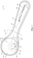
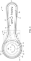
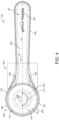
- the figures show different views of an embodiment of the dosing device 100 according to the present invention.
- the dosing device 100 is integrally made of molded pulp fiber.
- the dosing device 100 may be made as a single piece, part or component.
- the dosing device 100 may be a spoon, a measuring spoon or a dosage spoon as exemplarily illustrated in the figures.
- the dosing device 100 may be made from recyclable and/or recycled material. Also, the dosing device 100 may be biodegradable and/or compostable.
- Molded pulp fiber may be made from pulp comprising cellulosic fibrous material that is prepared by chemically and/or mechanically separating cellulose fibers from material containing cellulose fibers.
- the material containing cellulose fibers may be selected from the group consisting of bamboo, sugar cane, sugar beet root, wood, fiber crops, waste paper, and/or rags, or combinations thereof.
- the material containing cellulose fibers may comprise a defined ratio between long fibers and short fibers.
- the material may comprise not less than 20 vol.-% of softwood long fibers, not less than 15 vol.-% of softwood long fibers, or not less than 10 vol.-% of softwood long fibers.
- the remaining fibers may be hardwood fibers, non-wood short fibers, or a combination thereof.
- the pulp used for the dosing device 100 may comprise cellulose, hemicellulose and/or lignin.
- Hemicellulose provides a better adhesion between cellulose nanofibrils, thereby it may contribute to enhanced tensile properties of the dosing device 100.
- the dosing device 100 may be made from pulp with an increased hemicellulose content as experiments pointed towards a higher stiffness and tensile strength for this composition in comparison to pulp with a lower hemicellulose content. Lignin in the pulp has an influence on the texture and flexibility of the dosing device 100.
- the ratio of cellulose, hemicellulose and lignin of the pulp for the dosing device 100 may be configured (adjusted) such that the resulting dosing device 100 has appropriate mechanical properties, such as bending stiffness.
- a ratio of 80:19:1 for cellulose, hemicellulose and lignin may be used.
- the pulp used for the dosing device 100 may further comprise a compound selected from the group consisting of alkyl ketene dimer wax, a fluorine containing polymer moiety, sodium silicate, or combinations thereof.
- Alkyl ketene dimer wax may be used for modifying surface properties of the dosing device 100.
- the use of alkyl ketene dimer wax in the pulp may provide the dosing device 100 with an increased and lasting hydrophobicity.
- a fluorine containing polymer moiety in the pulp may impart to the dosing device 100 an improved resistance to low surface tension fluids, leading for example to an improved grease, oil, wax and solvent repellence.
- the fluorine containing polymer moiety may be a fluorine containing polymer moiety approved for use in contact with food products, for example.
- the fluorine containing polymer moiety may be a copolymer comprising carbon and fluorine moieties, a polymer comprising phosphate and fluorine moieties, or a fluoroalkyl polymer.
- Examples may be selected from the group consisting of perfluoroalkylethylphosphate diethanolamine, ammonium di-[2-(N-ethyl-heptadecafluorosulfonamido)ethyl] phosphate, poly(2-(N-methyl-heptadecafluorosulfonamido)ethyl acrylate)-co-(2,3-epoxypropylacrylate)-co-(2-ethoxyethyIacryIate)-co-(2-(2 -methylpropenyloyloxy)ethyl-trimethylammonium chloride), or combinations thereof.
- a configuration of the pulp used for the dosing device 100 including sodium silicate may lead to increased mechanical strength.
- Sodium silicate may also be used as additive in the pulp during a bleaching process, for example with hydrogen peroxide.
- the dosing device 100 may be produced by pulp molding.
- the dosing device 100 comprises a container portion 200 for receiving and retaining a dosage material.
- the container portion 200 is illustrated in figures 1 to 7 .
- the dosage material may be any powdered or granulated composition to be dosed.
- the dosage material may be a liquid.
- the dosage material may be food.
- the dosage material may be powdered or granulated food, such as nutritional or infant formulas, growing-up milks, milk modifiers, cocoa-based beverage powders, cocoa malt-based beverage powders, coffee, instant food compositions, fruit flavoured beverage powders, spice mixtures, drink thickeners and pet food.
- the term "food” may include any substance, whether processed, semi-processed or raw, which is intended for human consumption. In particular, this may include drinks, chewing gum and any substance, which has been used in the manufacture, preparation or treatment of "food".
- the term "food” does not include cosmetics, tobacco or substances used only as drugs.
- the dosing device 100 may be particularly suitable for food or for dosing food compositions.
- the container portion 200 may have any shape that allows it to take up a certain amount of dosage material.
- the shape of the container portion 200 may be adapted so that it corresponds to a typical shape that resembles the brand of the manufacturer of the dosage material.
- the container portion 200 (or the container body 210) may have a cylindrical, oval, cubic or a cuboidal shape.
- the container portion 200 is exemplarily illustrated as a truncated cone. However, this enumeration is not delimiting but merely an example.
- the container portion 200 may be configured such that it is particularly suitable for scooping movements.
- the container portion 200 may have a material thickness in the range of 300 ⁇ m - 3 mm, 500 ⁇ m - 2 mm, 600 ⁇ m - 1 mm.
- the container portion 200 has a container body 210 that delimits a defined volume 255, in which dosage material can be received and retained.
- the container body 210 has a rim portion 252 that circumferentially delimits an opening 250 at an upper side US of the dosing device 100 to access the defined volume 255.
- Figures 1 and 3 to 7 show the dosing device 100 facing upwards.
- the container body 200 further comprises an outer surface 211. In figures 2 and 5 to 7 , it is exemplarily illustrated that the container body 200 is delimited on its outside by the outer surface 211.
- the outer surface 211 may be a mantle surface (lateral surface) of the container body 210.
- the outer surface 211 may also include the bottom surface 212, which may define the underside of the container portion 200.
- the defined volume 255 may preferably be delimited by the rim portion 252, a bottom portion 253 and an inner lateral surface 251 of the container body 210 extending between the rim portion 252 and the bottom portion 253. This can be seen in figures1 and 3 to 7 .
- the opening 250 in the container body 210 defines an entry for dosage material to pass into a space, i.e. the defined volume 255, inside the container body 210.
- the opening 250 may be a hole in the container body.
- the rim portion 252 may be configured for scooping and/or retaining dosage material.
- the inner lateral surface 251 may extend from the rim portion 252 to the bottom portion 253 in a continuous manner. Thereby, the inner lateral surface 251 may have a constant profile. Alternatively, the inner lateral surface 251 may taper from the rim portion 252 towards the bottom portion 253 as illustrated in figures 1 and 3 to 5 . This arrangement allows to empty the defined volume 255 at the end of the dosing process more easily, thereby increasing the dosing accuracy.
- the dosing device 100 or at least the inner lateral surface 251 may be smooth. Smoothening may be achieved during the manufacturing process. For example, an application of pressure and heat during manufacturing may be used to flatten a surface to be treated.
- the dosing device 100 or at least the inner lateral surface 251 may be resistant against moisture or water uptake. This may be achieved during manufacturing, for example, by pressing and heat application.
- the dosing device 100 or at least the inner lateral surface 251 may comprise a coating, which preferably may be of a biodegradable substance or material.
- the dosing device 100 and/or the inner lateral surface 251 may be coated with a compound or a mixture of compounds, wax, kaolinite, calcium carbonate, bentonite, talc, polyethylene, polyolefin, silicone, and/or biopolymers.
- the defined volume 255 may have any shape or form.
- the defined volume 255 may have a cylindrical, oval, cubic or a cuboidal shape.
- the defined volume 255 is exemplarily illustrated as a truncated cone.
- the shape of the defined volume 255 may correspond with the shape of the container body 210 as exemplarily illustrated in the figures.
- the defined volume 255 may correspond to an amount of dosage material needed for a single consumption occasion or it may correspond to a fraction thereof. Preferably, the defined volume 255 may range from 1 to 20 cm 3 , 2 to 15 cm 3 , 3 to 10 cm 3 , or 8 to 9 cm 3 . However, this enumeration is not delimiting but merely an example.
- the dosing device further comprises a handle portion 300 for manually moving the container portion 200 relatively to the dosage material in a dosing process.
- the handle portion 300 comprises a connecting portion 350, by which the outer surface 211 of the container body 210 is connected to the handle portion 300. This is illustrated in figures 1 to 7 .
- the connecting portion 350 is exemplarily indicated by dashed lines.
- the connecting portion 350 may be adjacent to the rim portion 252 of the container body 210.
- the handle portion 300 extends along a longitudinal axis LA and may have a symmetrical profile when seen from above as illustrated in Figures 1 to 4 .
- the handle portion 300 may taper (laterally from the longitudinal axis LA) from the end of the handle portion 300, which is (most) distant to the container portion 200, towards the connecting portion 350.
- the handle portion 300 may (then) (laterally) widen towards the container portion 200 starting from the connecting portion 350 (along the longitudinal axis LA).
- the handle portion 300 may have a length that is preferential for manual handling or grasping.
- the handle portion 300 may extend along the longitudinal axis LA from 3 to 20 cm, 5 to 15 cm, 5 to 10 cm, or 7 to 8 cm from the connecting portion 350 to the distant end of the handle portion 300.
- the handle portion 300 may have a material thickness in the range of 300 ⁇ m - 5 mm, 500 ⁇ m - 4 mm, or 700 ⁇ m - 3 mm.
- the handle portion 300 of the dosing device 100 may be configured such that its material thickness is higher than the material thickness of the container portion 200. Thereby, manual handling can be improved.
- the handle portion 300 and the container portion 200 may have a material thickness ratio in the range of 1.5:1 to 10:1, 2:1 to 5:1, or 3:1 to 4:1.
- the dosing device 100 may have a length of less than 15 cm, less than 13 cm, less than 11 cm, less than 9 cm, less than 7 cm or less than 5 cm as longest dimension. If the longest dimension is considered the length of the dosing device 100, the width of the dosing device 100 may be less than 5 cm, less than 4 cm, less than 3 cm, less than 2 cm or less than 1 cm.
- the dosing device 100 may have a length of less than 15 cm and a width of less than 4 cm. It may also have a length of less than 15 cm and a width of less than 3 cm. It may also have a length of less than 13 cm and a width of less than 3 cm. It may also have a length of less than 13 cm and a width of less than 2 cm. It may also have a length of less than 11 cm and a width of less than 2 cm.
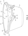
- the rim portion 252 and the handle portion 300 extend in a common plane CP. This is exemplarily illustrated figure 5 . Moreover, the rim portion 252 and the handle portion 300 define a circumferential edge 101 of the dosing device 100. The circumferential edge 101 extends in the common plane CP. With this configuration, it can be achieved that after filling of the container portion 200 any excess dosage material can be scraped off with any appliance having a straight edge, such as a knife, so that as a result the container portion 200 is precisely filled up to the common plane CP.
- the dosing device 100 may extend at its upper side US entirely in the common plane CP.
- the entire top surface of the handle portion 300 and the entire top surface of the container portion 300 may extend in the common plane CP. This is exemplarily illustrated in the figures.
- the dosing device 100 comprises a ribbing portion 400.
- the ribbing portion 400 is illustrated in figures 1 to 7 .
- a different approach to increase the bending stiffness of the dosing device 100 may be, for example, to adjust the composition of the pulp material (details described above) and/or the material thickness of the dosing device 100.
- the present invention it is possible to increase the bending stiffness without having to provide additional or a more sophisticated pulp material.
- the bending stiffness can be determined in accordance with ISO 5628.
- the dosing device 100 may be configured such that it has a bending stiffness in the range of 10 to 80 mNm in a direction along the longitudinal axis LA and/or 5 to 40 mNm in direction transverse thereto.
- the ribbing portion 400 extends from the circumferential edge 101 at least at the handle portion 300 from the common plane CP to a lower side of the dosing device 100 such that mechanical stresses acting on the container body 210 in the dosing process are dissipated by the handle portion 300.
- the dosing device 100 may be stopped by a sidewall of the packaging containing the dosage material and thereby, may be subjected to a bending moment originating from the scooping movement of the hand of the operator. Furthermore, the weight of the dosage material in the container body 210 may cause a bending moment on the dosing device 100.
- the weight of dosage material for powdered food compositions, which is to be scooped into the container body 210 may be in the range of 2 g to 30 g.
- the ribbing portion 400 may protrude from the circumferential edge 101 at the handle portion 300 and at the container portion 200.
- the ribbing portion 400 may protrude (extend) from the circumferential edge 101 at the rim portion 252 as illustrated exemplarily in the figures.
- the ribbing portion 400 may protrude (laterally) from the outer surface 211 of the container body 210.
- the ribbing portion 400 may extend from the circumferential edge 101 at least at the handle portion 300 at opposite sides of the longitudinal axis LA. This is exemplarily illustrated in figures 1 to 4 , 6 and 7 . Thus, the ribbing portion 400 may be provided symmetrically with respect to the longitudinal axis LA. Preferably, the ribbing portion 400 may extend from the entire circumferential edge 101 of the dosing device 100. Therein, the ribbing portion 400 may extend along (and from) the circumferential edge 101 in a continuous manner.
- the ribbing portion 400 may extend at least partially along the circumference of the container portion 200, the connecting portion 350 and the handle portion 300. In particular, the ribbing portion 400 may at least partially extend circumferentially along the rim portion 252. Also, the ribbing portion 400 may extend from the circumferential edge 101 at the rim portion 252. Also, the ribbing portion 400 may be provided or extend laterally from the connecting portion 350 when seen from above. This is exemplarily illustrated in figures 1 to 4 , 6 and 7 .
- the ribbing portion 400 at its (vertical) end opposite to circumferential edge 101 may extend at least partially in a lower side plane LSP that is parallel and offset to the common plane CP.
- the lower side plane LSP may delimit at least a part of the lower side of the dosing device 100 along the handle portion 300 as is shown exemplarily in figures 2 and 5 .
- the ribbing portion 400 may extend from the circumferential edge 101 such that the (entire) ribbing portion 400 may be provided extending away from the common plane CP to the lower side of the dosing device 100.
- the ribbing portion 400 may be at least partially concave towards the upper side US of the container body 210 when seen from above. This can be seen in figures 1 to 7 .
- the ribbing portion 400 may increase at the connecting portion 350 in size in comparison to the remaining parts of the dosing device 100, i.e. the container portion 200 and the rest of the handle portion 300. Thereby, the ribbing portion 400 may increase in a continuous manner and/or with a constant slope. This is illustrated in figures 1 to 7 .
- figure 5 illustrates exemplarily that the ribbing portion 400 may extend at the connecting portion 350 from the circumferential edge 101 to the lower side of the dosing device 100 such that the ribbing portion 400 expands with increasing distance from the rim portion 252.
- the ribbing portion 400 may continuously increase its vertical extension between the common plane CP and its end (vertically) opposite thereto along the longitudinal axis LA (starting from the connecting portion 350).
- the ribbing portion 400 may widen laterally from the longitudinal axis LA at the connecting portion 350 with reducing distance from the rim portion 252. Therein, the ribbing portion 400 may continuously reduce its lateral (horizontal) extension from the circumferential edge 101 at the handle portion 300 along the circumferential edge 101 (and/or the longitudinal axis LA) (starting from the connecting portion 350). This is illustrated exemplarily in figures 1 to 4 , 6 and 7 . Therein, it is illustrated exemplarily that the ribbing portion 400 may extend laterally at the connecting portion 350 such that the ribbing portion 400 transitions onto the rim portion 252 in a continuous manner.
- the ribbing portion 400 may have a L-shaped cross-section when seen along the handle portion 300 (or the circumferential edge 101). However, this is only an example and other shapes of the cross-section of the ribbing portion 400 are conceivable.
- the ribbing portion 400 may have, preferably at least at the connecting portion 350 or at the handle portion 300 or at the dosing device 100, a cross-section that -when seen along the circumferential edge 101- comprises at least two ribbing sections 401-407.
- the ribbing sections 401-407 are exemplarily illustrated in figures 6 and 7 . Therein figure 6 shows ribbing sections 401, 402, 406 and 407 while figure 7 shows ribbing sections 401 to 407.
- the ribbing sections 401-407 may be (external) edges of the ribbing portion 400 that may define the profile and thus, the cross-section of the ribbing portion 400.
- Each of the ribbing sections 401-407 may be a straight edge and/or curved edge.
- Two ribbing sections 401-407 may be distinguishable from each other by their assignment to a corresponding surface of the ribbing portion 400 or by discernible differences (such as steps) in the profile of the ribbing portion 400, for example.
- the ribbing sections 401-407 may extend successively in a row away from the handle portion 300 towards the lower side of the dosing device 100. Moreover, the ribbing sections 401-407 may be tilted with respect to each other and with respect to the common plane CP towards the lower side of the dosing device 100 at a defined slope angle, respectively.
- the number of the ribbing sections 401-407 of at least some of the ribbing sections 401-407 may change at least partially along the circumferential edge 101 of the dosing device 100 or preferably at least at the connecting portion 350.
- This feature becomes apparent by comparing the cross-sections exemplarily illustrated in figure 6 , which shows a cross-section having only four ribbing sections 401-407, with the cross-section illustrated in figure 7 , which comprises seven ribbing sections 401-407.
- the width of at least some of the ribbing sections 401-407 may change at least partially along the circumferential edge 101 of the dosing device 100 (or preferably at least at the connecting portion 350).
- the width may be taken as the (actual) length of the contour of the respective ribbing section 401-407.
- the first ribbing section 401 has a relatively long width in comparison to its width in figure 7 (showing a section of the connection portion 350 in close proximity to the container portion 200).
- the slope angle of at least some of the ribbing sections 401-407 may change at least partially along the circumferential edge 101 of the dosing device 100 (or preferably at least at the connecting portion 350).
- the ribbing section 401 may have at the end of the connecting portion 350 distant to the container portion 200 a relatively steep slope angle (see figure 6 ).
- the ribbing section 401 may have a relatively flat slope angle at the end of the connecting portion 350 close to the container portion 200 (see figure 7 ).
- the changing width of ribbing sections of the at least some ribbing sections 401-407 may (continuously) decrease towards the container portion 200 and/or towards a distal end of the handle portion 300 opposite to the container portion 200.
- ribbing section 406 may have a tapered shape at both of its ends when seen from above.
- the outer edge of the cross-section of the ribbing portion 400 may be formed by the ribbing section 407, which may be substantially perpendicular to the common plane CP and/or tilted away from the circumferential edge 101.
- the cross-section of the ribbing portion 400 at the connecting portion 350 continuously merges into and preferably remains constant along the ribbing portion 400 at the rest of the handle portion 300 and/or the ribbing portion 400 at the container portion 200.
- all figures illustrate that the aforementioned L-shaped cross-section of the ribbing portion 400 may remain constant for the rest of the handle portion 300 and similar can be found for the ribbing portion 400 along the circumference of the rim portion 252.
- the configuration of the cross-section of the ribbing portion 400 as described above may be provided such that the thickness of the ribbing portion 400 evolves from an increased vertical extension towards an increased lateral extension from and along the along the circumferential edge 101 and/or such that the ribbing portion 400 has a corresponding contorted outer surface.
- the ribbing portion 400 may extend from the circumferential edge 101 of the rim portion 252 of the container body 210 such that a space 220 is formed between the ribbing portion 400 and the outer surface 211 of the container body 210.
- the space 220 may be integrally filled. This is exemplarily illustrated in figures 2 and 5 . Space 220 is merely exemplarily indicated in these figures by a groove.
- the handle portion 300 and the corresponding ribbing portion 400 may have a (combined) cross-section with a symmetrical profile.
- the combined cross-section of the handle portion 300 and the corresponding ribbing portion 400 may be mirror symmetrical with respect to a plane that extends with the longitudinal axis and is perpendicular to the common plane CP (see figure 6 ).
- the combined cross-section may be opened towards the lower side of the dosing device 100.
- the combined cross-section may be U-shaped when seen along the longitudinal axis LA. This becomes particularly clear from figures 2 and 5 to 7 .
- the dosing device 100 may be symmetrical with respect to the longitudinal axis LA.
- the dosing device 100 may comprise additional ribbing portions 400 that may be provided on the lower side of the handle portion 300, for example.
- a second aspect of the present invention relates to a method for manufacturing a dosing device 100 as described above.
- the method comprises the following steps:
- the pulp material is dewatered.
- the pulp material may be collected on a grid that has the (negative) shape of the dosing device 100.
- Vacuum suction may be applied.
- the dewatered pulp material is pressed into the form/shape of the dosing device 100.
- a drying step is completed thereafter.
- trimming of the dosing device 100 along external edges defined by the ribbing portion 400 may be completed.
- the method may include additional treatment steps, for example to increase the smoothness or water resistance of the dosing device 100.
- Such steps may comprise the application of heat and pressure.
- a treatment step may include the colouring of the pulp material by adding colours to the pulp material.
- the dosing device 100 may include a further treatment step that includes embossing and/or debossing it for adding a brand name such as decoration elements 510, 520, which are exemplarily illustrated in figures 1 , 3 and 4 . This is not only useful in brand communication, but can also increase the safety of the dosing device 100 by reducing the risk of accidental use for a different purpose.
- an anti-slip surface pattern may be added to the dosing device 100, for example to its handle portion 300.
- a third aspect of the present invention relates to a use of the aforementioned dosing device 100 for dosing a dosage material.
- the dosage material may be from the group consisting of powdered or granulated compositions.
- the dosage material may be food compositions.
- Correct dosing may be ensured by scraping off any excess dosage material from the container portion 200 after filling. Therefore, an appliance with a straight edge, such as a knife, may be used to scrape off any excess material from the filled container portion 200, so the container portion 200 contains exactly the defined volume 255.
Landscapes
- Physics & Mathematics (AREA)
- Fluid Mechanics (AREA)
- General Physics & Mathematics (AREA)
- Engineering & Computer Science (AREA)
- Manufacturing & Machinery (AREA)
- Packages (AREA)
- Paper (AREA)
- Absorbent Articles And Supports Therefor (AREA)
- Making Paper Articles (AREA)
- Food-Manufacturing Devices (AREA)
- Electrical Discharge Machining, Electrochemical Machining, And Combined Machining (AREA)
Claims (15)
- Dosiervorrichtung (100), die aus geformten Zellstofffasern einstückig hergestellt ist, umfassend- einen Behälterabschnitt (200), der ein definiertes Volumen (255) zum Aufnehmen und Zurückhalten eines Dosiermaterials aufweist, wobei der Behälterabschnitt (200) einen Behälterkörper (210) aufweist, der das definierte Volumen (255) abgrenzt, wobei der Behälterkörper (210) einen Randabschnitt (252) aufweist, der eine Öffnung (250) an einer Oberseite (US) der Dosiervorrichtung (100) in Umfangsrichtung abgrenzt, um auf das definierte Volumen (255) zuzugreifen;- einen Griffabschnitt (300) zum manuellen Bewegen des Behälterabschnitts (200) relativ zu dem Dosiermaterial in einem Dosierprozess;wobei der Griffabschnitt (300) durch einen Verbindungsabschnitt (350) des Griffabschnitts (300) mit einer Außenoberfläche (211) des Behälterkörpers (210) verbunden ist und sich von dem Behälterkörper (210) entlang einer Längsachse (LA) erstreckt;wobei sich der Randabschnitt (252) und der Griffabschnitt (300) in einer gemeinsamen Ebene (CP) erstrecken und eine Umfangskante (101) der Dosiervorrichtung (100) definieren, die sich in der gemeinsamen Ebene (CP) erstreckt; und- einen Rippenabschnitt (400), der sich von der Umfangskante (101) mindestens an dem Griffabschnitt (300) bis zu einer Unterseite der Dosiervorrichtung (100) derart erstreckt, dass beim Dosierprozess auf den Behälterkörper (210) wirkende mechanische Spannungen durch den Griffabschnitt (300) abgeleitet werden.
- Dosiervorrichtung (100) nach Anspruch 1, wobei sich der Rippenabschnitt (400) von der Umfangskante (101) mindestens an dem Griffabschnitt (300) auf gegenüberliegenden Seiten der Längsachse (LA) erstreckt, und wobei sich der Rippenabschnitt (400) vorzugsweise von der Umfangskante (101) an dem Randabschnitt (252) und/oder vorzugsweise von der gesamten Umfangskante (101) der Dosiervorrichtung (100) erstreckt, mehr bevorzugt sich durchgehend entlang der Umfangskante (101) erstreckt.
- Dosiervorrichtung (100) nach Anspruch 1 oder 2, wobei sich der Rippenabschnitt (400) an seinem dem Umfangsrand (101) gegenüberliegenden Ende mindestens teilweise in einer Unterseitenebene (LSP) erstreckt, die vorzugsweise versetzt und/oder parallel zu der gemeinsamen Ebene (CP) ist, und wobei vorzugsweise die Unterseitenebene (LSP) mindestens einen Teil der Unterseite der Dosiervorrichtung (100) entlang des Griffabschnitts (300) abgrenzt.
- Dosiervorrichtung (100) nach einem der vorstehenden Ansprüche, wobei der Rippenabschnitt (400) an dem Verbindungsabschnitt (350) in seiner Größe zunimmt, vorzugsweise durchgehend und/oder mit einer konstanten Steigung.
- Dosiervorrichtung (100) nach Anspruch 4, wobei sich der Rippenabschnitt (400) an dem Verbindungsabschnitt (350) von der Umfangskante (101) bis zu der Unterseite der Dosiervorrichtung (100) derart erstreckt, dass sich der Rippenabschnitt (400) mit zunehmender Entfernung von dem Randabschnitt (252) ausdehnt.
- Dosiervorrichtung (100) nach einem der vorstehenden Ansprüche, wobei sich der Rippenabschnitt (400) von der Umfangskante (101) an dem Randabschnitt (252) derart erstreckt, dass ein Raum (220) zwischen dem Rippenabschnitt (400) und dem Behälterkörper (210) gebildet wird, und wobei vorzugsweise der Raum (220) vorzugsweise vollständig ausgefüllt ist.
- Dosiervorrichtung (100) nach einem der vorstehenden Ansprüche, wobei der Rippenabschnitt (400) von oben betrachtet zu der Oberseite (US) des Behälterkörpers (210) hin mindestens teilweise konkav ist.
- Dosiervorrichtung (100) nach einem der vorstehenden Ansprüche, wobei der Rippenabschnitt (400), vorzugsweise mindestens an dem Verbindungsabschnitt (350) oder an dem Griffabschnitt (300) oder an der Dosiervorrichtung (100) entlang der Umfangskante (101) betrachtet einen Querschnitt aufweist, der mindestens zwei, vorzugsweise mindestens drei Rippenabschnitte (401-407) umfasst, die sich in einer Reihe von dem Griffabschnitt (300) weg hintereinander erstrecken und die jeweils in einem definierten Steigungswinkel zueinander und gegenüber der gemeinsamen Ebene (CP) zu der Unterseite der Dosiervorrichtung (100) hin geneigt sind.
- Dosiervorrichtung (100) nach Anspruch 8, wobei sich die Anzahl der Rippenabschnitte (401-407) und/oder die Breite und/oder der Steigungswinkel von mindestens einigen der Rippenabschnitte (401-407) mindestens teilweise entlang der Umfangskante (101) der Dosiervorrichtung (100) ändern, vorzugsweise mindestens an dem Verbindungsabschnitt (350),wobei vorzugsweise die sich ändernde Breite der Rippenabschnitte der mindestens einigen Rippenabschnitte (401-407) zu dem Behälterabschnitt (200) hin und/oder zu einem dem Behälterabschnitt (200) gegenüberliegenden distalen Ende des Griffabschnitts (300) hin abnimmt, vorzugsweise durchgehend abnimmt,wobei vorzugsweise der Querschnitt des Rippenabschnitts (400) an dem Verbindungsabschnitt (350) durchgehend in den Rippenabschnitt (400) an dem restlichen Griffabschnitt (300) und/oder den Rippenabschnitt (400) an dem Behälterabschnitt (200) übergeht und vorzugsweise entlang diesem konstant bleibt.
- Dosiervorrichtung (100) nach einem der vorstehenden Ansprüche, wobei das definierte Volumen (255) durch den Randabschnitt (252), einen Bodenabschnitt (253) und eine sich dazwischen erstreckende innere seitliche Oberfläche (251) des Behälterkörpers (210) abgegrenzt ist, wobei vorzugsweise die innere seitliche Oberfläche (251) sich von dem Randabschnitt (252) bis zu dem Bodenabschnitt (253) durchgehend erstreckt, und/oder wobei vorzugsweise die innere seitliche Oberfläche (251) ein konstantes Profil aufweist oder sich von dem Randabschnitt (252) zu dem Bodenabschnitt (253) hin verjüngt.
- Dosiervorrichtung (100) nach Anspruch 10, wobei die innere seitliche Oberfläche (251) glatt ist und/oder eine Beschichtung umfasst, wobei die Beschichtung vorzugsweise aus einer biologisch abbaubaren Substanz oder einem biologisch abbaubaren Material besteht.
- Dosiervorrichtung (100) nach einem der vorstehenden Ansprüche, wobei der Griffabschnitt (300) und der entsprechende Rippenabschnitt (400) einen Querschnitt mit einem symmetrischen Profil und/oder einen zu der Unterseite der Dosiervorrichtung (100) hin geöffneten Querschnitt, vorzugsweise einen U-förmigen Querschnitt entlang der Längsachse (LA) betrachtet aufweisen.
- Dosiervorrichtung (100) nach einem der vorstehenden Ansprüche, wobei das definierte Volumen (255) in einem Bereich von 1 bis 20 cm3, 2 bis 15 cm3, 3 bis 10 cm3, oder 8 bis 9 cm3 liegt, und/oder
wobei sich der Griffabschnitt (300) von 3 bis 20 cm, 5 bis 15 cm, 5 bis 10 cm oder 7 bis 8 cm von dem Verbindungsabschnitt (350) bis zu einem entfernten Ende des Griffabschnitts (300) erstreckt, vorzugsweise entlang der Längsachse (LA). - Verfahren zum Fertigen einer Dosiervorrichtung (100) nach einem der vorstehenden Ansprüche, umfassend die folgenden Schritte:- Entwässern von Zellstoffmaterial;- Pressen des entwässerten Zellstoffmaterials in die Form der Dosiervorrichtung (100);- Trocknen der gebildeten Dosiervorrichtung (100); und- vorzugsweise Beschneiden der Dosiervorrichtung (100) entlang der durch den Rippenabschnitt (400) definierten Außenkanten.
- Verwendung einer Dosiervorrichtung (100) nach einem der Ansprüche 1 bis 13 zum Dosieren eines Dosiermaterials, wobei das Dosiermaterial aus der Gruppe, bestehend aus pulverförmigen oder granulierten Zusammensetzungen, beispielsweise Lebensmittelzusammensetzungen, stammt.
Priority Applications (1)
| Application Number | Priority Date | Filing Date | Title |
|---|---|---|---|
| EP25175251.5A EP4591763A3 (de) | 2020-03-30 | 2021-03-30 | Dosiervorrichtung |
Applications Claiming Priority (2)
| Application Number | Priority Date | Filing Date | Title |
|---|---|---|---|
| EP20166897 | 2020-03-30 | ||
| PCT/EP2021/058353 WO2021198290A1 (en) | 2020-03-30 | 2021-03-30 | Dosing device |
Related Child Applications (1)
| Application Number | Title | Priority Date | Filing Date |
|---|---|---|---|
| EP25175251.5A Division EP4591763A3 (de) | 2020-03-30 | 2021-03-30 | Dosiervorrichtung |
Publications (2)
| Publication Number | Publication Date |
|---|---|
| EP4127614A1 EP4127614A1 (de) | 2023-02-08 |
| EP4127614B1 true EP4127614B1 (de) | 2025-05-14 |
Family
ID=70108084
Family Applications (2)
| Application Number | Title | Priority Date | Filing Date |
|---|---|---|---|
| EP25175251.5A Pending EP4591763A3 (de) | 2020-03-30 | 2021-03-30 | Dosiervorrichtung |
| EP21716168.6A Active EP4127614B1 (de) | 2020-03-30 | 2021-03-30 | Dosiervorrichtung |
Family Applications Before (1)
| Application Number | Title | Priority Date | Filing Date |
|---|---|---|---|
| EP25175251.5A Pending EP4591763A3 (de) | 2020-03-30 | 2021-03-30 | Dosiervorrichtung |
Country Status (11)
| Country | Link |
|---|---|
| US (2) | US12130164B2 (de) |
| EP (2) | EP4591763A3 (de) |
| CN (1) | CN115362352A (de) |
| AU (1) | AU2021246896A1 (de) |
| DK (1) | DK4127614T3 (de) |
| ES (1) | ES3036206T3 (de) |
| FI (1) | FI4127614T3 (de) |
| MX (1) | MX2022012122A (de) |
| PH (1) | PH12022552397A1 (de) |
| PT (1) | PT4127614T (de) |
| WO (1) | WO2021198290A1 (de) |
Families Citing this family (4)
| Publication number | Priority date | Publication date | Assignee | Title |
|---|---|---|---|---|
| ES2993505T3 (en) * | 2020-01-17 | 2025-01-02 | Nestle Sa | Recyclable dosing device |
| PT4127614T (pt) * | 2020-03-30 | 2025-07-28 | Nestle Sa | Dispositivo de dosagem |
| USD1104783S1 (en) * | 2023-09-19 | 2025-12-09 | Keith Block | Measuring spoon |
| US12169140B1 (en) * | 2024-03-15 | 2024-12-17 | Compostable, LLC | Compostable scoop and method of making same |
Family Cites Families (17)
| Publication number | Priority date | Publication date | Assignee | Title |
|---|---|---|---|---|
| US3013436A (en) * | 1958-11-28 | 1961-12-19 | Mead Johnson & Co | Dispensing measure |
| JPH04343029A (ja) * | 1991-05-20 | 1992-11-30 | Dainippon Printing Co Ltd | 計量スプーン |
| JP3601083B2 (ja) * | 1994-10-07 | 2004-12-15 | 凸版印刷株式会社 | 計量スプーン |
| JPH08176999A (ja) * | 1994-12-26 | 1996-07-09 | Toomoku:Kk | 繊維材料から成るリブ付容器及びその製造方法 |
| JPH09123300A (ja) * | 1995-11-02 | 1997-05-13 | San Chem Kk | 紙製計量具の製造方法 |
| HK1050755A1 (zh) * | 1999-12-30 | 2003-07-04 | The Procter & Gamble Company | 可生物降解的塑料食品供应产品 |
| KR100407287B1 (ko) | 2002-02-19 | 2003-11-28 | 신세환 | 고강도 종이스푼 |
| JP2006189404A (ja) * | 2005-01-07 | 2006-07-20 | Lion Corp | 計量スプーンおよびこれを備えた容器入り洗剤製品 |
| JP4606259B2 (ja) | 2005-06-20 | 2011-01-05 | 花王株式会社 | 計量スプーン |
| JP2009122029A (ja) | 2007-11-16 | 2009-06-04 | Kao Corp | 計量スプーン及び容器入り洗剤 |
| FI125024B (fi) * | 2012-11-22 | 2015-04-30 | Teknologian Tutkimuskeskus Vtt | Muotoiltava kuitutuote ja menetelmä sen valmistamiseksi |
| WO2014109669A1 (ru) * | 2013-01-09 | 2014-07-17 | Polyanskj Vladimir Vasil Vich | Устройство типа ложки для хранения, употребления, внесения и распределения среды функционального питания |
| CN106046824B (zh) * | 2016-05-27 | 2019-04-23 | 赵平国 | 植物纤维制品及其制备方法 |
| CN206964482U (zh) * | 2016-12-08 | 2018-02-06 | 辛阳 | 一次性汤匙 |
| EP3595886B1 (de) * | 2017-03-14 | 2023-09-20 | Geniiq Pte. Ltd. | Tragbares werkzeug |
| US11008142B2 (en) * | 2018-03-02 | 2021-05-18 | Berry Global, Inc. | Lid and scoop for a container |
| PT4127614T (pt) * | 2020-03-30 | 2025-07-28 | Nestle Sa | Dispositivo de dosagem |
-
2021
- 2021-03-30 PT PT217161686T patent/PT4127614T/pt unknown
- 2021-03-30 EP EP25175251.5A patent/EP4591763A3/de active Pending
- 2021-03-30 CN CN202180025964.XA patent/CN115362352A/zh active Pending
- 2021-03-30 WO PCT/EP2021/058353 patent/WO2021198290A1/en not_active Ceased
- 2021-03-30 ES ES21716168T patent/ES3036206T3/es active Active
- 2021-03-30 DK DK21716168.6T patent/DK4127614T3/da active
- 2021-03-30 EP EP21716168.6A patent/EP4127614B1/de active Active
- 2021-03-30 MX MX2022012122A patent/MX2022012122A/es unknown
- 2021-03-30 AU AU2021246896A patent/AU2021246896A1/en active Pending
- 2021-03-30 FI FIEP21716168.6T patent/FI4127614T3/fi active
- 2021-03-30 US US17/907,747 patent/US12130164B2/en active Active
- 2021-04-30 PH PH1/2022/552397A patent/PH12022552397A1/en unknown
-
2024
- 2024-09-26 US US18/897,383 patent/US20250012612A1/en active Pending
Also Published As
| Publication number | Publication date |
|---|---|
| EP4591763A2 (de) | 2025-07-30 |
| EP4591763A3 (de) | 2025-10-08 |
| US12130164B2 (en) | 2024-10-29 |
| MX2022012122A (es) | 2022-10-18 |
| CN115362352A (zh) | 2022-11-18 |
| US20230132527A1 (en) | 2023-05-04 |
| EP4127614A1 (de) | 2023-02-08 |
| WO2021198290A1 (en) | 2021-10-07 |
| AU2021246896A1 (en) | 2022-10-06 |
| FI4127614T3 (fi) | 2025-07-22 |
| DK4127614T3 (da) | 2025-08-04 |
| US20250012612A1 (en) | 2025-01-09 |
| ES3036206T3 (en) | 2025-09-16 |
| PH12022552397A1 (en) | 2023-12-11 |
| PT4127614T (pt) | 2025-07-28 |
Similar Documents
| Publication | Publication Date | Title |
|---|---|---|
| EP4127614B1 (de) | Dosiervorrichtung | |
| JP7284091B2 (ja) | 繊維系食品用容器を製造するための方法および装置 | |
| Deshwal et al. | An overview of paper and paper based food packaging materials: health safety and environmental concerns | |
| US20090057381A1 (en) | Molded paper pulp pizza box | |
| EP3256402B2 (de) | Verpackungseinheit aus geschäumtem geformtem fasermaterial und verfahren zur herstellung einer derartigen verpackungseinheit | |
| WO2007146026A2 (en) | Container wrap | |
| EP2547599B1 (de) | Formteile und verfahren zu deren herstellung | |
| WO2022248232A1 (en) | Container with bottom opening and method of filling such container | |
| US20250102342A1 (en) | Recyclable dosing device | |
| HK40088527A (en) | Dosing device | |
| HK40088527B (en) | Dosing device | |
| CN112793916A (zh) | 一种连体外带披萨盒 | |
| EP4347418B1 (de) | Behälter | |
| RU2837747C1 (ru) | Дозирующее устройство | |
| CN110691741A (zh) | 带涂层的可吸收托盘 | |
| WO2023047295A1 (en) | A cellulose fiber structure for carrying multiple items | |
| RU2852095C1 (ru) | Пригодное для вторичной переработки устройство дозирования | |
| HK40085346A (en) | Recyclable dosing device | |
| HK40085346B (en) | Recyclable dosing device | |
| JP5399842B2 (ja) | 家庭用薄葉紙入り家庭用薄葉紙収納箱 | |
| US12286284B1 (en) | Facial towel packaging box | |
| CN217576116U (zh) | 一种疏水瓶标和饮料瓶 | |
| EP2707223B1 (de) | Material zum verpacken von nahrungsmitteln und verpackung für nahrungsmittel | |
| WO2025120499A1 (en) | A molded three-dimensional packaging product | |
| KR970075108A (ko) | 고지를 이용한 포장용 완충재 제조방법 |
Legal Events
| Date | Code | Title | Description |
|---|---|---|---|
| STAA | Information on the status of an ep patent application or granted ep patent |
Free format text: STATUS: UNKNOWN |
|
| STAA | Information on the status of an ep patent application or granted ep patent |
Free format text: STATUS: THE INTERNATIONAL PUBLICATION HAS BEEN MADE |
|
| PUAI | Public reference made under article 153(3) epc to a published international application that has entered the european phase |
Free format text: ORIGINAL CODE: 0009012 |
|
| STAA | Information on the status of an ep patent application or granted ep patent |
Free format text: STATUS: REQUEST FOR EXAMINATION WAS MADE |
|
| 17P | Request for examination filed |
Effective date: 20221031 |
|
| AK | Designated contracting states |
Kind code of ref document: A1 Designated state(s): AL AT BE BG CH CY CZ DE DK EE ES FI FR GB GR HR HU IE IS IT LI LT LU LV MC MK MT NL NO PL PT RO RS SE SI SK SM TR |
|
| DAV | Request for validation of the european patent (deleted) | ||
| DAX | Request for extension of the european patent (deleted) | ||
| P01 | Opt-out of the competence of the unified patent court (upc) registered |
Effective date: 20230527 |
|
| REG | Reference to a national code |
Ref country code: HK Ref legal event code: DE Ref document number: 40088527 Country of ref document: HK |
|
| GRAP | Despatch of communication of intention to grant a patent |
Free format text: ORIGINAL CODE: EPIDOSNIGR1 |
|
| STAA | Information on the status of an ep patent application or granted ep patent |
Free format text: STATUS: GRANT OF PATENT IS INTENDED |
|
| INTG | Intention to grant announced |
Effective date: 20241211 |
|
| GRAS | Grant fee paid |
Free format text: ORIGINAL CODE: EPIDOSNIGR3 |
|
| GRAA | (expected) grant |
Free format text: ORIGINAL CODE: 0009210 |
|
| STAA | Information on the status of an ep patent application or granted ep patent |
Free format text: STATUS: THE PATENT HAS BEEN GRANTED |
|
| AK | Designated contracting states |
Kind code of ref document: B1 Designated state(s): AL AT BE BG CH CY CZ DE DK EE ES FI FR GB GR HR HU IE IS IT LI LT LU LV MC MK MT NL NO PL PT RO RS SE SI SK SM TR |
|
| REG | Reference to a national code |
Ref country code: GB Ref legal event code: FG4D |
|
| REG | Reference to a national code |
Ref country code: CH Ref legal event code: EP |
|
| REG | Reference to a national code |
Ref country code: DE Ref legal event code: R096 Ref document number: 602021030755 Country of ref document: DE |
|
| REG | Reference to a national code |
Ref country code: IE Ref legal event code: FG4D |
|
| REG | Reference to a national code |
Ref country code: FI Ref legal event code: FGE |
|
| REG | Reference to a national code |
Ref country code: PT Ref legal event code: SC4A Ref document number: 4127614 Country of ref document: PT Date of ref document: 20250728 Kind code of ref document: T Free format text: AVAILABILITY OF NATIONAL TRANSLATION Effective date: 20250722 |
|
| REG | Reference to a national code |
Ref country code: SE Ref legal event code: TRGR |
|
| REG | Reference to a national code |
Ref country code: DK Ref legal event code: T3 Effective date: 20250728 |
|
| REG | Reference to a national code |
Ref country code: NL Ref legal event code: FP |
|
| REG | Reference to a national code |
Ref country code: ES Ref legal event code: FG2A Ref document number: 3036206 Country of ref document: ES Kind code of ref document: T3 Effective date: 20250916 |
|
| REG | Reference to a national code |
Ref country code: LT Ref legal event code: MG9D |
|
| PG25 | Lapsed in a contracting state [announced via postgrant information from national office to epo] |
Ref country code: PL Free format text: LAPSE BECAUSE OF FAILURE TO SUBMIT A TRANSLATION OF THE DESCRIPTION OR TO PAY THE FEE WITHIN THE PRESCRIBED TIME-LIMIT Effective date: 20250514 |
|
| REG | Reference to a national code |
Ref country code: AT Ref legal event code: MK05 Ref document number: 1795119 Country of ref document: AT Kind code of ref document: T Effective date: 20250514 |
|
| PG25 | Lapsed in a contracting state [announced via postgrant information from national office to epo] |
Ref country code: BG Free format text: LAPSE BECAUSE OF FAILURE TO SUBMIT A TRANSLATION OF THE DESCRIPTION OR TO PAY THE FEE WITHIN THE PRESCRIBED TIME-LIMIT Effective date: 20250514 |
|
| PG25 | Lapsed in a contracting state [announced via postgrant information from national office to epo] |
Ref country code: HR Free format text: LAPSE BECAUSE OF FAILURE TO SUBMIT A TRANSLATION OF THE DESCRIPTION OR TO PAY THE FEE WITHIN THE PRESCRIBED TIME-LIMIT Effective date: 20250514 |
|
| PG25 | Lapsed in a contracting state [announced via postgrant information from national office to epo] |
Ref country code: AT Free format text: LAPSE BECAUSE OF FAILURE TO SUBMIT A TRANSLATION OF THE DESCRIPTION OR TO PAY THE FEE WITHIN THE PRESCRIBED TIME-LIMIT Effective date: 20250514 |
|
| PG25 | Lapsed in a contracting state [announced via postgrant information from national office to epo] |
Ref country code: RS Free format text: LAPSE BECAUSE OF FAILURE TO SUBMIT A TRANSLATION OF THE DESCRIPTION OR TO PAY THE FEE WITHIN THE PRESCRIBED TIME-LIMIT Effective date: 20250814 |
|
| PG25 | Lapsed in a contracting state [announced via postgrant information from national office to epo] |
Ref country code: IS Free format text: LAPSE BECAUSE OF FAILURE TO SUBMIT A TRANSLATION OF THE DESCRIPTION OR TO PAY THE FEE WITHIN THE PRESCRIBED TIME-LIMIT Effective date: 20250914 |
|
| PG25 | Lapsed in a contracting state [announced via postgrant information from national office to epo] |
Ref country code: LV Free format text: LAPSE BECAUSE OF FAILURE TO SUBMIT A TRANSLATION OF THE DESCRIPTION OR TO PAY THE FEE WITHIN THE PRESCRIBED TIME-LIMIT Effective date: 20250514 |
|
| PG25 | Lapsed in a contracting state [announced via postgrant information from national office to epo] |
Ref country code: SM Free format text: LAPSE BECAUSE OF FAILURE TO SUBMIT A TRANSLATION OF THE DESCRIPTION OR TO PAY THE FEE WITHIN THE PRESCRIBED TIME-LIMIT Effective date: 20250514 |
|
| PG25 | Lapsed in a contracting state [announced via postgrant information from national office to epo] |
Ref country code: CZ Free format text: LAPSE BECAUSE OF FAILURE TO SUBMIT A TRANSLATION OF THE DESCRIPTION OR TO PAY THE FEE WITHIN THE PRESCRIBED TIME-LIMIT Effective date: 20250514 |
|
| PG25 | Lapsed in a contracting state [announced via postgrant information from national office to epo] |
Ref country code: EE Free format text: LAPSE BECAUSE OF FAILURE TO SUBMIT A TRANSLATION OF THE DESCRIPTION OR TO PAY THE FEE WITHIN THE PRESCRIBED TIME-LIMIT Effective date: 20250514 |
|
| PG25 | Lapsed in a contracting state [announced via postgrant information from national office to epo] |
Ref country code: SK Free format text: LAPSE BECAUSE OF FAILURE TO SUBMIT A TRANSLATION OF THE DESCRIPTION OR TO PAY THE FEE WITHIN THE PRESCRIBED TIME-LIMIT Effective date: 20250514 |
|
| PLBI | Opposition filed |
Free format text: ORIGINAL CODE: 0009260 |