EP3595886B1 - Tragbares werkzeug - Google Patents
Tragbares werkzeug Download PDFInfo
- Publication number
- EP3595886B1 EP3595886B1 EP18768139.0A EP18768139A EP3595886B1 EP 3595886 B1 EP3595886 B1 EP 3595886B1 EP 18768139 A EP18768139 A EP 18768139A EP 3595886 B1 EP3595886 B1 EP 3595886B1
- Authority
- EP
- European Patent Office
- Prior art keywords
- blank
- bending line
- edge
- straight
- bending
- Prior art date
- Legal status (The legal status is an assumption and is not a legal conclusion. Google has not performed a legal analysis and makes no representation as to the accuracy of the status listed.)
- Active
Links
Images


Classifications
-
- B—PERFORMING OPERATIONS; TRANSPORTING
- B31—MAKING ARTICLES OF PAPER, CARDBOARD OR MATERIAL WORKED IN A MANNER ANALOGOUS TO PAPER; WORKING PAPER, CARDBOARD OR MATERIAL WORKED IN A MANNER ANALOGOUS TO PAPER
- B31D—MAKING ARTICLES OF PAPER, CARDBOARD OR MATERIAL WORKED IN A MANNER ANALOGOUS TO PAPER, NOT PROVIDED FOR IN SUBCLASSES B31B OR B31C
- B31D5/00—Multiple-step processes for making three-dimensional articles ; Making three-dimensional articles
- B31D5/04—Multiple-step processes for making three-dimensional articles ; Making three-dimensional articles including folding or pleating, e.g. Chinese lanterns
-
- A—HUMAN NECESSITIES
- A47—FURNITURE; DOMESTIC ARTICLES OR APPLIANCES; COFFEE MILLS; SPICE MILLS; SUCTION CLEANERS IN GENERAL
- A47G—HOUSEHOLD OR TABLE EQUIPMENT
- A47G21/00—Table-ware
-
- A—HUMAN NECESSITIES
- A47—FURNITURE; DOMESTIC ARTICLES OR APPLIANCES; COFFEE MILLS; SPICE MILLS; SUCTION CLEANERS IN GENERAL
- A47G—HOUSEHOLD OR TABLE EQUIPMENT
- A47G21/00—Table-ware
- A47G21/02—Forks; Forks with ejectors; Combined forks and spoons; Salad servers
-
- A—HUMAN NECESSITIES
- A47—FURNITURE; DOMESTIC ARTICLES OR APPLIANCES; COFFEE MILLS; SPICE MILLS; SUCTION CLEANERS IN GENERAL
- A47G—HOUSEHOLD OR TABLE EQUIPMENT
- A47G21/00—Table-ware
- A47G21/04—Spoons; Pastry servers
-
- B—PERFORMING OPERATIONS; TRANSPORTING
- B32—LAYERED PRODUCTS
- B32B—LAYERED PRODUCTS, i.e. PRODUCTS BUILT-UP OF STRATA OF FLAT OR NON-FLAT, e.g. CELLULAR OR HONEYCOMB, FORM
- B32B3/00—Layered products comprising a layer with external or internal discontinuities or unevennesses, or a layer of non-planar shape; Layered products comprising a layer having particular features of form
-
- Y—GENERAL TAGGING OF NEW TECHNOLOGICAL DEVELOPMENTS; GENERAL TAGGING OF CROSS-SECTIONAL TECHNOLOGIES SPANNING OVER SEVERAL SECTIONS OF THE IPC; TECHNICAL SUBJECTS COVERED BY FORMER USPC CROSS-REFERENCE ART COLLECTIONS [XRACs] AND DIGESTS
- Y10—TECHNICAL SUBJECTS COVERED BY FORMER USPC
- Y10T—TECHNICAL SUBJECTS COVERED BY FORMER US CLASSIFICATION
- Y10T428/00—Stock material or miscellaneous articles
- Y10T428/24—Structurally defined web or sheet [e.g., overall dimension, etc.]
- Y10T428/24628—Nonplanar uniform thickness material
Definitions
- the technical field of the present application generally relates to handheld tools, in particular to the forming of handheld tools or utensils from a sheet-shaped blank.
- Handheld tools or utensils made of sheet-shaped materials are used in general as low-cost alternatives to tools made from bulk materials.
- US 20140238987 A1 describes a foldable spoon with a spoon cup section and a spoon handle.
- the spoon handle including apex folds and valley folds, and the spoon cup section are formed from a single sheet of foldable material.
- Singapore Registered Designs 30201703916PY and 30201703915R relate to a fork.
- US 3,828,999 relates to an eating utensil comprising a thin blank having folding lines dividing it into three long areas.
- the object of the present application is to provide an improved user and environment friendly form-stable hand-held tool which can be easily and cost-effectively manufactured.
- the invention is defined by the combination of features of claim 1.
- a blank for forming a handheld tool has a flat, elongated shape.
- the blank can have an essentially symmetric shape, in particular with respect to a longitudinal symmetrical axis.
- a symmetry or symmetrical arrangement refers to a symmetry or symmetrical arrangement with respect to the symmetrical axis of the blank.
- the blank comprises a top surface, a bottom surface opposite to the top surface, a first longitudinal end, a second longitudinal end, a first side end, and a second side end.
- a circumferential cutting edge of the blank comprises a rear edge at the first longitudinal end, a front edge at the second longitudinal end, a first side edge at the first side end and a second side edge at the second side end.
- the blank further comprises at least one essentially continuous upward bending line extending between the side edges of the blank, with a first upward bending segment, a second upward bending segment, and a connecting segment.
- the upward bending segments extend at an oblique angle inwards from respective endpoints at the side edges of the blank, pointing along a longitudinal direction towards the front edge of the blank and providing a vertex with a blunt and at least partially rounded shape.
- a handle section extending from the rear edge to the endpoints of the straight segments of the upward bending lines at the side edges, a functional section extending from the tip of the front edge to the vertex, and an intermediate section between the handle section and the functional section.
- the shape of the functional section may be customized and may significantly vary depending on the specific purpose of the tool and/or intention of the customer.
- the functional section of the blank may have an essentially smooth or rounded contour line for forming spoons or spoon-like tools like scoops, shovels, funnels or similar.
- the functional section may also have a tined contour line for forming forks or forklike tools of various geometries.
- the functional section may further comprise holes or perforations of different number and size for forming strainers or filters out of the blank.
- the blank further comprises a first downward bending line extending between the rear edge and the first upward bending segment, and a second downward bending line extending between the rear edge and the second upward bending segment, as well as a middle area or middle lane extending between the downward bending lines, the upward bending line, and the rear edge.
- the bending lines serve as bending aids which facilitate the bending or folding of the blank in a predetermined manner, facilitating the folding of the blank to form a handheld tool with the desired form.
- an elongated middle lane between the downward bending lines is formed which is free of bending lines.
- the middle lane contributes to the stability of the tool since, in the folded state, the middle lane forms or builds an elongated plateau between the two downwards bent portions of the blank, which serves as a carrying construction and gives a particular stability to the tool.
- the blunt and at least partially rounded shape of the vertex serves for distributing the pressure from the frontal part of the tool over the perimeter of the vertex. This means that the risk of damaging the blank by the compression stress can be reduced. The risk of injuring of persons by the sharp edges at the vertex can be reduced as well.
- the first downward bending line extends between the rear edge and the first side edge and the second downward bending line extends between the rear edge and the second side edge in such a way that two wings at the rear edge of the blank are provided.
- the corner wings at the rear edge of the blank can be used to form a comfortable handle for the handheld tool.
- the downward bending lines may be arranged in such a way that a widening of the middle area at the connecting segment is provided.
- each one of the downward bending lines may comprise an essentially straight longitudinal segment and a curved segment, the curved segments forming the widening of the middle area or middle lane.
- the longitudinal arrangement of the straight segments of the downward bending lines in the region between the rear edge of the blank and the vertex provides a particularly good protection for this region which can serve as a carrying construction or spine of the tool.
- the straight segments of the downward bending lines may extend to the rear edge of the blank. Extending the straight segments of the downward bending lines to the rear edge of the blank facilitates an accurate folding along the downward folding lines, especially in the region of the rear edge.
- one or more indentations in the rear edge can be provided.
- the indentations at the end of the downwards bending lines can substantially facilitate the bending of the blank at the rear edge.
- the widening of the vertex can serve for local stress reduction in the vertex region and thus result in a more stable tool.
- the angle between the first upward bending segment and the second upward bending segment may be chosen in a range of 20° to 66°, more specifically of 26° to 35°.
- Each one of the downward bending lines may meet the upward bending line at a respective junction point adjacent to the vertex.
- the forming of the tool out of the blank can be facilitated by improving the controlled foldability in the vertex area.
- the angle between the upward bending line and the respective downward bending line may be essentially perpendicular or lie in the range of 60° to 90°, more specifically of 80° to 90°. Due to choosing or predefining the angle between the upward bending line and the respective downward bending line at the junction points, building of folds with sharp angles can be avoided, and the controllable foldability of the blank in the vertex region can be improved.
- the blunt and at least partially rounded vertex may have an essentially smooth shape.
- the vertex may have a circular shape or a flat tip with rounded corners.
- the smooth shape of the vertex can smoothen the tension distribution in the blank such that local stress maxima in the vertex region can be reduced.
- At least one of the bending lines may be provided by an essentially continuous bending groove formed on at least one surface of the blank.
- the groove may be scored or coined in the respective surface of the blank.
- the grooves may also be formed by application of pressure, cutting, by laser ablation, or similar.
- the bending lines desired pattern can be easily provided.
- the groove may be provided on the top surface of the blank.
- the blank By providing the groove on the top surface of the blank, the blank can be weakened along the bending lines in such a way that the blank is particularly easily bendable or foldable downwards along the bending line.
- the groove can be provided on the bottom surface of the blank.
- the blank By providing the groove on the bottom surface of the blank, the blank can be weakened along the bending lines in such way that the blank is particularly easily bendable or foldable upwards along the bending line.
- the groove for the bending lines may have a rounded or essentially rectangular profile with an aspect ratio, i.e. the ratio of its depth to the width between 1 and 5, more specifically between 2 and 4.
- the depth of the score may be in the range of 10 to 30 per cent of the thickness of the blank, depending on the chosen materials.
- At least one of the bending lines may be also formed by providing, in particular by printing, an additional material layer along the predefined paths of the bending lines.
- additional material layer which in general can have mechanical characteristics different from those of the basic material of the blank, the bendability of the blank can be locally modified in such way that the blank is more easily bendable in one direction than in another direction thus facilitating the bending or folding of the blank.
- the profile and the exact dimensions of the groove depends in general on the chosen material, on the thickness, and on the purpose of the blank.
- the blank may comprise compostable and/or recyclable materials, in particular approved or certified by the Food and Drug Administration (FDA), Sustainable Forestry Initiative (SFI),
- the blank material can also comprise FRP (Fibreglass Reinforced Plastic), microlattice, Dyneema, Polypropylene (PP), High-Density Polyethylene (HDPE), Low-Density Polyethylene (LDPE), Polycarbonate (PC), nano-tubes to name but a few.
- FRP Fiberglass Reinforced Plastic
- microlattice Dyneema
- Polypropylene PP
- High-Density Polyethylene HDPE
- LDPE Low-Density Polyethylene
- PC Polycarbonate
- the material can have a material area density in the range from 230 g/m2 to 350 g/m2.
- the orientation of the paper grains can be chosen essentially parallel to the longitudinal direction of the blank.
- elevated portions or bumps of essentially round and/or elongated shapes can be provided.
- the robustness of the tool can be improved. Furthermore, by providing the bumps or elevated portions in the handle section of the blank, the grip of the handle of the tool can be improved, such that the tool can be securely grasped.
- the blank may have an essentially tapered shape, such that the width of the blank at the rear edge is smaller than the width of the functional section.
- the side edges can comprise essentially straight segments being arranged under an oblique angle with respect to the symmetrical axis in such way that the width of the blank at the rear edge is smaller than the maximum width of the functional section, in particular between the tip of the front edge and the vertex.
- Such a tapered form of the blank results in general in a tool with a narrower handle and a wider functional section.
- the tapered form may be used to save material during the manufacturing of the blank.
- cutting the blanks with alternating orientation can lead to substantial material savings in the case of tapered shape of the blank.
- additional bending lines are provided, essentially parallel to the bending lines.
- additional downward bending lines can extend in parallel to the symmetrical axis in the region of the middle lane.
- the bending may be shared over the plurality of the downward bending lines in such way that the bending angle at each of the bending line, and thus the stress of the blank, is reduced.
- a blank with an essentially flat, elongated shape for folding to form a handheld tool comprises two bendable side wings, in particular in a handle section of the blank, a middle lane or middle lane region arranged along a longitudinal symmetrical axis of the blank, and a bow which partially circumvents one end of the middle lane.
- the bow can in particular at least partially comprise a function section or functional part of the tool which is to be formed.
- the side wings and the middle lane are at least partially demarcated by downward bending lines, and the bow is demarcated from the middle lane and from the side wings by an upward bending line is such way that between the middle lane and the bow a vertex of the upward bending lines is formed.
- a bending of the side wings from the plane of the blank, in particular with respect to the middle lane, then results in a tensile stress along the circumference of the bow and in a compression stress in the vertex region of the bow.
- a middle channel or spine is formed from the middle lane or middle lane region in the course of bending of the side wings of the blank.
- the plane geometry of the bow is energetically not favourable, such that a mechanical fluctuation, such as a manual tilting of the tip of the bow in one or another direction from the initial plane can lead to at least partial release of the stress, thus leading to a stable three-dimensional shape of the tool.
- the blank may comprise a rear edge and a tip
- the middle lane can extend in the region between the rear edge and the vertex, reaching the rear edge and/or the vertex.
- the upward bending line may comprise two upward bending segments connecting endpoints at the side edges of the blank with the vertex.
- the upward bending segments can be formed as essentially symmetrically arranged and essentially continuous straight segments.
- the endpoints at the side edges are moved or dragged with the side wings. This means that the endpoints leave the plane of the blank, in particular that of the middle lane, and move essentially in a plane perpendicular to the symmetrical axis of the blank, causing a deformation of the bow.
- the endpoints can be useful to see whether the side wings are bent correctly by checking whether, in the state of the formed tool, the endpoints meet.
- the vertex can have a smooth, at least partially rounded or piecewise rounded shape. Due to such a shape of the vertex, local tensions in the blank material as well as the risk of injuring of the user can be reduced.
- the middle lane can have a widening at an end proximal to the vertex.
- the middle lane By widening the middle lane at the vertex, the middle lane provides a wide support for the vertex to withstand the compression stress from the side of the bow.
- the pressure from the frontal part of the bow is distributed over the perimeter of the vertex in such way that the risk of damaging the blank by the compression stress in the vicinity of the vertex is reduced.
- the blank especially the side wings of the blank, may be equipped with magnets.
- stripes of magnetic material can be laminated on or embedded in the side wings of blank.
- the magnets in the side wings can keep the side wings together or in a folded state even if the tool is not actually in use and hence no bending force is applied by the user.
- a process for manufacturing a blank for forming a handheld tool comprises providing a flat sheet of workpiece of worksheet.
- any material can be used which is suitable for the manufacturing process according to the aspect, and which is in particular suitable for usage according to any purpose of the tool which is to be formed out of the blank.
- the worksheet can in particular be paper-based, silicone-based, metal-based, or similar.
- the worksheet can comprise compostable and/or recyclable FDA-approved food-safe materials, including but not limited to paper, especially with an area density in the range from 230 g/m2 to 350 g/m2.
- the process further comprises providing bending aids in the form of downward bending lines and in the form of at least one upward bending line at predefined positions of the workpiece of the workpiece, as well as cutting the workpiece according to a predefined pattern in such way that a blank of essentially symmetric elongated shape is cut out.
- a die-cutting processes For cutting out of the blank out of the workpiece, a die-cutting processes may be used.
- the die-cutting process is especially suitable for cutting many pieces of the same shape by using die-cutting tools.
- the bending lines may be formed by providing surface grooves by scoring or coining of the worksheet.
- laser cutting may be used. By using the laser cutting, the cutting pattern can be easily adjusted or modified.
- the workpiece may comprise paper with a grain-orientation which is essentially parallel to the longitudinal axis of the blanks.
- the process may further comprise formation of elevated portions in the blank.
- the elevated portions or bumps can serve for additional robustness of the handheld tool and can also improve the grip for grasping and holding by the user.
- the bumps can be coined or blind embossed in the blank. Thus, the bumps can be easily formed.
- the process may further comprise providing a reinforcement in the form of one or more reinforcement layers of the blank.
- the reinforcement layer can comprise silicon, metal or plastic provided at critical areas of the blank which are exposed to the stress during forming or usage of the tool.
- the reinforcement may comprise an embedded layer, i.e. a material layer which is embedded in the worksheet material.
- the reinforcement layer may comprise a moulded, in particular an extrusion-moulded, silicone layer.
- the reinforcement may comprise one or more embossed structures, similar to those of the bumps formed in the blank.
- the process may further comprise providing colour marking of the blank.
- the colour marking can be used for marking the folding lines as well as the functional sections for ease of usage.
- the process may be carried out as a batch process in which two or more blanks are produced out of one workpiece.
- the blanks may be produced from the workpiece in such an arrangement that the blanks are parallel to each other while adjacent blanks are oriented in opposite directions.
- a handheld tool which is formed by folding the blank according to the first aspect.
- the particular shape and dimensions may vary depending on the specific design and purpose of the tool, as well as on the chosen materials.
- reverse spoons By changing the bending direction of the functional part, “reverse spoons” may be formed which can be used as a funnel or utensil for soft-foods such as yogurt, sorbet, soya bean curd to name but a few.
- Such reversed tools are also characterized by robustness and form-stability, since an energetically favourable stable configuration can also be achieved when the front portion of the functional section is bent in the same direction with respect to the plan of the middle lane as the side wings.
- the application provides a blank for forming a handheld tool.
- the blank can be folded to form a desired handheld tool.
- the handheld tool is a cup.
- the cup can also refer to a bowl, a container, or a scoop.
- the blank includes a flat and elongated sheet.
- the flat and elongated sheet comprises two opposing major surfaces, namely a top surface with a bottom surface.
- the sheet also includes a first longitudinal end and a second longitudinal end as well as a first side end and a second side end.
- the first longitudinal end is located opposite to the second longitudinal end.
- the first side end is located opposite to the second side end.
- the sheet also comprises a circumferential edge.
- the circumferential edge comprises a rear edge being provided at the first longitudinal end, a front edge being provided at the second longitudinal end, a first side edge being provided at the first side end, and a second side edge being provided at the second side end.
- the flat and elongated sheet includes a partial stadium-shaped portion.
- the partial stadium-shaped portion comprises a circular upward bending line, a first straight downward bending line, and a second straight downward bending line.
- a first end of the circular upward bending line is placed to next a first end of the first straight downward bending line while a second end of the circular upward bending line is placed to next to a first end of the second straight downward bending line.
- a second end of the first straight downward bending line is placed next to a second end of the second straight downward bending line.
- this arrangement of the circular upward bending line, the first straight downward bending line, and the second downward straight bending line allow the partial stadium-shaped portion to bend for forming a container portion of a cup of the handheld tool.
- the container portion has a cone portion.
- the circular bending line provides the cone portion with a blunt vertex.
- the blunt vertex acts to increase durability of the container and it does not cut a user of the container portion of the handheld tool.
- the flat and elongated sheet often include a rectangular portion.
- the rectangular portion comprises at least one longitudinal downward bending line, at least one lateral upward bending line with at least one corresponding lateral downward bending line.
- the longitudinal downward bending line, the lateral upward bending line, and the lateral downward bending line are often straight.
- the longitudinal downward bending line extends or stretches from the rear edge towards the direction of the front edge.
- the lateral upward bending line extends from the longitudinal downward bending line to the first side edge while the lateral downward bending line extends from the longitudinal downward bending line to the second side edge.
- the lateral upward bending line is also aligned to the corresponding lateral downward bending line.
- the longitudinal downward bending line, the lateral upward bending line, and the lateral downward bending line are arrangement such that they allow the rectangular portion to bend, wherein the rectangular portion bends to form a handle portion of the handheld tool.
- the upward bending line often includes a scored line that is provided on the bottom surface of the blank.
- the scored line refers to a narrow hollow channel, to a bending groove, or to a narrow elongated depressed area for facilitating bending or folding of the blank to form a desired handheld tool.
- the depth and the width of the scored line are often adapted according to material, to thickness, and to purpose of the blank.
- the downward bending line can include a scored line that is provided on the top surface.
- the rectangular portion can include one or more pairs of flap part die cut lines. These cut lines allow parts of the blank to bend. In use, the parts are bent such that these parts act as flap parts to support a side part of the container portion.
- the rectangular portion further comprising just one pair of cut lines.
- the rectangular portion includes two pairs of cut lines.
- the straight longitudinal downward bending line can include one straight longitudinal downward bending line segment. This is often provided for a blank that is thin.
- the straight longitudinal downward bending line can also include two straight longitudinal downward bending line segments, which are provided close to each other. This is often provided for a blank that is thick. The dual bending line segments allow the thick blank to bend easily.
- the straight lateral upward bending line can include just one straight lateral upward bending line segment while the straight lateral downward bending line include just one corresponding straight lateral downward bending line segment.
- the straight lateral upward bending line can include two straight lateral upward bending line segments while the straight lateral downward bending line include two corresponding straight lateral downward bending line segments.
- the two-straight lateral upward bending line segments are provided close to each other while the two-corresponding straight lateral downward bending line segments are also provided close to each other. This arrangement is often provided for a thick blank, wherein these line segments allow the thick blank to bend easily.
- the two-straight lateral upward bending line segments are provided far from each other while the two-corresponding straight lateral downward bending line segments are also provided far from each other. This arrangement allows an elongated part of the blank to bend at two parts of the blank for forming the handle portion of the blank.
- the blank can include an indentation that is provided at an intersection between the straight lateral upward bending line and the corresponding straight lateral downward bending line.
- the indentation acts to contain material thickness of the blank. When the blank is bent, the bent area often enlarges, especially in corners. This enlarging can deter the bending of the blank.
- the indentation serves to receive the enlarged area to allow for easier bending of the blank.
- the indentation often has a trapezoid shape which is effective for receiving the above described enlarged area of the blank.
- the blank often includes a first straight upward bending line segment and a second straight upward bending line segment.
- the first straight upward bending line segment extends from the circular upward bending line to the first side edge.
- the second straight upward bending line segment extends from the circular upward bending line towards the direction of the second side edge.
- the first straight upward bending line segment and the second straight upward bending line segment allow easier bending of the partial stadium-shaped portion for forming the container portion of the handheld tool.
- the blank can include silicon material or a food-grade paper material, although other materials are also possible.
- the application provides a handheld tool that is formed by folding the above described blank.
- the application provides a moulded blank for forming a handheld tool, namely a spoon or spade.
- the moulded blank includes two generally flat portions which are separated by a predetermined distance.
- the moulded blank is shaped or formed by a process using pressure.
- the process can include a heating and/or drying step.
- An example of the process is pulp moulding.
- the moulded blank includes an elongated sheet.
- the elongated sheet includes a top surface and a bottom surface being provided opposite the top surface.
- the sheet also includes a first longitudinal end and a second longitudinal end being provided opposite the first longitudinal end, a first side end and a second side end being provided opposite the first side end.
- the elongated sheet also includes a circumferential edge that comprises a rear edge being provided at the first longitudinal end, a front edge being provided at the second longitudinal end, a first side edge being provided at the first side end, and a second side edge being provided at the second side end.
- the elongated sheet also includes a bending cum connecting strip extending between the two opposing side edges of the blank.
- the bending cum connecting strip including a first strip segment, a second strip segment, and a connecting strip segment.
- the first strip segment and the second strip segment extend at an oblique angle inwards from respective endpoints at the side edges of the blank, pointing along a longitudinal direction towards the front edge of the blank.
- the connecting strip segment serving as a blunt vertex, which has at least partially rounded shape.
- the elongated sheet also includes a first downward bending line extending between the rear edge and the first strip segment and a second downward bending line extending between the rear edge and the second strip segment.
- the bending cum connecting strip and the front edge enclose a first generally flat portion while the bending cum connecting strip and the rear edge enclose a second generally flat portion.
- the first flat portion is provided in a first plane, while the second generally flat portion is provided in a second plane.
- the second plane is separated from the first plane by a predetermined distance.
- This separation allows for easier folding of the blank to form a tool.
- the separation allows the user to bend the bank for forming a spoon in one movement by just pressing the sides of the bank toward each other.
- the application provides a further moulded blank for forming a handheld tool, namely a spoon or spade.
- the moulded blank includes two generally flat portions. One flat portion is bent to serve as a container portion and the other flat portion is bent to serve as a handle portion of a spoon.
- the moulded blank includes an elongated sheet.
- the elongated sheet includes a top surface and a bottom surface being provided opposite the top surface.
- the sheet also includes a first longitudinal end and a second longitudinal end being provided opposite the first longitudinal end, a first side end and a second side end being provided opposite the first side end.
- the elongated sheet also includes a circumferential edge that comprises a rear edge being provided at the first longitudinal end, a front edge being provided at the second longitudinal end, a first side edge being provided at the first side end, and a second side edge being provided at the second side end.
- the elongated sheet also includes a bending cum connecting strip extending between the two opposing side edges of the blank.
- the bending cum connecting strip including a first strip segment, a second strip segment, and a connecting strip segment.
- the first strip segment and the second strip segment extend at an oblique angle inwards from respective endpoints at the side edges of the blank, pointing along a longitudinal direction towards the front edge of the blank.
- the connecting strip segment serving as a blunt vertex, which has at least partially rounded shape.
- the elongated sheet also includes a first downward bending line extending between the rear edge and the first strip segment and a second downward bending line extending between the rear edge and the second strip segment.
- the bending cum connecting strip and the front edge enclose a first generally flat portion while the bending cum connecting strip and the rear edge enclose a second generally flat portion.
- the first flat portion is bent to serve as a container portion and the second flat portion is bent to serve as a handle portion of a spoon.
- the shape of the moulded blank allows for easier folding of the blank to form a tool.
- the shape allows the user to bend the bank for forming a spoon in one movement by just pressing the sides of the bank toward each other.
- the blank can include one or more other features described above.
- Some parts of the embodiments have similar parts.
- the similar parts may have the same names or similar part numbers with an alphabet symbol or prime symbol.
- the description of one part applies by reference to another similar part, where appropriate, thereby reducing repetition of text without limiting the disclosure.
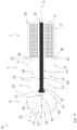
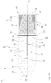
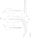
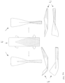
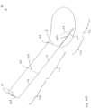
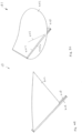
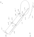
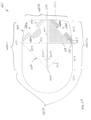
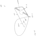
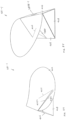
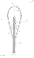
- Figs. 1 and 2 show a blank 1, which is intended for folding to form a handheld tool according to an embodiment.
- the blank 1 is intended for folding to form a handheld tool and it has a flat, elongated, and essentially symmetric shape, its symmetrical axis A being indicated as a dash-dotted line in the figure.
- the blank 1 comprises a top surface 2, a bottom surface 3 opposite to the top surface 2, a first side edge 4, a second side edge 4' opposite to the first side edge 4, a front edge 5, and a rear edge 6.
- the blank 1 essentially comprises three sections - a handle section 7, a functional section 8, as well as an intermediate section 9 which connects the handle section 7 with the functional section 8.
- the blank 1 also comprises a bending aid in the form of downward bending lines 10, 10' and an upward bending line 11 for facilitating bending or folding of the blank 1 in a predefined manner for forming the handheld tool with the desired form.
- the upward bending line 11 which is shown as a dashed line has a shape of a smooth continuous line extending between two opposite edges 4, 4' of the blank and comprising two essentially straight upward bending segments 12, 12'.
- Each one of the straight upward bending segments extends from a respective side edge 4, 4' at the handle section 7 of the blank 1 over the intermediate section 9 towards the functional section 8 under an oblique angle with respect to the symmetrical axis A of the blank 1 such that the both upward bending segments 12, 12' are connected over a middle or connecting segment 13 forming a blunt vertex at the functional segment 8 of the blank 1.
- the shape of the vertex 13 may be different.
- the vertex has an essentially circular shape with a curvature radius of approximately 5 mm.
- the downward bending lines 10 comprise two symmetrically arranged smooth continuous lines which are shown as solid lines, each comprising a straight segment 14, 14', extending from the rear edge 6 of the blank 1 towards the vertex 13, and a curved portion 15, each one of the curved portion 15 of the downward bending lines 10 ending at a respective junction point 16 at the upward bending line 11 in the vicinity of the vertex 13.
- the straight segments 14, 14' of the downward bending line 10 are extending longitudinally on both sides and close to the symmetrical axis A, such that a stripe extending from the rear edge 6 to the vertex 13 is formed.
- the straight portions 15 are parallel to each other and to the symmetrical axis A of the blank 1.
- the central stripe or middle channel has an essentially constant width over its whole length, except in the vertex region, in which the middle channel widens due to the curved portions 15 of the downward bending lines 10.
- the upward bending line 11 lie essentially perpendicular to the downward bending line 10.
- the angle between the upward bending line 11 and the downward bending line 10 at the junction point 16 is between 60° and 90°, more specifically between 80° and 90°.
- the upward bending segments 12, 12' of the upward bending line 11 form or build an angle of approximately 26°.
- the length of the tool is approximately 130 mm while its width is about 40 mm.
- the handle section 7, the intermediate section 9, and the functional section have lengths of approximately 40 mm, 63 mm, and 27 mm, respectively.
- the angle between the upward bending segments 12, 12' of the upward bending line 11 may vary, in particular, from approximately 20° up to approximately 66°.
- the vertex 13 of the upward bending line 11 and the curved portions 15 of the downward bending line 10 show a circular curvature with approximately the same curvature radius as the vertex 13.
- the curvature radius in this embodiment is approximately 5 mm.
- indentations 18 are provided in the rear edge 6 of the blank 1.
- the rear edge 6 is essentially straight and has rounded corners 19.
- the radius of curvature of the rounded corners is approximately 2 mm.
- the side edges 4 of the blank 1 are straight and slightly inclined with respect to the symmetrical axis A of the blank in such a way that the width of the blank 1 at the rear edge 6 is smaller than the width of the functional section 8 of the blank 1.
- the front edge 5 has a circular shape with a curve diameter equal to the width of the functional section 8.
- the depth of the indentations 18 in the rear edge are approximately 2 mm.
- the length of the blank 1 is approximately 130 mm and the maximum width is 40 mm.
- elongated transversal structures 20 are provided in the handle section 7 adjacent to the intermediate section 9 .
- the transversal structures 20 are provided in a shape of elongated bumps lying perpendicular to the symmetrical axis A of the blank 1.
- the bending lines 10, 10', 11 are formed as bending grooves scored in a surface of the blank.
- the bending groove is provided on the top surface 2 of the blank 1.
- the bending groove is provided on the bottom surface 3 of the blank 1.
- the bumps and/or the bending aids may be provided with colour marks in order to facilitate the recognition of the handle section and/or the bending aids.
- the blank 1 is a blank for a disposable spoon made from paper which is approved by the Food and Drug Administration (FDA).
- the area density of the paper is approximately 300 g/m 2 .
- various materials may be used, such as paper, cardboard, metal, silicone, or any other suitable material.
- the blank may comprise compostable and/or recyclable FDA-approved food-safe materials, including but not limited to paper, especially with an area density in the range from about 200 g/m 2 to about 350 g/m 2 .
- the depth and the width of the bending scores depends in general on the material, thickness, and the purpose of the blank.
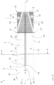
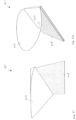
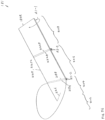
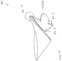
- the blank 1 can be easily shaped into a handheld tool by manually bending it along the bending lines 10 and 11.
- the bending lines 10, 10' and 11 demarcate four separate areas of the blank 1, including two side wings 30 arranged symmetrically with respect to the symmetrical axis A of the blank 1, a middle lane 31 corresponding to the central channel along the symmetrical axis A, and a bow 32 which includes the functional section 8 and extends over the intermediate section 9 and partially circumvents the vertex 13.
- the side wings 30 extend from the rear edge 6 of the blank 1 over the handle section 7 and the intermediate section 9 to the vertex 13.
- the side wings 30 and the bow meet at respective endpoints 21, 21' which are endpoints of the upward bending line 11.
- the downward bending lines 10 demarcate the border between the side wings 30 and the middle lane 31.
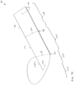
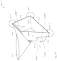
- the side wings 30 of the blank 1 are bent downwards (away from the viewer) with respect to the middle lane 31.
- the downward movement of the side wings 30 is indicated by downward movement arrow symbols 33.
- the longitudinal dimensions of the blank remain essentially the same and the endpoints 21, 21' move essentially perpendicular to the symmetrical axis A of the blank 1 or to the middle lane 31.
- the tensile stress along the circumference of the bow 32 is shown as bended arrows 40.
- the endpoints 21, 21' at the side edges 4 are also moved or dragged down.
- the bow 32 ceases to be a plane or essentially two-dimensional object and it becomes a three-dimensional object instead.
- the middle lane 31 With the formation of side brinks along the upward bending line 11, the middle lane 31 provides a form-stable carrier construction of the tool. If the tool is provided as a spoon, in use, the middle lane 31 together with the side brinks acts to prevent cutting of mouth or lips of the user.
- the frontal part of the bow 32 can flip upwards and can take a stable position, in which the circumferential tension along the tension lines 40 is minimized.
- the upward movement of the front part of the bow 32 is shown by an upward movement arrow symbol 34.
- the functional section 8 obtains a cup shape, the vertex 13 being the deepest point of the cup, and the blank 1 becomes a form-stable tool which in this embodiment is a small spoon.
- the bumps 17 and the transversal structures 20 can serve as grip structures or grippers for easier handling of the tool by the user.
- the blank of Fig. 1 can be easily manufactured. Firstly, a flat worksheet or workpiece comprising paper, cardboard, plastic, metal or any suitable material is provided.
- the bending lines may be scored or coined in the blank sheet of the blank material at predefined positions in correspondence with the specific embodiment of the blank.
- the bumps 17 and the transversal structures 20 may be embossed or coined, by pressing the worksheet between two complementary tools of appropriate shape.
- the bumps and/or the transversal structures are blind-embossed in the worksheet.
- the blank 1 is cut out of the worksheet, in particular by means of die-cutting.
- the formation of the bending lines 10, 11, bumps 17, transversal structures 20, and/or die cutting can be performed on a bigger area of a worksheet in such way that more than one blank out of a single panel is produced. Such a batch or bulk production can save time and costs in the manufacturing process.
- a rolling machine in particular a die-cutting roller, may be used for carrying out at least one of the previously mentioned operations.
- one or more reinforcement layers are provided, in particular of the middle lane 31.
- the reinforcement may be formed as an additional material layer provided along the middle lane.
- the additional material layer may comprise metal, thermoplastic or thermoset material. It may be laminated, especially glued, onto the on the top surface 2 or on the bottom surface 3 of the blank 1. In some embodiments, reinforcement is embedded in the blank 1.
- the reinforcement may comprise fibers embedded in the blank material or applied on one of the surfaces of the blank material.
- the blank 1 of Fig. 1 include a bending line or a die cut line such that the unfolded or flat blank 1 can act as a bookmark. Advertisement or useful information can also be printed on the blank 1, thereby allowing a user of the blank 1 to have quick and easy access to such data.
- Fig. 3 shows a schematic top view of a blank 1a for folding to form a handheld tool according to another embodiment.
- the blank 1a of Fig. 3 in its structural and functional parts, essentially corresponds to the embodiment of Fig. 1 .
- Fig. 1 One difference to the embodiment of Fig. 1 lies in the specific shape of the blank 1a, in particular in the shape of the vertex 13 and of the tip 22. Further, different to Fig. 1 , the straight segments 14 of the downward bending lines 10 are not parallel, but meet at a single indentation 18 at the rear edge 6 of the blank 1a.
- the middle lane 31 narrows towards the rear edge 6 turning essentially into a single line at the rear edge 6.
- the vertex 13 has a flat tip and rounded corners.
- the junction points 16 between the downward bending lines 10 and the upward bending line 11 lie slightly apart from the rounded corners of the vertex on the straight segments 12 of the upward bending line 11.
- the angle between the straight segments 12 of the upward bending line 11 is approximately 22 degrees.
- the blank 1a also comprises the transversal structure 20 and the bumps 17.
- the bumps 17 in this embodiment are elongated and transversally oriented.
- the bumps 17 and the transversal structures 20 are coloured in order to designate the handle section for ease of use.
- the particular shape of the blank 1a is attributable to the particular shape of the handheld tool which is to be formed out of the blank 1a.
- the tool formed out of the blank 1a of Fig. 3 is supposed to have a broad flat tip making it suitable for such tasks as scooping or shoveling.
- the broad flat shape of the vertex allows for forming a cup that is shallow and broad.
- the broad flat shape may also be helpful to reduce the compression stress at the vertex and also to obtain the desired three-dimensional shape of the functional section of the tool.
- the narrowing of the middle lane 31 towards the rear edge 6 may be useful for saving material during mass production of the tool.
- more blanks 1a can be accommodated side by side on the same area by placing them in alternating orientation, and hence more blanks can be produced out of a single workpiece.
- the weakening of the plateau or central carrying construction by the narrowing of the main lane 31 at the rear edge does not significantly deteriorate the overall stability of the tool, since the main tensions are distributed over the intermediate section 9 and the functional section 8, with a maximum of compression stress in the region of the vertex 13.
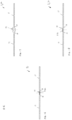
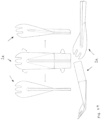
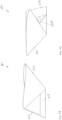
- Figs. 4 and 5 show a blank 1b.
- the blank 1b is intended for folding to form a handheld tool according to a further embodiment.
- the blank 1b of Fig. 3 has two additional downward folding lines 10a and 10a' in the form of straight lines parallel to the symmetrical axis A of the blank 1b.
- Each of the additional folding lines 10a and 10a' extend from a respective junction point 16 at the vertex 13 to a respective indentation 18 at the rear edge 6 of the blank 1b.
- the additional folding lines 10a and 10a' act to provide a stronger middle lane 31.
- the vertex 13 is slightly narrower as compared to the embodiment of Fig. 1 .
- the angle between the straight segments 12 of the upward bending line 11 is approximately 31.50 degrees.
- a plurality of elongated transversal bumps 17 are provided with colour marking.
- the functional section 8 has a rounded, slightly elongated or elliptical shape, essentially defined for a specific purpose or intended use of the tool.
- the tool to be formed is a spoon which, due to the sharper shape of the tip 22 and the additional downward folding lines 10 and 10' is suitable for handling harder materials, for example hard ice cream or similar.
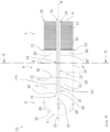
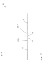
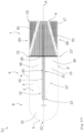
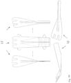
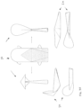
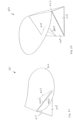
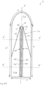
- Figs. 6 and 7 show a blank 1c. In use, the blank 1c folds to form a handheld tool according to another embodiment.
- the blank 1c of Fig. 6 in its structural and functional parts, essentially corresponds to the embodiment of Fig. 1 .
- the blank 1c has a specifically shaped functional section 8 which has an elongated slightly elliptic shape.
- the reason for this specific shape is that the tool which is to be formed out of this blank 1c is a specific type of spoon, similar to a traditional Chinese spoon.
- the handle section 7 is narrow as compared to the widest part of the blank 1c.
- the widest part of the blank 1c is in the intermediate section 9, closer to the functional section 8.
- the angle between the straight segments 12 of the upward bending line 11 is approximately 30.5 degrees.
- the length of the tool is approximately 130 mm, the width at the widest part and at the rear edge 6 are approximately 40 mm and 35 mm respectively.
- the handle section 7, the intermediate section 9, and the functional section have lengths of approximately 40 mm, 60 mm, and 30 mm respectively.
- the middle lane 31 has an additional reinforcement 50 shown as a black stripe in the area of the middle lane 31.
- the reinforcement 50 is formed by embossing. In a general sense, the reinforcement 50 can also be formed by debossing.
- a characteristic feature of the traditional Chinese spoon besides its typical shape and proportions, is the shallowness of the spoon, or more precisely of the cup of the spoon.
- the shallowness of the cup has inter alia an advantage of allowing for rapid cooling of the content of the spoon whilst the spoon is in use.
- the cup of the spoon made out the blank 1c of Fig. 6 does not have a flat bottom. Instead the deepest portion of the cup is defined by the vertex 13.
- the narrowness of the handle section results in a smaller tensile stress along the circumference of the bow 8 and accordingly in a smaller deformation of the bow from the initial plane geometry.
- a shallow form of the cup can be easily achieved.
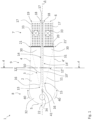
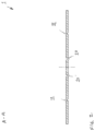
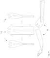
- Figs. 8 and 9 show a blank 1d.
- the blank 1d is used for folding to form a handheld tool according to further embodiment.
- This embodiment corresponds essentially to the embodiment of Fig. 6 and represents a blank 1d for forming a bigger Chinese spoon.
- the functional section 8 and the intermediate section 9 are wider than in the embodiment of Fig. 6 .
- the angle between the straight segments 12 and 12' of the upward bending line 11 is approximately 34.50 degrees.
- the length of the tool is approximately 130 mm, the width at the widest part and at the rear edge 6 is approximately 50 mm and 35 mm, respectively.
- the handle section 7, the intermediate section 9, and the functional section have lengths of approximately 40 mm, 60 mm, and 30 mm, respectively.
- the middle lane 31 has an additional reinforcement 50 in the form of a reinforcement layer provided along the symmetrical axis A of the blank 1d.
- the reinforcement 50 can be provided using blind embossing, which can provide a strong middle lane 31.
- Fig. 10 shows a schematic top view of a blank 1e for folding to form a handheld tool according to another embodiment.
- the blank 1e of Fig. 10 corresponds essentially to the embodiment of Fig. 1 , differing mainly in the front portion of the functional section 8.
- the contour line of the front edge 5 shows two recesses 51 arranged axially symmetrically with respect to the symmetrical axis A of the blank 1e in such a way that three teeth in the functional section 8 are formed.
- the tip 22 of the bow 32 is at the same time the tip of the middle tooth of tine.
- these teeth can serve as fork tines and the tool itself can be used as a fork.
- Fig. 11 shows a schematic top view of a blank 1f for folding to form a handheld tool according to another embodiment.
- the blank 1f of Fig. 11 corresponds essentially to the embodiment of Fig. 3 , differing mainly in the shape of the front portion of the functional section 8 of the blank 1f.
- the contour line of the front edge 5 shows two recesses 51 arranged symmetrically with respect to the symmetrical axis A of the blank 1f in such a way that three teeth in the functional section 8 are formed.
- the tip 22 of the bow 32 is at the same time the tip of the middle tooth of tine. Similar to the embodiment of Fig. 3 , the tip 22 is flat and accordingly the middle tooth of the functional section 8 is flat as well.
- Forming a handheld tool out of the blank 1f shown in Fig. 11 results in a tool with broad teeth, which can be used as both as a fork and as a spoon, and could be used for instance for eating cake, ice cream, spaghetti, or similar.
- Fig. 12 shows a schematic top view of a blank 1g for folding to form a handheld tool according to a further embodiment.
- the blank 1g of Fig. 12 corresponds essentially to the embodiment of Fig. 4 , differing mainly in the shape of the front portion of the functional section 8 of the blank 1g.
- the contour line of the front edge 5 shows two recesses 51 arranged symmetrically with respect to the symmetrical axis A of the blank 1g in such a way that three teeth in the functional section 8 are formed.
- the tip 22 of the bow 32 is at the same time the tip of the middle tooth of tine.
- the three teeth are not blunted. Consequently, forming a handheld tool out of the blank 1g shown in Fig. 12 results in a fork with sharp teeth.
- the fork can be used for handling relatively hard matter, like flower soil, or harder meal, like hard ice cream, or similar.
- Fig. 13 shows a schematic top view of a blank 1h for folding to form a handheld tool according to another embodiment.
- Characteristic for the embodiment of Fig. 13 is a broader middle lane 31 and a flat vertex 13, especially as compared with the embodiment of Fig. 10 . Further, the angle between the straight segments 12 of the upward bending line 11 is approximately 35.25 degrees. This is relatively wide angle, resulting in a shorter intermediate section 9 and a longer handle section 7. Besides, the middle lane 31 is provided with a reinforcement 50 which is indicated by the solid black colour of the middle lane 31.
- Forming a tool out of the blank 1h of Fig. 13 results in a fork of specific geometry which can be used for handling particularly hard matter. Indeed, the reinforcement 50 of the middle lane 31 and the longer handle section 7 allows for the application of particularly large force on the tool without causing damage to the tool.
- Fig. 14 shows a schematic top view of a blank 1i for folding to form a handheld tool according to a further embodiment.
- This embodiment corresponds essentially to the embodiment of Fig. 6 showing a blank 1i for forming a spoon similar to a Chinese spoon.
- the blank 1i of Fig. 14 has two recesses 51 forming three teeth.
- a tool can be formed which essentially resembles a Chinese spoon, but which can be used as a fork.
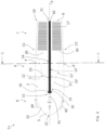
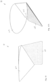
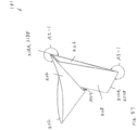
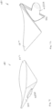
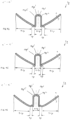
- Figs. 15 and 16 show a blank 1j, which is intended for folding to form a handheld tool according to another embodiment.
- the blank 1j shown in Fig. 15 comprises two corner wings 60 or corner wings at two handle section corners adjacent to the rear edge 6 of the blank 1j.
- the handle wings 60 are demarcated from respective side wings 30 by two handle bending lines 61.
- the handle bending lines 61 extend from the rear edge 6 of the blank 1j to the respective endpoint 21, 21' at the respective side edge 4, 4' of the blank 1j.
- the handle bending lines 61 facilitate bending of the handle wings 60, in particular, bending down from the figure plane away from the viewer, as indicated by the downward movement symbols 33.
- the basic material of the blank 1j of Fig. 15 is silicone. With silicone as its basic material, the blank 1j can be formed into a durable silicone-based tool, such as a reliable silicone-based kitchen utensil.
- the blank 1j also comprises a middle lane 31 with a reinforcement in the form of an embedded metal sheet 31a which is shown as a dark portion of blank 1j along the symmetrical axis A. This extends along the symmetrical axis A from the vertex 13 towards the rear edge 6 and terminates in the handle section 7 before reaching the rear edge 6.
- the metal sheet 31a enables the middle lane 31 to be stiff and stable. In other words, the middle lane 31 can bear more weight or stress.
- the embodiment of Fig. 15 comprises a reinforcement in the handle section 7, in particular in the handle wings 60. This is shown as dark triangles in the handle wings 60.
- the reinforcement of the handle wings comprises extrusion moulded silicone.
- the reinforcement may comprise one or more metal layers embedded in the blank 1j in the region of the middle lane 31 and in the handle wings 60.
- the reinforcement may comprise surface layers laminated on the blank 1j, particularly at locations which are exposed to increased strain, like the middle lane 31, especially in the vicinity of the vertex 13 or the handle section, which is grasped by the user while using the tool.
- the front edge 5 is straight such that the tip 22 of the front portion is essentially flat.
- the length of the tool is approximately 160 mm, and the width approximately 40 mm.
- the handle section 7, the intermediate section 9, and the functional section have lengths of approximately 50 mm, 80 mm, and 40, respectively.
- the angle between the straight segments 12 of the upward bending line 11 is approximately 25.90 degrees.
- the dimensions, especially the length of the intermediate section 9 and the functional section 8, as well as the angle between the straight segments 12 of the upward bending lines 11 may vary significantly depending on the purpose of the tool.
- the length of the tool is approximately 160 mm, and the width approximately 40 mm.
- the handle section 7, the intermediate section 9, and the functional section have respective lengths of approximately 50 mm, 80 mm, and 30 mm.
- the width of the middle lane 31 is approximately 4 mm.
- the blank 1j also comprises grip structures or grippers.
- the grippers in this embodiment are provided in the form of elongated structures or stripes of protruded silicone.
- the grippers with coloured patterns are provided in the handle section 7.
- the colour pattern and the geometry of the grippers may vary, depending on the specific design of tool.
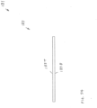
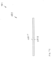
- Fig. 17 shows a cross-sectional view of a variant of the blank of Fig. 15 .
- Fig. 17 show a blank 1ja that comprises silicone material.
- the blank 1jb includes a middle lane 31, which comprises an enlarged body for reinforcing the middle lane 31.
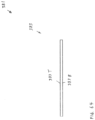
- Fig. 18 shows a cross-sectional view of another variant of the blank of Fig. 15 .
- Fig. 18 shows a blank 1jb.
- the blank 1jb includes a middle lane 31, which comprises a metal sheet 31b that is attached to an outer surface of a body of the middle lane 31 for reinforcing the middle lane 31.
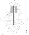
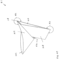
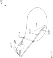
- Fig. 19 shows a schematic top view of a blank 1k for folding to form a handheld tool according to a further embodiment.
- the blank 1k shown in Fig. 19 corresponds in its essential features to the embodiment of Fig. 15 , and shows some differences as well, especially in the design of the handle section 7 and of the functional section.
- the bumps 17 in the handle section 7 are round or dot-shaped.
- the front edge 5 has a circular shape such the tip 22 of the front portion or the function section 8 is essentially round.
- the length of the tool is approximately 110 mm, and the width approximately 40 mm.
- the handle section 7, the intermediate section 9, and the functional section have lengths of approximately 50 mm, 30 mm, and 30 mm, respectively.
- the width of the middle lane 31 is approximately 2 mm.
- the angle between the straight segments 12 of the upward bending line 11 is approximately 66.00 degrees.
- the blank 1k in the folded state results in a tool which is specifically suitable for using as a small scoop for ice-cream or rice, or as a ladle by bending the segment 8 in the other direction.
- the blank 1k comprises magnetized metal plates for ease of use.
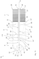
- Fig. 20 shows a schematic top view of a blank 11 for folding to form a handheld tool according to another embodiment.
- Fig. 20 differs from the embodiment of Fig. 19 by the lengthwise orientation of the bumps in the handle section 7 as well as in the dimensions.
- the length of the tool is approximately 140 mm, and the width approximately 40 mm.
- the handle section 7, the intermediate section 9, and the functional section have lengths of approximately 50 mm, 60 mm, and 30 mm, respectively.
- the width of the middle lane 31 is approximately 4 mm.
- the angle between the straight segments 12 of the upward bending line 11 is approximately 34.10 degrees.
- Such dimensions and shape of the blank 11 make the blank 11 suitable for forming a tool which can be used as a ladle, scoop, spatula, funnel, spade or shovel.
- Fig. 21 shows a schematic top view of a blank 1m for folding to form a handheld tool according to another embodiment.
- This embodiment corresponds to the embodiment of Fig. 20 and differs mainly in the shape of the functional section 8.
- the tip 22 of the functional section 8 is flat such that the blank 1m has essentially the shape of a rectangle with rounded corners.
- a tool formed out of such a blank 1m is particularly suitable for usage as a spatula, scraper, funnel, spade or shovel.
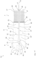
- Fig. 22 shows a schematic top view of a blank 1n for folding to form a handheld tool according to a further embodiment.
- the blank 1n of Fig. 22 corresponds essentially to the embodiment of Fig. 19 and differs mainly in the shape of the functional section 8 and in the proportions.
- the functional section 8 is longer and the tip 22 of the functional section 8 has a rounded elliptic shape.
- a plurality of holes 70 are provided. One of the holes is provided at the tip of the vertex 13.
- the middle lane 31 with a reinforcement extends along the symmetrical axis A of the blank 1n over the intermediate section 9 and the handle section 7 without reaching the vertex 13 and the rear edge 6.
- the length of the tool is approximately 140 mm, and the width approximately 40 mm.
- the handle section 7, the intermediate section 9, and the functional section have lengths of approximately 50 mm, 50 mm, and 40 mm, respectively.
- the width of the middle lane 31 is approximately 2 mm.
- the angle between the straight segments 12 of the upward bending line 11 is approximately 41 degrees.
- the hole 70 at the vertex can serve for stress release and can facilitate the forming of the tool.
- the particular shape and the holes 70 make the blank 1n particularly suitable for forming tools which can be used as a strainer, scoop or similar.
- the plurality of holes 70 can be die-cut in the blank 1n.
- the holes are essentially round and have a diameter of approximately 1.5 mm.
- the diameter of the holes can be varied, in particular in the range from 1 mm up to 3 mm, depending on the purpose of the tool.
- no holes in the functional section 8 and at the vertex 13 are provided.
- the middle lane and the reinforcement of the middle lane 31 can be extended to the vertex 13.
- Tools shaped out of such embodiments can be used for example as a spatula, scoop or ladle.
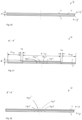
- Fig. 23 shows schematically a possible panel arrangement for producing a blank according an embodiment.
- a row of blanks according to the embodiment of Fig. 3 is shown.
- the blanks in the upper row are arranged in alternating orientation.
- every second blank is oriented with its functional part up and with its handle part down.
- the tapered shape of blanks along with the design's technical importance discussed above, has an advantage from the manufacturing point of view.
- worksheet material and production costs can be saved by alternating the orientation of adjacent blanks in the worksheet.
- a saving of more than 10 % in worksheet material in the bulk production can easily be achieved.
- two blanks are produced and die-cut out of a single workpiece or worksheet. Due to the tapered shape of the blank, up to approximately 6 % of material savings can be achieved, depending on the specific design of the blank.
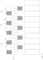
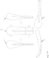
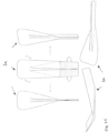
- Figs. 24 to 37 show different embodiments of the blank in its initial and in its folded state from different views.
- FIG. 24 to 33 a top view of a blank according to a respective embodiment in an unfolded or initial state is shown.
- Figs. 24 to 33 correspond to the embodiments shown in Figs. 1 to 14 above.
- Figs. 34 to 37 correspond essentially to the embodiments shown in Figs. 15 to 22 but also include some important modifications.
- the embodiments of Figs, 27 to 30 comprise a reinforcement.
- the reinforcement can be provided using blind emboss.
- the reinforcement can be provided using extrusion-moulded silicone. This area with the reinforcement is shown in the figures as a dark in particular triangular area extending from the vertex to the handle section.
- an extrusion-moulded rubber is used, as a reinforcement.
- a middle lane in the form of a stripe extending along the symmetrical axis A is missing. Instead, a middle lane or middle channel is created together with the folding of the side wings. Similar to the middle lane, the middle channel or tube has the same supporting effect and contributes to the robustness of the tool.
- the tools formed out of the blanks according the embodiments can be in general easily modified or transformed by changing the bending direction of the functional part of the blank.
- an energetically favourable stable configuration can also be achieved when the front portion of the functional section is bent in the same direction with respect to the plane of the middle lane as the side wings.
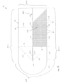
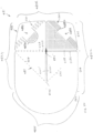
- Figs. 38 to 47 illustrate a variant of the blank of Fig. 1 .
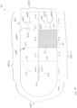
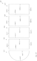
- Fig. 38 shows a thin blank 81 for folding to form a desired cup with a handle.
- the cup can also refer to a bowl, a container, or a scoop.
- the thin blank 81 includes an elongated sheet 83 with a plurality of scored lines 85 and with a plurality of bumps 87.
- the scored lines 85 and the bumps 87 are located on surfaces of the sheet 83.
- Each scored line 85 includes a narrow hollow channel, to a bending groove, or to a narrow elongated depressed area for facilitating bending or folding of the blank 81 to form a desired cup.
- the depth and the width of the scored line are adapted according to material, to thickness, and to purpose of the blank 81.
- the elongated sheet 83 is essentially flat and is symmetrical about its longitudinal axis.
- the sheet 83 has a top surface 83T with a bottom surface 83B being provided opposite to the top surface 83T, as shown in Fig. 44 .
- the sheet 83 also has a first side edge 83S1 with a second side edge 83S2 being provided opposite to the first side edge 83S1, and a front edge 83F with a rear edge 83R being provided opposite to the front edge 83F, as illustrated in Fig. 38 .
- the scored line 85 can be placed on the top surface 83T of the blank 83. Such top surface scored line is also called a downward bending line. Similarly, the scored line 85 can be placed on the bottom surface 83B of the blank 83. Such bottom surface scored line is also called an upward bending line.
- the front edge 83F and the rear edge 83R are placed at longitudinal ends of the sheet 83.
- the front edge 83F is connected to the first side edge 83S1, which is connected to the rear edge 83R.
- the rear edge 83R is connected to the second side edge 83S2, which is connected to the front edge 83F.
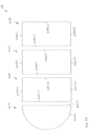
- the sheet 83 also comprises a semi-circular portion 102, a first rectangular portion 104, a second rectangular portion 106, and a third rectangular portion 108, as illustrated in Fig. 43 .
- the semi-circular portion 102 is placed next to the first rectangular portion 104, which is placed next to the second rectangular portion 106.
- the second rectangular portion 106 is placed next to the third rectangular portion 108.
- the semi-circular portion 102 and the first rectangular portion 104 forms a partial stadium portion.
- the partial stadium portion with a generally rectangular shape that has three straight lines and one circular line.
- the semi-circular portion 102 comprises an arc edge 102A and a straight edge 102S. Ends of the arc edge 102A are placed next to respective ends of the straight edge 102S.
- the first rectangular portion 104 includes a first-long edge 104L1 with a second-long edge 104L2, which is placed opposite to the first-long edge 104L1, and a first-short edge 104S1 with a second-short edge 104S2, which is placed opposite to the first-short edge 104S1.
- a first end of the first-long edge 104L1 is placed next to a first end of the first-short edge 104S1.
- a second end of the first-short edge 104S1 is placed next to a first end of the second-long edge 104L2.
- a second end of the second-long edge 104L2 is placed next to a first end of the second-short edge 104S2.
- a second end of the second-short edge 104S2 is placed next to a second end of the first-long edge 104L1.
- the second rectangular portion 106 includes a first-long edge 106L1 with a second-long edge 106L2, and a first-short edge 106S1 with a second-short edge 106S2.
- the third rectangular portion 108 includes a first-long edge 108L1 with a second-long edge 108L2, and a first-short edge 108S1 with a second-short edge 108S2.
- the arc edge 102A is placed next to the front edge 83F.
- the straight edge 102S is placed next to the first-long edge 104L1 of the first rectangular portion 104.
- the first-short edge 104S1 is placed next to the first side edge 83S1.
- the second short edge 104S2 is placed next to the second side edge 83S2.
- the second-long edge 104L2 is placed next to the first-long edge 106L1 of the second rectangular portion 106.
- the first-short edge 106S1 is placed next to the first side edge 83S1.
- the second short edge 106S2 is placed next to the second side edge 83S2.
- the second-long edge 106L2 is placed next to the first-long edge 108L1 of the third rectangular portion 108.
- the first-short edge 108S1 is placed next to the first side edge 83S1.
- the second short edge 108S2 is placed next to the second side edge 83S2.
- the second-long edge 108L2 is placed next to the rear edge 83R.
- the straight edge 102S of the semi-circular portion 102, the long edges 104L1 and 104L2 of the first rectangular portion 104, the long edges 106L1 and 106L2 of the second rectangular portion 106, and the long edges 108L1 and 108L2 of the third rectangular portion 108 have the same length.
- the first short edge 104S1 of the first rectangular portion 104, the first short edge 106S1 of the second rectangular portion 106, and the first short edge 108S1 of the third rectangular portion 108 are placed such that they form a straight line.
- the second short edge 104S2 of the first rectangular portion 104, the second short edge 106S2 of the second rectangular portion 106, and the second short edge 108S2 of the third rectangular portion 108 are placed such that they form a straight line.
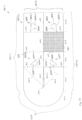
- scored lines 85 they include a set of longitudinal-scored lines, a set of lateral-scored lines, and a set of diagonal-scored lines.
- the longitudinal-scored lines include a first longitudinal bending line, which is also called a short valley spine.
- the longitudinal-scored lines also include a second longitudinal bending line, and a third longitudinal bending line.
- the first longitudinal bending line includes a circular bending line segment 110C and a first straight bending line segment 110S1 with a second straight bending line segment 110S2.
- the circular bending line segment 110C is placed on the bottom surface 83B while the first straight bending line segment 110S1 and the second straight bending line segment 110S2 are placed on the top surface 83T.
- a first end of the circular bending line segment 110C is placed next to a first end of the first straight bending line segment 110S1.
- a second end of the first straight bending line segment 110S1 is placed next to a first end of the second straight bending line segment 110S2.
- a second end of the second straight bending line segment 110S2 is placed next to a second end of the circular bending line segment 110C.
- the first straight bending line segment 110S1 and the second straight bending line segment 110S2 form a small angle.
- the circular bending line segment 110C is placed at a midpoint of the straight edge 102S of the semi-circular portion 102.
- the second end of the first straight bending line segment 110S1 and the first end of the second straight bending line segment 110S2 are placed at a midpoint of the first long edge 106L1 of the second rectangular portion 106.
- the second longitudinal bending line includes a straight bending line segment 112, which is placed on the top surface 83T.
- the straight bending line segment 112 extends from a midpoint of the first long edge 106L1 to a midpoint of the second long edge 106L2 of the second rectangular portion 106.
- the third longitudinal bending line includes a straight bending line segment 114, which is placed on the top surface 83T.
- the straight bending line segment 114 extends from a midpoint of the first long edge 108L1 to a midpoint of the second long edge 108L2 of the third rectangular portion 108.
- the lateral-scored lines include a first straight bending line segment 116, a second straight bending line segment 118, a third straight bending line segment 120, and a fourth straight bending line segment 122.
- the first straight bending line segment 116 is placed on the bottom surface 83B and it extends from one end of the first long edge 106L1 of the second rectangular portion 106, which is placed next to the first side edge 83S1, to a midpoint of the first long edge 106L1 of the second rectangular portion 106.
- the second straight bending line segment 118 is placed on the top surface 83T and it extends from the midpoint of the first long edge 106L1 of the second rectangular portion 106 to one end of the first long edge 106L1 of the second rectangular portion 106, which is placed next to the second side edge 83S2.
- the third straight bending line segment 120 is placed on the bottom surface 83B and it extends from one end of the first long edge 108L1 of the third rectangular portion 108, which is placed next to the first side edge 83S1, to a midpoint of the first long edge 108L1 of the third rectangular portion 108.
- the fourth straight bending line segment 122 is placed on the top surface 83T and it extends from the midpoint of the first long edge 108L1 of the third rectangular portion 108 to one end of the first long edge 108L1 of the third rectangular portion 108, which is placed next to the second side edge 83S2.
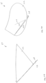
- the set of diagonal-scored lines include a first straight bending line segment 124 and a second straight bending line segment 126.
- the first straight bending line segment 124 is placed on the bottom surface 83B and it extends from a midpoint of the straight edge 102S of the semi-circular portion 102 to one end of the second-long edge 104L2 of the first rectangular portion 104, which is placed at the first side edge 83S1.
- the second straight bending line segment 126 is placed on the bottom surface 83B and it extends from the midpoint of the straight edge 102S of the semi-circular portion 102 and it extends towards one end of the second-long edge 104L2 of the first rectangular portion 104, which is placed at the second side edge 83S2.
- One end of the second straight bending line segment 126 is placed on the midpoint of the straight edge 102S of the semi-circular portion 102. Another end of the second straight bending line segment 126 is placed on a point, which lies on about midpoint between the midpoint of the straight edge 102S and the one end of the second-long edge 104L2 of the first rectangular portion 104, which is placed at the second side edge 83S2.
- bumps 87 they are placed on a first elevated part and on a second elevated part of the blank 81.
- the first elevated part is enclosed by a part of the first long edge 106L1, a part of the second-long edge 106L2, and the second short edge 106S2 of the second rectangular portion 106, as well as the straight bending line segment 112.
- the second elevated part is enclosed by a part of the first long edge 108L1, a part of the second-long edge 108L2, and the second short edge 108S2 of the third rectangular portion 108, as well as the straight bending line segment of the straight bending line segment 114.
- a curve line or rounded corner 130 is provided at one end of the third straight bending line segment 120, which is placed next to the first side edge 83S1.
- a curve line or rounded corner 132 is provided at one end of the third straight bending line segment 120, which is placed next to one end of the fourth straight bending line segment 122.
- a curve line or rounded corner 134 is also provided at another end of the fourth straight bending line segment 122, which is placed next to the second side edge 83S2.
- the blank 81 which comprises a thin material, has a length of approximately 285 mm and a width of approximately 120 mm.
- the semi-circular portion 102 has a radius of about 60 mm.
- the first-short edge 104S1 and the second-short edge 104S2 have a length of about 60 mm and the first-long edge 104L1 and the second-long edge 104L2 have a length of about 120 mm.
- the first-short edge 106S1 has a length of about 82.5 mm
- the second-short edge 106S2 has a length of about 83.0 mm
- the first-long edge 106L1 and the second-long edge 106L2 have a length of about 120 mm.
- the first-short edge 108S1 has a length of about 80.0 mm
- the second-short edge 108S2 has a length of about 82.0 mm
- the first-long edge 108L1 has a length of about 120 mm
- the second-long edge 108L2 has a length of about 118 mm.
- the first straight bending line segment 124 of the diagonal-scored lines forms an angle of about 45 degrees with the first side edge 83S1.
- the blank 81 which comprises a thin material, has a length of approximately 243.5 mm and a width of approximately 120 mm.
- the semi-circular portion 102 has a radius of about 60 mm.
- the first-short edge 104S1 and the second-short edge 104S2 have a length of about 60 mm and the first-long edge 104L1 and the second-long edge 104L2 have a length of about 120 mm.
- the first-short edge 106S1 has a length of about 59.0 mm
- the second-short edge 106S2 has a length of about 60.0 mm
- the first-long edge 106L1 and the second-long edge 106L2 have a length of about 120 mm.
- the first-short edge 108S1 has a length of about 57.0 mm
- the second-short edge 108S2 has a length of about 59.0 mm
- the first-long edge 108L1 has a length of about 120 mm
- the second-long edge 108L2 has a length of about 118 mm.
- the first straight bending line segment 124 of the diagonal-scored lines forms an angle of about 45 degrees with the first side edge 83S1.
- the blank 81 is produced using food grade synthetic papers, which are extruded from polypropylene pellets.
- the synthetic paper has a weight value of about 250 grams per square meter (GSM) to about 350 GSM.
- the blank 81 can also be produced using other food grade materials, such as folding boxboard (FBB), solid bleached sulphate (SBS), and ivory board.
- FBB folding boxboard
- SBS solid bleached sulphate
- the FBB, the SBS, and the ivory board can have a weight value of about 200 grams per square meter (GSM) to about 400 GSM.
- the blank 81 can be folded manually to form a cup, which is illustrated in Figs. 39 to 42 .
- the scored lines 85 are intended for bending parts of the blank to bend in different pre-determined directions.
- the semi-circular portion 102 and the first rectangular portion 104 are intended for folding to form a container portion of the cup.
- the second rectangular portion 106 and the third rectangular portion 108 are intended for folding to form a handle portion of the cup.
- the first straight bending line segment 124, the circular bending line segment 110C, and the second straight bending line segment 126 are adapted such that they form a smooth linen which does not cut a user of the cup.
- the rounded corners act to provide safety to prevent cutting of a user of the cup.
- the rounded corners also act to increase durability and act to provide a sturdier formation. This is different from pointed corners that break or damage more easily.
- the cup can serve as a spoon with an active or functional top side, a scoop with an active bottom side, a scraper with an active bottom side, or a funnel with an active bottom side.
- Figs. 45 , 46 , and 47 show a method of folding the blank 81 to form a cup with a handle.
- the method includes a step of folding the flat blank 81 along the straight bending line segments 112 and the 114, as indicated by an arrow A1, which is shown in Figs. 45 and 46 .
- This causes the semi-circular portion 102 and the first rectangular portion 104 to fold for forming a container portion while the second rectangular portion 106 and the third rectangular portion 108 folds to form an initial handle portion of the cup.
- the blank 81 is folded along the straight bending line segment 118, as indicated by an arrow A2, which is shown in Figs. 45 , 46 , and 47 .
- the container portion is then inclined at an acute angle with respect to the handle portion.
- the blank 81 is then folded along the straight bending line segment 122, as indicated by an arrow A3, which is shown in Figs. 45 , 46 , and 47 .
- the handle portion is bent about straight bending line segment 122.
- the third rectangular portion 108 is later inserted into a slit that is formed by the folded first rectangular portion 104, as indicated by an arrow A4, which is shown in Fig. 47 , wherein the second rectangular portion 106 and the third rectangular portion 108 are bent and placed to form the final handle portion of the cup.
- Figs. 48 to 57 illustrate another variant of the blank of Fig. 1 .
- Fig. 48 shows a thick blank for folding to form a cup with a handle.
- the thick blank of Fig. 48 is a variant of the thin blank of Fig. 38 .
- the thick blank of Fig. 48 and the blank of Fig. 38 have similar parts.
- Fig. 48 shows a thick blank 181 for folding to form a desired cup with a handle.
- the thick blank 181 comprises an elongated sheet 183 with a plurality of scored lines 185 and with a plurality of bumps 187.
- the scored lines 185 and the bumps 187 are located on surfaces of the sheet 183.
- the elongated sheet 183 is essentially flat and is symmetrical about its longitudinal axis.
- the sheet 183 has a top surface 183T with a bottom surface 183B being provided opposite to the top surface 183T.
- the sheet 183 also has a first side edge 183S1 with a second side edge 183S2 being provided opposite to the first side edge 183S1, and a front edge 183F with a rear edge 183R being provided opposite to the front edge 183F, as illustrated in Fig. 48 .
- the sheet 183 also comprises a semi-circular portion 202, a first rectangular portion 204, a second rectangular portion 206, and a third rectangular portion 208.
- the semi-circular portion 202 is placed next to the first rectangular portion 204, which is placed next to the second rectangular portion 206.
- the second rectangular portion 206 is placed next to the third rectangular portion 208.
- the semi-circular portion 202 comprises an arc edge 202A and a straight edge 202S. Ends of the arc edge 202A are placed next to respective ends of the straight edge 202S.
- the first rectangular portion 204 includes a first-long edge 204L1 with a second-long edge 204L2, which is placed opposite to the first-long edge 204L1, and a first-short edge 204S1 with a second-short edge 204S2, which is placed opposite to the first-short edge 204S1.
- the second rectangular portion 206 includes a first-long edge 206L1 with a second-long edge 206L2, and a first-short edge 206S1 with a second-short edge 206S2.
- the third rectangular portion 208 includes a first-long edge 208L1 with a second-long edge 208L2, and a first-short edge 208S1 with a second-short edge 208S2.
- scored lines 185 they include a longitudinal-scored line, a set of lateral-scored lines, and a set of diagonal-scored lines.
- the longitudinal-scored line includes a longitudinal bending line.
- the longitudinal-scored line is also called a long valley spine.
- the longitudinal bending line include a circular bending line segment 210C and a first straight bending line segment 210S1 with a second straight bending line segment 210S2.
- the circular bending line segment 210C is placed on the bottom surface 183B while the first straight bending line segment 210S1 and the second straight bending line segment 210S2 are placed on the top surface 183T.
- a first end of the circular bending line segment 210C is placed next to a first end of the first straight bending line segment 210S1.
- a second end of the first straight bending line segment 210S1 is placed next to a first end of the second straight bending line segment 210S2.
- a second end of the second straight bending line segment 210S2 is placed next to a second end of the circular bending line segment 210C.
- the first end of the first straight bending line segment 210S1 and the second end of the second straight bending line segment 210S2 are separated by a distance of about 2 mm.
- the second end of the first straight bending line segment 210S1 is in contact with the first end of the second straight bending line segment 210S2.
- the first straight bending line segment 210S1 and the second straight bending line segment 210S2 form a small angle.
- the circular bending line segment 210C is placed at a midpoint of the straight edge 202S of the semi-circular portion 202.
- the second end of the first straight bending line segment 210S1 and the first end of the second straight bending line segment 210S2 are placed at a midpoint of the second-long edge 206L2 of the second rectangular portion 206.
- the first straight bending line segment 210S1 and the first end of the second straight bending line segment 210S2 extends from around the midpoint of the straight edge 202S of the semi-circular portion 202, across the first rectangular portion 204, across the second rectangular portion 206, and across the third rectangular portion 208.
- the lateral-scored lines include a pair of first straight bending line segments 216A and 216B, a pair of second straight bending line segments 218A and 218B, a pair of third straight bending line segments 220A and 220B, and a pair of fourth straight bending line segments 222A and 222B.
- first straight bending line segments 216A and 216B are placed on the bottom surface 183B. They extend from the vicinity of one end of the first long edge 206L1 of the second rectangular portion 206, which is placed next to the first side edge 83S1, to the vicinity of a midpoint of the first long edge 106L1 of the second rectangular portion 206.
- the first straight bending line segments 216A and 216B are placed essentially parallel and close to each other.
- the second straight bending line segments 218A and 218B are placed on the top surface 183T. They extend from the vicinity of the midpoint of the first long edge 206L1 of the second rectangular portion 206 to the vicinity of one end of the first long edge 206L1 of the second rectangular portion 206, which is placed next to the second side edge 183S2.
- the second straight bending line segments 218A and 218B are placed essentially parallel and close to each other.
- the third straight bending line segments 220A and 220B are placed on the bottom surface 183B. They extend from the vicinity of one end of the first long edge 208L1 of the third rectangular portion 208, which is placed next to the first side edge 183S1, to the vicinity of a midpoint of the first long edge 208L1 of the third rectangular portion 208.
- the first straight bending line segments 220A and 220B are placed essentially parallel and close to each other.
- the fourth straight bending line segment 222A and 222B are placed on the top surface 183T. They extend from the vicinity of the midpoint of the first long edge 208L1 of the third rectangular portion 208 to the vicinity of one end of the first long edge 208L1 of the third rectangular portion 208, which is placed next to the second side edge 183S2.
- the first straight bending line segments 222A and 222B are placed essentially parallel and close to each other.
- the set of diagonal-scored lines include a first straight bending line segment 224 and a second straight bending line segment 226.
- the first straight bending line segment 224 is placed on the bottom surface 183B and it extends from a midpoint of the straight edge 202S of the semi-circular portion 202 to one end of the second long edge 204L2 of the first rectangular portion 204, which is placed at the first side edge 183S1.
- the second straight bending line segment 226 is placed on the bottom surface 183B and it extends from the midpoint of the straight edge 202S of the semi-circular portion 202 and it extends in the direction of one end of the second long edge 204L2 of the first rectangular portion 204, which is placed at the second side edge 183S2.
- One end of the second straight bending line segment 226 is placed on the midpoint of the straight edge 202S of the semi-circular portion 202. Another end of the second straight bending line segment 226 is placed on a point, which lies on about midpoint between the midpoint of the straight edge 202S and the one end of the second long edge 204L2 of the first rectangular portion 204, which is placed at the second side edge 183S2.
- bumps 187 they are placed on a first elevated part and on a second elevated part of the blank 181.
- the first elevated part is enclosed by a part of the first long edge 206L1, a part of the second long edge 206L2, and the second short edge 206S2 of the second rectangular portion 206, as well as the straight bending line segment 210S2 of the longitudinal bending line.
- the second elevated part is enclosed by a part of the first long edge 208L1, a part of the second long edge 208L2, and the second short edge 208S2 of the third rectangular portion 208, as well as the straight bending line segment 210S2 of the longitudinal bending line.
- a first trapezoid indentation or opening 228 is provided at ends of the first straight bending line segments 216A and 216B, which is placed in the vicinity of ends of the second straight bending line segments 218A and 218B.
- a second trapezoid indentation 230 is provided at ends of the third straight bending line segments 220A and 220B, which is placed in the vicinity of ends of the fourth straight bending line segments 222A and 222B.
- the blank 181 has a length of approximately 285 mm and a width of approximately 120 mm.
- the semi-circular portion 202 has a radius of about 60 mm.
- the first-short edge 204S1 and the second-short edge 204S2 have a length of about 60 mm and the first-long edge 204L1 and the second-long edge 204L2 have a length of about 120 mm.
- the first-short edge 206S1 has a length of about 80.5 mm
- the second-short edge 206S2 has a length of about 81.5 mm
- the first-long edge 206L1 and the second-long edge 206L2 have a length of about 120 mm.
- the middle part of the second rectangular portion 206 has a width of about 81.0 mm.
- the first-short edge 208S1 has a length of about 77.3 mm
- the second-short edge 208S2 has a length of about 77.8 mm
- the first-long edge 208L1 has a length of about 120 mm.
- the middle part of the third rectangular portion 208 has a width of about 80.0 mm.
- the first straight bending line segment 224 of the diagonal-scored lines forms an angle of about 45 degrees with the first side edge 183S1.
- the circular bending line segment 210C has a minimal diameter of about 3 mm.
- the first straight bending line segment 210S1 and the second straight bending line segment 210S2 has a separation of about 2 mm minimal at one end and about 0 mm at another end.
- the blank 181 has a length from approximately 243.5 mm and a width of approximately 120 mm.
- the semi-circular portion 202 has a radius of about 60 mm.
- the first-short edge 204S1 and the second-short edge 204S2 have a length of about 60 mm and the first-long edge 204L1 and the second-long edge 204L2 have a length of about 120 mm.
- the first-short edge 206S1 has a length of about 60.0 mm
- the second-short edge 206S2 has a length of about 60.5 mm
- the first-long edge 206L1 and the second-long edge 206L2 have a length of about 120 mm.
- the first-short edge 208S1 has a length of about 56.5 mm
- the second-short edge 208S2 has a length of about 57.0 mm
- the first-long edge 208L1 has a length of about 120 mm.
- the middle part of the third rectangular portion 208 has a width of about 59.0 mm.
- the first straight bending line segment 224 of the diagonal-scored lines forms an angle of about 45 degrees with the first side edge 183S1.
- the circular bending line segment 210C has a minimal diameter of about 3 mm.
- the first straight bending line segment 210S1 and the second straight bending line segment 210S2 has a separation of about 2 mm minimal at one end and about 0 mm at another end.
- the blank 181 can be folded manually to form a cup, which is illustrated in Figs. 49 to 52 .
- the semi-circular portion 202 and the first rectangular portion 204 are intended for folding to form a container portion of the cup.
- the second rectangular portion 206 and the third rectangular portion 208 are intended for folding to form a handle portion of the cup.
- the scored lines 185 are intended for bending parts of the blank to bend in different pre-determined directions.
- the parallel and close straight bending line segments 216A and 216B allow for easier folding of respective thick parts of blank 181.
- the parallel and close straight bending line segment 220A and 220B, and the parallel and close straight bending line segment 222A and 222B allow for easier folding of respective thick parts of blank 181.
- the almost parallel and close bending line segments 210S1 and 210S2 allow for easier folding of respective thick parts of blank 181.
- trapezoid indentations 228 and 230 allow for easier folding of respective thick parts of blank 181.
- the trapezoid indentations 228 and 230 act to contain material thickness of the blank 181. When the blank 181 is bent, the bent area often enlarges, especially in corners. This enlarging can deter the bending of the blank 181.
- the trapezoid indentations 228 and 230 serve to receive the enlarged area to allow for easier bending of the blank 181.
- these trapezoid indentations 228 and 230 also allow for secure and stable formation of the cup and stable formation of its stand.
- Figs. 55 , 56 , and 57 show a method of folding the blank 81 to form a cup with a handle.
- the method includes a step of folding the flat blank 181 along the straight bending line segments 210S1 and 210S2, as indicated by an arrow A1-1, which is shown in Figs. 55 and 56 .
- the semi-circular portion 202 and the first rectangular portion 204 then fold to form a container portion while the second rectangular portion 206 and the third rectangular portion 208 are folded to form an initial handle portion of the cup.
- the blank 181 is folded along the straight bending line segments 218A and 218B, as indicated by an arrow A2-1, which is shown in Figs. 55 , 56 , and 57 .
- the container portion is then inclined at an acute angle with respect to the handle portion.
- the blank 181 is then folded along the straight bending line segments 222A and 222B, as indicated by an arrow A3-1, which is shown in Figs. 55 , 56 , and 57 . Put differently, the handle portion is bent about the straight bending line segments 222A and 222B.
- the third rectangular portion 208 is later inserted into a slit that is formed by the folded first rectangular portion 204, as indicated by an arrow A4-1, which is shown in Fig. 57 .
- the second rectangular portion 206 and the third rectangular portion 208 are bent and placed to form the final handle portion of the cup.
- Figs. 58 to 67 illustrate a variant of the blank of Fig. 1 .
- Fig. 58 shows a thin blank 381 for folding to form a desired cup with a stand.
- the blank 381 and the blank 81 of Fig. 38 have similar parts.
- the similar parts may have the same or similar part numbers.
- the cup can also refer to a bowl, a container, or a scoop.
- the thin blank 381 includes an elongated sheet 383 with a plurality of scored lines 385, with a plurality of bumps 387 and with two flap parts 388A and 388B.
- the scored lines 385 and the bumps 387 are located on surfaces of the sheet 383.
- the elongated sheet 383 is essentially flat and is symmetrical about its longitudinal axis.
- the sheet 383 has a top surface 383T with a bottom surface 383B being provided opposite to the top surface 383T, as shown in Fig. 64 .
- the sheet 383 also has a first side edge 383S1 with a second side edge 383S2 being provided opposite to the first side edge 383S1, and a front edge 383F with a rear edge 383R being provided opposite to the front edge 383F, as illustrated in Fig. 58 .
- the front edge 383F and the rear edge 383R are placed at longitudinal ends of the sheet 383.
- the front edge 383F is connected to the first side edge 383S1, which is connected to the rear edge 383R.
- the rear edge 383R is connected to the second side edge 383S2, which is connected to the front edge 383F.
- the sheet 383 also comprises a semi-circular portion 402, a first rectangular portion 404, a second rectangular portion 406, a third rectangular portion 408, and a fourth rectangular portion 409, as illustrated in Fig. 63 .
- the semi-circular portion 402 is placed next to the first rectangular portion 404, which is placed next to the second rectangular portion 406.
- the second rectangular portion 406 is placed next to the third rectangular portion 408, which is placed next to the fourth rectangular portion 409.
- the semi-circular portion 402 comprises an arc edge 402A and a straight edge 402S. Ends of the arc edge 402A are placed next to respective ends of the straight edge 402S.
- the first rectangular portion 404 includes a first-long edge 404L1 with a second-long edge 4104L2, which is placed opposite to the first-long edge 404L1, and a first-short edge 404S1 with a second-short edge 404S2, which is placed opposite to the first-short edge 404S1.
- the second rectangular portion 406 includes a first-long edge 406L1 with a second-long edge 406L2, and a first-short edge 406S1 with a second-short edge 406S2.
- the third rectangular portion 408 includes a first-long edge 408L1 with a second-long edge 408L2, and a first-short edge 408S1 with a second-short edge 408S2.
- the fourth rectangular portion 409 includes a first-long edge 409L1 with a second-long edge 409L2, and a first-short edge 409S1 with a second-short edge 409S2.
- scored lines 385 they include a set of longitudinal-scored lines, a set of lateral-scored lines, and a set of diagonal-scored lines.
- the longitudinal-scored lines include a first longitudinal bending line and a second longitudinal bending line, a third longitudinal bending line, and a fourth longitudinal bending line.
- the first longitudinal bending line includes a circular bending line segment 410C and a first straight bending line segment 410S1 with a second straight bending line segment 410S2.
- the circular bending line segment 410C is placed on the bottom surface 383B while the first straight bending line segment 410S1 and the second straight bending line segment 410S2 are placed on the top surface 383T.
- a first end of the circular bending line segment 410C is placed next to a first end of the first straight bending line segment 410S1.
- a second end of the first straight bending line segment 410S1 is placed next to a first end of the second straight bending line segment 410S2.
- a second end of the second straight bending line segment 410S2 is placed next to a second end of the circular bending line segment 410C.
- the first straight bending line segment 410S1 and the second straight bending line segment 410S2 form a small angle.
- the circular bending line segment 410C is placed at a midpoint of the straight edge 402S of the semi-circular portion 402.
- the second end of the first straight bending line segment 410S1 and the first end of the second straight bending line segment 410S2 are placed at a midpoint of the first long edge 406L1 of the second rectangular portion 406.
- the second longitudinal bending line includes a straight bending line segment 412, which is placed on the top surface 383T.
- the straight bending line segment 412 extends from a midpoint of the first long edge 406L1 to a midpoint of the second long edge 406L2 of the second rectangular portion 406.
- the third longitudinal bending line includes a straight bending line segment 414, which is placed on the top surface 383T.
- the straight bending line segment 414 extends from a midpoint of the first long edge 408L1 to a midpoint of the second long edge 408L2 of the third rectangular portion 408.
- the fourth longitudinal bending line includes a straight bending line segment 415, which is placed on the top surface 383T.
- the straight bending line segment 415 extends from a midpoint of the first long edge 409L1 to a midpoint of the second long edge 409L2 of the third rectangular portion 409.
- the lateral-scored lines include a first straight bending line segment 416, a second straight bending line segment 418, a third straight bending line segment 420, and a fourth straight bending line segment 421.
- the lateral-scored lines also include a fifth straight bending line segment 422, a sixth straight bending line segment 423.
- the first straight bending line segment 416 is placed on the bottom surface 383B and it extends from one end of the first long edge 406L1 of the second rectangular portion 406, which is placed next to the first side edge 383S1, to a midpoint of the first long edge 406L1 of the second rectangular portion 406.
- the second straight bending line segment 418 is placed on the top surface 383T and it extends from the midpoint of the first long edge 406L1 of the second rectangular portion 406 to one end of the first long edge 406L1 of the second rectangular portion 406, which is placed next to the second side edge 383S2.
- the third straight bending line segment 420 is placed on the bottom surface 383B and it extends from one end of the first long edge 408L1 of the third rectangular portion 408, which is placed next to the first side edge 383S1, to a midpoint of the first long edge 408L1 of the third rectangular portion 408.
- the fourth straight bending line segment 421 is placed on the top surface 383T and it extends from the midpoint of the first long edge 408L1 of the third rectangular portion 408 to one end of the first long edge 408L1 of the third rectangular portion 408, which is placed next to the second side edge 383S2.
- the fifth straight bending line segment 422 is placed on the bottom surface 383B and it extends from one end of the first long edge 409L1 of the fourth rectangular portion 409, which is placed next to the first side edge 383S1, to a midpoint of the first long edge 409L1 of the fourth rectangular portion 409.
- the sixth straight bending line segment 423 is placed on the top surface 383T and it extends from the midpoint of the first long edge 409L1 of the fourth rectangular portion 409 to one end of the first long edge 409L1 of the fourth rectangular portion 409, which is placed next to the second side edge 383S2.
- first straight bending line segment 424 and a second straight bending line segment 426.
- the first straight bending line segment 424 is placed on the bottom surface 383B and it extends from a midpoint of the straight edge 402S of the semi-circular portion 402 to one end of the second long edge 404L2 of the first rectangular portion 404, which is placed at the first side edge 83S1.
- the second straight bending line segment 426 is placed on the bottom surface 383B and it extends from the midpoint of the straight edge 402S of the semi-circular portion 402 and it extends towards one end of the second long edge 404L2 of the first rectangular portion 404, which is placed at the second side edge 383S2.
- One end of the second straight bending line segment 426 is placed on the midpoint of the straight edge 402S of the semi-circular portion 402. Another end of the second straight bending line segment 426 is placed on a point, which lies on about midpoint between the midpoint of the straight edge 402S and the one end of the second long edge 404L2 of the first rectangular portion 404, which is placed at the second side edge 383S2.
- the fourth rectangular portion 409 includes the previously mentioned flap parts 388A and 388B.
- the flap part 388A is located in a first half of the fourth rectangular portion 409 while the flap part 388B is located in a second half of the fourth rectangular portion 409.
- the flap part 388A includes a straight scored line 388AS, a first straight cut line 388AC1 and a second straight cut line 388AC2.
- the straight scored line 388AS, the first straight cut line 388AC1 and the second straight cut line 388AC2 are arranged such that they form a triangle.
- a first end of the straight scored line 388AS is connected to a first end of the first straight cut line 388AC1.
- a second end of the first straight cut line 388AC1 is connected to a first end of the second straight cut line 388AC2.
- a second end of the second straight cut line 388AC2 is connected to a second end of the straight scored line 388AS.
- the flap part 388B includes a straight scored line 388BS, a first straight cut line 388BC1 and a second straight cut line 388BC2.
- the first straight cut line 388AC1 and the second straight cut line 388AC2 are provided with a single die cut line.
- bumps 387 they are placed on an elevated part of the blank 381.
- the elevated part is enclosed by a part of the first long edge 408L1, a part of the second long edge 408L2, and the second short edge 408S2 of the third rectangular portion 408, as well as the straight bending line segment 414.
- the blank 381 which is thin, has a length of approximately 285 mm and a width of approximately 120 mm.
- the semi-circular portion 402 has a radius of about 60 mm.
- the first rectangular portion 404 has a width of about 60 mm and a length of about 120 mm.
- the second rectangular portion 406 has a width of about 45.5 mm to about 46.0 mm and a length of about 120 mm.
- the third rectangular portion 408 has a width of about 59.5 mm to about 60.0 mm and a length of about 120 mm.
- the fourth rectangular portion 409 has a width of about 58.0 mm to about 59.0 mm and a length of about 120 mm.
- the first straight bending line segment 424 of the diagonal-scored lines forms an angle of about 45 degrees with the first side edge 383S1.
- the blank 381 can be folded manually to form a cup with a stand, which is illustrated in Figs. 59 to 62 .
- the scored lines 385 are intended for bending parts of the blank to bend in different pre-determined directions.
- the semi-circular portion 402 and the first rectangular portion 404 are intended for folding to form a container portion of the cup.
- the second rectangular portion 406, the third rectangular portion 408, and the fourth rectangular portion 409 are intended for folding to form a stand or support for the container portion of the cup.
- the flaps part 388A and 388B are intended for pop-out or folding to provide additional support for sides of the container portion of the cup.
- the semi-circular portion 402 includes a plurality of holes for draining off liquid in the cup, especially when the cup acts a colander.
- the semi-circular portion 402 includes a plurality of measurement lines for indicating volume of liquid in the cup.
- Figs. 65 , 66 , and 67 show a method of folding the blank 381 to form a cup with a stand.
- the method includes a step of folding the flat blank 381 along the straight bending line segments 412, 414 and the 415, as indicated by an arrow A1-2, which is shown in Figs. 65 and 66 .
- This causes the semi-circular portion 402 and the first rectangular portion 404 to fold for forming a container portion while also causing the second rectangular portion 406, the third rectangular portion 408, and the fourth rectangular portion 409 to fold for forming an initial handle portion of the cup.
- the blank 381 is folded along the straight bending line segments 416 and 418, as indicated by an arrow A2-2, which is shown in Figs. 65 , 66 , and 67 .
- the container portion is then inclined at an acute angle with respect to the handle portion.
- the blank 381 is then folded along the straight bending line segments 420 and 421, as indicated by an arrow A3-2, which is shown in Figs. 65 , 66 , and 67 .
- the handle portion is then bent about the straight bending line segments 420 and 421.
- the blank 381 is then folded along the straight bending line segments 422 and 423, as indicated by an arrow A4-2, which is shown in Figs. 65 , 66 , and 67 .
- the handle portion is then bent about the straight bending line segments 422 and 423.
- the fourth rectangular portion 409 is later inserted into a slit that is formed by the folded first rectangular portion 404, as indicated by an arrow A5-2, which is shown in Fig. 67 .
- the second rectangular portion 406, the third rectangular portion 408, and the fourth rectangular portion 409 are bent and placed to form the final portion of the cup.
- Figs. 68 to 79 illustrate another variant of the blank of Fig. 1 .
- Fig. 68 depicts a thin blank 481 for folding to form a desired cup without a handle.
- the cup can also refer to a bowl, a container, or a scoop.
- the thin blank 481 includes an elongated sheet 483 with a plurality of scored lines 485, with a plurality of bumps 487, and with two flap parts 488A and 488B.
- the scored lines 485 and the bumps 487 are located on surfaces of the sheet 483.
- Each scored line 485 includes a narrow hollow channel, a bending groove, or to a narrow elongated depressed area for facilitating bending or folding of the blank 481 to form a desired cup.
- the depth and the width of the scored line are adapted according to material, to thickness, and to purpose of the blank 481.
- the elongated sheet 483 is essentially flat and is symmetrical about its longitudinal axis.
- the sheet 483 has a top surface 483T with a bottom surface 483B being provided opposite to the top surface 483T, as shown in Fig. 76 .
- the sheet 483 also has a first side edge 483S1 with a second side edge 483S2 being provided opposite to the first side edge 483S1, and a front edge 483F with a rear edge 483R being provided opposite to the front edge 483F, as illustrated in Fig. 68 .
- the scored line 485 can be placed on the top surface 483T or on the bottom surface 483B of the blank 483.
- the front edge 483F and the rear edge 483R are placed at longitudinal ends of the sheet 483.
- the front edge 483F is connected to the first side edge 483S1, which is connected to the rear edge 483R.
- the rear edge 483R is connected to the second side edge 483S2, which is connected to the front edge 483F.
- the sheet 483 also comprises a semi-circular portion 502, a first rectangular portion 504, and a second rectangular portion 506, as illustrated in Fig. 75 .
- the semi-circular portion 502 is placed next to the first rectangular portion 504, which is placed next to the second rectangular portion 506.
- the semi-circular portion 502 comprises an arc edge 502A and a straight edge 502S. Ends of the arc edge 502A are placed next to respective ends of the straight edge 502S.
- the first rectangular portion 504 includes a first-long edge 504L1 with a second-long edge 504L2, which is placed opposite to the first-long edge 504L1, and a first-short edge 504S1 with a second-short edge 504S2, which is placed opposite to the first-short edge 504S1.
- a first end of the first-long edge 504L1 is placed next to a first end of the first-short edge 504S1.
- a second end of the first-short edge 504S1 is placed next to a first end of the second-long edge 504L2.
- a second end of the second-long edge 504L2 is placed next to a first end of the second-short edge 504S2.
- a second end of the second-short edge 504S2 is placed next to a second end of the first-long edge 504L1.
- the first-long edge 504L1, the second-long edge 504L2, the first-short edge 504S1, and the second-short edge 504S2 are essentially straight.
- the second rectangular portion 506 includes a first-long edge 506L1 with a second-long edge 506L2, and a first-short edge 506S1 with a second-short edge 506S2.
- the arc edge 502A is placed next to the front edge 483F.
- the straight edge 502S is placed next to the first-long edge 504L1 of the first rectangular portion 504.
- the first-short edge 504S1 is placed next to the first side edge 483S1.
- the second short edge 504S2 is placed next to the second side edge 483S2.
- the second-long edge 504L2 is placed next to the first-long edge 506L1 of the second rectangular portion 506.
- the first-short edge 506S1 is placed next to the first side edge 483S1.
- the second short edge 506S2 is placed next to the second side edge 483S2.
- the second-long edge 506L2 is placed next to the rear edge 483R.
- the straight edge 502S of the semi-circular portion 502, the long edges 504L1 and 504L2 of the first rectangular portion 504, and the long edges 506L1 and 506L2 of the second rectangular portion 506 have the same length.
- the first short edge 504S1 of the first rectangular portion 504 and the first short edge 506S1 of the second rectangular portion 506 are placed such that they form essentially a straight line with a slight bend.
- the first short edge 506S1 has a small inclination with respect to the first short edge 504S1.
- the second short edge 504S2 of the first rectangular portion 504 and the second short edge 506S2 of the second rectangular portion 506 are placed such that they form essentially a straight line with a slight bend.
- the second short edge 506S2 has a small inclination with respect to the second short edge 504S2.
- scored lines 485 they include a set of longitudinal-scored lines, a set of lateral-scored lines, and a set of diagonal-scored lines.
- the longitudinal-scored lines include a first longitudinal bending line and a second longitudinal bending line.
- the first longitudinal bending line includes a circular bending line segment 510C and a first straight bending line segment 510S1 with a second straight bending line segment 510S2.
- the circular bending line segment 510C is placed on the bottom surface 483B while the first straight bending line segment 510S1 and the second straight bending line segment 510S2 are placed on the top surface 483T.
- a first end of the circular bending line segment 510C is placed next to and in contact with a first end of the first straight bending line segment 510S1.
- a second end of the first straight bending line segment 510S1 is placed next to and in contact with a first end of the second straight bending line segment 510S2.
- a second end of the second straight bending line segment 510S2 is placed next to and in contact with a second end of the circular bending line segment 510C.
- the first straight bending line segment 510S1 and the second straight bending line segment 510S2 form a small angle.
- the circular bending line segment 510C is placed at a midpoint of the straight edge 502S of the semi-circular portion 502.
- the second end of the first straight bending line segment 510S1 and the first end of the second straight bending line segment 510S2 are placed at a midpoint of the first long edge 506L1 of the second rectangular portion 506.
- the second longitudinal bending line includes a straight bending line segment 512, which is placed on the top surface 483T.
- the straight bending line segment 512 extends from a midpoint of the first long edge 506L1 to a midpoint of the second long edge 506L2 of the second rectangular portion 506.
- lateral-scored lines include a first straight bending line segment 516 and a second straight bending line segment 518.
- the first straight bending line segment 516 is placed on the bottom surface 483B and it extends from one end of the first long edge 506L1 of the second rectangular portion 506, which is placed next to the first side edge 483S1, to a midpoint of the first long edge 506L1 of the second rectangular portion 506.
- the second straight bending line segment 518 is placed on the top surface 483T and it extends from the midpoint of the first long edge 506L1 of the second rectangular portion 506 to one end of the first long edge 506L1 of the second rectangular portion 506, which is placed next to the second side edge 483S2.
- first straight bending line segment 524 and a second straight bending line segment 526.
- the first straight bending line segment 524 is placed on the bottom surface 483B and it extends from a midpoint of the straight edge 502S of the semi-circular portion 502 to one end of the second long edge 504L2 of the first rectangular portion 504, which is placed at the first side edge 483S1.
- the second straight bending line segment 526 is placed on the bottom surface 483B and it extends from the midpoint of the straight edge 502S of the semi-circular portion 502 and it extends towards one end of the second long edge 504L2 of the first rectangular portion 504, which is placed at the second side edge 483S2.
- One end of the second straight bending line segment 526 is placed on the midpoint of the straight edge 502S of the semi-circular portion 502. Another end of the second straight bending line segment 526 is placed on a point, which lies on about midpoint between the midpoint of the straight edge 502S and the one end of the second long edge 504L2 of the first rectangular portion 504, which is placed at the second side edge 483S2.
- the fourth rectangular portion 409 includes the previously mentioned flap parts 488A and 488B.
- the flap part 488A is located in a first half of the second rectangular portion 506 while the flap part 488B is located in a second half of the second rectangular portion 506.
- the flap part 488A includes a U-shaped cut line 488AU.
- the cut line 488AU is produced using a die cut process.
- a plurality of scored lines which includes several straight bending line segments 540 that are placed on the bottom surface 483B. They extend between the U-shaped cut line 488AU and one end of the second long edge 504L2 of the first rectangular portion 504, which is placed at the first side edge 483S1. They also extend between the U-shaped cut link 488AU and the midpoint of the second long edge 506L2 of the second rectangular portion 506. The number of the scored lines is dependent on the material of the blank 481.
- the flap part 488B includes a U-shaped cut line 488BU.
- the cut line 488BU is produced using a die cut process.
- a plurality of scored lines which includes several straight bending line segments 542 that are placed on the top surface 483T. They extend between the U-shaped cut link 488BU and the midpoint of the second long edge 506L2 of the second rectangular portion 506. They also extend between the U-shaped cut line 488BU and one end of the second long edge 504L2 of the first rectangular portion 504, which is placed at the second side edge 483S2.
- the straight bending line segments 540 and 542 allow for easy inserting of the flap parts 488A and 488B for locking the flap parts 488A and 488B to a part of the blank 481.
- the straight bending line segments 540 and 542 also allow for easy unlocking or removing of the flap parts 488A and 488B from the lock.
- bumps 487 they are placed on an elevated part of the blank 481.
- the elevated part is enclosed by a part of the first long edge 506L1, a part of the second long edge 506L2, and the second short edge 506S2 of the second rectangular portion 506, as well as the straight bending line segment 512.
- the bumps 487 are placed on the flap parts 488A and 488B. These bumps 487 allow easy friction gripping of the flap parts 488A and 488B.
- the bumps 487 can be produced via blind emboss for a blank that comprises paper.
- the bumps 487 can be studded or attached to a blank that comprises silicone or rubber material.
- a curve edge or rounded corner 530 is provided at one end of the first straight bending line segment 516, which is placed next to the first side edge 483S1.
- a curve edge or rounded corner 532 is provided at one end of the second straight bending line segment 518, which is placed next to the second side edge 483S2.
- a curve edge or rounded corner 534 is also provided at one end of the straight bending line segment 512, which is placed next to the rear edge 483R.
- the blank 481 has a length of approximately 179 mm and a width of approximately 120 mm.
- the semi-circular portion 502 has a radius of about 60 mm.
- the first rectangular portion 504 has a width of about 60 mm and a length of about 120 mm.
- the second rectangular portion 506 has a width of about 57.0 mm and a length of about 120 mm.
- the first straight bending line segment 524 of the diagonal-scored lines forms an angle of about 45 degrees with the first side edge 483S1.
- the blank 481 can be folded manually to form a cup, which is illustrated in Figs. 69 to 74 and 77 and 79 .
- the scored lines 485 are intended for bending parts of the blank to bend in different pre-determined directions.
- the semi-circular portion 502 and the first rectangular portion 504 are intended for folding to form a container portion of the cup.
- the flap parts 488A and 488B are intended for forming a tab, which allows a user to easily lock and unlock the container portion.
- the rounded corners 530, 532, and 534 are intended to provide safety to prevent cutting of a user of the cup.
- Figs. 77 , 78 , and 79 show a method of folding the blank 481 to form a cup without a handle.
- the method includes a step of folding the flat blank 481 along the straight bending line segment 512, as indicated by an arrow A1-3, which is shown in Figs. 77 and 78 . This causes the semi-circular portion 502 and the first rectangular portion 504 to fold for forming a container portion while the second rectangular portion 506 folds to form an initial handle portion of the cup.
- the blank 481 is folded along the straight bending line segment 518, as indicated by an arrow A2-3, which is shown in Figs. 77 , 78 , and 79 .
- the container portion is then inclined at an acute angle with respect to the handle portion.
- the second rectangular portion 506 is then bent, as indicated by the arrow A3-3, wherein the flap parts 488A and 488B form a tab, which is shown in Fig. 79 .
- the tab is later inserted into a slit that is formed by the folded first rectangular portion 504, as indicated by an arrow A4-3, which is shown in Fig. 79 .
- Fig. 80 illustrates a variant of the blank of Fig. 68 .
- Fig. 80 depicts a thick blank 481' for folding to form a desired cup without a handle.
- the blank 481' is similar to the blank 481 of Fig. 68 .
- the blank 481' and the blank 481 have similar parts with the same name or similar name with a prime or alphabet symbol.
- the thick blank 481' includes an elongated sheet 483 with a plurality of scored lines 485.
- the elongated sheet 483 is essentially flat and is symmetrical about its longitudinal axis.
- the sheet 483 has a top surface 483T with a bottom surface 483B being provided opposite to the top surface 483T.
- the sheet 483 also has a first side edge 483S1 with a second side edge 483S2 being provided opposite to the first side edge 483S1, and a front edge 483F with a rear edge 483R being provided opposite to the front edge 483F.
- scored lines 485 they include a set of longitudinal-scored lines and a set of lateral-scored lines.
- the longitudinal-scored lines include a set of first longitudinal bending lines, which includes a circular bending line segment 510C' and a first straight bending line segment 510S1' with a second straight bending line segment 510S2'.
- the circular bending line segment 510C' is placed on the bottom surface 483B while the first straight bending line segment 510S1' and the second straight bending line segment 510S2' are placed on the top surface 483T.
- the first straight bending line segment 510S1' and the second straight bending line segment 510S2' are essentially parallel to each other.
- the circular bending line segment 510C' is placed at a midpoint of the straight edge 502S of the semi-circular portion 502.
- a first end of the circular bending line segment 510C' is placed next to a first end of the first straight bending line segment 510S1'.
- a second end of the first straight bending line segment 510S1' is placed near to a midpoint of the rear edge 483R.
- a second end of the circular bending line segment 510C' is placed next to a first end of the second straight bending line segment 510S2'.
- a second end of the second straight bending line segment 510S2' is placed next to the midpoint of the rear edge 483R.
- lateral-scored lines include a pair of first straight bending line segments 516A and 516B as well as a pair of second straight bending line segments 518A and 518B.
- first straight bending line segments 516A and 516B are positioned essentially parallel and near to each other.
- the first straight bending line segments 516A and 516B are placed on the bottom surface 483B and they extend from one end of the first long edge 506L1 of the second rectangular portion 506, which is placed next to the first side edge 483S1, to a midpoint of the first long edge 506L1 of the second rectangular portion 506.
- the second straight bending line segments 518A and 518B are positioned essentially parallel and near to each other.
- the second straight bending line segments 518A and 518B are placed on the top surface 483T and they extend from the midpoint of the first long edge 506L1 of the second rectangular portion 506 to one end of the first long edge 506L1 of the second rectangular portion 506, which is placed next to the second side edge 483S2.
- a trapezoid indentation or opening 550' is provided at an area, where the pair of the first straight bending line segments 516A and 516B meet with the pair of second straight bending line segments 518A and 518B.
- the straight bending line segments 510S1' and 510S2' provide additional bending lines for allowing easier folding of the thick blank 481'.
- first straight bending line segments 516A and 516B as well as a pair of second straight bending line segments 518A and 518B provide additional bending lines for allowing easier folding of the thick blank 481'.
- Figs. 81 to 88 illustrate a variant of the blank of Fig. 81 .
- Fig. 81 shows a thin blank 381-1 for folding to form a desired cup with a stand.
- the blank 381-1 and the blank 381 of Fig. 38 have similar parts.
- the similar parts may have the same or similar part numbers.
- the thin blank 381-1 includes an elongated sheet 383-1 with two flap parts 388A-1 and 388B-1.
- the sheet 383 also comprises a semi-circular portion 402, a first rectangular portion 404, a second rectangular portion 406, a third rectangular portion 408, and a fourth rectangular portion 409 as illustrated in Fig. 63 .
- the fourth rectangular portion 406 includes the previously mentioned flap parts 388A-1 and 388B-1.
- the flap part 388A-1 is located in a first half of the fourth rectangular portion 406 while the flap part 388B-1 is located in a second half of the fourth rectangular portion 406.
- the flap part 388A-1 includes a straight scored line 388AS-1, a first straight cut line 388AC1-1 and a second straight cut line 388AC2-1.
- the straight scored line 388AS-1, the first straight cut line 388AC1-1 and the second straight cut line 388AC2-1 are arranged such that they form a triangle.
- a first end of the straight scored line 388AS-1 is connected to a first end of the first straight cut line 388AC1-1.
- a second end of the first straight cut line 388AC1-1 is connected to a first end of the second straight cut line 388AC2-1.
- a second end of the second straight cut line 388AC2-1 is connected to a second end of the straight scored line 388AS-1.
- the flap part 388B-1 includes a straight scored line 388BS-1, a first straight cut line 388BC1-1 and a second straight cut line 388BC2-1.
- the first straight cut line 388AC1-1 and the second straight cut line 388AC2-1 are provided with a single die cut line.
- the flaps part 388A-1 and 388B-1 are intended for pop-out or folding to provide additional support for the cup.
- Figs. 86 , 87 , and 88 show a method of folding the blank 381-1 to form a cup with a stand.
- the method includes a step of folding the flap parts 388A-1 and 388B-1 outwards, as shown in Fig. 81 .
- Figs. 89 to 92 show a moulded blank 1p, which is intended for folding to form a handheld tool, namely a spoon or scoop.
- the blank 1p is not subjected to external compressive force.
- the moulded blank 1p is a variant of the blank of Fig. 1 , wherein the moulded blank 1p and the blank of Fig. 1 have similar parts.
- the moulded blank 1p includes an elongated, and essentially symmetric sheet with a symmetrical axis A.
- the sheet includes a major top surface 2 and a major bottom surface 3 being provided opposite the major top surface 2, a first side edge 4 and a second side edge 4' being provided opposite the first side edge 4, as well as a front edge 5 and a rear edge 6 being provided opposite the front edge 5.
- a first end part of the first side edge 4 is placed next to a first end part of the rear edge 6.
- a second end part of the rear edge 6 is placed next to a first end part of the second side edge 4'.
- a second end part of the second side edge 4' is placed next to a first end part of the front edge 5.
- a second end part of the front edge 5 is placed next to a second end part of the second side edge 4.
- the sheet includes a first flat portion 9-1p together with a second flat portion 9-2p, and a bending cum connection strip 11p.
- the first flat portion 9-1p is integrally connected to the bending cum connection strip 11p, which is integrally connected to the second flat portion 9-2p.
- a plane of the first flat portion 9-1p is also separated from a plane of the second flat portion 9-2p by a predetermined distance d.
- the second flat portion 9-2p is elevated or raised with respect to the first flat portion 9-1p.
- the bending cum connection strip 11p includes two essentially straight strip segments 12p and 12p' and an essentially circular strip segment 13p.
- the straight strip segments 12p and 12p' are connected to the circular strip segment 13p such that the bending cum connection strip 11p is symmetrical around the axis A.
- the circular strip segment 13p is also called a vertex.
- a first end of the straight strip segment 12p is placed next to the first side edge 4.
- the straight strip segment 12p extends from the side edge 4 towards the symmetrical axis A.
- the straight strip segment 12p is placed at an acute angle with respect to the side edge 4.
- a second end of the straight strip segment 12p is placed next to a first end of the circular strip segment 13p.
- the second end of the straight strip segment 12p and the first end of the circular strip segment 13p are placed at a junction point 16.
- a first end of the straight strip segment 12p' is placed next to the second side edge 4'.
- the straight strip segment 12p' extends from the side edge 4' towards the symmetrical axis A.
- the straight strip segment 12p' is placed at an acute angle with respect to the side edge 4'.
- a second end of the straight strip segment 12p' is placed next to a second end of the circular strip segment 13p.
- a second end of the straight strip segment 12p' and the second end of the circular strip segment 13 are placed at a junction point 16'.
- the second flat portion 9-2p it includes bending lines 10p and 10p'.
- the bending lines 10p and 10p' extend between the rear edge 6 of the moulded blank 1p and the circular strip segment 13p.
- the bending lines 10p and 10p' are placed on the top surface 2.
- the bending line 10p comprises two straight bending line segments 14p1 and 14p2 together with a curved bending line segment 15p.
- a first end part of the straight bending line segment 14p1 is placed next to the rear edge 6.
- a second end part of the straight bending line segment 14p2 is placed next to a first end part of the curved bending line segment 15p.
- a second end part of the curved bending line segment 15p is placed next to the junction point 16.
- the second end part of the curved bending line segment 15p is also placed next to a first end part of the straight bending line segment 14p2.
- a second end part of the straight bending line segment 14p2 is placed next to the rear edge 6.
- the bending line 10p' comprises two straight bending line segment 14p1' and 14p2' and a curved bending line segment 15p'.
- a first end part of the straight bending line segment 14p1' is placed next to the rear edge 6.
- a second end part of the straight bending line segment 14p1' is placed next to a first end part of the curved bending line segment 15p'.
- a second end part of the curved bending line segment 15p' is placed next to the junction point 16'.
- the second end part of the curved bending line segment 15p' is also placed next to a first end part of the straight bending line segment 14p2'.
- a second end part of the straight bending line segment 14p2' is placed next to the rear edge 6.
- the straight bending line segments 14p1 and 14p2 and the straight bending line segments 14p1' and 14p2' extend longitudinally with respect to the blank 1p.
- the straight bending line segments 14p1 and 14p2 are placed on a first side of the symmetrical axis A while the straight bending line segments 14p1' and 14p2' are placed on a second side of the symmetrical axis A, which is opposite the first side.
- the straight bending line segments 14p1 and 14p2 and the straight bending line segments 14p1' and 14p2' are placed closed to and parallel to the symmetrical axis A such that the straight bending line segments 14p2 and 14p2' and the curved bending line segments 15p and 15p' and the circular strip segment 13p enclose a stripe or channel that extends from the rear edge 6 to the circular strip segment 13p.
- the channel has an essentially constant width over its whole length, except in the vertex region, in which the curved bending line segments 15p and 15p' separates further away from the symmetrical axis A.
- the shape of the moulded blank 1p can change under pressure.
- the moulded blank 1p is flexible.
- the blank 1p has a shape as shown in Figs. 89 to 92 . This shape can change when a predetermined compressive force is applied to the moulded blank 1p.
- the bending line 10p' includes a groove or channel, wherein the groove is connected to two opposing parts. One part can bend or rotate around the groove, with respect to the other part.
- a connection or joint between the first flat portion 9-1p and the bending cum connection strip 11p acts as a bending line.
- the first flat portion 9-1p can bend or rotate around the bending line, with respect to the bending cum connection strip 11p.
- connection or joint between the second flat portion 9-2p and the bending cum connection strip 11p also acts as a bending line.
- the second portion 9-2p can bend or rotate around the bending line, with respect to the bending cum connection strip 11p.
- a fine wire mesh is initially provided.
- the wire mesh which acts as mold, is connected a chamber with a vacuum pump, wherein the wire mesh is suspended above a liquid return pool.
- the wire mesh has a shape of an upper or exposed surface of the blank 1p, wherein the surface includes bending lines.
- a food-safe wet fibrous slurry is sprayed from below onto the wire mesh.
- the fibrous slurry is produced using food-safe fibers.
- the vacuum pump then draws the slurry tightly against the wire mesh, wherein fibers of the slurry fills all or most gaps and spaces of the wire mesh while also drawing water of the slurry through the wire mesh into the vacuum chamber.
- excess slurry falls into the return pool for recycling.
- a sheet of paper is provided. After this, a mold is used to press the sheet to form the first flat portion 9-1p together with the elevated second flat portion 9-2p of the blank 1p. Following this, the bending line 10p and 10p' are provided on the paper using scoring to form the finished blank 1p. Heat can also be applied to form the elevated second flat portion 9-2p.
- the blank 1p provides a benefit in that the separation of plane of the first flat portion 9-1p from the plane of the second flat portion 9-2p allows for easier folding of the blank 1p to form the spoon.
- a user can just bend the bank 1p to form a spoon in one movement.
- the user presses the side edges 4 and 4' toward each other.
- the bending cum connection strip 11p then allows and eases the first flat portion 9-1p to bend or rotate around the bending line or joint, which is provided between the first flat portion 9-1p and the bending cum connection strip 11p.
- the bending cum connection strip 11p also allows and facilitates the second flat portion 9-2p to bend or rotate around the bending line or joint, which is provided between the second portion 9-2p and the bending cum connection strip 11p.
- the blank includes a first flat part, a second flat part, and a connection part.
- the first flat part is connected to the connection part, which is connected to the second flat part such that the first flat part is elevated with respect to the second flat part.
- the elevation or separation between the two flat parts can be formed using different methods.
- Each method can include different process steps, such as application of pressure, application of vacuum or suction, and/or application of heat.
- height of the elevation can be selected according to material of the blank. In general, the height should be more than a thickness of the blank.
- the blank can be produced from paper material or metal material or other food-safe material.
- the elevated part is often selected to serve as a handle/bridge section.
- Figs. 93 and 94 show a moulded blank 1q, which is intended for folding to form a handheld tool, namely a spoon or scoop.
- the moulded blank 1q is a variant of the blank of Fig. 89 .
- the moulded blank 1q and the blank of Fig. 89 have similar parts.
- the moulded blank 1p includes an elongated, and essentially symmetric sheet with a symmetrical axis A.
- the sheet includes a major top surface 2 and a major bottom surface 3 being provided opposite the major top surface 2, a first side edge 4 and a second side edge 4' being provided opposite the first side edge 4, as well as a front edge 5 and a rear edge 6 being provided opposite the front edge 5.
- the sheet includes a first flat portion 9-1p together with a second flat portion 9-2p and a bending cum connection strip 11p.
- the first flat portion 9-1p is integrally connected to the bending cum connection strip 11p, which is integrally connected to the second flat portion 9-2p.
- the first flat portion 9-1p is bent to serve as a container portion of a spoon.
- the second flat portion 9-2p is bent to serve as a handle portion of the spoon.
- the bending cum connection strip 11p includes two essentially straight strip segments 12p and 12p' and an essentially circular strip segment 13p.
- the straight strip segments 12p and 12p' are connected to the circular strip segment 13p such that the bending cum connection strip 11p is symmetrical around the axis A.
- the circular strip segment 13p is also called a vertex.
- the second flat portion 9-2p it includes bending lines 10p and 10p'.
- the bending lines 10p and 10p' extend between the rear edge 6 of the moulded blank 1q and the circular strip segment 13p.
- the bending lines 10p and 10p' are placed on the top surface 2.
- the bending line 10p comprises two straight bending line segments 14p1 and 14p2 together with a curved bending line segment 15p.
- the bending line 10p' comprises two straight bending line segment 14p1' and 14p2' and a curved bending line segment 15p'.
- the straight bending line segments 14p1 and 14p2 and the straight bending line segments 14p1' and 14p2' extend longitudinally with respect to the blank 1q.
- the blank 1q is formed by scoring the top surface 2 and the bottom surface 3 and by debossing the bottom surface 3.
- Fig. 95 shows an embodiment of the blank 1q, wherein the blank 1q is formed using by debossing of the top surface 2 and the bottom surface 3.
- Fig. 96 shows another embodiment of the blank 1q, wherein the blank 1q is formed by scoring of the top surface 2 and the bottom surface 3.
- the blank 1q provides a benefit in that the shape of the moulded blank 1q allows for easier folding of the blank 1q to form a spoon. A user can just bend the bank 1q to form a spoon in one movement by pressing the side edges 4 and 4' toward each other.
Landscapes
- Table Equipment (AREA)
- Cartons (AREA)
- Making Paper Articles (AREA)
- Shaping Of Tube Ends By Bending Or Straightening (AREA)
- Sheet Holders (AREA)
- Electrotherapy Devices (AREA)
- Display Devices Of Pinball Game Machines (AREA)
- Electrically Operated Instructional Devices (AREA)
Claims (7)
- Rohling (1p) zur Herstellung eines handgehaltenen Werkzeugs, wobei der Rohling (1p) ein längliches Blatt umfasst, das Folgendes umfassteine obere Fläche (2) und eine untere Fläche (3), die gegenüber der oberen Fläche (2) vorgesehen ist,ein erstes Längsende und ein zweites Längsende, das gegenüber dem ersten Längsende vorgesehen ist,ein erstes seitliches Ende und ein zweites seitliches Ende, das dem ersten seitlichen Ende gegenüberliegt, undeine umlaufende Kante, die eine Hinterkante (6), die am ersten Längsende vorgesehen ist, eine Vorderkante (5), die am zweiten Längsende vorgesehen ist,eine erste Seitenkante (4), die am ersten Seitenende vorgesehen ist, und eine zweite Seitenkante (4'), die am zweiten Seitenende vorgesehen ist, umfasst, das längliche Blatt umfasst außerdemeinen Biege- und Verbindungsstreifen (11p), der sich zwischen den Seitenkanten (4, 4') des Rohlings (1p) erstreckt, wobei der Biege- und Verbindungsstreifen (11p) ein erstes Streifensegment (12p), ein zweites Streifensegment (12p') und ein Verbindungsstreifensegment (13p) umfasst, wobei sich das erste Streifensegment (12p) und das zweite Streifensegmente (12p') in einem schrägen Winkel von den jeweiligen Endpunkten an den Seitenkanten (4, 4') des Rohlings (1p) nach innen erstrecken und entlang einer Längsrichtung zur Vorderkante (5) des Rohlings (1p) zeigen und das Verbindungsstreifensegment (13p) einen stumpfen Scheitelpunkt bildet,das längliche Blatt umfasst außerdemeine erste nach unten gerichtete Biegelinie (10p), die sich zwischen der Hinterkante (6) und dem ersten Streifensegment (12p) erstreckt, undeine zweite nach unten gerichtete Biegelinie (10p'), die sich zwischen der Hinterkante (6) und dem zweiten Streifensegment (12p') erstreckt,wobeider Biege- und Verbindungsstreifen (11p) und die Vorderkante (5), die einen ersten flachen Abschnitt (9-1p) einschließt, in einer ersten Ebene vorgesehen sind, undder Biege- und Verbindungsstreifen (11p) und die Hinterkante (6), die einen zweiten flachen Abschnitt (9-2p) einschließt, in einer zweiten Ebene vorgesehen sind, unddie zweite Ebene von der ersten Ebene durch einen vorbestimmten Abstand (d) getrennt istdadurch gekennzeichnet, dassjede der nach unten gerichteten Biegelinien (10p, 10p') den Biege- und Verbindungsstreifen (11p) an einer jeweiligen Verbindungsstelle (16) trifft, die an das Verbindungsstreifensegment (13p) angrenzt.
- Rohling (1p) nach Anspruch 1, wobei
ein mittlerer Bereich (31), der sich zwischen den nach unten gerichteten Biegelinien (10p, 10p') erstreckt, der Biege- und Verbindungsstreifen (11p) und die Hinterkante (6), und die nach unten gerichteten Biegelinien (10) so angeordnet sind, dass eine Aufweitung des mittleren Bereichs (31) am Verbindungssegment (13p) vorgesehen ist. - Rohling (1p) nach Anspruch 1 oder 2, wobei
der Winkel zwischen dem ersten Streifensegment (12p) und dem zweiten Streifensegment (12p') in einem Bereich von 20° bis 66°, insbesondere von 26° bis 35° liegt. - Rohling (1p) nach Anspruch 1, wobei
der Winkel zwischen dem Biege- und Verbindungsstreifen (11p) und der jeweiligen nach unten gerichteten Biegelinie (10p, 10p') an den Verbindungsstellen (16) im Wesentlichen senkrecht ist oder zwischen 60° und 90°, insbesondere zwischen 80° und 90°, liegt. - Rohling (1p) nach einem der Ansprüche 1 bis 4, wobei
jede der nach unten gerichteten Biegelinien (10p, 10p') und des Biege- und Verbindungsstreifens (11p) mit einer Biegenut an mindestens einer Oberfläche des Rohlings (1p) versehen ist. - Rohling (1p) nach einem der Ansprüche 1 bis 5, wobei
zwischen der Hinterkante (6) und den Endpunkten an den Seitenkanten (4, 4') des Rohlings (1p) erhöhte Bereiche (17) vorgesehen sind. - Handgehaltenes Werkzeug, das durch Falten des Rohlings (1p) nach einem der Ansprüche 1 bis 6 gebildet wird.
Applications Claiming Priority (3)
| Application Number | Priority Date | Filing Date | Title |
|---|---|---|---|
| GB1704010.6A GB2560531B (en) | 2017-03-14 | 2017-03-14 | Blank for forming a handheld tool |
| IB2017056915 | 2017-11-06 | ||
| PCT/IB2018/051684 WO2018167676A1 (en) | 2017-03-14 | 2018-03-14 | A handheld tool |
Publications (3)
| Publication Number | Publication Date |
|---|---|
| EP3595886A1 EP3595886A1 (de) | 2020-01-22 |
| EP3595886A4 EP3595886A4 (de) | 2022-05-04 |
| EP3595886B1 true EP3595886B1 (de) | 2023-09-20 |
Family
ID=63523525
Family Applications (1)
| Application Number | Title | Priority Date | Filing Date |
|---|---|---|---|
| EP18768139.0A Active EP3595886B1 (de) | 2017-03-14 | 2018-03-14 | Tragbares werkzeug |
Country Status (7)
| Country | Link |
|---|---|
| US (1) | US10946607B2 (de) |
| EP (1) | EP3595886B1 (de) |
| CN (1) | CN110494068B (de) |
| MY (1) | MY197046A (de) |
| SG (1) | SG11201907527VA (de) |
| TW (1) | TWI743333B (de) |
| WO (1) | WO2018167676A1 (de) |
Families Citing this family (9)
| Publication number | Priority date | Publication date | Assignee | Title |
|---|---|---|---|---|
| DE102019124699A1 (de) * | 2019-09-13 | 2021-03-18 | Ar Packaging Gmbh | Verfahren zum Herstellen von zumindest teilweise stabförmigen Erzeugnissen aus Papier, Karton oder einem anderen faserhaltigen Material |
| CN210520696U (zh) * | 2019-09-25 | 2020-05-15 | 江苏绿森包装有限公司 | 一种纸浆模塑折叠勺 |
| ES2962614T3 (es) * | 2019-12-19 | 2024-03-20 | Soremartec Sa | Un envase de producto alimenticio con una herramienta para comer |
| WO2021144196A1 (en) * | 2020-01-17 | 2021-07-22 | Société des Produits Nestlé S.A. | Recyclable dosing device |
| PT4127614T (pt) * | 2020-03-30 | 2025-07-28 | Nestle Sa | Dispositivo de dosagem |
| JP2021176420A (ja) * | 2020-05-08 | 2021-11-11 | さとみ 池島 | 紙製スプーン |
| US11731816B1 (en) * | 2020-10-16 | 2023-08-22 | Hearthwood, LLC | Hybrid food container lids convertible into cutlery |
| AT523843B1 (de) * | 2020-12-09 | 2021-12-15 | Cardbox Packaging Holding GmbH | Längenveränderbar ausgebildeter Besteckteil |
| US20240246739A1 (en) * | 2023-01-20 | 2024-07-25 | Pcativ Llc | Utensil |
Family Cites Families (25)
| Publication number | Priority date | Publication date | Assignee | Title |
|---|---|---|---|---|
| FR897092A (fr) * | 1943-04-05 | 1945-03-12 | Cuillère | |
| US3828999A (en) | 1972-10-24 | 1974-08-13 | D Humphrey | Package including disposable utensil |
| US3931925A (en) * | 1974-04-05 | 1976-01-13 | Ruff Stanley L | Paperboard container lid convertible into a spoon |
| NL1000122C2 (nl) * | 1995-04-11 | 1996-10-14 | Thomassen & Drijver | Opvouwbare lepel. |
| CN2461425Y (zh) * | 2000-05-23 | 2001-11-28 | 刘元薰 | 一种纸制汤匙 |
| KR100407287B1 (ko) | 2002-02-19 | 2003-11-28 | 신세환 | 고강도 종이스푼 |
| KR100387326B1 (ko) * | 2002-12-04 | 2003-06-12 | 신세환 | 종이스푼의 제조방법 |
| US8087554B2 (en) * | 2004-04-22 | 2012-01-03 | Allway Tools, Inc. | Multifunction pouring spout with pivoting handle |
| KR200386861Y1 (ko) | 2005-03-23 | 2005-06-16 | 문하규 | 일회용 스푼 |
| US7637417B2 (en) * | 2005-10-19 | 2009-12-29 | Fite Iv Francis Bartow | Foldable utensil set |
| CN2933185Y (zh) * | 2006-08-01 | 2007-08-15 | 崔大光 | 用于搅拌冲剂饮品的简易纸勺 |
| CN201816929U (zh) * | 2010-08-30 | 2011-05-04 | 浙江工业大学 | 便携式汤匙 |
| CN201831519U (zh) * | 2010-08-30 | 2011-05-18 | 浙江工业大学 | 便携式餐叉 |
| KR20120003646U (ko) | 2010-11-17 | 2012-05-25 | (주)혜인식품 | 일회용 수저가 구비된 포장상자 |
| US9131793B2 (en) * | 2012-09-11 | 2015-09-15 | Ecotensil Inc. | Patterning for constructable utensil |
| PH12013501760A1 (en) * | 2011-03-09 | 2016-02-19 | Zanini Ristorazione S R L | Container for food and/or drink to be consumed on the move and method for making it |
| CN202038552U (zh) * | 2011-05-03 | 2011-11-16 | 曹登禄 | 一种液体容器导流嘴 |
| EP2556779A1 (de) * | 2011-08-11 | 2013-02-13 | Les Promotions Atlantiques Inc./ Atlantic Promotions Inc. | Kochgefäss und Utensil |
| WO2014129887A1 (en) * | 2013-02-22 | 2014-08-28 | N.V. Nutricia | Thermoformed container with lid |
| US10710784B2 (en) * | 2013-02-27 | 2020-07-14 | Matthew Brooks | Foldable spoon and method for making |
| US9272807B2 (en) | 2013-12-26 | 2016-03-01 | Folditflat | Multipurpose eating utensil |
| CN204580772U (zh) * | 2015-04-21 | 2015-08-26 | 陆方荣 | 一种框架式变形杠杆多功能餐具柄 |
| CN204642709U (zh) * | 2015-04-29 | 2015-09-16 | 湖北中烟工业有限责任公司 | 一种底部开启式卫生烟盒 |
| CN204743576U (zh) * | 2015-06-18 | 2015-11-11 | 台州市椒江洁净塑业有限公司 | 一次性塑料餐叉 |
| CN205186933U (zh) * | 2015-11-03 | 2016-04-27 | 河南工程学院 | 一种洗衣粉用折叠取粉勺 |
-
2018
- 2018-03-14 EP EP18768139.0A patent/EP3595886B1/de active Active
- 2018-03-14 US US16/494,289 patent/US10946607B2/en active Active
- 2018-03-14 TW TW107108722A patent/TWI743333B/zh active
- 2018-03-14 SG SG11201907527VA patent/SG11201907527VA/en unknown
- 2018-03-14 WO PCT/IB2018/051684 patent/WO2018167676A1/en not_active Ceased
- 2018-03-14 MY MYPI2019005289A patent/MY197046A/en unknown
- 2018-03-14 CN CN201880018086.7A patent/CN110494068B/zh active Active
Also Published As
| Publication number | Publication date |
|---|---|
| TWI743333B (zh) | 2021-10-21 |
| WO2018167676A1 (en) | 2018-09-20 |
| EP3595886A4 (de) | 2022-05-04 |
| SG11201907527VA (en) | 2019-09-27 |
| MY197046A (en) | 2023-05-23 |
| CN110494068A (zh) | 2019-11-22 |
| TW201840288A (zh) | 2018-11-16 |
| US20200130317A1 (en) | 2020-04-30 |
| US10946607B2 (en) | 2021-03-16 |
| CN110494068B (zh) | 2021-10-19 |
| EP3595886A1 (de) | 2020-01-22 |
Similar Documents
| Publication | Publication Date | Title |
|---|---|---|
| EP3595886B1 (de) | Tragbares werkzeug | |
| JP7577727B2 (ja) | 折り畳んでスプーン又はフォークを形成するためのブランク | |
| US7637417B2 (en) | Foldable utensil set | |
| US9033383B2 (en) | Disposable finger tongs for handling a food product | |
| KR20110105398A (ko) | 보호 슬리브 | |
| US20200317412A1 (en) | Foldable Serving Utensils | |
| AU763170B2 (en) | Case and cardboard blank with tearaway wall | |
| HK40022354B (en) | A handheld tool | |
| HK40022354A (en) | A handheld tool | |
| GB2560531A (en) | Blank for forming a handheld tool | |
| TWI226865B (en) | Sheet with folding die-cut lines and the blade for die-cutting the said lines of the said sheet | |
| GB2560650A (en) | Blank for forming a handheld tool | |
| HK40047817A (en) | A handheld tool | |
| HK40047817B (en) | A handheld tool | |
| JP2014171796A (ja) | シート状の串抜き用具 | |
| JP4414567B2 (ja) | 包装体 | |
| KR102926624B1 (ko) | 종이 용기 | |
| WO2023234324A1 (ja) | シート材を用いて形成した喫食具 | |
| WO2024262119A1 (ja) | 紙容器 | |
| JP3056795U (ja) | 円形食品用サーバ |
Legal Events
| Date | Code | Title | Description |
|---|---|---|---|
| STAA | Information on the status of an ep patent application or granted ep patent |
Free format text: STATUS: THE INTERNATIONAL PUBLICATION HAS BEEN MADE |
|
| PUAI | Public reference made under article 153(3) epc to a published international application that has entered the european phase |
Free format text: ORIGINAL CODE: 0009012 |
|
| STAA | Information on the status of an ep patent application or granted ep patent |
Free format text: STATUS: REQUEST FOR EXAMINATION WAS MADE |
|
| 17P | Request for examination filed |
Effective date: 20191003 |
|
| AK | Designated contracting states |
Kind code of ref document: A1 Designated state(s): AL AT BE BG CH CY CZ DE DK EE ES FI FR GB GR HR HU IE IS IT LI LT LU LV MC MK MT NL NO PL PT RO RS SE SI SK SM TR |
|
| AX | Request for extension of the european patent |
Extension state: BA ME |
|
| DAV | Request for validation of the european patent (deleted) | ||
| DAX | Request for extension of the european patent (deleted) | ||
| REG | Reference to a national code |
Ref country code: HK Ref legal event code: DE Ref document number: 40022354 Country of ref document: HK |
|
| REG | Reference to a national code |
Ref country code: DE Free format text: PREVIOUS MAIN CLASS: B31D0005040000 Ipc: A47G0021040000 Ref country code: DE Ref legal event code: R079 Ref document number: 602018057938 Country of ref document: DE Free format text: PREVIOUS MAIN CLASS: B31D0005040000 Ipc: A47G0021040000 |
|
| A4 | Supplementary search report drawn up and despatched |
Effective date: 20220404 |
|
| RIC1 | Information provided on ipc code assigned before grant |
Ipc: B31D 5/04 20170101ALI20220329BHEP Ipc: A47G 21/00 20060101ALI20220329BHEP Ipc: A47G 21/02 20060101ALI20220329BHEP Ipc: A47G 21/04 20060101AFI20220329BHEP |
|
| GRAP | Despatch of communication of intention to grant a patent |
Free format text: ORIGINAL CODE: EPIDOSNIGR1 |
|
| STAA | Information on the status of an ep patent application or granted ep patent |
Free format text: STATUS: GRANT OF PATENT IS INTENDED |
|
| INTG | Intention to grant announced |
Effective date: 20230412 |
|
| GRAS | Grant fee paid |
Free format text: ORIGINAL CODE: EPIDOSNIGR3 |
|
| GRAA | (expected) grant |
Free format text: ORIGINAL CODE: 0009210 |
|
| STAA | Information on the status of an ep patent application or granted ep patent |
Free format text: STATUS: THE PATENT HAS BEEN GRANTED |
|
| AK | Designated contracting states |
Kind code of ref document: B1 Designated state(s): AL AT BE BG CH CY CZ DE DK EE ES FI FR GB GR HR HU IE IS IT LI LT LU LV MC MK MT NL NO PL PT RO RS SE SI SK SM TR |
|
| REG | Reference to a national code |
Ref country code: GB Ref legal event code: FG4D |
|
| REG | Reference to a national code |
Ref country code: CH Ref legal event code: EP |
|
| REG | Reference to a national code |
Ref country code: IE Ref legal event code: FG4D |
|
| REG | Reference to a national code |
Ref country code: DE Ref legal event code: R096 Ref document number: 602018057938 Country of ref document: DE |
|
| REG | Reference to a national code |
Ref country code: LT Ref legal event code: MG9D |
|
| PG25 | Lapsed in a contracting state [announced via postgrant information from national office to epo] |
Ref country code: GR Free format text: LAPSE BECAUSE OF FAILURE TO SUBMIT A TRANSLATION OF THE DESCRIPTION OR TO PAY THE FEE WITHIN THE PRESCRIBED TIME-LIMIT Effective date: 20231221 |
|
| REG | Reference to a national code |
Ref country code: NL Ref legal event code: MP Effective date: 20230920 |
|
| PG25 | Lapsed in a contracting state [announced via postgrant information from national office to epo] |
Ref country code: SE Free format text: LAPSE BECAUSE OF FAILURE TO SUBMIT A TRANSLATION OF THE DESCRIPTION OR TO PAY THE FEE WITHIN THE PRESCRIBED TIME-LIMIT Effective date: 20230920 Ref country code: RS Free format text: LAPSE BECAUSE OF FAILURE TO SUBMIT A TRANSLATION OF THE DESCRIPTION OR TO PAY THE FEE WITHIN THE PRESCRIBED TIME-LIMIT Effective date: 20230920 Ref country code: NO Free format text: LAPSE BECAUSE OF FAILURE TO SUBMIT A TRANSLATION OF THE DESCRIPTION OR TO PAY THE FEE WITHIN THE PRESCRIBED TIME-LIMIT Effective date: 20231220 Ref country code: LV Free format text: LAPSE BECAUSE OF FAILURE TO SUBMIT A TRANSLATION OF THE DESCRIPTION OR TO PAY THE FEE WITHIN THE PRESCRIBED TIME-LIMIT Effective date: 20230920 Ref country code: LT Free format text: LAPSE BECAUSE OF FAILURE TO SUBMIT A TRANSLATION OF THE DESCRIPTION OR TO PAY THE FEE WITHIN THE PRESCRIBED TIME-LIMIT Effective date: 20230920 Ref country code: HR Free format text: LAPSE BECAUSE OF FAILURE TO SUBMIT A TRANSLATION OF THE DESCRIPTION OR TO PAY THE FEE WITHIN THE PRESCRIBED TIME-LIMIT Effective date: 20230920 Ref country code: GR Free format text: LAPSE BECAUSE OF FAILURE TO SUBMIT A TRANSLATION OF THE DESCRIPTION OR TO PAY THE FEE WITHIN THE PRESCRIBED TIME-LIMIT Effective date: 20231221 Ref country code: FI Free format text: LAPSE BECAUSE OF FAILURE TO SUBMIT A TRANSLATION OF THE DESCRIPTION OR TO PAY THE FEE WITHIN THE PRESCRIBED TIME-LIMIT Effective date: 20230920 |
|
| REG | Reference to a national code |
Ref country code: AT Ref legal event code: MK05 Ref document number: 1612717 Country of ref document: AT Kind code of ref document: T Effective date: 20230920 |
|
| PG25 | Lapsed in a contracting state [announced via postgrant information from national office to epo] |
Ref country code: NL Free format text: LAPSE BECAUSE OF FAILURE TO SUBMIT A TRANSLATION OF THE DESCRIPTION OR TO PAY THE FEE WITHIN THE PRESCRIBED TIME-LIMIT Effective date: 20230920 |
|
| PG25 | Lapsed in a contracting state [announced via postgrant information from national office to epo] |
Ref country code: IS Free format text: LAPSE BECAUSE OF FAILURE TO SUBMIT A TRANSLATION OF THE DESCRIPTION OR TO PAY THE FEE WITHIN THE PRESCRIBED TIME-LIMIT Effective date: 20240120 |
|
| PG25 | Lapsed in a contracting state [announced via postgrant information from national office to epo] |
Ref country code: AT Free format text: LAPSE BECAUSE OF FAILURE TO SUBMIT A TRANSLATION OF THE DESCRIPTION OR TO PAY THE FEE WITHIN THE PRESCRIBED TIME-LIMIT Effective date: 20230920 |
|
| PG25 | Lapsed in a contracting state [announced via postgrant information from national office to epo] |
Ref country code: ES Free format text: LAPSE BECAUSE OF FAILURE TO SUBMIT A TRANSLATION OF THE DESCRIPTION OR TO PAY THE FEE WITHIN THE PRESCRIBED TIME-LIMIT Effective date: 20230920 |
|
| PG25 | Lapsed in a contracting state [announced via postgrant information from national office to epo] |
Ref country code: SM Free format text: LAPSE BECAUSE OF FAILURE TO SUBMIT A TRANSLATION OF THE DESCRIPTION OR TO PAY THE FEE WITHIN THE PRESCRIBED TIME-LIMIT Effective date: 20230920 Ref country code: RO Free format text: LAPSE BECAUSE OF FAILURE TO SUBMIT A TRANSLATION OF THE DESCRIPTION OR TO PAY THE FEE WITHIN THE PRESCRIBED TIME-LIMIT Effective date: 20230920 Ref country code: IS Free format text: LAPSE BECAUSE OF FAILURE TO SUBMIT A TRANSLATION OF THE DESCRIPTION OR TO PAY THE FEE WITHIN THE PRESCRIBED TIME-LIMIT Effective date: 20240120 Ref country code: ES Free format text: LAPSE BECAUSE OF FAILURE TO SUBMIT A TRANSLATION OF THE DESCRIPTION OR TO PAY THE FEE WITHIN THE PRESCRIBED TIME-LIMIT Effective date: 20230920 Ref country code: EE Free format text: LAPSE BECAUSE OF FAILURE TO SUBMIT A TRANSLATION OF THE DESCRIPTION OR TO PAY THE FEE WITHIN THE PRESCRIBED TIME-LIMIT Effective date: 20230920 Ref country code: CZ Free format text: LAPSE BECAUSE OF FAILURE TO SUBMIT A TRANSLATION OF THE DESCRIPTION OR TO PAY THE FEE WITHIN THE PRESCRIBED TIME-LIMIT Effective date: 20230920 Ref country code: AT Free format text: LAPSE BECAUSE OF FAILURE TO SUBMIT A TRANSLATION OF THE DESCRIPTION OR TO PAY THE FEE WITHIN THE PRESCRIBED TIME-LIMIT Effective date: 20230920 Ref country code: SK Free format text: LAPSE BECAUSE OF FAILURE TO SUBMIT A TRANSLATION OF THE DESCRIPTION OR TO PAY THE FEE WITHIN THE PRESCRIBED TIME-LIMIT Effective date: 20230920 Ref country code: PT Free format text: LAPSE BECAUSE OF FAILURE TO SUBMIT A TRANSLATION OF THE DESCRIPTION OR TO PAY THE FEE WITHIN THE PRESCRIBED TIME-LIMIT Effective date: 20240122 |
|
| PG25 | Lapsed in a contracting state [announced via postgrant information from national office to epo] |
Ref country code: PL Free format text: LAPSE BECAUSE OF FAILURE TO SUBMIT A TRANSLATION OF THE DESCRIPTION OR TO PAY THE FEE WITHIN THE PRESCRIBED TIME-LIMIT Effective date: 20230920 Ref country code: IT Free format text: LAPSE BECAUSE OF FAILURE TO SUBMIT A TRANSLATION OF THE DESCRIPTION OR TO PAY THE FEE WITHIN THE PRESCRIBED TIME-LIMIT Effective date: 20230920 |
|
| REG | Reference to a national code |
Ref country code: DE Ref legal event code: R097 Ref document number: 602018057938 Country of ref document: DE |
|
| PG25 | Lapsed in a contracting state [announced via postgrant information from national office to epo] |
Ref country code: DK Free format text: LAPSE BECAUSE OF FAILURE TO SUBMIT A TRANSLATION OF THE DESCRIPTION OR TO PAY THE FEE WITHIN THE PRESCRIBED TIME-LIMIT Effective date: 20230920 |
|
| PLBE | No opposition filed within time limit |
Free format text: ORIGINAL CODE: 0009261 |
|
| STAA | Information on the status of an ep patent application or granted ep patent |
Free format text: STATUS: NO OPPOSITION FILED WITHIN TIME LIMIT |
|
| PG25 | Lapsed in a contracting state [announced via postgrant information from national office to epo] |
Ref country code: DK Free format text: LAPSE BECAUSE OF FAILURE TO SUBMIT A TRANSLATION OF THE DESCRIPTION OR TO PAY THE FEE WITHIN THE PRESCRIBED TIME-LIMIT Effective date: 20230920 |
|
| 26N | No opposition filed |
Effective date: 20240621 |
|
| PG25 | Lapsed in a contracting state [announced via postgrant information from national office to epo] |
Ref country code: SI Free format text: LAPSE BECAUSE OF FAILURE TO SUBMIT A TRANSLATION OF THE DESCRIPTION OR TO PAY THE FEE WITHIN THE PRESCRIBED TIME-LIMIT Effective date: 20230920 |
|
| PG25 | Lapsed in a contracting state [announced via postgrant information from national office to epo] |
Ref country code: SI Free format text: LAPSE BECAUSE OF FAILURE TO SUBMIT A TRANSLATION OF THE DESCRIPTION OR TO PAY THE FEE WITHIN THE PRESCRIBED TIME-LIMIT Effective date: 20230920 |
|
| PG25 | Lapsed in a contracting state [announced via postgrant information from national office to epo] |
Ref country code: BG Free format text: LAPSE BECAUSE OF FAILURE TO SUBMIT A TRANSLATION OF THE DESCRIPTION OR TO PAY THE FEE WITHIN THE PRESCRIBED TIME-LIMIT Effective date: 20230920 |
|
| PG25 | Lapsed in a contracting state [announced via postgrant information from national office to epo] |
Ref country code: LU Free format text: LAPSE BECAUSE OF NON-PAYMENT OF DUE FEES Effective date: 20240314 |
|
| PG25 | Lapsed in a contracting state [announced via postgrant information from national office to epo] |
Ref country code: MC Free format text: LAPSE BECAUSE OF FAILURE TO SUBMIT A TRANSLATION OF THE DESCRIPTION OR TO PAY THE FEE WITHIN THE PRESCRIBED TIME-LIMIT Effective date: 20230920 |
|
| GBPC | Gb: european patent ceased through non-payment of renewal fee |
Effective date: 20240314 |
|
| PG25 | Lapsed in a contracting state [announced via postgrant information from national office to epo] |
Ref country code: MC Free format text: LAPSE BECAUSE OF FAILURE TO SUBMIT A TRANSLATION OF THE DESCRIPTION OR TO PAY THE FEE WITHIN THE PRESCRIBED TIME-LIMIT Effective date: 20230920 Ref country code: LU Free format text: LAPSE BECAUSE OF NON-PAYMENT OF DUE FEES Effective date: 20240314 Ref country code: BG Free format text: LAPSE BECAUSE OF FAILURE TO SUBMIT A TRANSLATION OF THE DESCRIPTION OR TO PAY THE FEE WITHIN THE PRESCRIBED TIME-LIMIT Effective date: 20230920 |
|
| REG | Reference to a national code |
Ref country code: BE Ref legal event code: MM Effective date: 20240331 |
|
| PG25 | Lapsed in a contracting state [announced via postgrant information from national office to epo] |
Ref country code: BE Free format text: LAPSE BECAUSE OF NON-PAYMENT OF DUE FEES Effective date: 20240331 |
|
| PG25 | Lapsed in a contracting state [announced via postgrant information from national office to epo] |
Ref country code: GB Free format text: LAPSE BECAUSE OF NON-PAYMENT OF DUE FEES Effective date: 20240314 |
|
| PG25 | Lapsed in a contracting state [announced via postgrant information from national office to epo] |
Ref country code: IE Free format text: LAPSE BECAUSE OF NON-PAYMENT OF DUE FEES Effective date: 20240314 |
|
| PG25 | Lapsed in a contracting state [announced via postgrant information from national office to epo] |
Ref country code: IE Free format text: LAPSE BECAUSE OF NON-PAYMENT OF DUE FEES Effective date: 20240314 Ref country code: GB Free format text: LAPSE BECAUSE OF NON-PAYMENT OF DUE FEES Effective date: 20240314 Ref country code: BE Free format text: LAPSE BECAUSE OF NON-PAYMENT OF DUE FEES Effective date: 20240331 |
|
| PGFP | Annual fee paid to national office [announced via postgrant information from national office to epo] |
Ref country code: DE Payment date: 20250326 Year of fee payment: 8 |
|
| PGFP | Annual fee paid to national office [announced via postgrant information from national office to epo] |
Ref country code: FR Payment date: 20250331 Year of fee payment: 8 |
|
| PGFP | Annual fee paid to national office [announced via postgrant information from national office to epo] |
Ref country code: CH Payment date: 20250401 Year of fee payment: 8 |
|
| PG25 | Lapsed in a contracting state [announced via postgrant information from national office to epo] |
Ref country code: CY Free format text: LAPSE BECAUSE OF FAILURE TO SUBMIT A TRANSLATION OF THE DESCRIPTION OR TO PAY THE FEE WITHIN THE PRESCRIBED TIME-LIMIT; INVALID AB INITIO Effective date: 20180314 |
|
| PG25 | Lapsed in a contracting state [announced via postgrant information from national office to epo] |
Ref country code: HU Free format text: LAPSE BECAUSE OF FAILURE TO SUBMIT A TRANSLATION OF THE DESCRIPTION OR TO PAY THE FEE WITHIN THE PRESCRIBED TIME-LIMIT; INVALID AB INITIO Effective date: 20180314 |
|
| PG25 | Lapsed in a contracting state [announced via postgrant information from national office to epo] |
Ref country code: TR Free format text: LAPSE BECAUSE OF FAILURE TO SUBMIT A TRANSLATION OF THE DESCRIPTION OR TO PAY THE FEE WITHIN THE PRESCRIBED TIME-LIMIT Effective date: 20230920 |