EP4126752B1 - Water container with manual dispensing valve - Google Patents
Water container with manual dispensing valve Download PDFInfo
- Publication number
- EP4126752B1 EP4126752B1 EP21716297.3A EP21716297A EP4126752B1 EP 4126752 B1 EP4126752 B1 EP 4126752B1 EP 21716297 A EP21716297 A EP 21716297A EP 4126752 B1 EP4126752 B1 EP 4126752B1
- Authority
- EP
- European Patent Office
- Prior art keywords
- water
- lever
- outlet channel
- valve member
- container
- Prior art date
- Legal status (The legal status is an assumption and is not a legal conclusion. Google has not performed a legal analysis and makes no representation as to the accuracy of the status listed.)
- Active
Links
Images


Classifications
-
- B—PERFORMING OPERATIONS; TRANSPORTING
- B67—OPENING, CLOSING OR CLEANING BOTTLES, JARS OR SIMILAR CONTAINERS; LIQUID HANDLING
- B67D—DISPENSING, DELIVERING OR TRANSFERRING LIQUIDS, NOT OTHERWISE PROVIDED FOR
- B67D3/00—Apparatus or devices for controlling flow of liquids under gravity from storage containers for dispensing purposes
- B67D3/0058—Details
- B67D3/0061—Details of liquid containers, e.g. filling, emptying, closing or opening means
-
- B—PERFORMING OPERATIONS; TRANSPORTING
- B67—OPENING, CLOSING OR CLEANING BOTTLES, JARS OR SIMILAR CONTAINERS; LIQUID HANDLING
- B67D—DISPENSING, DELIVERING OR TRANSFERRING LIQUIDS, NOT OTHERWISE PROVIDED FOR
- B67D3/00—Apparatus or devices for controlling flow of liquids under gravity from storage containers for dispensing purposes
- B67D3/04—Liquid-dispensing taps or cocks adapted to seal and open tapping holes of casks, e.g. for beer
- B67D3/047—Liquid-dispensing taps or cocks adapted to seal and open tapping holes of casks, e.g. for beer with a closing element having a rotational movement
-
- B—PERFORMING OPERATIONS; TRANSPORTING
- B67—OPENING, CLOSING OR CLEANING BOTTLES, JARS OR SIMILAR CONTAINERS; LIQUID HANDLING
- B67D—DISPENSING, DELIVERING OR TRANSFERRING LIQUIDS, NOT OTHERWISE PROVIDED FOR
- B67D3/00—Apparatus or devices for controlling flow of liquids under gravity from storage containers for dispensing purposes
-
- B—PERFORMING OPERATIONS; TRANSPORTING
- B65—CONVEYING; PACKING; STORING; HANDLING THIN OR FILAMENTARY MATERIAL
- B65D—CONTAINERS FOR STORAGE OR TRANSPORT OF ARTICLES OR MATERIALS, e.g. BAGS, BARRELS, BOTTLES, BOXES, CANS, CARTONS, CRATES, DRUMS, JARS, TANKS, HOPPERS, FORWARDING CONTAINERS; ACCESSORIES, CLOSURES, OR FITTINGS THEREFOR; PACKAGING ELEMENTS; PACKAGES
- B65D47/00—Closures with filling and discharging, or with discharging, devices
- B65D47/04—Closures with discharging devices other than pumps
- B65D47/20—Closures with discharging devices other than pumps comprising hand-operated members for controlling discharge
- B65D47/24—Closures with discharging devices other than pumps comprising hand-operated members for controlling discharge with poppet valves or lift valves, i.e. valves opening or closing a passageway by a relative motion substantially perpendicular to the plane of the seat
- B65D47/245—Closures with discharging devices other than pumps comprising hand-operated members for controlling discharge with poppet valves or lift valves, i.e. valves opening or closing a passageway by a relative motion substantially perpendicular to the plane of the seat the valve being opened or closed by actuating a stopper-type element
- B65D47/247—Closures with discharging devices other than pumps comprising hand-operated members for controlling discharge with poppet valves or lift valves, i.e. valves opening or closing a passageway by a relative motion substantially perpendicular to the plane of the seat the valve being opened or closed by actuating a stopper-type element moving linearly, i.e. without rotational motion
-
- B—PERFORMING OPERATIONS; TRANSPORTING
- B67—OPENING, CLOSING OR CLEANING BOTTLES, JARS OR SIMILAR CONTAINERS; LIQUID HANDLING
- B67D—DISPENSING, DELIVERING OR TRANSFERRING LIQUIDS, NOT OTHERWISE PROVIDED FOR
- B67D3/00—Apparatus or devices for controlling flow of liquids under gravity from storage containers for dispensing purposes
- B67D3/04—Liquid-dispensing taps or cocks adapted to seal and open tapping holes of casks, e.g. for beer
- B67D3/043—Liquid-dispensing taps or cocks adapted to seal and open tapping holes of casks, e.g. for beer with a closing element having a linear movement, in a direction perpendicular to the seat
-
- C—CHEMISTRY; METALLURGY
- C02—TREATMENT OF WATER, WASTE WATER, SEWAGE, OR SLUDGE
- C02F—TREATMENT OF WATER, WASTE WATER, SEWAGE, OR SLUDGE
- C02F1/00—Treatment of water, waste water, or sewage
- C02F1/001—Processes for the treatment of water whereby the filtration technique is of importance
-
- B—PERFORMING OPERATIONS; TRANSPORTING
- B67—OPENING, CLOSING OR CLEANING BOTTLES, JARS OR SIMILAR CONTAINERS; LIQUID HANDLING
- B67D—DISPENSING, DELIVERING OR TRANSFERRING LIQUIDS, NOT OTHERWISE PROVIDED FOR
- B67D2210/00—Indexing scheme relating to aspects and details of apparatus or devices for dispensing beverages on draught or for controlling flow of liquids under gravity from storage containers for dispensing purposes
- B67D2210/00002—Purifying means
- B67D2210/00005—Filters
- B67D2210/0001—Filters for liquid
-
- C—CHEMISTRY; METALLURGY
- C02—TREATMENT OF WATER, WASTE WATER, SEWAGE, OR SLUDGE
- C02F—TREATMENT OF WATER, WASTE WATER, SEWAGE, OR SLUDGE
- C02F2201/00—Apparatus for treatment of water, waste water or sewage
- C02F2201/002—Construction details of the apparatus
- C02F2201/005—Valves
Definitions
- the present invention relates to a water dispenser with a manually operable toggle valve with a valve member that is resiliently pre-stressed towards a closing state.
- Water dispensers are provided with a large variety of valve arrangement, including taps in which the valve is rotating and pre-stressed toggle valves.
- An example of the latter is disclosed in US8448564 where a valve member is arranged in a bottom cavity of the water container.
- a lever activates a stem that extends into the outlet channel of the valve arrangement so that toggling of the lever moves a valve member at the end of the stem to open an outlet channel inside the valve arrangement.
- a further water dispenser is known from US 2016/244312 A1 .
- valve arrangement Typical for many dispensers is a relatively complex construction of the valve arrangement which elevates production costs.
- a valve arrangement is inserted into the side wall of the container and needs sealing between the container and the valve arrangement in addition to the sealing between the valve member and the valve seat inside the valve arrangement.
- the water dispenser comprises a container for holding water for dispensing from the container.
- a container for holding water for dispensing from the container.
- One use of such dispenser is dispensing of water after having been cooled down in a refrigerator in which the dispenser is placed.
- the container in principle can be formed like a sphere, the container would typically have well defined top, side wall and bottom, which define an inner volume of the container for holding the water.
- the dispenser stands on the bottom when in use.
- the container comprises an outlet channel at the bottom of the container for dispensing water from the inner volume through the outlet channel.
- the outlet channel has an upstream end in the inner volume inside the container for receiving water from the inner volume and a downstream end at an outer side of the container for dispensing the water from the container.
- the bottom and the side wall, or side walls, of the container are plastic moulded in one piece.
- a suitable material is polycarbonate, which also allows the container to be moulded in a solid and highly transparent material.
- other materials for example polyolefins, are also possible candidates for moulding.
- the outlet channel and the side wall of the container are plastic moulded in one piece, which is advantageous in that no gaskets are necessary between the outlet channel and the container wall.
- a similar advantage is achieved, if the outlet channel is moulded in one piece with the bottom of the container and extends through the bottom.
- the water dispenser comprises a manually operated valve arrangement so that manual interaction causes the valve arrangement to be opened for dispensing of water.
- the valve arrangement is further arranged to toggle between a closing state and an open state, typically such that the valve member is resiliently pre-stressed towards the closing state, and manual force is necessary to counteract the resilient pre-stressed closing state for shift towards an opening state.
- a valve member is provided either at an upstream end or at a downstream end of the outlet channel.
- the valve arrangement is further arranged to toggle between a closing state where the upstream end or the downstream end of the outlet channel is obstructed by the valve member and an open state where the valve member is removed from its obstructing state for dispensing the water from the inner volume through the outlet channel.
- the outlet channel also forms the valve seat for the valve member, which is an advantage in order to minimize the number of components for the dispenser, thereby reducing complexity and production costs.
- the manual pressing or pulling action to toggle the valve is remote from the valve member.
- the manually operated valve arrangement comprises a hinged lever arranged for manual push or pull of the lever against the pre-stressing force for changing the valve member from the closing to the open state.
- manual push or pull action is done on a first end of the lever for moving the valve member by the second end, where the hinge of the lever is located between the first and the second end.
- the lever is arranged vertically and hinged horizontally so that a manual force is necessary for pushing or pulling the lever at its first end, which is arranged above the outlet channel.
- the lever is hinged in a direction different from horizontal, for example vertically, with a corresponding manual action of the lever remote from the outlet channel at some side of the outlet channel. It is preferred that the position for manual action is not below the outlet channel in order to provide easy dispensing from the outlet channel.
- the outlet channel is substantially horizontal and has a substantially horizontal flow direction.
- a small platform is provided just underneath the outlet channel in order for the water to flow downwards from the outlet channel onto the platform during open state of the valve arrangement and for being dispensed to a user from the platform for consumptions.
- the platform By using the platform, a smooth flow is achieved for the water, which is user friendly.
- the platform is provided on an outer side of dispenser side wall and extending farther from the side wall than the outlet channel in order for the water to flow onto the platform even where there is a slight pressure on the water from the outlet channel.
- a frame is provided on the side wall of the dispenser and around the outlet channel.
- the lever is hinged in this frame.
- the frame comprises the platform as an integral part of the frame, such as frame moulded in one piece with the platform.
- the side wall of the container and the frame are plastic moulded in one piece such that also the platform is moulded in one piece with the side wall.
- the frame comprises two opposed side portions arranged on opposite sides of the outlet channel. Opposite sides here mean right and left of the outlet channel when the dispenser is in operational orientation for water dispensing.
- the lever is horizontally hinged in the side portions, and the lever is oriented substantially vertically, rotating about the horizontal rotation axis as defined by the hinge.
- the frame comprises a profile above the outlet channel and extending from the side wall outwards and extending from one to the other of the side portions, thus extending from the left to the right, for example in a curved fashion that is concave downwards.
- the profile is provided and arranged for preventing water to flow upwards along the side wall and/or the frame during dispensing of water from the outlet channel and for guiding water from the outlet channel downwards for dispensing, for example for guiding water onto the platform in the event that such platform is provided.
- valve member is moulded from an elastomeric polymer and is sufficiently resilient and soft to provide a good tightening capability against the end of the outlet channel by the valve member without the necessity of additional gaskets, such as O-rings.
- the valve member is made of silicone.
- the valve member comprises a resilient central part that obstructs the downstream end of the outlet channel in the closing state.
- the valve member also has an upper part, advantageously a curved upper part, above the central part, where the upper part extends from the valve member towards the side wall and thus, forming, a roof above the downstream end of the outlet channel for preventing water to flow upwards along the valve member during dispensing of water from the outlet channel and for guiding water downwards for dispensing.
- this upper part of the valve member is combined with the above-mentioned profile between the sides of the frame, where both the profile and the upper part of the valve member are provided above the outlet channel and forming a double-roof system. In this case, these two roofs assist each other in preventing upwards flow of the water.
- the upper part, such as curved upper part, of the valve member is located between the outlet channel and the profile.
- valve member is fastened to the lever.
- a spring is arranged for acting on the lever in order for the lever to provide the resilient pre-stressing force on the valve member.
- the valve arrangement is then arranged for being opened by manual force acting on the lever and counteracting the pre-stressing force on the lever and, thus, also on the valve member.
- the dispenser is used for filtering water, this is optionally accomplished with an insert, for example a top insert, inserted into the container, where the insert comprises a receptacle for water to be filtered and a water filter compartment for a water filter.
- the insert is then arranged for receiving water to be filtered into the receptacle and for filtering water through the water filter and into the reservoir by gravity.
- a pre-filter is used to catch debris.
- the water filter comprises at least one fine filter for filtering microbes.
- the pre-filter limit is in the range of 150-10 micrometer, typically 10 micrometers.
- the fine filter comprises a plurality of hollow fiber microfiltration and/or ultrafiltration membranes.
- the filter element comprises a roll of pleated microporous material with microfiltration or ultrafiltration purposes. It is recalled that an ultrafiltration filter has pores that filter particles of a size down to a minimum size, for example a minimum size in the range of 0.001 to 0.01 micrometer, whereas a microfiltration filter has pores that filter particles of a size down to a minimum size of around 0.1 micron.
- the fine filter is configured for filtering microbes that have a size below a predetermined water filter limit, wherein the predetermined water filter limit is in the range of 0.01 to 0.5 micrometer, optionally in the range of 0.05 to 0.2 micrometers.
- the predetermined water filter limit is in the range of 0.01 to 0.5 micrometer, optionally in the range of 0.05 to 0.2 micrometers.
- microfiltration is preferred with a filtration of particles having a size down to 0.1 micrometer.
- bacteria are reduced by 99.9999% (log 6).
- viruses are reduced by 99.99% (log 4).
- protozoan and parasites are reduced by 99.9% (log 3).
- all three criteria are met.
- FIG. 1A illustrates a water dispenser
- FIG. 1A illustrates a dispenser 1 having a top 2 comprising a lid 2' and a bottom 3 on which it stands when in use, as well as side walls 4, which in common define a container 5 with an inner volume 6 for water.
- the dispenser 1 comprises a top insert 7, which is shown in greater detail in FIG. 1B .
- the top insert 7 is optional and useful when filtering water before consumption, as it comprises a water filter 8 for filtering water inside a filter compartment 9.
- a top insert 7 is used for the dispenser 1, water is filled into an upper dirt water receptacle 10 from which the dirt water to be filtered is entering the filter compartment 9 and the filter 8 for finally leaving the filter compartment 9 as filtered water through a filter exit 11 at the bottom of the filter compartment 9 from which it flows into the clean water tank 12 of the container 5.
- the water can be dispensed through a water outlet 13 typically arranged at the bottom 3 of the clean water tank 12 in order to be able to entirely empty the clean water tank 12 through the water outlet 13.
- the water outlet 13 is covered by a valve arrangement 14.
- the dispenser 1 is dimensioned and formed to fit into a refrigerator for cooling the water before dispensing it through the water outlet 13.
- the bottom 3 and side walls 4 of the container 5, as illustrated in FIG. 1 are advantageously formed as a single piece that is moulded in polymer, for example transparent polymer in order for the user to observe the water level in the container 5.
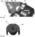
- FIG. 2A illustrates that the front of the container 5 comprises a frame 17, moulded integrally in one piece with the foremost side wall 4'.
- the frame 17 extends outwardly from the foremost side wall 4' and forms a mechanical basis for holding the valve arrangement 14.
- the valve arrangement 14 toggles between closing and opening an outlet channel 15 of the water outlet 13.
- a platform 16 for example a curved platform, as illustrated, which is arranged below the outlet channel 15 and which extends farther from the foremost side wall 4' than the outlet channel 15. From the platform 16, water is dispensed to the user.
- the platform 16 is illustrated as a part of the frame 17, which is, therefore, simple in construction and yields a high mechanical stability.
- a profile 18 which is used as a roof above the outlet channel 15 for preventing water to flow upwards and for guiding the water downwards towards the platform 16.
- the profile 18 extends between opposite sides of the frame 17.
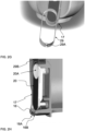
- FIG. 2B illustrates a valve arrangement 14 mounted to the frame 17, where the walls of the container 5 and the frame 17 are moulded in a transparent polymer material.
- the valve arrangement 14 is simple in its construction and comprises in the shown embodiment only three parts, namely a lever 20, a valve member 19, and a helical spring 22.
- the lever 20 comprises a hinge profile 21 on either longitudinal side of the lever 20.
- the hinge profile 21 comprises a protrusion 21C that cooperates with a corresponding opening 17A in the frame 17 for rotational movement of the hinge profile 21 around an axis extending through the openings 17A of the two sides of the frame 17.
- the hinge profiles 21 are slightly pressed towards each other so that the hinge profiles 21 with the protrusions 21C fit in into the space defined by the sides of the frame 17, and the protrusions 21C snap into the cooperating openings 17C.
- FIG. 2C illustrates sectional view through the frame 17 and the lever 20 as well as the spring 22 and the valve member 19.
- the drawing illustrates that not only the profile 18 that creates a roof over the outlet channel 15 prevents water from flowing upwards along the lever 20, but that also the valve member 19 with its upper cylindrical part 19A covers the area above the outlet channel and captures water and guides it downwards to the platform 16.
- a bulb-formed resilient part 19B forms a gasket against the downstream end 15B of the outlet channel 15.
- FIG. 2D shows a perspective view of the valve member 19, showing the cylindrical part 19A that extends over an angular span in the range of 180-270°, which is sufficient as a good barrier for preventing water from flowing upwards.
- FIG. 2E and FIG. 2F illustrate the valve member 19 and its mounting in a detailed image.
- the valve member 19 comprises a notch 19C fitting with a corresponding protrusion 25A on the retainer 25 onto which the resilient valve member 19 is mounted by pressing the resilient elastomeric valve member 19 over the cylindrical edge of the retainer 25.
- the cooperation of the groove 19C and the retainer protrusion 25A assures that the valve member 19 is mounted in a correct orientation.
- FIG. 2G illustrates a cover 19 for the frame 17, where the cover 29 is pushed over the frame 17 and held in place.
- a slit 29A in the cover 29 eases mounting.
- FIG. 2H illustrates a cover 29, which comprises an edge 29B at it upper side in order to make it easier for the user to operate the valve arrangement 14. A user would, thus, place one or two fingers behind the upper edge 29B and press with the thumb against the first end (20A) of the lever 20.
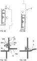
- FIG. 3A illustrates a first principle for the valve arrangement 14 where, instead of the upper edge 29B of the cover 29, there is such an edge 17B for ease of operation integrated in the frame 17 itself.
- the valve arrangement 14 comprises a valve member 19 fastened to the second end of a lever 20 that has a hinged profile 21 and is pre-stressed by a helical coil spring 22 into its closed position.
- the valve member 19 closes the downstream end 15B of the outlet channel 15.
- the spring 22 is located between the hinged profile 21 and the first end (20A) of the lever 20 and compressed in order to exert force on the first end (20A) of the lever 20 by expansion of the spring 22. The expansion force of the spring presses the valve member 19 against the downstream end 15B of the outlet channel 15.
- FIG. 3B illustrates the functioning of the first principle for the valve arrangement 14 of FIG. 3A in that a manual push with a finger, for example thumb, against the upper, first end (20A) of the lever 20 removes the valve member 19 from the downstream end 15B of the outlet channel 15, so that water can flow unhindered through the outlet channel 15 and down onto the platform 16, as illustrated by an arrow 27.
- FIG. 3B show a further feature in addition to the features in FIG. 3A , namely a protrusion 17C on the frame 17, where the protrusion 17C in cooperation with the first end (20A) of the lever 20 forms a snap holder when the second end (20B) of the lever 20 is resiliently pressed under the protrusion 23 by manual force, and where the protrusion 23 holds the lever 20 in the valve-open orientation because the force of the spring 22 is not sufficient for returning the lever 20 pass the protrusion 23.
- An additional manual press on the first end (20B) of the lever 20 is necessary in order to close the valve arrangement 14 again.
- FIG. 3C illustrates an alternative to the embodiment in FIG. 3B in which a magnet 24 is used as an alternative to the protrusion 23, and where the magnetic force is sufficiently strong to counteract the force of the spring 22 and hold the lever 20 in place when the first end (20A) of the lever 20 is attached to the magnet 24.
- FIG. 3D shows a further alternative feature in addition to the features in FIG. 3A , namely a snap holder 23 at the hinged profile 21.
- FIG. 3E illustrates an alternative embodiment, where a spring 30 is connecting a holding point 28 on the foremost side wall 4' of the container 5 with an angled arm 21B of the hinge profile 21 in a knee-joint configuration.
- the holding spring 30 In the open configuration, as shown, the holding spring 30 is compressed and exerts an expanding, pushing force in order to hold the lever 20 in an open state of the valve arrangement.
- the holding spring 30 is first further compressed, until the spring 30 in upward motion passes a dead point line 28A, after which is expands again during further manual pushing of the second end (20A) of the lever 20, after which that the holding spring 30 then holds the lever 20 in an orientation where the lever keeps the valve arrangement 14 in an closing state.
- FIG. 4A illustrates a second principle for the valve arrangement 14.
- the valve arrangement 14 comprises a valve member 19 connected to the end of a stem 31 that is attached with its one end to the second end (20B) of the lever 20.
- the lever 20 is hinged in a hinged profile 21 and pre-stressed by a helical coil spring 22 into its closed position, where the valve member 19 closes the outlet channel 15.
- the valve member closes the upstream end 15A of the outlet channel 15.
- the spring 22 is located between the hinge profile 21 and the second end (20B) of the lever 20 and compressed in order to exert force on the second end (20B) of the lever 20 by extension of the spring.
- FIG. 4B shows a further feature in addition to the features in FIG. 4A , namely a snap holder 26 at the hinged profile 21.
- FIG. 4C illustrates an alternative embodiment, where a spring 30 is connecting a holding point 28 on the foremost side wall 4' of the container 5 with an angled arm 21B of the hinge 21 in a knee-joint configuration.
- the holding spring 30 is compressed when the lever 20 holds the valve arrangement 14 in the closed state.
- the holding spring 30 is first compressed, until the spring passes a dead point line 28A, after which is expands during further manual pulling of the first end (20A) of the lever 20, so that the holding spring 30 then holds the lever 20 in an orientation where the pre-stressed lever 20 keeps the valve arrangement 14 in an open state.
- a manual pushing force is necessary at the first end (20A) of the lever 20 in order to bring the lever 20 into the orientation where the lever 20 holds the valve arrangement 14 in a closed state.
- FIG. 5 illustrates an alternative embodiment for a lever 20, in which a leaf spring 20C is integrated as part of the lever 20 material.
- the leaf spring 20C has a similar function as the helical coil spring 22 explained above.
- the lever 20 was held by its hinge profiles 21 inside the frame 17.
- the valve member 19 and the lever 20 are integrated in a valve insert unit 33, which is mounted, for example pressed, into the frame 17.
- a gasket is used between the downstream end 15B of the outlet channel 15 and the valve insert unit 32.
- FIG. 7 also illustrates a valve insert unit 32, resembling the lever and valve principle of FIG. 4A .
- FIG. 8 illustrates a valve insert unit 32 which uses a different principle for the lever action in that the lever 20 has a central joint 20D and two hinge profiles 21 on either longitudinal edge of the lever 20. Pull at the first end 21A of the lever 20 results in a motion of the second end (20B) in the same direction.
- FIG. 9A and FIG. 9B illustrate mounting principles of the valve insert unit 32.
- the valve insert unit 32 is pushed into the frame 17 in a lateral direction
- the valve insert unit 32 is pushed into the frame 17 in a direction parallel with the foremost side wall 4'.
- the latter requires a slight modification of the frame 17 as compared to the embodiments above.
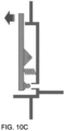
- FIG. 10A illustrates an enlarged view of a valve 34 that is mounted in the foremost side wall 4'.
- the valve 34 comprises a valve stem 31, around which an O-ring 34A is provided for tightening against the upstream end 15A of the outlet channel 15. Pushing against the head 34C of the valve 34 will move the O-ring 34A into the container 5 and away from the upstream end 15A of the outlet channel 15 so that water can flow through the outlet channel 15.
- the O-ring 34A in cooperation with the stem 31 cover the entrance to the outlet channel 15 at its upstream end 15A and therefore constitute a closing valve member 19, taking a role similarly to the one that was discussed above in relation to FIG. 2 .
- FIG. 10B illustrates a slightly different valve arrangement where the valve is closer to the bottom 3 of the container 5 in order to make sure that substantially all water can be emptied through the valve 34.
- FIG. 10C illustrates a lever 20 that can be used to push the head 34C of the valve of FIG. 10 inwards. Notice that the valve itself is not shown in FIG. 10C for simplicity, however, the lever can be used for both valve arrangements of FIG. 10A and FIG. 10B .
Landscapes
- Engineering & Computer Science (AREA)
- Mechanical Engineering (AREA)
- Organic Chemistry (AREA)
- Environmental & Geological Engineering (AREA)
- Water Supply & Treatment (AREA)
- Chemical & Material Sciences (AREA)
- Life Sciences & Earth Sciences (AREA)
- Hydrology & Water Resources (AREA)
- Devices For Dispensing Beverages (AREA)
- Containers And Packaging Bodies Having A Special Means To Remove Contents (AREA)
- Thermally Insulated Containers For Foods (AREA)
- Cookers (AREA)
- Mechanically-Actuated Valves (AREA)
Applications Claiming Priority (2)
| Application Number | Priority Date | Filing Date | Title |
|---|---|---|---|
| US202063005084P | 2020-04-03 | 2020-04-03 | |
| PCT/EP2021/057840 WO2021198042A1 (en) | 2020-04-03 | 2021-03-25 | Water container with manual dispensing valve |
Publications (3)
| Publication Number | Publication Date |
|---|---|
| EP4126752A1 EP4126752A1 (en) | 2023-02-08 |
| EP4126752B1 true EP4126752B1 (en) | 2024-01-03 |
| EP4126752C0 EP4126752C0 (en) | 2024-01-03 |
Family
ID=75377732
Family Applications (1)
| Application Number | Title | Priority Date | Filing Date |
|---|---|---|---|
| EP21716297.3A Active EP4126752B1 (en) | 2020-04-03 | 2021-03-25 | Water container with manual dispensing valve |
Country Status (9)
| Country | Link |
|---|---|
| US (2) | US11884533B2 (pl) |
| EP (1) | EP4126752B1 (pl) |
| KR (1) | KR102903878B1 (pl) |
| CN (2) | CN115667127B (pl) |
| CA (1) | CA3173774A1 (pl) |
| ES (1) | ES2975894T3 (pl) |
| MX (1) | MX2022012098A (pl) |
| PL (1) | PL4126752T3 (pl) |
| WO (1) | WO2021198042A1 (pl) |
Families Citing this family (4)
| Publication number | Priority date | Publication date | Assignee | Title |
|---|---|---|---|---|
| US12318720B2 (en) * | 2017-04-03 | 2025-06-03 | Wellspringpure, Llc | Filter systems and related methods |
| US11872506B2 (en) * | 2018-07-07 | 2024-01-16 | Paragon Water Systems, Inc. | Water filter cartridge having an air vent |
| US11884533B2 (en) * | 2020-04-03 | 2024-01-30 | Lifestraw Sàrl | Water container with manual dispensing valve |
| USD1113320S1 (en) * | 2024-07-31 | 2026-02-17 | Lifestraw Sàrl | Water filter jug |
Citations (1)
| Publication number | Priority date | Publication date | Assignee | Title |
|---|---|---|---|---|
| EP2679545B1 (de) * | 2012-06-26 | 2017-12-13 | WMF Württembergische Metallwarenfabrik Aktiengesellschaft | Wasserreinigung Maschine |
Family Cites Families (12)
| Publication number | Priority date | Publication date | Assignee | Title |
|---|---|---|---|---|
| EP0165494A1 (de) * | 1984-05-24 | 1985-12-27 | EMIDE-METALLINDUSTRIE Gebr. Streicher | Küchengerät |
| US4905743A (en) * | 1988-11-14 | 1990-03-06 | Gray Alden J | Faucet for filling maple syrup jugs and the like |
| US5927557A (en) * | 1996-06-11 | 1999-07-27 | Busick; Louis M. | Reservoir and faucet assembly for a water cooler |
| US5944225A (en) * | 1997-09-04 | 1999-08-31 | The Meyer Company | Insulated faucet for dispensing hot liquids |
| US5971218A (en) * | 1998-03-12 | 1999-10-26 | Cambro Manufacturing Company | Food and beverage dispenser with a dynamic seal |
| US8448564B2 (en) | 2006-05-20 | 2013-05-28 | Bunn-O-Matic Corporation | Side exit faucet server |
| US20160244312A1 (en) * | 2015-02-21 | 2016-08-25 | Kenneth John Gallagher | Counter Water Bottle Dispenser |
| KR20180010193A (ko) | 2015-05-21 | 2018-01-30 | 액세스 비지니스 그룹 인터내셔날 엘엘씨 | 휴대용 수처리 시스템 |
| KR101772528B1 (ko) * | 2015-08-21 | 2017-08-29 | 엘지전자 주식회사 | 정수기 |
| DE102016221210A1 (de) * | 2016-10-27 | 2018-05-03 | BSH Hausgeräte GmbH | Behälter-Ventil-Baugruppe für einen Getränkedispenser |
| US10962139B2 (en) | 2018-02-01 | 2021-03-30 | Kohler Co. | Handwashing valve structure |
| US11884533B2 (en) * | 2020-04-03 | 2024-01-30 | Lifestraw Sàrl | Water container with manual dispensing valve |
-
2021
- 2021-03-25 US US17/995,358 patent/US11884533B2/en active Active
- 2021-03-25 EP EP21716297.3A patent/EP4126752B1/en active Active
- 2021-03-25 WO PCT/EP2021/057840 patent/WO2021198042A1/en not_active Ceased
- 2021-03-25 ES ES21716297T patent/ES2975894T3/es active Active
- 2021-03-25 MX MX2022012098A patent/MX2022012098A/es unknown
- 2021-03-25 KR KR1020227035892A patent/KR102903878B1/ko active Active
- 2021-03-25 CA CA3173774A patent/CA3173774A1/en active Pending
- 2021-03-25 CN CN202180037487.9A patent/CN115667127B/zh active Active
- 2021-03-25 PL PL21716297.3T patent/PL4126752T3/pl unknown
- 2021-03-25 CN CN202511082085.7A patent/CN120664488A/zh active Pending
-
2023
- 2023-11-30 US US18/525,022 patent/US12600616B2/en active Active
Patent Citations (1)
| Publication number | Priority date | Publication date | Assignee | Title |
|---|---|---|---|---|
| EP2679545B1 (de) * | 2012-06-26 | 2017-12-13 | WMF Württembergische Metallwarenfabrik Aktiengesellschaft | Wasserreinigung Maschine |
Also Published As
| Publication number | Publication date |
|---|---|
| CA3173774A1 (en) | 2021-10-07 |
| KR102903878B1 (ko) | 2025-12-26 |
| KR20220162135A (ko) | 2022-12-07 |
| CN115667127B (zh) | 2025-08-19 |
| CN115667127A (zh) | 2023-01-31 |
| US20230150810A1 (en) | 2023-05-18 |
| ES2975894T3 (es) | 2024-07-17 |
| WO2021198042A1 (en) | 2021-10-07 |
| US12600616B2 (en) | 2026-04-14 |
| US11884533B2 (en) | 2024-01-30 |
| WO2021198042A9 (en) | 2021-12-23 |
| PL4126752T3 (pl) | 2024-07-29 |
| EP4126752A1 (en) | 2023-02-08 |
| US20240351856A1 (en) | 2024-10-24 |
| EP4126752C0 (en) | 2024-01-03 |
| CN120664488A (zh) | 2025-09-19 |
| MX2022012098A (es) | 2023-03-03 |
Similar Documents
| Publication | Publication Date | Title |
|---|---|---|
| EP4126752B1 (en) | Water container with manual dispensing valve | |
| US6936161B2 (en) | Fluid filter apparatus | |
| KR100847208B1 (ko) | 휴대용 정수기 | |
| US7237569B2 (en) | Ball check valve | |
| US4986308A (en) | Switching microelectrovalve having a single membrane | |
| KR101945790B1 (ko) | 자동 드레인 배출 장치 | |
| US9555938B2 (en) | Liquid container | |
| US10258911B2 (en) | Portable water purifier | |
| CA2462197A1 (en) | Fuel dispenser filter with removable filter media | |
| EP3747795B1 (en) | Discharge device for discharging liquid content in tube container in droplet form | |
| KR20220019688A (ko) | 음료 보틀 | |
| US20080185404A1 (en) | Beverage server | |
| WO2023034841A1 (en) | Beverage container system with interchangeable inserts | |
| EP3693075A1 (en) | Pressure relief cover assembly | |
| CN217078998U (zh) | 一种过滤装置及智能马桶 | |
| CA2499990C (en) | Ball check valve | |
| JP2002156095A (ja) | ドレン排出装置 | |
| JPH0526183U (ja) | 浄水器 | |
| JP2569491Y2 (ja) | 浄水器 | |
| JPH0525754Y2 (pl) | ||
| JPS596740Y2 (ja) | 液体容器の注出口装置 | |
| JP2001212018A (ja) | 流路切換器およびシャワーヘッド | |
| JPH0526185U (ja) | 浄水器 | |
| JPH0526184U (ja) | 浄水器 | |
| JPH10205945A (ja) | 自動製氷機付き冷蔵庫の給水タンク |
Legal Events
| Date | Code | Title | Description |
|---|---|---|---|
| STAA | Information on the status of an ep patent application or granted ep patent |
Free format text: STATUS: UNKNOWN |
|
| STAA | Information on the status of an ep patent application or granted ep patent |
Free format text: STATUS: THE INTERNATIONAL PUBLICATION HAS BEEN MADE |
|
| PUAI | Public reference made under article 153(3) epc to a published international application that has entered the european phase |
Free format text: ORIGINAL CODE: 0009012 |
|
| STAA | Information on the status of an ep patent application or granted ep patent |
Free format text: STATUS: REQUEST FOR EXAMINATION WAS MADE |
|
| 17P | Request for examination filed |
Effective date: 20221026 |
|
| AK | Designated contracting states |
Kind code of ref document: A1 Designated state(s): AL AT BE BG CH CY CZ DE DK EE ES FI FR GB GR HR HU IE IS IT LI LT LU LV MC MK MT NL NO PL PT RO RS SE SI SK SM TR |
|
| DAV | Request for validation of the european patent (deleted) | ||
| DAX | Request for extension of the european patent (deleted) | ||
| GRAP | Despatch of communication of intention to grant a patent |
Free format text: ORIGINAL CODE: EPIDOSNIGR1 |
|
| STAA | Information on the status of an ep patent application or granted ep patent |
Free format text: STATUS: GRANT OF PATENT IS INTENDED |
|
| INTG | Intention to grant announced |
Effective date: 20230908 |
|
| GRAS | Grant fee paid |
Free format text: ORIGINAL CODE: EPIDOSNIGR3 |
|
| GRAA | (expected) grant |
Free format text: ORIGINAL CODE: 0009210 |
|
| STAA | Information on the status of an ep patent application or granted ep patent |
Free format text: STATUS: THE PATENT HAS BEEN GRANTED |
|
| AK | Designated contracting states |
Kind code of ref document: B1 Designated state(s): AL AT BE BG CH CY CZ DE DK EE ES FI FR GB GR HR HU IE IS IT LI LT LU LV MC MK MT NL NO PL PT RO RS SE SI SK SM TR |
|
| REG | Reference to a national code |
Ref country code: GB Ref legal event code: FG4D |
|
| REG | Reference to a national code |
Ref country code: CH Ref legal event code: EP |
|
| REG | Reference to a national code |
Ref country code: DE Ref legal event code: R096 Ref document number: 602021008357 Country of ref document: DE |
|
| REG | Reference to a national code |
Ref country code: IE Ref legal event code: FG4D |
|
| U01 | Request for unitary effect filed |
Effective date: 20240124 |
|
| U07 | Unitary effect registered |
Designated state(s): AT BE BG DE DK EE FI FR IT LT LU LV MT NL PT SE SI Effective date: 20240205 |
|
| U20 | Renewal fee for the european patent with unitary effect paid |
Year of fee payment: 4 Effective date: 20240212 |
|
| PG25 | Lapsed in a contracting state [announced via postgrant information from national office to epo] |
Ref country code: IS Free format text: LAPSE BECAUSE OF FAILURE TO SUBMIT A TRANSLATION OF THE DESCRIPTION OR TO PAY THE FEE WITHIN THE PRESCRIBED TIME-LIMIT Effective date: 20240503 |
|
| PG25 | Lapsed in a contracting state [announced via postgrant information from national office to epo] |
Ref country code: GR Free format text: LAPSE BECAUSE OF FAILURE TO SUBMIT A TRANSLATION OF THE DESCRIPTION OR TO PAY THE FEE WITHIN THE PRESCRIBED TIME-LIMIT Effective date: 20240404 |
|
| REG | Reference to a national code |
Ref country code: ES Ref legal event code: FG2A Ref document number: 2975894 Country of ref document: ES Kind code of ref document: T3 Effective date: 20240717 |
|
| PG25 | Lapsed in a contracting state [announced via postgrant information from national office to epo] |
Ref country code: HR Free format text: LAPSE BECAUSE OF FAILURE TO SUBMIT A TRANSLATION OF THE DESCRIPTION OR TO PAY THE FEE WITHIN THE PRESCRIBED TIME-LIMIT Effective date: 20240103 Ref country code: RS Free format text: LAPSE BECAUSE OF FAILURE TO SUBMIT A TRANSLATION OF THE DESCRIPTION OR TO PAY THE FEE WITHIN THE PRESCRIBED TIME-LIMIT Effective date: 20240403 |
|
| PG25 | Lapsed in a contracting state [announced via postgrant information from national office to epo] |
Ref country code: CZ Free format text: LAPSE BECAUSE OF FAILURE TO SUBMIT A TRANSLATION OF THE DESCRIPTION OR TO PAY THE FEE WITHIN THE PRESCRIBED TIME-LIMIT Effective date: 20240103 |
|
| PG25 | Lapsed in a contracting state [announced via postgrant information from national office to epo] |
Ref country code: RS Free format text: LAPSE BECAUSE OF FAILURE TO SUBMIT A TRANSLATION OF THE DESCRIPTION OR TO PAY THE FEE WITHIN THE PRESCRIBED TIME-LIMIT Effective date: 20240403 Ref country code: NO Free format text: LAPSE BECAUSE OF FAILURE TO SUBMIT A TRANSLATION OF THE DESCRIPTION OR TO PAY THE FEE WITHIN THE PRESCRIBED TIME-LIMIT Effective date: 20240403 Ref country code: IS Free format text: LAPSE BECAUSE OF FAILURE TO SUBMIT A TRANSLATION OF THE DESCRIPTION OR TO PAY THE FEE WITHIN THE PRESCRIBED TIME-LIMIT Effective date: 20240503 Ref country code: HR Free format text: LAPSE BECAUSE OF FAILURE TO SUBMIT A TRANSLATION OF THE DESCRIPTION OR TO PAY THE FEE WITHIN THE PRESCRIBED TIME-LIMIT Effective date: 20240103 Ref country code: GR Free format text: LAPSE BECAUSE OF FAILURE TO SUBMIT A TRANSLATION OF THE DESCRIPTION OR TO PAY THE FEE WITHIN THE PRESCRIBED TIME-LIMIT Effective date: 20240404 Ref country code: CZ Free format text: LAPSE BECAUSE OF FAILURE TO SUBMIT A TRANSLATION OF THE DESCRIPTION OR TO PAY THE FEE WITHIN THE PRESCRIBED TIME-LIMIT Effective date: 20240103 |
|
| REG | Reference to a national code |
Ref country code: DE Ref legal event code: R097 Ref document number: 602021008357 Country of ref document: DE |
|
| PG25 | Lapsed in a contracting state [announced via postgrant information from national office to epo] |
Ref country code: SM Free format text: LAPSE BECAUSE OF FAILURE TO SUBMIT A TRANSLATION OF THE DESCRIPTION OR TO PAY THE FEE WITHIN THE PRESCRIBED TIME-LIMIT Effective date: 20240103 |
|
| PG25 | Lapsed in a contracting state [announced via postgrant information from national office to epo] |
Ref country code: SK Free format text: LAPSE BECAUSE OF FAILURE TO SUBMIT A TRANSLATION OF THE DESCRIPTION OR TO PAY THE FEE WITHIN THE PRESCRIBED TIME-LIMIT Effective date: 20240103 |
|
| PG25 | Lapsed in a contracting state [announced via postgrant information from national office to epo] |
Ref country code: SM Free format text: LAPSE BECAUSE OF FAILURE TO SUBMIT A TRANSLATION OF THE DESCRIPTION OR TO PAY THE FEE WITHIN THE PRESCRIBED TIME-LIMIT Effective date: 20240103 Ref country code: SK Free format text: LAPSE BECAUSE OF FAILURE TO SUBMIT A TRANSLATION OF THE DESCRIPTION OR TO PAY THE FEE WITHIN THE PRESCRIBED TIME-LIMIT Effective date: 20240103 Ref country code: RO Free format text: LAPSE BECAUSE OF FAILURE TO SUBMIT A TRANSLATION OF THE DESCRIPTION OR TO PAY THE FEE WITHIN THE PRESCRIBED TIME-LIMIT Effective date: 20240103 |
|
| PLBE | No opposition filed within time limit |
Free format text: ORIGINAL CODE: 0009261 |
|
| STAA | Information on the status of an ep patent application or granted ep patent |
Free format text: STATUS: NO OPPOSITION FILED WITHIN TIME LIMIT |
|
| PG25 | Lapsed in a contracting state [announced via postgrant information from national office to epo] |
Ref country code: MC Free format text: LAPSE BECAUSE OF FAILURE TO SUBMIT A TRANSLATION OF THE DESCRIPTION OR TO PAY THE FEE WITHIN THE PRESCRIBED TIME-LIMIT Effective date: 20240103 |
|
| PG25 | Lapsed in a contracting state [announced via postgrant information from national office to epo] |
Ref country code: MC Free format text: LAPSE BECAUSE OF FAILURE TO SUBMIT A TRANSLATION OF THE DESCRIPTION OR TO PAY THE FEE WITHIN THE PRESCRIBED TIME-LIMIT Effective date: 20240103 |
|
| 26N | No opposition filed |
Effective date: 20241007 |
|
| U20 | Renewal fee for the european patent with unitary effect paid |
Year of fee payment: 5 Effective date: 20250120 |
|
| PGFP | Annual fee paid to national office [announced via postgrant information from national office to epo] |
Ref country code: PL Payment date: 20250221 Year of fee payment: 5 |
|
| PGFP | Annual fee paid to national office [announced via postgrant information from national office to epo] |
Ref country code: ES Payment date: 20250401 Year of fee payment: 5 |
|
| PGFP | Annual fee paid to national office [announced via postgrant information from national office to epo] |
Ref country code: CH Payment date: 20250401 Year of fee payment: 5 |
|
| PG25 | Lapsed in a contracting state [announced via postgrant information from national office to epo] |
Ref country code: CY Free format text: LAPSE BECAUSE OF FAILURE TO SUBMIT A TRANSLATION OF THE DESCRIPTION OR TO PAY THE FEE WITHIN THE PRESCRIBED TIME-LIMIT; INVALID AB INITIO Effective date: 20210325 |
|
| PG25 | Lapsed in a contracting state [announced via postgrant information from national office to epo] |
Ref country code: HU Free format text: LAPSE BECAUSE OF FAILURE TO SUBMIT A TRANSLATION OF THE DESCRIPTION OR TO PAY THE FEE WITHIN THE PRESCRIBED TIME-LIMIT; INVALID AB INITIO Effective date: 20210325 |
|
| PG25 | Lapsed in a contracting state [announced via postgrant information from national office to epo] |
Ref country code: TR Free format text: LAPSE BECAUSE OF FAILURE TO SUBMIT A TRANSLATION OF THE DESCRIPTION OR TO PAY THE FEE WITHIN THE PRESCRIBED TIME-LIMIT Effective date: 20240103 |
|
| U20 | Renewal fee for the european patent with unitary effect paid |
Year of fee payment: 6 Effective date: 20260112 |
|
| REG | Reference to a national code |
Ref country code: CH Ref legal event code: U11 Free format text: ST27 STATUS EVENT CODE: U-0-0-U10-U11 (AS PROVIDED BY THE NATIONAL OFFICE) Effective date: 20260401 |
|
| PGFP | Annual fee paid to national office [announced via postgrant information from national office to epo] |
Ref country code: GB Payment date: 20260330 Year of fee payment: 6 |
|
| PGFP | Annual fee paid to national office [announced via postgrant information from national office to epo] |
Ref country code: IE Payment date: 20260326 Year of fee payment: 6 |