EP4126616B1 - Verfahren sowie kraftfahrzeug - Google Patents
Verfahren sowie kraftfahrzeug Download PDFInfo
- Publication number
- EP4126616B1 EP4126616B1 EP21704491.6A EP21704491A EP4126616B1 EP 4126616 B1 EP4126616 B1 EP 4126616B1 EP 21704491 A EP21704491 A EP 21704491A EP 4126616 B1 EP4126616 B1 EP 4126616B1
- Authority
- EP
- European Patent Office
- Prior art keywords
- torque
- engine
- brake
- rear wheel
- braking
- Prior art date
- Legal status (The legal status is an assumption and is not a legal conclusion. Google has not performed a legal analysis and makes no representation as to the accuracy of the status listed.)
- Active
Links
Images

Classifications
-
- B—PERFORMING OPERATIONS; TRANSPORTING
- B60—VEHICLES IN GENERAL
- B60T—VEHICLE BRAKE CONTROL SYSTEMS OR PARTS THEREOF; BRAKE CONTROL SYSTEMS OR PARTS THEREOF, IN GENERAL; ARRANGEMENT OF BRAKING ELEMENTS ON VEHICLES IN GENERAL; PORTABLE DEVICES FOR PREVENTING UNWANTED MOVEMENT OF VEHICLES; VEHICLE MODIFICATIONS TO FACILITATE COOLING OF BRAKES
- B60T8/00—Arrangements for adjusting wheel-braking force to meet varying vehicular or ground-surface conditions, e.g. limiting or varying distribution of braking force
- B60T8/17—Using electrical or electronic regulation means to control braking
- B60T8/1701—Braking or traction control means specially adapted for particular types of vehicles
- B60T8/1706—Braking or traction control means specially adapted for particular types of vehicles for single-track vehicles, e.g. motorcycles
-
- B—PERFORMING OPERATIONS; TRANSPORTING
- B60—VEHICLES IN GENERAL
- B60T—VEHICLE BRAKE CONTROL SYSTEMS OR PARTS THEREOF; BRAKE CONTROL SYSTEMS OR PARTS THEREOF, IN GENERAL; ARRANGEMENT OF BRAKING ELEMENTS ON VEHICLES IN GENERAL; PORTABLE DEVICES FOR PREVENTING UNWANTED MOVEMENT OF VEHICLES; VEHICLE MODIFICATIONS TO FACILITATE COOLING OF BRAKES
- B60T8/00—Arrangements for adjusting wheel-braking force to meet varying vehicular or ground-surface conditions, e.g. limiting or varying distribution of braking force
- B60T8/17—Using electrical or electronic regulation means to control braking
- B60T8/1755—Brake regulation specially adapted to control the stability of the vehicle, e.g. taking into account yaw rate or transverse acceleration in a curve
-
- B—PERFORMING OPERATIONS; TRANSPORTING
- B60—VEHICLES IN GENERAL
- B60T—VEHICLE BRAKE CONTROL SYSTEMS OR PARTS THEREOF; BRAKE CONTROL SYSTEMS OR PARTS THEREOF, IN GENERAL; ARRANGEMENT OF BRAKING ELEMENTS ON VEHICLES IN GENERAL; PORTABLE DEVICES FOR PREVENTING UNWANTED MOVEMENT OF VEHICLES; VEHICLE MODIFICATIONS TO FACILITATE COOLING OF BRAKES
- B60T8/00—Arrangements for adjusting wheel-braking force to meet varying vehicular or ground-surface conditions, e.g. limiting or varying distribution of braking force
- B60T8/26—Arrangements for adjusting wheel-braking force to meet varying vehicular or ground-surface conditions, e.g. limiting or varying distribution of braking force characterised by producing differential braking between front and rear wheels
- B60T8/261—Arrangements for adjusting wheel-braking force to meet varying vehicular or ground-surface conditions, e.g. limiting or varying distribution of braking force characterised by producing differential braking between front and rear wheels specially adapted for use in motorcycles
-
- B—PERFORMING OPERATIONS; TRANSPORTING
- B60—VEHICLES IN GENERAL
- B60W—CONJOINT CONTROL OF VEHICLE SUB-UNITS OF DIFFERENT TYPE OR DIFFERENT FUNCTION; CONTROL SYSTEMS SPECIALLY ADAPTED FOR HYBRID VEHICLES; ROAD VEHICLE DRIVE CONTROL SYSTEMS FOR PURPOSES NOT RELATED TO THE CONTROL OF A PARTICULAR SUB-UNIT
- B60W10/00—Conjoint control of vehicle sub-units of different type or different function
- B60W10/04—Conjoint control of vehicle sub-units of different type or different function including control of propulsion units
- B60W10/06—Conjoint control of vehicle sub-units of different type or different function including control of propulsion units including control of combustion engines
-
- B—PERFORMING OPERATIONS; TRANSPORTING
- B60—VEHICLES IN GENERAL
- B60W—CONJOINT CONTROL OF VEHICLE SUB-UNITS OF DIFFERENT TYPE OR DIFFERENT FUNCTION; CONTROL SYSTEMS SPECIALLY ADAPTED FOR HYBRID VEHICLES; ROAD VEHICLE DRIVE CONTROL SYSTEMS FOR PURPOSES NOT RELATED TO THE CONTROL OF A PARTICULAR SUB-UNIT
- B60W10/00—Conjoint control of vehicle sub-units of different type or different function
- B60W10/18—Conjoint control of vehicle sub-units of different type or different function including control of braking systems
- B60W10/184—Conjoint control of vehicle sub-units of different type or different function including control of braking systems with wheel brakes
-
- B—PERFORMING OPERATIONS; TRANSPORTING
- B60—VEHICLES IN GENERAL
- B60W—CONJOINT CONTROL OF VEHICLE SUB-UNITS OF DIFFERENT TYPE OR DIFFERENT FUNCTION; CONTROL SYSTEMS SPECIALLY ADAPTED FOR HYBRID VEHICLES; ROAD VEHICLE DRIVE CONTROL SYSTEMS FOR PURPOSES NOT RELATED TO THE CONTROL OF A PARTICULAR SUB-UNIT
- B60W30/00—Purposes of road vehicle drive control systems not related to the control of a particular sub-unit, e.g. of systems using conjoint control of vehicle sub-units
- B60W30/18—Propelling the vehicle
- B60W30/18009—Propelling the vehicle related to particular drive situations
- B60W30/18109—Braking
-
- B—PERFORMING OPERATIONS; TRANSPORTING
- B60—VEHICLES IN GENERAL
- B60T—VEHICLE BRAKE CONTROL SYSTEMS OR PARTS THEREOF; BRAKE CONTROL SYSTEMS OR PARTS THEREOF, IN GENERAL; ARRANGEMENT OF BRAKING ELEMENTS ON VEHICLES IN GENERAL; PORTABLE DEVICES FOR PREVENTING UNWANTED MOVEMENT OF VEHICLES; VEHICLE MODIFICATIONS TO FACILITATE COOLING OF BRAKES
- B60T2260/00—Interaction of vehicle brake system with other systems
- B60T2260/09—Complex systems; Conjoint control of two or more vehicle active control systems
-
- B—PERFORMING OPERATIONS; TRANSPORTING
- B60—VEHICLES IN GENERAL
- B60T—VEHICLE BRAKE CONTROL SYSTEMS OR PARTS THEREOF; BRAKE CONTROL SYSTEMS OR PARTS THEREOF, IN GENERAL; ARRANGEMENT OF BRAKING ELEMENTS ON VEHICLES IN GENERAL; PORTABLE DEVICES FOR PREVENTING UNWANTED MOVEMENT OF VEHICLES; VEHICLE MODIFICATIONS TO FACILITATE COOLING OF BRAKES
- B60T2270/00—Further aspects of brake control systems not otherwise provided for
- B60T2270/30—ESP control system
- B60T2270/303—Stability control with active acceleration
-
- B—PERFORMING OPERATIONS; TRANSPORTING
- B60—VEHICLES IN GENERAL
- B60T—VEHICLE BRAKE CONTROL SYSTEMS OR PARTS THEREOF; BRAKE CONTROL SYSTEMS OR PARTS THEREOF, IN GENERAL; ARRANGEMENT OF BRAKING ELEMENTS ON VEHICLES IN GENERAL; PORTABLE DEVICES FOR PREVENTING UNWANTED MOVEMENT OF VEHICLES; VEHICLE MODIFICATIONS TO FACILITATE COOLING OF BRAKES
- B60T2270/00—Further aspects of brake control systems not otherwise provided for
- B60T2270/30—ESP control system
- B60T2270/304—ESP control system during driver brake actuation
-
- B—PERFORMING OPERATIONS; TRANSPORTING
- B60—VEHICLES IN GENERAL
- B60W—CONJOINT CONTROL OF VEHICLE SUB-UNITS OF DIFFERENT TYPE OR DIFFERENT FUNCTION; CONTROL SYSTEMS SPECIALLY ADAPTED FOR HYBRID VEHICLES; ROAD VEHICLE DRIVE CONTROL SYSTEMS FOR PURPOSES NOT RELATED TO THE CONTROL OF A PARTICULAR SUB-UNIT
- B60W2300/00—Indexing codes relating to the type of vehicle
- B60W2300/36—Cycles; Motorcycles; Scooters
Definitions
- the invention relates to a method for decelerating a single-track motor vehicle and to a motor vehicle.
- the generic DE 10 2012 222884 A1 describes a process that uses sensors in the two-wheeler to detect an impending or already existing critical driving condition.
- the sideslip angle or a driving condition variable that correlates with the sideslip angle is determined on the basis of sensor data and compared with an assigned limit value. If the sideslip angle or the driving condition variable that correlates with it exceeds the limit value, the torque on at least one vehicle wheel is automatically modified as a countermeasure.
- the DE 10 2008 011 575 A1 , the US 2016/009275 A1 and the DE 10 2016 200 500 A1 discuss further methods for stabilizing a two-wheeler.
- deceleration of a motor vehicle is used to reduce the speed of the vehicle in a controlled manner, for example in order to approach a curve at an appropriate speed.
- Single-track vehicles in particular usually approach bends in a sporty manner.
- This type of slide represents a controlled, deliberate overbraking of the rear wheel, which creates a high level of slip on the rear wheel and reduces its cornering force. The higher the slip, the lower the cornering force and the higher the slip angle (slide).
- the slide can be used to achieve a greater deceleration of the vehicle than with normal braking, for example when braking into a curve. This means that the curve can be braked later and the curve can be negotiated more quickly.
- the object of the invention is to provide a method and a motor vehicle in which a controlled slide can be easily achieved.
- the partial motor torque - in relation to a forward direction of the wheels of the single-track motor vehicle - can be an acceleration torque, i.e. the initial torque of the wheel is increased to the total torque by the motor controlled by the control unit. Accordingly, the value of the partial motor torque is higher after the motor is controlled than before the control.
- the partial engine torque is controlled by an engine drag torque control.
- An effective coupling of the engine and the rear wheel is always present in single-track motor vehicles. Accordingly, no further mechanism needs to be provided to apply the partial engine torque to the rear wheel. Accordingly, the partial engine torque can easily be controlled by the engine drag torque control without the need for additional components and control units.
- the driving maneuver is a controlled overbraking of the rear wheel when braking into a curve, which causes high slip on the rear wheel.
- the cornering force of the rear wheel is reduced and the slip angle of the rear wheel is increased. This allows the vehicle to be decelerated more strongly than with a normal braking process.
- the slip angle of the rear wheel represents a "slide" of the rear wheel.
- the partial brake torque and the partial motor torque can add up to the required total torque.
- the advantages of the braking system (generation of high braking torques) and the motor (high precision and control speed) can be combined to apply exactly the required total torque to the wheel.
- control unit detects before or during the desired driving maneuver that the driver wants to carry out the desired driving maneuver.
- the detection can either take place automatically or be induced manually.
- the automatic detection can be carried out on the basis of various vehicle parameters, such as a current brake pressure on the rear wheel brake and/or the front wheel brake, a current inertial state of the motor vehicle, in particular a current lean angle and a current sideslip angle, the current deceleration and a current speed of the motor vehicle.
- vehicle parameters such as a current brake pressure on the rear wheel brake and/or the front wheel brake, a current inertial state of the motor vehicle, in particular a current lean angle and a current sideslip angle, the current deceleration and a current speed of the motor vehicle.
- control unit can be informed before or during the desired driving maneuver by the driver manually operating a trigger that the desired driving maneuver should be carried out the next time the motor vehicle decelerates or now - when the motor vehicle is currently decelerating.
- the trigger can, for example, be a manual input by the driver on one of the input devices.
- a short manual actuation of the rear brake by the driver can serve as a trigger.
- the brake control can represent the control of the ABS. Therefore, no additional control for the ABS needs to be provided, which saves installation space, manufacturing effort and costs.
- the brake control and the engine control can be linked to each other in terms of signals, so that information or data recorded by a sensor can be exchanged between the brake control and the engine control, particularly bidirectionally. In this way, the brake system and the engine can be controlled independently of each other.
- the motor is controlled depending on the partial braking torque generated by the braking system, so that the partial motor torque generated by the motor is dependent on the partial braking torque.
- the brake system can be controlled fully automatically with the required target brake pressure to achieve a controlled slide by the control unit, in particular by the brake control. This makes initiating the controlled slide much easier, since the target brake pressure is generated without the driver of the vehicle having to operate the rear brake himself.
- the braking system in particular the rear wheel brake
- the brake control representing a brake pressure limitation of the rear wheel brake, by means of which the braking pressure applied by the driver is set to the target braking pressure, in particular reduced.
- the braking pressure applied by the driver can be reduced to the target braking pressure by controlling the braking system via the control unit, in particular the brake control.
- the control unit, in particular the brake control thus limits, taking into account various parameters, the braking pressure applied by the driver of the motor vehicle to the target braking pressure that is necessary to initiate the controlled slide of the wheel. This sub-function relieves the driver of the correct dosage of the rear wheel brake, since he only has to operate it strongly, while the brake control sets the actually necessary target braking pressure. This prevents excessive overbraking and makes initiating the controlled slide much easier.
- the torque of the motor is increased to the target torque.
- the motor torque is increased, a larger torque range is available than when the motor torque is reduced. Accordingly, it is advantageous if the partial brake torque is slightly below the desired total torque and the partial motor torque is used to compensate for the current torque resulting from the partial brake torque. Torque at the rear wheel is increased very precisely to the desired total torque.
- the engine is regulated to the determined target torque by controlling the entire engine, individual cylinders and/or individual cylinder banks of the engine. In this way, the engine can be regulated to the determined target torque in a way that is adapted to the current state of the vehicle and therefore efficient.
- the total torque, the partial brake torque, in particular the target brake pressure, and/or the partial engine torque, in particular the target torque is determined on the basis of a current steering angle, a current wheel speed of a front wheel, a current wheel speed of the rear wheel, a current vehicle speed, a current slip of the front wheel, a current slip of the rear wheel, a current inertial state, in particular a current lean angle and/or a current sideslip angle of the motor vehicle, a selected driving mode and/or a brake pressure applied by the driver, in particular on the front wheel.
- the total torque suitable for the current state of the motor vehicle can be determined, which is necessary to initiate a stable, controlled slide of the rear wheel.
- the inertial state may include a tilt, a slip angle and/or the like.
- the partial braking torque in particular the target braking pressure
- the deceleration is determined on the one hand on the basis of the inertial state and on the other hand from the brake pressure applied to the front wheel.
- the driver is relieved of the correct dosage of the rear wheel brake, as he only has to apply it strongly while the control unit, in particular the brake control and the ABS, sets the actually required partial brake torque, in particular the actually required target brake pressure.
- the partial engine torque in particular the target torque
- the engine control in particular an engine drag torque control, determines the slip on the rear wheel and sets it to a target value by increasing the engine torque.
- the target value is determined on the one hand from the inertial state, in particular from the incline and/or the sideslip angle, and on the other hand from the deceleration and/or the vehicle speed of the motor vehicle.
- various settings for example wheel properties such as the tire type, and/or driving modes, for example sport mode with particularly pronounced sliding behavior, which influence the deceleration behavior of the vehicle, can be used to determine the total torque or the partial torques.
- a single-track motor vehicle in particular a motorcycle, which has a front wheel and a rear wheel, a braking system with a front wheel brake and a rear wheel brake, an engine, at least one sensor system and a control unit coupled to the braking system, the engine and the sensor system, which is designed to carry out the method described above.
- a single-track motor vehicle has a combined control of the rear wheel torque when the motor vehicle is decelerated, in which a total torque is generated at the rear wheel by a combination of brake-induced partial braking torque at the rear wheel and engine-induced partial motor torque at the rear wheel. This total torque is selected so that the rear wheel is overbraked in a controlled manner and thus a A controlled, stable slide of the rear wheel is initiated, which results in better steering and braking behavior of the vehicle.
- the motor vehicle may additionally have a brake control, in particular with ABS, and an engine control, in particular an engine drag torque control, which may be part of the control unit.
- a brake control in particular with ABS
- an engine control in particular an engine drag torque control
- FIG. 1 a single-track motor vehicle 10 according to the invention with a rear wheel 12 and a rear wheel brake 14 as well as a front wheel 16 and a front wheel brake 18, a motor 20 and a control unit 22 is shown.
- the control unit 22 comprises a motor control 24 coupled to the motor 20 and a brake control 26 coupled to the rear wheel brake 14 and the front wheel brake 18.
- the engine control 24 therefore controls the engine 20 and the brake control 26 therefore controls the rear wheel brake 14 and the front wheel brake 18.
- the rear wheel brake 14 and the front wheel brake 18 together represent a braking system of the motor vehicle 10, which can include an anti-lock braking system (ABS).
- the brake control 26 can also be the control of the ABS.
- the engine control 24 and the brake control 26 can be part of the control unit 22 or each form its own separate control.
- the motor vehicle 10 On the rear wheel 12, the motor vehicle 10 has a rear wheel brake pressure sensor 28 and a rear wheel speed sensor 30.
- the motor vehicle 10 On the front wheel 16, the motor vehicle 10 has a front wheel brake pressure sensor 32 and a front wheel speed sensor 34.
- the motor vehicle 10 has a steering angle sensor system 36 and an inertial measuring sensor system 38.
- the inertial measuring sensor system 38 can, for example, comprise three acceleration sensors and three yaw rate sensors, by means of which, among other things, an inclination and a slip angle of the motor vehicle 10 can be detected.
- the motor vehicle 10 can have one or more user interfaces, for example in the form of an input device 40 or several input devices 40, which is or are in data connection with the control unit 22.
- the desired driving maneuver is a controlled, intentional overbraking of the rear wheel 12, whereby a controlled, stable "slide" of the rear wheel 12 is to be generated in order to achieve a greater deceleration of the motor vehicle than would be possible with a normal braking process.
- the brake control 26 or, more precisely, the brake pressure sensors 28, 32 of the control unit 22 detects a brake pressure D generated by the driver by actuating the rear wheel brake 14 and/or the front wheel brake 18, which leads to a deceleration of the motor vehicle 10.
- the brake pressure D at the rear wheel brake 14 and the brake pressure D at the front wheel brake 18 can be different.
- the control unit 22 can automatically detect, based on various vehicle parameters, that the desired driving maneuver is to be carried out.
- control unit 12 can be informed, before or during the desired driving maneuver, by a manual input on one of the input devices 40 that the desired driving maneuver is to be carried out the next time the motor vehicle 10 decelerates or now.
- control unit 22 determines, based on the detected brake pressure D at the rear wheel brake 14 and/or the front wheel brake 18 as well as further data from the wheel speed sensors 30, 34, the steering angle sensors 36 and the inertial measuring sensors 38, a total torque GM that is necessary at the rear wheel 12 in order to initiate the desired overbraking and thus the slide of the rear wheel 12.
- the basic idea of the method is to generate a part of the necessary total torque GM by the engine control 24 and another part of the necessary total torque GM by the brake control 26.
- a step S1 the driver of the motor vehicle 10 actuates the rear wheel brake 14 and/or the front wheel brake 18 in order to achieve a deceleration of the motor vehicle 10.
- the driver By actuating the rear wheel brake 14 and/or the front wheel brake 18, the driver generates the brake pressure D at the rear wheel brake 14 or at the front wheel brake 18.
- step S2 the control unit 12 recognizes that the driver wants to perform the desired driving maneuver.
- the detection can either be automatic or manually induced.
- the automatic detection is carried out on the basis of various vehicle parameters, such as the current brake pressure D on the rear wheel brake 14 and/or the front wheel brake 18, a current inertial state of the motor vehicle 10, in particular the current inclination and the current sideslip angle, the current deceleration and a current speed of the motor vehicle 10.
- vehicle parameters such as the current brake pressure D on the rear wheel brake 14 and/or the front wheel brake 18, a current inertial state of the motor vehicle 10, in particular the current inclination and the current sideslip angle, the current deceleration and a current speed of the motor vehicle 10.
- control unit 12 In manual indexing, the control unit 12 is informed, before or during the desired driving maneuver, by the driver manually actuating a trigger, that the desired driving maneuver is to be carried out the next time the motor vehicle 10 is decelerated or now - when the motor vehicle 10 is currently being decelerated.
- the trigger can, for example, be a manual input by the driver on one of the input devices 40.
- a brief manual actuation of the rear wheel brake 14 by the driver can serve as a trigger.
- control unit 22 uses current measurement data from the brake pressure sensors 28, 32, the wheel speed sensors 30, 34, the steering angle sensors 36 and the inertial measurement sensors 38 to determine the total torque GM that is necessary to initiate the slide of the rear wheel 12.
- the brake control 26 determines in a step S4, taking into account the deceleration of the motor vehicle 10, a target brake pressure D target with which the rear wheel brake 14 is to be actuated in order to generate the partial brake torque B on the rear wheel 12, which should roughly, ie approximately, correspond to the determined total torque GM.
- the deceleration is determined on the one hand by means of the inertial measuring sensor 38 and on the other hand from the current brake pressure B of the front wheel brake 18.
- the partial brake torque B is generated at the rear wheel 12 in a step S5.
- control unit 12 or the brake control 26 can generate the partial braking torque B on the rear wheel 12 fully automatically, without the driver of the motor vehicle 10 having to actuate the rear wheel brake 14 himself.
- the brake control 26 can represent a brake pressure limiter for the rear wheel brake 14, by means of which the brake pressure D applied by the driver is set to the target brake pressure D target , in particular reduced. This sub-function relieves the driver of the task of correctly dosing the rear wheel brake 14, since he only has to actuate it strongly, while the brake control 26 sets the target brake pressure D target that is actually required.
- the engine control 24 determines in a step S6, taking into account a current slip of the rear wheel 12, a current inertial state of the motor vehicle 10, in particular the current inclination and the current sideslip angle, the current deceleration and a current speed of the motor vehicle 10, a target value for the slip of the rear wheel 12.
- the slip results from a deviation of a circumferential speed of the rear wheel 12 from a circumferential speed of the front wheel 16.
- the slip is thus determined from the data recorded by the wheel speed sensors 30, 34.
- the slip control is achieved by controlling an engine torque, which in turn generates the partial engine torque M at the rear wheel 12.
- a target torque of the motor 20 is determined by the motor control 24, which sets the wheel speed of the rear wheel 12 such that the target slip on the rear wheel 12 is achieved, or in other words, which sets the current partial brake torque B on the rear wheel 12 generated by the brake control 26 to the determined total torque GM by generating the additional partial motor torque M.
- a step S8 the current torque of the motor 20 is regulated to the determined target torque, whereby the partial motor torque M is generated in addition to the partial brake torque B generated by the brake control 26 on the rear wheel 12 and thus the determined target slip and consequently the determined, necessary total torque GM is achieved.
- the torque of the engine 20 can be controlled, for example, by controlling the entire engine 20, individual cylinder banks and/or individual cylinders in a manner known per se.
- the brake control 26 roughly adjusts the current torque at the rear wheel 12 to the required total torque GM, and the engine control 24 finely adjusts the current torque at the rear wheel 12 generated by the brake control 26 to the required total torque GM by regulating the engine torque.
- various settings can be made via the user interface or the input device 40, for example wheel properties such as the tire type, and/or driving modes, for example sport mode with particularly pronounced sliding behavior. These settings influence the deceleration behavior of the motor vehicle 10 and thus also the determination of the total torque GM or the partial torques B, M.
Landscapes
- Engineering & Computer Science (AREA)
- Transportation (AREA)
- Mechanical Engineering (AREA)
- Chemical & Material Sciences (AREA)
- Combustion & Propulsion (AREA)
- Automation & Control Theory (AREA)
- Regulating Braking Force (AREA)
- Control Of Vehicle Engines Or Engines For Specific Uses (AREA)
- Electric Propulsion And Braking For Vehicles (AREA)
Description
- Die Erfindung betrifft ein Verfahren zum Verzögern eines einspurigen Kraftfahrzeugs sowie ein Kraftfahrzeug.
- Die gattungsgemäße
DE 10 2012 222884 A1 beschreibt ein Verfahren, das mittels einer Sensorik im Zweirad ein drohender oder bereits eingetretener kritischer Fahrzustand detektiert. Auf der Grundlage sensorischer Daten wird der Schwimmwinkel oder eine mit dem Schwimmwinkel korrelierende Fahrzustandsgröße ermittelt und mit einem zugeordneten Grenzwert verglichen. Überschreitet der Schwimmwinkel bzw. die hiermit korrelierende Fahrzustandsgröße den Grenzwert, wird als Gegenmaßnahme das Moment an mindestens einem Fahrzeugrad selbsttätig modifiziert. - Die
DE 10 2008 011 575 A1 , dieUS 2016/009275 A1 und dieDE 10 2016 200 500 A1 diskutieren weitere Verfahren zum Stabilisieren eines Zweirads. - Üblicherweise dient das Verzögern eines Kraftfahrzeugs zur kontrollierten Geschwindigkeitsreduzierung des Kraftfahrzeugs, beispielsweise um eine Kurve mit adäquater Geschwindigkeit anzufahren.
- Vor allem mit einspurigen Kraftfahrzeugen werden Kurven in der Regel sportlich angefahren. Um hierbei ein besseres Einlenk- und Bremsverhalten zur erreichen, ist es möglich, das Kraftfahrzeug mit einem sogenannten "Slide" abzubremsen. Ein derartiger Slide stellt ein kontrolliertes, beabsichtigtes Überbremsen des Hinterrads dar, wobei ein hoher Schlupf am Hinterrad entsteht und dessen Seitenführungskraft reduziert wird. Je höher der Schlupf ist, desto geringer ist die Seitenführungskraft und desto höher ist der Schräglaufwinkel (Slide).
- Vor allem kann durch den Slide, beispielsweise beim Anbremsen einer Kurve, eine stärkere Verzögerung des Kraftfahrzeugs erreicht werden als bei einem normalen Anbremsvorgang. Dadurch kann die Kurve erst später angebremst und so die Kurve schneller durchfahren werden.
- Ein derartig kontrollierter, stabiler Slide ist allerdings schwer zu erreichen.
- Die Aufgabe der Erfindung ist es, ein Verfahren und ein Kraftfahrzeug bereitzustellen, bei dem ein kontrollierter Slide leicht erzielt werden kann.
- Diese Aufgabe wird erfindungsgemäß durch ein Verfahren zum Verzögern eines einspurigen Kraftfahrzeugs, insbesondere eines Motorrads, mit den in Anspruch 1 angegebenen Schritten gelöst.
- Der Kern der Erfindung ist demnach die kombinierte Ansteuerung einer Bremsanlage und zusätzlich eines Motors des einspurigen Kraftfahrzeugs zur gemeinsamen Erzeugung eines Gesamtmoments am einem Hinterrad des einspurigen Kraftfahrzeugs. Durch die Bremsanlage können hohe Bremsmomente am Rad erzeugt werden, allerdings bei geringer Genauigkeit und Regelgeschwindigkeit. Der Motor bietet eine hohe Genauigkeit und Regelgeschwindigkeit, allerdings bei eingeschränktem Momentbereich. Durch die kombinierte Ansteuerung dieser beiden Aktoren kann ein breiter Momentbereich mit hoher Genauigkeit und Regelgeschwindigkeit abgedeckt werden.
- Hierbei kann vorgesehen sein, dass die Teilmomente und demnach auch das Gesamtmoment - in Bezug auf eine Vorwärtslaufrichtung der Räder des einspurigen Kraftfahrzeugs - Bremsmomente sind, d.h. das Initialmoment des Rads durch die von der Steuereinheit angesteuerte Bremsanlage und vom angesteuerten Motor auf das Gesamtmoment verringert wird.
- Alternativ kann das Motorteilmoment - in Bezug auf eine Vorwärtslaufrichtung der Räder des einspurigen Kraftfahrzeugs - ein Beschleunigungsmoment sein, d.h. das Initialmoment des Rads wird durch den von der Steuereinheit angesteuerten Motor auf das Gesamtmoment angehoben. Demnach ist der Wert des Motorteilmoments nach der Ansteuerung des Motors höher als vor der Ansteuerung.
- Insbesondere wird das Motorteilmoment durch eine Motorschleppmomentregelung geregelt. Eine wirkungstechnische Kopplung des Motors und des Hinterrads ist bei einspurigen Kraftfahrzeugen immer vorhanden. Demnach muss kein weiterer Mechanismus vorgesehen werden, um das Motorteilmoment am Hinterrad anzulegen. Demnach kann das Motorteilmoment ohne weiteren Bedarf an zusätzlichen Bauteilen und Steuerungseinheiten leicht durch die Motorschleppmomentregelung geregelt werden.
- Erfindungsgemäß ist das Fahrmanöver ein kontrolliertes Überbremsen des Hinterrads beim Anbremsen einer Kurve, wodurch hoher Schlupf am Hinterrad entsteht. Dabei wird die Seitenführungskraft des Hinterrads reduziert und der Schräglaufwinkel des Hinterrads vergrößert. Dadurch kann eine stärkere Verzögerung des Kraftfahrzeugs erreicht werden als bei einem normalen Anbremsvorgang.
- Der Schräglaufwinkel des Hinterrads stellt hierbei einen "Slide" des Hinterrads dar.
- Das Bremsenteilmoment und das Motorteilmoment können in Summe das benötigte Gesamtmoment ergeben. Auf diese Weise können die Vorteile der Bremsanlage (Erzeugung hoher Bremsmomente) und des Motors (hohe Genauigkeit und Regelgeschwindigkeit) vereint werden, um exakt das benötigte Gesamtmoment am Rad aufzubringen.
- Insbesondere erkennt die Steuereinheit vor oder während dem gewünschten Fahrmanöver, dass der Fahrer das gewünschte Fahrmanöver ausführen will. Die Erkennung kann dabei einerseits automatisch erfolgen oder andererseits manuell induziert werden.
- Die automatische Erkennung kann anhand von verschiedenen Fahrzeugparametern erfolgen, wie beispielsweise eines aktuellen Bremsdrucks an der Hinterradbremse und/oder der Vorderradbremse, eines aktuellen inertialen Zustands des Kraftfahrzeugs, insbesondere einer aktuellen Schräglage und eines aktuellen Schwimmwinkels, der aktuellen Verzögerung und einer aktuellen Geschwindigkeit des Kraftfahrzeugs.
- Bei der manuellen Indizierung kann der Steuereinheit zeitlich vor oder während dem gewünschten Fahrmanöver durch manuelles Betätigen eines Auslösers durch den Fahrer mitgeteilt werden, dass das gewünschte Fahrmanöver beim nächsten Verzögern des Kraftfahrzeugs bzw. jetzt - wenn das Kraftfahrzeug gerade verzögert wird - durchgeführt werden soll.
- Der Auslöser kann beispielsweise eine durch den Fahrer manuelle Eingabe an einer der Eingabegeräte sein.
- Zusätzlich oder alternativ kann ein kurzes manuelles Betätigen der Hinterradbremse durch den Fahrer als Auslöser dienen.
- Eine Ausführungsform sieht vor, dass die Bremsanlage eine Bremsensteuerung aufweist, die einen Teil der Steuereinheit darstellt, insbesondere wobei die Bremsanlage ein Antiblockiersystem (ABS) umfasst, und/oder dass das Kraftfahrzeug eine Motorsteuerung aufweist, die einen Teil der Steuereinheit darstellt. Da bei modernen Kraftfahrzeugen in der Regel eine Bremsensteuerung und ABS sowie eine Motorsteuerung vorhanden sind, kann das Verfahren sehr leicht integriert werden.
- Die Bremsensteuerung kann die Steuerung des ABS darstellen. Demnach muss keine zusätzliche Steuerung für das ABS vorgesehen werden, was Bauraum, Herstellungsaufwand und Kosten spart.
- Dabei können die Bremsensteuerung und die Motorsteuerung signaltechnisch miteinander gekoppelt sein, sodass Informationen oder erfasste Daten einer Sensorik zwischen der Bremsensteuerung und der Motorsteuerung, insbesondere bidirektional ausgetauscht werden können. Auf diese Weise können die Bremsanlage und der Motor abhängig voneinander angesteuert werden.
- Insbesondere wird der Motor abhängig vom von der Bremsanlage erzeugten Bremsenteilmoment angesteuert, sodass das vom Motor erzeugte Motorteilmoment abhängig vom Bremsenteilmoment ist.
- Es kann vorgesehen sein, dass zum Erzeugen des Bremsenteilmoments am Hinterrad die folgenden weiteren Schritte durchgeführt werden:
- Ermitteln eines Soll-Bremsdrucks der Bremsanlage in Abhängigkeit des ermittelten Bremsenteilmoments durch die Steuereinheit, insbesondere die Bremsensteuerung, und
- Erzeugen des Bremsenteilmoments durch Betätigen der Bremse der Bremsanlage durch die Steuereinheit mit dem ermittelten Soll-Bremsdruck.
- Auf diese Weise kann die Bremsanlage vollautomatisch mit dem notwendigen Soll-Bremsdruck zum Erreichen eines kontrollierten Slides von der Steuereinheit, insbesondere von der Bremsensteuerung angesteuert werden. So wird das Einleiten des kontrollierten Slides deutlich vereinfacht, da der Soll-Bremsdruck erzeugt wird, ohne dass der Fahrer des Kraftfahrzeugs die Hinterradbremse selbst betätigen muss.
- Alternativ kann die Bremsanlage, insbesondere die Hinterradbremse durch den Fahrer betätigt werden, wobei die Bremsensteuerung eine Bremsdruckbegrenzung der Hinterradbremse darstellt, durch die der vom Fahrer aufgebrachte Bremsdruck auf den Soll-Bremsdruck eingestellt, insbesondere verringert wird. In anderen Worten kann der vom Fahrer aufgebrachte Bremsdruck durch Ansteuerung der Bremsanlage durch die Steuereinheit, insbesondere die Bremsensteuerung auf den Soll-Bremsdruck reduziert werden. Die Steuereinheit, insbesondere die Bremsensteuerung begrenzt somit, unter Einbezug verschiedener Parameter, einen vom Fahrer des Kraftfahrzeugs aufgebrachten Bremsdruck auf den Soll-Bremsdruck, der notwendig ist, um den kontrollierten Slide des Rads einzuleiten. Diese Teilfunktion nimmt dem Fahrer die richtige Dosierung der Hinterradbremse ab, da er diese nur noch stark betätigen muss, während die Bremsensteuerung den tatsächlich notwendigen Soll-Bremsdruck einstellt. Dadurch wird ein zu starkes Überbremsen verhindert und das Einleiten des kontrollierten Slides deutlich vereinfacht.
- Zur Erzeugen des Motorteilmoments können die folgenden weiteren Schritte durchgeführt werden:
- Ermitteln eines Soll-Drehmoments des Motors auf Grundlage des ermittelten Motorteilmoments, und
- Erzeugen des Motorteilmoments durch Regeln des Motors auf das Soll-Drehmoment durch die Steuereinheit, insbesondere die Motorsteuerung.
- Dadurch kann das notwendige Motorteilmoment zur Erzeugung eines kontrollierten Slides des Hinterrads sehr genau und schnell eingestellt werden.
- Insbesondere wird dabei das Drehmoment des Motors auf das Soll-Drehmoment angehoben. Bei einem Anheben des Motordrehmoments steht ein größerer Drehmomentbereich zur Verfügung als bei einem Absenken des Motordrehmoments. Dementsprechend ist von Vorteil, wenn das Bremsenteilmoment etwas unter dem gewünschten Gesamtmoment liegt und durch das Motorteilmoment das durch das Bremsenteilmoment resultierende aktuelle Drehmoment am Hinterrad sehr genau auf das gewünschte Gesamtmoment angehoben wird.
- Im Gesamten wird also über die Bremsanlage, insbesondere mittels der Bremsensteuerung, grob das Bremsenteilmoment erzeugt, dass das Überbremsen des Hinterrads gewährleistet. Durch den Motor, insbesondere mittels der Motorsteuerung, wird das aktuelle Drehmoment am Rad feinjustiert, beispielsweise durch Anheben des Motordrehmoments auf das Soll-Drehmoment, sodass ein kontrollierter, für den aktuellen Zustand des Kraftfahrzeugs passender Slide eingeleitet wird.
- Beispielsweise erfolgt das Regeln des Motors auf das ermittelte Soll-Drehmoment durch Ansteuern des gesamten Motors, einzelner Zylinder und/oder einzelner Zylinderbänke des Motors. Auf diese Weise kann eine auf den aktuellen Zustand des Kraftfahrzeugs angepasste und demnach eine effiziente Regelung des Motors auf das ermittelte Soll-Drehmoment gewährleistet werden.
- Ein Aspekt sieht vor, dass das Gesamtmoment, das Bremsenteilmoment, insbesondere der Soll-Bremsdruck, und/oder das Motorteilmoment, insbesondere das Soll-Drehmoment, auf Grundlage eines aktuellen Lenkwinkels, einer aktuellen Raddrehzahl eines Vorderrads, einer aktuellen Raddrehzahl des Hinterrads, einer aktuellen Fahrzeuggeschwindigkeit, eines aktuellen Schlupfs des Vorderrads, eines aktuellen Schlupfs des Hinterrads, eines aktuellen inertialen Zustands, insbesondere einer aktuellen Schräglage und/oder eines aktuellen Schwimmwinkels des Kraftfahrzeugs, eines gewählten Fahrmodus und/oder eines vom Fahrer aufgebrachten Bremsdrucks, insbesondere am Vorderrad, ermittelt wird. So kann das für den aktuellen Zustand des Kraftfahrzeugs passende Gesamtmoment ermittelt werden, das zur Einleitung eines stabilen, kontrollierten Slides des Hinterrads notwendig ist.
- Der inertiale Zustand kann eine Schräglage, einen Schwimmwinkel und/oder Ähnliches umfassen.
- Insbesondere ist vorgesehen, dass das Bremsenteilmoment, insbesondere der Soll-Bremsdruck, aus der aktuellen Verzögerung und/oder der aktuellen Fahrzeuggeschwindigkeit des Kraftfahrzeugs ermittelt wird. Die Verzögerung wird einerseits aufgrund des, beispielsweise durch eine Inertialsensorik gemessenen, inertialen Zustands und anderseits aus dem am Vorderrad aufgebrachten Bremsdruck ermittelt. Auf diese Weise kann ein kontrolliertes Überbremsen des Hinterrads erzielt werden, ohne dabei die stabile Lage des Kraftfahrzeugs zu gefährden. Des Weiteren wird dem Fahrer so die richtige Dosierung der Hinterradbremse abgenommen, da er diese nur noch stark betätigen muss während die Steuereinheit, insbesondere die Bremsensteuerung und das ABS, das tatsächlich notwendige Bremsenteilmoment, insbesondere den tatsächlich notwendigen Soll-Bremsdruck, einstellt.
- Weiterhin kann vorgesehen sein, dass das Motorteilmoment, insbesondere das Soll-Drehmoment, durch den Schlupf am Hinterrad bestimmt wird. Die Motorsteuerung, insbesondere eine Motorschleppmomentregelung, ermittelt den Schlupf am Hinterrad und stellt diesen durch Anheben des Motordrehmoments auf einen Sollwert ein. Der Sollwert ergibt sich hierbei einerseits aus dem inertialen Zustand, insbesondere aus der Schräglage und/oder dem Schwimmwinkel, und andererseits aus der Verzögerung und/oder der Fahrzeuggeschwindigkeit des Kraftfahrzeugs.
- Optional können verschiedene Einstellungen, beispielsweise Radeigenschaften wie der Reifentyp, und/oder Fahrmodi, beispielsweise Sportmodus mit besonders stark ausgeprägtem Slideverhalten, die Einfluss auf das Verzögerungsverhalten des Kraftfahrzeugs haben, zur Ermittlung des Gesamtmoments oder der Teilmomente herangezogen werden.
- Ferner wird die Aufgabe erfindungsgemäß durch ein einspuriges Kraftfahrzeug, insbesondere ein Motorrad, gelöst, das ein Vorderrad und ein Hinterrad, eine Bremsanlage mit einer Vorderradbremse und einer Hinterradbremse, einen Motor, zumindest eine Sensorik und eine mit der Bremsanlage, dem Motor und der Sensorik gekoppelte Steuereinheit aufweist, die dazu ausgebildet ist, das zuvor beschriebene Verfahren durchzuführen. Ein derartiges einspuriges Kraftfahrzeug weist eine kombinierte Steuerung des Hinterraddrehmoments bei der Verzögerung des Kraftfahrzeugs auf, bei der durch eine Kombination von bremsinduziertem Bremsenteilmoment am Hinterrad und motorinduziertem Motorteilmoment am Hinterrad ein Gesamtmoment am Hinterrad erzeugt wird. Dieses Gesamtmoment ist so gewählt, dass das Hinterrad kontrolliert überbremst wird und dadurch ein kontrollierter, stabiler Slide des Hinterrads eingeleitet wird, durch den ein besseres Einlenk- und Bremsverhalten des Kraftfahrzeugs erreicht wird.
- Das Kraftfahrzeug kann zusätzlich eine Bremsensteuerung, insbesondere mit ABS, und eine Motorsteuerung, insbesondere eine Motorschleppmomentregelung, aufweisen, die ein Teil der Steuereinheit sein können.
- Beispielsweise umfasst die Sensorik eine Bremsdrucksensorik, eine Lenkwinkelsensorik, eine inertiale Messsensorik, insbesondere zumindest einen Beschleunigungssensor und/oder zumindest einen Drehratensensor, und/oder eine Raddrehzahlsensorik. Dadurch können umfassende Informationen zum Zustand des Kraftfahrzeugs erfasst werden, die zur Ermittlung des Gesamtmoments oder der Teilmomente notwendig sind.
- Die beschriebenen Vorteile und Merkmale des erfindungsgemäßen Verfahrens gelten gleichermaßen für das einspurige Kraftfahrzeug und umgekehrt.
- Weitere Vorteile und Merkmale der Erfindung ergeben sich aus der nachfolgenden Beschreibung sowie aus den beigefügten Zeichnungen, auf die Bezug genommen wird. In den Zeichnungen zeigen:
-
Figur 1 eine schematische Seitenansicht eines erfindungsgemäßen einspurigen Kraftfahrzeugs, -
Figur 2 ein Wirkdiagramm verschiedener Bauteile und Einheiten des erfindungsgemäßen einspurigen Kraftfahrzeugs gemäßFigur 1 , und -
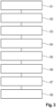
Figur 3 ein Flussdiagramm eines erfindungsgemäßen Verfahrens zur Verzögerung des erfindungsgemäßen einspurigen Kraftfahrzeugs gemäßFigur 1 . - In
Figur 1 ist ein erfindungsgemäßes einspuriges Kraftfahrzeug 10 mit einem Hinterrad 12 und einer Hinterradbremse 14 sowie einem Vorderrad 16 und einer Vorderradbremse 18, einem Motor 20 und einer Steuereinheit 22 dargestellt. - Die Steuereinheit 22 umfasst eine mit dem Motor 20 gekoppelte Motorsteuerung 24 und eine mit der Hinterradbremse 14 und der Vorderradbremse 18 gekoppelte Bremsensteuerung 26.
- Die Motorsteuerung 24 steuert demnach den Motor 20 und die Bremsensteuerung 26 steuert demnach die Hinterradbremse 14 und die Vorderradbremse 18.
- Die Hinterradbremse 14 und die Vorderradbremse 18 stellen zusammen eine Bremsanlage des Kraftfahrzeugs 10 dar, die ein Antiblockiersystem (ABS) umfassen kann. Die Bremsensteuerung 26 kann auch die Steuerung des ABS sein.
- Die Motorsteuerung 24 und die Bremsensteuerung 26 können ein Teil der Steuereinheit 22 sein oder jeweils eine eigene, separate Steuerung ausbilden.
- In der hier gezeigten Ausführungsform sind die Motorsteuerung 24 und die Bremsensteuerung 26 Teil der Steuereinheit 22 und stehen in Datenverbindung miteinander.
- Des Weiteren weist das Kraftfahrzeug 10 eine Vielzahl an Sensoriken auf, die mit der Steuereinheit 22 gekoppelt sind.
- Am Hinterrad 12 hat das Kraftfahrzeug 10 zum einen eine Hinterrad-Bremsdrucksensorik 28 und zum anderen eine Hinterrad-Raddrehzahlsensorik 30.
- Am Vorderrad 16 hat das Kraftfahrzeug 10 zum einen eine Vorderrad-Bremsdrucksensorik 32 und zum anderen eine Vorderrad-Raddrehzahlsensorik 34.
- Zudem weist das Kraftfahrzeug 10 eine Lenkwinkelsensorik 36 und eine inertiale Messsensorik 38 auf.
- Die inertiale Messsensorik 38 kann beispielsweise drei Beschleunigungssensoren und drei Drehratensensoren umfassen, durch die unter anderem eine Schräglage sowie ein Schwimmwinkel des Kraftfahrzeugs 10 erfasst werden können.
- Optional kann das Kraftfahrzeug 10 eine oder mehrere Benutzerschnittstelle(n) aufweisen, beispielsweise in Form eines Eingabegeräts 40 oder mehrerer Eingabegeräte 40, die mit der Steuereinheit 22 in Datenverbindung steht bzw. stehen.
- Mittels der
Figuren 2 und3 wird im Folgenden ein Verfahren zum Verzögern des einspurigen Kraftfahrzeugs 10 erläutert. Ziel des Verfahrens ist es, ein durch einen Fahrer des Kraftfahrzeugs 10 eingeleitetes Fahrmanöver zu unterstützen und dabei zu vereinfachen. - Anhand
Figur 2 wird das Grundprinzip des Verfahrens beschrieben. - Das gewünschte Fahrmanöver ist ein kontrolliertes, beabsichtigtes Überbremsen des Hinterrads 12, wodurch ein kontrollierter, stabiler "Slide" des Hinterrads 12 erzeugt werden soll, um dadurch eine stärkere Verzögerung des Kraftfahrzeugs zu erreichen als sie bei einem normalen Anbremsvorgang möglich wäre.
- Dazu erfasst die Bremsensteuerung 26 oder genauer die Bremsdrucksensorik 28, 32 der Steuereinheit 22 einen vom Fahrer durch Betätigung der Hinterradbremse 14 und/oder der Vorderradbremse 18 erzeugten Bremsdruck D, der zu einer Verzögerung des Kraftfahrzeugs 10 führt.
- Der Bremsdruck D an der Hinterradbremse 14 und der Bremsdruck D an der Vorderradbremse 18 können hierbei unterschiedlich sein.
- Dabei kann die Steuereinheit 22 aufgrund verschiedener Fahrzeugparameter automatisch erkennen, dass das gewünschte Fahrmanöver durchgeführt werden soll.
- Alternativ kann der Steuereinheit 12 zeitlich vor oder während dem gewünschten Fahrmanöver durch eine manuelle Eingabe an einer der Eingabegeräte 40 mitgeteilt werden, dass das gewünschte Fahrmanöver beim nächsten Verzögern des Kraftfahrzeugs 10 bzw. jetzt durchgeführt werden soll.
- Anschließend bestimmt die Steuereinheit 22 sowohl anhand des erfassten Bremsdrucks D an der Hinterradbremse 14 und/oder der Vorderradbremse 18 als auch weiterer Daten der Raddrehzahlsensorik 30, 34, der Lenkwinkelsensorik 36 und der in der inertialen Messsensorik 38 ein Gesamtmoment GM, das am Hinterrad 12 notwendig ist, um das gewünschte Überbremsen und demnach den Slide des Hinterrads 12 einzuleiten.
- Die Grundidee des Verfahren ist es, einen Teil des notwendigen Gesamtmoments GM durch die Motorsteuerung 24 und einen anderen Teil des notwendigen Gesamtmoments GM durch die Bremsensteuerung 26 zu erzeugen.
- Das durch die Motorsteuerung 24 erzeugte Motorteilmoment M und das durch die Bremsensteuerung 26 erzeugte Bremsenteilmoment B ergeben zusammen das notwendige Gesamtmoment GM am Hinterrad 12.
- Die einzelnen Schritte des Verfahrens werden im Folgenden anhand der
Figur 3 genauer beschrieben. - In einem Schritt S1 betätigt der Fahrer des Kraftfahrzeugs 10 die Hinterradbremse 14 und/oder die Vorderradbremse 18, um eine Verzögerung des Kraftfahrzeugs 10 zu erreichen. Durch Betätigen der Hinterradbremse 14 und/oder der Vorderradbremse 18 erzeugt der Fahrer den Bremsdruck D an der Hinterradbremse 14 bzw. an der Vorderradbremse 18.
- In einem Schritt S2 erkennt die Steuereinheit 12, dass der Fahrer das gewünschte Fahrmanöver ausführen will.
- Die Erkennung kann einerseits automatisch erfolgen oder andererseits manuell induziert werden.
- Die automatische Erkennung erfolgt anhand von verschiedenen Fahrzeugparametern, wie beispielsweise des aktuellen Bremsdrucks D an der Hinterradbremse 14 und/oder der Vorderradbremse 18, eines aktuellen inertialen Zustands des Kraftfahrzeugs 10, insbesondere der aktuellen Schräglage und des aktuellen Schwimmwinkels, der aktuellen Verzögerung und einer aktuellen Geschwindigkeit des Kraftfahrzeugs 10.
- Bei der manuellen Indizierung wird der Steuereinheit 12 zeitlich vor oder während dem gewünschten Fahrmanöver durch manuelles Betätigen eines Auslösers durch den Fahrer mitgeteilt, dass das gewünschte Fahrmanöver beim nächsten Verzögern des Kraftfahrzeugs 10 bzw. jetzt - wenn das Kraftfahrzeug 10 gerade verzögert wird - durchgeführt werden soll.
- Der Auslöser kann beispielsweise eine durch den Fahrer manuelle Eingabe an einer der Eingabegeräte 40 sein.
- Zusätzlich oder alternativ kann ein kurzes manuelles Betätigen der Hinterradbremse 14 durch den Fahrer als Auslöser dienen.
- In einem Schritt S3 wird durch die Steuereinheit 22 anhand aktueller Messdaten der Bremsdrucksensorik 28, 32, der Raddrehzahlsensorik 30, 34, der Lenkwinkelsensorik 36 und der inertialen Messsensorik 38 das Gesamtmoment GM bestimmt, das zum Einleiten des Slides des Hinterrads 12 notwendig ist.
- Auf Grundlage des bestimmten Gesamtmoments GM ermittelt die Bremsensteuerung 26 in einem Schritt S4 unter Einbezug der Verzögerung des Kraftfahrzeugs 10 einen Soll-Bremsdruck DSoll, mit dem die Hinterradbremse 14 betätigt werden soll, um das Bremsenteilmoment B am Hinterrad 12 zu erzeugen, das grob, d. h. in etwa, dem bestimmten Gesamtmoment GM entsprechen soll.
- Die Verzögerung wird einerseits mittels der inertialen Messsensorik 38 und andererseits aus dem aktuellen Bremsdruck B der Vorderradbremse 18 ermittelt.
- Durch Betätigen der Hinterradbremse 14 durch die Bremsensteuerung 26 oder das durch die Bremsensteuerung 26 gesteuerte ABS mit dem ermittelten Soll-Bremsdruck DSoll wird in einem Schritt S5 das Bremsenteilmoment B am Hinterrad 12 erzeugt.
- Es ist demnach möglich, dass die Steuereinheit 12 bzw. die Bremsensteuerung 26 vollautomatisch das Bremsenteilmoment B am Hinterrad 12 erzeugt, ohne dass der Fahrer des Kraftfahrzeugs 10 die Hinterradbremse 14 selbst betätigen muss.
- Im Falle einer Betätigung der Hinterradbremse 14 durch den Fahrer kann die Bremsensteuerung 26 eine Bremsdruckbegrenzung der Hinterradbremse 14 darstellen, durch die der vom Fahrer aufgebrachte Bremsdruck D auf den Soll-Bremsdruck DSoll eingestellt, insbesondere verringert wird. Diese Teilfunktion nimmt dem Fahrer die richtige Dosierung der Hinterradbremse 14 ab, da er diese nur noch stark betätigen muss, während die Bremsensteuerung 26 den tatsächlich notwendigen Soll-Bremsdruck DSoll einstellt.
- Auf Grundlage des bestimmten Gesamtmoments GM und optional auf Grundlage des durch die Bremsensteuerung 26 erzeugten aktuellen Bremsenteilmoments B am Hinterrad 12 ermittelt die Motorsteuerung 24 in einem Schritt S6 unter Einbezug eines aktuellen Schlupfs des Hinterrads 12, eines aktuellen inertialen Zustands des Kraftfahrzeugs 10, insbesondere der aktuellen Schräglage und des aktuellen Schwimmwinkels, der aktuellen Verzögerung und einer aktuellen Geschwindigkeit des Kraftfahrzeugs 10 einen Sollwert für den Schlupf des Hinterrads 12.
- Der Schlupf ergibt sich aus einer Abweichung einer Umfangsgeschwindigkeit des Hinterrads 12 von einer Umfangsgeschwindigkeit des Vorderrads 16. Der Schlupf wird somit aus den erfassten Daten der Raddrehzahlsensorik 30, 34 bestimmt.
- Die Schlupfregelung erfolgt über das Regeln eines Motordrehmoments, über das wiederrum das Motorteilmoment M am Hinterrad 12 erzeugt wird.
- Dazu wird in einem Schritt S7 ein Soll-Drehmoment des Motors 20 durch die Motorsteuerung 24 ermittelt, das die Raddrehzahl des Hinterrads 12 derart einstellt, dass der Soll-Schlupf am Hinterrad 12 erreicht wird, oder anders ausgedrückt, das das durch die Bremsensteuerung 26 erzeugte aktuelle Bremsenteilmoment B am Hinterrad 12 durch Erzeugen des zusätzlichen Motorteilmoment M auf das bestimmte Gesamtmoment GM einstellt.
- In einem Schritt S8 wird das aktuelle Drehmoment des Motors 20 auf das ermittelte Soll-Drehmoment geregelt, wodurch das Motorteilmoment M zusätzlich zum durch die Bremsensteuerung 26 erzeugten Bremsenteilmoment B am Hinterrad 12 erzeugt und somit der ermittelte Soll-Schlupf und folglich das bestimmte, notwendige Gesamtmoment GM erreicht wird.
- Das Regeln des Drehmoments des Motors 20 kann beispielsweise durch das Ansteuern des gesamten Motors 20, einzelner Zylinderbänke und/oder einzelner Zylinder in an sich bekannter Weise erfolgen.
- Demnach nimmt die Motorsteuerung 24 eine Art Feinjustierung des durch die Bremsensteuerung 26 "grob" erzeugten Bremsenteilmoments B am Hinterrad 12 vor, um das aktuelle Hinterraddrehmoment (=̂ Bremsenteilmoment B) auf das bestimmte Gesamtmoment GM einzustellen, insbesondere zu vergrößern.
- In Summe ergeben das Bremsenteilmoment B und das Motorteilmoment M somit das Gesamtmoment GM.
- Zusammenfassend wird durch die Bremsensteuerung 26 das aktuelle Drehmoment am Hinterrad 12 grob auf das notwendige Gesamtmoment GM eingestellt und durch die Motorsteuerung 24 das von der Bremsensteuerung 26 erzeugt aktuelle Drehmoment am Hinterrad 12 durch Regeln des Motordrehmoments auf das notwendige Gesamtmoment GM feinjustiert.
- Optional können über die Benutzerschnittstelle bzw. das Eingabegerät 40 verschiedene Einstellungen, beispielsweise Radeigenschaften wie der Reifentyp, und/oder Fahrmodi, beispielsweise Sportmodus mit besonders stark ausgeprägtem Slideverhalten, vorgenommen werden. Diese Einstellungen haben Einfluss auf das Verzögerungsverhalten des Kraftfahrzeugs 10 und somit auch auf die Ermittlung des Gesamtmoments GM oder der Teilmomente B, M.
Claims (10)
- Verfahren zum Verzögern eines einspurigen Kraftfahrzeugs (10), mit den folgenden Schritten:a) Bestimmen eines für ein kontrolliertes Überbremsen eines Hinterrads (12) beim Anbremsen einer Kurve benötigten Gesamtmoments (GM) des Hinterrads (12) des Kraftfahrzeugs (10) durch eine Steuereinheit (22) des Kraftfahrzeugs (10),b) Ermitteln eines Bremsenteilmoments (B) und eines Motorteilmoments (M) durch die Steuereinheit (22) in Abhängigkeit des benötigten Gesamtmoments (GM), undc) Erzeugen des Bremsenteilmoments (B) am Hinterrad (12) durch Ansteuern einer Bremsanlage des Kraftfahrzeugs (10) durch die Steuereinheit (22) und Erzeugen des Motorteilmoments (M) am Hinterrad (12) durch Ansteuern eines Motors (20) des Kraftfahrzeugs (10) durch die Steuereinheit (22).
- Verfahren nach Anspruch 1, dadurch gekennzeichnet, dass das Bremsenteilmoment (B) und das Motorteilmoment (M) in Summe das benötigte Gesamtmoment (GM) ergeben.
- Verfahren nach Anspruch 1 oder 2, dadurch gekennzeichnet, dass die Bremsanlage eine Bremsensteuerung (26) aufweist, die einen Teil der Steuereinheit (22) darstellt, insbesondere wobei die Bremsanlage ein Antiblockiersystem umfasst, und/oder dass das Kraftfahrzeug (10) eine Motorsteuerung (24) aufweist, die einen Teil der Steuereinheit (22) darstellt.
- Verfahren nach einem der vorhergehenden Ansprüche, dadurch gekennzeichnet, dass zum Erzeugen des Bremsenteilmoments (B) am Hinterrad (12) die folgenden weiteren Schritte durchgeführt werden:- Ermitteln eines Soll-Bremsdrucks (DSoll) der Bremsanlage in Abhängigkeit des ermittelten Bremsenteilmoments (B) durch die Steuereinheit (22), insbesondere die Bremsensteuerung (26), und- Erzeugen des Bremsenteilmoments (B) durch Betätigen der Bremse (14, 18) der Bremsanlage durch die Steuereinheit (22) mit dem ermittelten Soll-Bremsdruck (DSoll).
- Verfahren nach Anspruch 4, dadurch gekennzeichnet, dass ein vom Fahrer aufgebrachter Bremsdruck (D) durch Ansteuerung der Bremsanlage durch die Steuereinheit (22), insbesondere die Bremsensteuerung (26), auf den Soll-Bremsdruck (DSoll) reduziert wird.
- Verfahren nach einem der vorhergehenden Ansprüche, dadurch gekennzeichnet, dass zum Erzeugen des Motorteilmoments (M) die folgenden weiteren Schritte durchgeführt werden:- Ermitteln eines Soll-Drehmoments des Motors (20) auf Grundlage des ermittelten Motorteilmoments (M), und- Erzeugen des Motorteilmoments (M) durch Regeln des Motors (20) auf das Soll-Drehmoment durch die Steuereinheit (22), insbesondere die Motorsteuerung (24).
- Verfahren nach Anspruch 6, dadurch gekennzeichnet, dass das Regeln des Motors (20) auf das ermittelte Soll-Drehmoment durch Ansteuern des gesamten Motors (20), einzelner Zylinder und/oder einzelner Zylinderbänke des Motors (20) erfolgt.
- Verfahren nach einem der vorhergehenden Ansprüche, dadurch gekennzeichnet, dass das Gesamtmoment (GM), das Bremsenteilmoment (B), insbesondere der Soll-Bremsdruck (DSoll), und/oder das Motorteilmoment (M), insbesondere das Soll-Drehmoment, auf Grundlage eines aktuellen Lenkwinkels, einer aktuellen Raddrehzahl eines Vorderrads (16), einer aktuellen Raddrehzahl des Hinterrads (12), einer aktuellen Fahrzeuggeschwindigkeit, eines aktuellen Schlupfs des Vorderrads (16), eines aktuellen Schlupfs des Hinterrads (12), eines aktuellen inertialen Zustands, insbesondere einer aktuellen Schräglage und/oder eines aktuellen Schwimmwinkels des Kraftfahrzeugs (10), eines gewählten Fahrmodus und/oder eines vom Fahrer aufgebrachten Bremsdrucks (D), insbesondere am Vorderrad (16), ermittelt wird.
- Einspuriges Kraftfahrzeug (10) mit einem Vorderrad (16) und einem Hinterrad (12), einer Bremsanlage mit einer Vorderradbremse (18) und einer Hinterradbremse (14), einem Motor (20), zumindest einer Sensorik (28, 30, 32, 34, 36, 38) und einer mit der Bremsanlage, dem Motor (20) und der Sensorik (28, 30, 32, 34, 36, 38) gekoppelten Steuereinheit (22), die dazu ausgebildet ist, das Verfahren nach einem der vorhergehenden Ansprüche durchzuführen.
- Einspuriges Kraftfahrzeug (10) nach Anspruch 9, dadurch gekennzeichnet, dass die Sensorik eine Bremsdrucksensorik (28, 32), eine Lenkwinkelsensorik (36), eine inertiale Messsensorik (38), insbesondere zumindest einen Beschleunigungssensor und/oder zumindest einen Drehratensensor, und/oder eine Raddrehzahlsensorik (30, 34) umfasst.
Applications Claiming Priority (2)
| Application Number | Priority Date | Filing Date | Title |
|---|---|---|---|
| DE102020109232.6A DE102020109232A1 (de) | 2020-04-02 | 2020-04-02 | Verfahren sowie Kraftfahrzeug |
| PCT/EP2021/053008 WO2021197694A1 (de) | 2020-04-02 | 2021-02-09 | Verfahren sowie kraftfahrzeug |
Publications (2)
| Publication Number | Publication Date |
|---|---|
| EP4126616A1 EP4126616A1 (de) | 2023-02-08 |
| EP4126616B1 true EP4126616B1 (de) | 2024-12-11 |
Family
ID=74587030
Family Applications (1)
| Application Number | Title | Priority Date | Filing Date |
|---|---|---|---|
| EP21704491.6A Active EP4126616B1 (de) | 2020-04-02 | 2021-02-09 | Verfahren sowie kraftfahrzeug |
Country Status (5)
| Country | Link |
|---|---|
| US (1) | US12330615B2 (de) |
| EP (1) | EP4126616B1 (de) |
| CN (1) | CN114929536B (de) |
| DE (1) | DE102020109232A1 (de) |
| WO (1) | WO2021197694A1 (de) |
Families Citing this family (2)
| Publication number | Priority date | Publication date | Assignee | Title |
|---|---|---|---|---|
| DE102021211390A1 (de) * | 2021-10-08 | 2023-04-13 | Robert Bosch Gesellschaft mit beschränkter Haftung | Verfahren zum Betreiben eines Zweirads |
| EP4709624A1 (de) * | 2023-05-09 | 2026-03-18 | TVS Motor Company Limited | System zur stabilisierung eines fahrzeugs und verfahren dafür |
Family Cites Families (12)
| Publication number | Priority date | Publication date | Assignee | Title |
|---|---|---|---|---|
| DE102008011575B4 (de) * | 2007-03-16 | 2025-04-24 | Continental Automotive Technologies GmbH | Verfahren und Vorrichtung zur Stabilisierung eines einspurigen Kraftfahrzeugs |
| JP5272448B2 (ja) * | 2008-03-04 | 2013-08-28 | 日産自動車株式会社 | 車両用運転支援装置及び車両用運転支援方法 |
| DE102010003951A1 (de) * | 2010-04-14 | 2011-10-20 | Robert Bosch Gmbh | Verfahren zum Stabilisieren eines Zweirads bei seitlich rutschendem Hinterrad |
| DE102011076633A1 (de) * | 2010-09-14 | 2012-03-15 | Robert Bosch Gmbh | Schräglagenabhängige Anpassung einer Bremskraftregelung bei einspurigen Fahrzeugen |
| US9346510B2 (en) | 2011-07-28 | 2016-05-24 | Yamaha Hatsudoki Kabushiki Kaisha | Attitude controller and saddle riding type vehicle having the same |
| DE102012211963A1 (de) | 2012-07-10 | 2014-01-30 | Robert Bosch Gmbh | Verfahren zur Stabilisierung eines Zweirads bei Kurvenfahrt |
| DE102012222884A1 (de) * | 2012-12-12 | 2014-06-12 | Robert Bosch Gmbh | Verfahren zur Stabilisierung eines Zweirads |
| JP5873143B2 (ja) | 2014-07-08 | 2016-03-01 | ヤマハ発動機株式会社 | 鞍乗り型車両 |
| DE102014223463A1 (de) | 2014-11-18 | 2016-05-19 | Bayerische Motoren Werke Aktiengesellschaft | Zusatzbremsmodul für ein Motorrad |
| DE102014225625A1 (de) | 2014-12-11 | 2016-06-16 | Bayerische Motoren Werke Aktiengesellschaft | Verfahren zur Unterstützung eines Fahrers eines einspurigen Kraftfahrzeugs zum sicheren Befahren einer Kurve |
| DE102015214176A1 (de) | 2015-07-27 | 2017-02-02 | Continental Teves Ag & Co. Ohg | Verfahren zur Fahrerunterstützung bei Wasserglätte auf einem Fahrbahnuntergrund |
| DE102016200500A1 (de) | 2016-01-16 | 2017-07-20 | Robert Bosch Gmbh | Verfahren zur Stabilisierung eines Zweirads bei Kurvenfahrt |
-
2020
- 2020-04-02 DE DE102020109232.6A patent/DE102020109232A1/de active Pending
-
2021
- 2021-02-09 US US17/795,907 patent/US12330615B2/en active Active
- 2021-02-09 CN CN202180008941.8A patent/CN114929536B/zh active Active
- 2021-02-09 EP EP21704491.6A patent/EP4126616B1/de active Active
- 2021-02-09 WO PCT/EP2021/053008 patent/WO2021197694A1/de not_active Ceased
Also Published As
| Publication number | Publication date |
|---|---|
| WO2021197694A1 (de) | 2021-10-07 |
| DE102020109232A1 (de) | 2021-10-07 |
| CN114929536B (zh) | 2025-07-22 |
| EP4126616A1 (de) | 2023-02-08 |
| CN114929536A (zh) | 2022-08-19 |
| US20230086051A1 (en) | 2023-03-23 |
| US12330615B2 (en) | 2025-06-17 |
Similar Documents
| Publication | Publication Date | Title |
|---|---|---|
| EP1016572B1 (de) | Vorrichtung und Verfahren zur Stabilisierung eines aus einem Zugfahrzeug und einem Anhänger bzw. Auflieger bestehenden Fahrzeuggespannes | |
| DE4446592B4 (de) | Fahrdynamikregelsystem | |
| DE4446582B4 (de) | Fahrdynamikregelsystem | |
| EP1257432B1 (de) | Schaltungsanordung und vorrichtung zur regelung und steuerung der fahrgeschwindigkeit eines kraftfahrzeugs | |
| DE10054647A1 (de) | Verfahren zur Regelung der Fahrstabilität | |
| EP1556269B1 (de) | Verfahren zur bestimmung eines bei einer betätigung eines lenkrades wirkenden lenkmoments bei kraftfahrzeugen | |
| DE102011077153A1 (de) | Verfahren zum Modifizieren einer Fahrstabilitätsregelung eines Fahrzeugs und Elektronisches Steuergerät | |
| EP4126616B1 (de) | Verfahren sowie kraftfahrzeug | |
| DE102012200494B4 (de) | Verfahren zur Regelung einer Bremsanlage für Kraftfahrzeuge sowie Bremsanlage | |
| DE102007007442A1 (de) | Verfahren zur reibwertabhängigen Veränderung des Lenkmoments und Lenksystem zur Durchführung des Verfahrens | |
| EP1045783A1 (de) | Vorrichtung und verfahren zum begrenzen einer rückrollgeschwindigkeit eines kraftfahrzeuges | |
| DE60113223T2 (de) | Elektrische Servolenkung | |
| DE60034422T2 (de) | Erhöhung der Fahrzeugsteuerbarkeit und Fahrstabilität beim Bremsen in einer Kurve | |
| DE102019206883B4 (de) | Beenden einer Bankettfahrt eines Kraftfahrzeugs | |
| DE102004041413A1 (de) | Elektromechanische Lenkung mit dynamischer Lenkempfehlung | |
| DE10130659A1 (de) | Vorrichtung zur Stabilisierung eines Fahrzeuges | |
| EP2440439B1 (de) | Verfahren zur erzeugung eines auf die fahrzeugräder eines fahrzeugs wirkenden differenzmoments | |
| EP2247477B1 (de) | Verfahren und vorrichtung zum stabilisieren eines fahrzeugs | |
| DE10325486A1 (de) | Verfahren zur Regelung der Fahrstabilität | |
| EP0986498B1 (de) | Verfahren und vorrichtung zur regelung wenigstens einer fahrdynamikgrösse eines fahrzeuges | |
| DE10348399B4 (de) | Verfahren und Vorrichtung zum Verbessern der Steuerbarkeit eines Fahrzeugs in einer fahrdynamischen Grenzsituation | |
| DE102021206854A1 (de) | Verfahren zur Steuerung einer Annäherung eines Fahrzeugs, Abstandsregler, Computerprogramm und Speichereinheit | |
| DE10045611A1 (de) | Regeleinrichtung für Fahrzeuge | |
| DE102020209969A1 (de) | Zweiradfahrzeug mit verbessertem ABS sowie Verfahren hierzu | |
| EP2631130B1 (de) | Verfahren und Vorrichtung zur Bestimmung eines resultierenden Soll-Lenkwinkels sowie Verfahren zur Einstellung eines Soll-Lenkwinkels |
Legal Events
| Date | Code | Title | Description |
|---|---|---|---|
| STAA | Information on the status of an ep patent application or granted ep patent |
Free format text: STATUS: UNKNOWN |
|
| STAA | Information on the status of an ep patent application or granted ep patent |
Free format text: STATUS: THE INTERNATIONAL PUBLICATION HAS BEEN MADE |
|
| PUAI | Public reference made under article 153(3) epc to a published international application that has entered the european phase |
Free format text: ORIGINAL CODE: 0009012 |
|
| STAA | Information on the status of an ep patent application or granted ep patent |
Free format text: STATUS: REQUEST FOR EXAMINATION WAS MADE |
|
| 17P | Request for examination filed |
Effective date: 20221006 |
|
| AK | Designated contracting states |
Kind code of ref document: A1 Designated state(s): AL AT BE BG CH CY CZ DE DK EE ES FI FR GB GR HR HU IE IS IT LI LT LU LV MC MK MT NL NO PL PT RO RS SE SI SK SM TR |
|
| P01 | Opt-out of the competence of the unified patent court (upc) registered |
Effective date: 20230502 |
|
| DAV | Request for validation of the european patent (deleted) | ||
| DAX | Request for extension of the european patent (deleted) | ||
| P02 | Opt-out of the competence of the unified patent court (upc) changed |
Effective date: 20230808 |
|
| GRAP | Despatch of communication of intention to grant a patent |
Free format text: ORIGINAL CODE: EPIDOSNIGR1 |
|
| STAA | Information on the status of an ep patent application or granted ep patent |
Free format text: STATUS: GRANT OF PATENT IS INTENDED |
|
| INTG | Intention to grant announced |
Effective date: 20240904 |
|
| GRAS | Grant fee paid |
Free format text: ORIGINAL CODE: EPIDOSNIGR3 |
|
| GRAA | (expected) grant |
Free format text: ORIGINAL CODE: 0009210 |
|
| STAA | Information on the status of an ep patent application or granted ep patent |
Free format text: STATUS: THE PATENT HAS BEEN GRANTED |
|
| AK | Designated contracting states |
Kind code of ref document: B1 Designated state(s): AL AT BE BG CH CY CZ DE DK EE ES FI FR GB GR HR HU IE IS IT LI LT LU LV MC MK MT NL NO PL PT RO RS SE SI SK SM TR |
|
| REG | Reference to a national code |
Ref country code: GB Ref legal event code: FG4D Free format text: NOT ENGLISH |
|
| REG | Reference to a national code |
Ref country code: CH Ref legal event code: EP |
|
| REG | Reference to a national code |
Ref country code: DE Ref legal event code: R096 Ref document number: 502021006075 Country of ref document: DE |
|
| REG | Reference to a national code |
Ref country code: IE Ref legal event code: FG4D Free format text: LANGUAGE OF EP DOCUMENT: GERMAN |
|
| REG | Reference to a national code |
Ref country code: LT Ref legal event code: MG9D |
|
| PG25 | Lapsed in a contracting state [announced via postgrant information from national office to epo] |
Ref country code: HR Free format text: LAPSE BECAUSE OF FAILURE TO SUBMIT A TRANSLATION OF THE DESCRIPTION OR TO PAY THE FEE WITHIN THE PRESCRIBED TIME-LIMIT Effective date: 20241211 |
|
| PG25 | Lapsed in a contracting state [announced via postgrant information from national office to epo] |
Ref country code: FI Free format text: LAPSE BECAUSE OF FAILURE TO SUBMIT A TRANSLATION OF THE DESCRIPTION OR TO PAY THE FEE WITHIN THE PRESCRIBED TIME-LIMIT Effective date: 20241211 |
|
| PG25 | Lapsed in a contracting state [announced via postgrant information from national office to epo] |
Ref country code: BG Free format text: LAPSE BECAUSE OF FAILURE TO SUBMIT A TRANSLATION OF THE DESCRIPTION OR TO PAY THE FEE WITHIN THE PRESCRIBED TIME-LIMIT Effective date: 20241211 |
|
| REG | Reference to a national code |
Ref country code: NL Ref legal event code: MP Effective date: 20241211 |
|
| PG25 | Lapsed in a contracting state [announced via postgrant information from national office to epo] |
Ref country code: ES Free format text: LAPSE BECAUSE OF FAILURE TO SUBMIT A TRANSLATION OF THE DESCRIPTION OR TO PAY THE FEE WITHIN THE PRESCRIBED TIME-LIMIT Effective date: 20241211 |
|
| PG25 | Lapsed in a contracting state [announced via postgrant information from national office to epo] |
Ref country code: NO Free format text: LAPSE BECAUSE OF FAILURE TO SUBMIT A TRANSLATION OF THE DESCRIPTION OR TO PAY THE FEE WITHIN THE PRESCRIBED TIME-LIMIT Effective date: 20250311 |
|
| PG25 | Lapsed in a contracting state [announced via postgrant information from national office to epo] |
Ref country code: LV Free format text: LAPSE BECAUSE OF FAILURE TO SUBMIT A TRANSLATION OF THE DESCRIPTION OR TO PAY THE FEE WITHIN THE PRESCRIBED TIME-LIMIT Effective date: 20241211 Ref country code: GR Free format text: LAPSE BECAUSE OF FAILURE TO SUBMIT A TRANSLATION OF THE DESCRIPTION OR TO PAY THE FEE WITHIN THE PRESCRIBED TIME-LIMIT Effective date: 20250312 |
|
| PGFP | Annual fee paid to national office [announced via postgrant information from national office to epo] |
Ref country code: AT Payment date: 20250417 Year of fee payment: 5 |
|
| PG25 | Lapsed in a contracting state [announced via postgrant information from national office to epo] |
Ref country code: RS Free format text: LAPSE BECAUSE OF FAILURE TO SUBMIT A TRANSLATION OF THE DESCRIPTION OR TO PAY THE FEE WITHIN THE PRESCRIBED TIME-LIMIT Effective date: 20250311 |
|
| PG25 | Lapsed in a contracting state [announced via postgrant information from national office to epo] |
Ref country code: NL Free format text: LAPSE BECAUSE OF FAILURE TO SUBMIT A TRANSLATION OF THE DESCRIPTION OR TO PAY THE FEE WITHIN THE PRESCRIBED TIME-LIMIT Effective date: 20241211 |
|
| PG25 | Lapsed in a contracting state [announced via postgrant information from national office to epo] |
Ref country code: SM Free format text: LAPSE BECAUSE OF FAILURE TO SUBMIT A TRANSLATION OF THE DESCRIPTION OR TO PAY THE FEE WITHIN THE PRESCRIBED TIME-LIMIT Effective date: 20241211 |
|
| PG25 | Lapsed in a contracting state [announced via postgrant information from national office to epo] |
Ref country code: PL Free format text: LAPSE BECAUSE OF FAILURE TO SUBMIT A TRANSLATION OF THE DESCRIPTION OR TO PAY THE FEE WITHIN THE PRESCRIBED TIME-LIMIT Effective date: 20241211 |
|
| PG25 | Lapsed in a contracting state [announced via postgrant information from national office to epo] |
Ref country code: IS Free format text: LAPSE BECAUSE OF FAILURE TO SUBMIT A TRANSLATION OF THE DESCRIPTION OR TO PAY THE FEE WITHIN THE PRESCRIBED TIME-LIMIT Effective date: 20250411 |
|
| PG25 | Lapsed in a contracting state [announced via postgrant information from national office to epo] |
Ref country code: PT Free format text: LAPSE BECAUSE OF FAILURE TO SUBMIT A TRANSLATION OF THE DESCRIPTION OR TO PAY THE FEE WITHIN THE PRESCRIBED TIME-LIMIT Effective date: 20250411 |
|
| PG25 | Lapsed in a contracting state [announced via postgrant information from national office to epo] |
Ref country code: EE Free format text: LAPSE BECAUSE OF FAILURE TO SUBMIT A TRANSLATION OF THE DESCRIPTION OR TO PAY THE FEE WITHIN THE PRESCRIBED TIME-LIMIT Effective date: 20241211 |
|
| PG25 | Lapsed in a contracting state [announced via postgrant information from national office to epo] |
Ref country code: RO Free format text: LAPSE BECAUSE OF FAILURE TO SUBMIT A TRANSLATION OF THE DESCRIPTION OR TO PAY THE FEE WITHIN THE PRESCRIBED TIME-LIMIT Effective date: 20241211 |
|
| PG25 | Lapsed in a contracting state [announced via postgrant information from national office to epo] |
Ref country code: SK Free format text: LAPSE BECAUSE OF FAILURE TO SUBMIT A TRANSLATION OF THE DESCRIPTION OR TO PAY THE FEE WITHIN THE PRESCRIBED TIME-LIMIT Effective date: 20241211 |
|
| PG25 | Lapsed in a contracting state [announced via postgrant information from national office to epo] |
Ref country code: CZ Free format text: LAPSE BECAUSE OF FAILURE TO SUBMIT A TRANSLATION OF THE DESCRIPTION OR TO PAY THE FEE WITHIN THE PRESCRIBED TIME-LIMIT Effective date: 20241211 |
|
| PG25 | Lapsed in a contracting state [announced via postgrant information from national office to epo] |
Ref country code: SE Free format text: LAPSE BECAUSE OF FAILURE TO SUBMIT A TRANSLATION OF THE DESCRIPTION OR TO PAY THE FEE WITHIN THE PRESCRIBED TIME-LIMIT Effective date: 20241211 |
|
| REG | Reference to a national code |
Ref country code: DE Ref legal event code: R097 Ref document number: 502021006075 Country of ref document: DE |
|
| PG25 | Lapsed in a contracting state [announced via postgrant information from national office to epo] |
Ref country code: MC Free format text: LAPSE BECAUSE OF FAILURE TO SUBMIT A TRANSLATION OF THE DESCRIPTION OR TO PAY THE FEE WITHIN THE PRESCRIBED TIME-LIMIT Effective date: 20241211 |
|
| REG | Reference to a national code |
Ref country code: CH Ref legal event code: PL |
|
| PG25 | Lapsed in a contracting state [announced via postgrant information from national office to epo] |
Ref country code: DK Free format text: LAPSE BECAUSE OF FAILURE TO SUBMIT A TRANSLATION OF THE DESCRIPTION OR TO PAY THE FEE WITHIN THE PRESCRIBED TIME-LIMIT Effective date: 20241211 |
|
| PG25 | Lapsed in a contracting state [announced via postgrant information from national office to epo] |
Ref country code: LU Free format text: LAPSE BECAUSE OF NON-PAYMENT OF DUE FEES Effective date: 20250209 |
|
| PLBE | No opposition filed within time limit |
Free format text: ORIGINAL CODE: 0009261 |
|
| STAA | Information on the status of an ep patent application or granted ep patent |
Free format text: STATUS: NO OPPOSITION FILED WITHIN TIME LIMIT |
|
| PG25 | Lapsed in a contracting state [announced via postgrant information from national office to epo] |
Ref country code: CH Free format text: LAPSE BECAUSE OF NON-PAYMENT OF DUE FEES Effective date: 20250228 |
|
| 26N | No opposition filed |
Effective date: 20250912 |
|
| REG | Reference to a national code |
Ref country code: BE Ref legal event code: MM Effective date: 20250228 |
|
| PG25 | Lapsed in a contracting state [announced via postgrant information from national office to epo] |
Ref country code: BE Free format text: LAPSE BECAUSE OF NON-PAYMENT OF DUE FEES Effective date: 20250228 |
|
| PG25 | Lapsed in a contracting state [announced via postgrant information from national office to epo] |
Ref country code: IE Free format text: LAPSE BECAUSE OF NON-PAYMENT OF DUE FEES Effective date: 20250209 |
|
| PGFP | Annual fee paid to national office [announced via postgrant information from national office to epo] |
Ref country code: GB Payment date: 20260219 Year of fee payment: 6 |
|
| PGFP | Annual fee paid to national office [announced via postgrant information from national office to epo] |
Ref country code: DE Payment date: 20260210 Year of fee payment: 6 |
|
| PGFP | Annual fee paid to national office [announced via postgrant information from national office to epo] |
Ref country code: IT Payment date: 20260227 Year of fee payment: 6 |
|
| PGFP | Annual fee paid to national office [announced via postgrant information from national office to epo] |
Ref country code: FR Payment date: 20260223 Year of fee payment: 6 |