EP4126503B1 - Verfahren zur herstellung einer hülle zum abdecken eines behälters und vorrichtung zur herstellung der hülle - Google Patents
Verfahren zur herstellung einer hülle zum abdecken eines behälters und vorrichtung zur herstellung der hülle Download PDFInfo
- Publication number
- EP4126503B1 EP4126503B1 EP21714267.8A EP21714267A EP4126503B1 EP 4126503 B1 EP4126503 B1 EP 4126503B1 EP 21714267 A EP21714267 A EP 21714267A EP 4126503 B1 EP4126503 B1 EP 4126503B1
- Authority
- EP
- European Patent Office
- Prior art keywords
- shrink label
- strip
- sleeve
- bottle
- puncture
- Prior art date
- Legal status (The legal status is an assumption and is not a legal conclusion. Google has not performed a legal analysis and makes no representation as to the accuracy of the status listed.)
- Active
Links
Images


Classifications
-
- B—PERFORMING OPERATIONS; TRANSPORTING
- B29—WORKING OF PLASTICS; WORKING OF SUBSTANCES IN A PLASTIC STATE IN GENERAL
- B29C—SHAPING OR JOINING OF PLASTICS; SHAPING OF MATERIAL IN A PLASTIC STATE, NOT OTHERWISE PROVIDED FOR; AFTER-TREATMENT OF THE SHAPED PRODUCTS, e.g. REPAIRING
- B29C63/00—Lining or sheathing, i.e. applying preformed layers or sheathings of plastics; Apparatus therefor
- B29C63/38—Lining or sheathing, i.e. applying preformed layers or sheathings of plastics; Apparatus therefor by liberation of internal stresses
- B29C63/42—Lining or sheathing, i.e. applying preformed layers or sheathings of plastics; Apparatus therefor by liberation of internal stresses using tubular layers or sheathings
-
- B—PERFORMING OPERATIONS; TRANSPORTING
- B26—HAND CUTTING TOOLS; CUTTING; SEVERING
- B26F—PERFORATING; PUNCHING; CUTTING-OUT; STAMPING-OUT; SEVERING BY MEANS OTHER THAN CUTTING
- B26F1/00—Perforating; Punching; Cutting-out; Stamping-out; Apparatus therefor
- B26F1/0015—Perforating; Punching; Cutting-out; Stamping-out; Apparatus therefor specially adapted for perforating tubes
-
- B—PERFORMING OPERATIONS; TRANSPORTING
- B29—WORKING OF PLASTICS; WORKING OF SUBSTANCES IN A PLASTIC STATE IN GENERAL
- B29C—SHAPING OR JOINING OF PLASTICS; SHAPING OF MATERIAL IN A PLASTIC STATE, NOT OTHERWISE PROVIDED FOR; AFTER-TREATMENT OF THE SHAPED PRODUCTS, e.g. REPAIRING
- B29C2793/00—Shaping techniques involving a cutting or machining operation
- B29C2793/0045—Perforating
Definitions
- the present invention relates to a method of making a sleeve for covering a receptacle and an apparatus for making the sleeve.
- Containers such as bottles can have shrink labels attached thereon in order to display product names or the like and achieve decorative effects.
- a typical bottle may have a body that is configured to hold a product, such as a liquid, within an interior space of the body. The bottle may then have an opening to dispense product through the opening and a cap threadably coupled with the body to selectively close the opening of the bottle.
- the cap comprises a trigger and a nozzle to allow a user to squeeze the trigger to dispense the product within the bottle through the nozzle of the cap.
- the cap may comprise a plunger-type pump dispenser having a nozzle.
- a shrink label is typically applied to the bottle such that a top end of the shrink label is positioned just below the bottom of the cap such that the cap of the bottle is exposed.
- US2013/0061559A1 discloses a device for arranging a sleeve-like foil envelope around an object.
- the foil material is made of a so-called shrink material which shrinks as a result of heat being applied and which forms with a close fit to the shape of the bottle or container around which the sleeve-like envelope has been arranged.
- US 2009/056277 A1 discloses a method of making a sleeve for covering a receptacle in the form of a flower pot. Further, US 2009/056277 A1 discloses a sleeve having punctures being spaced apart from a first end and from a second end of the sleeve.
- the inventors have found that during shipping of the bottle, the cap may become loose relative to the bottle causing the product from the bottle to leak through the opening. It may therefore be desirable to provide a shrink label that further secures a cap relative to a bottle to prevent the cap from becoming loose relative to the bottle. This may thereby prevent a product from leaking from the bottle during shipping.
- a shrink label that further secures a cap relative to a bottle to prevent the cap from becoming loose relative to the bottle. This may thereby hinder a product from leaking from the bottle during shipping.
- a shrink label could be provided that extends upward from the bottle and onto a portion of the cap.
- the shrink label can thereby be (e . g . heat) shrunk onto the bottle and the cap to further secure the cap relative to the bottle and prevent the cap from loosening relative to the bottle during shipping. But this arrangement still leaves room for improvement with regards to hindering leakage.
- Corresponding objects apply generally to sleeves for covering a receptacle, a shrink label being a type of sleeve.
- a method of making a sleeve for covering a receptacle, from a strip of flexible tubular material, wherein the sleeve has a given length measured from a first end to a second end, being measured in the longitudinal direction of the strip comprises: puncturing the sleeve to form a puncture being spaced apart from the first end and from the second end, wherein said puncturing the sleeve is puncturing an open region of the sleeve.
- the protrusion of a receptacle can be inserted through the puncture.
- the puncture is made in the sleeve, which is tubular, i.e. after the material is formed as a tube. This allows higher production efficiency compared to, for example puncturing a non-tubular strip for each sleeve, the tube being subsequently bonded at its ends to form a tube.
- the sleeve is more robust.
- the shape of the puncture may be chosen to suit the shape of the protrusion.
- the puncture may have one or both of longitudinal and transverse extent.
- each sleeve end portion comprising a sleeve end is not punctured by making the puncture (there is a puncture-free region on either longitudinal end/ extent of the puncture); so the sleeve can better hinder loosening of any cap; when the receptacle has a nozzle, the sleeve can better hinder leakage from the nozzle. Even if the sleeve does not cover the nozzle, the nozzle as a protrusion can protrude through the slit so the sleeve is not excessively deformed or ruptured. The sleeve can hinder loosening (e.g. rotation and/or extension) of the cap and optionally any nozzle provided on it. So by puncturing an open region, the sleeve can be more easily and accurately punctured in the wall thickness direction
- the sleeve may be made by removing a length of tubular material from the strip. So the strip may have greater length than the given length of the sleeve, i.e. the strip of flexible tubular material may be long enough for several sleeves to be made (e.g. removed) from it. Puncturing the sleeve may therefore be understood to mean puncturing a length of tubular material separated from the strip; alternatively or in addition said length may be understood as an as-yet-unpunctured sleeve. Alternatively the strip may have the same length as the sleeve.
- Said puncturing may be done at a first distance from the free end.
- the sleeve may be cut from the (e.g. punctured) strip having greater length than the given length of the sleeve, such as a greater length before cutting the strip. So the production of multiple sleeves is facilitated.
- an apparatus for making a sleeve for covering a receptacle, from a strip of flexible tubular material, in particular for making the sleeve according to a method according to the invention, wherein the sleeve has a given length measured from a first end to a second end, being measured in the longitudinal direction of the strip, comprises a puncturing means configured to puncture an open region of the sleeve to form a puncture being spaced apart from the ends of the sleeve.
- the apparatus may comprise a cutting means configured to cut the sleeve from the strip, the strip having greater length that the given length of the sleeve.
- the apparatus may be configured to perform the method.
- Figs. 1 and 2 show views of a receptacle assembly having a first shrink label made according to a first embodiment and first to third examples not being part of the invention.
- a shrink label 20 is shown attached to a bottle 10.
- bottle 10 includes a body 12 defining an interior space for storing product.
- a top end portion of body 12 includes a neck 14 having an opening (not shown) to provide access to the product within body 12.
- Neck 14 is threadably coupled with cap 16.
- cap 16 may be coupled with bottle 10 using other suitable configurations, such as a snap fit, a friction fit, a living hinge, etc.
- Cap 16 includes a trigger 18 and a nozzle 19 such that a user may squeeze trigger 18 to pivot trigger 18 inwardly towards bottle 10 to thereby dispense the product within body 12 through nozzle 19.
- Shrink label 20 is shown positioned about bottle 10.
- Shrink label 20 may comprise any suitable plastic material that is configured to shrink and thereby form to bottle 10 when heated.
- Shrink label 10 comprises a lower portion 22 and an upper portion 24 separated by a first perforation line 26.
- Lower portion 22 of shrink label 20 thereby extends below first perforation line 26 to cover at least a portion of body 12 of bottle 10.
- Lower portion 22 may have a length of about 182 mm and a width of about 184 mm, but any other suitable dimensions may be used.
- lower portion 22 extends to a bottom end portion of bottle 10. In some other versions, lower portion 22 only extends to cover a portion of body 12.
- Upper portion 24 of shrink label 20 extends above first perforation line 26 to cover at least a portion of cap 16 of bottle 10.
- Upper portion 24 may have a length of about 101 mm and a width of about 184 mm, but any other suitable dimensions may be used.
- upper portion 24 extends to a top end portion of cap 16 such that upper portion 24 is configured to enclose nozzle 19. In some other versions, upper portion 24 only extends to cover a portion of cap 16.
- First perforation line 26 is positioned to extend circumferentially about shrink label 20 near neck 14 of bottle 10. In the illustrated embodiment, first perforation line 26 is positioned just below neck 14, but in other versions first perforation line 26 may be positioned at or above neck 14. First perforation line 26 also extends continuously about the entire circumference of shrink label 20. In some other versions, first perforation line 26 extends about only a portion of shrink label 20. Shrink label 10 further comprises one or more second perforation lines 28 extending transversely relative to first perforation line 26, through upper portion 24 of shrink label 20, from first perforation line 26 to a top portion of bottle 10. As shown in Fig.
- second perforation line 28 may be oriented obliquely relative to first perforation line 26 in an open configuration such that second perforation line 28 is oriented substantially vertical after shrink label 20 has been applied to bottle 10, as shown in Figs. 1 and 2 .
- First and second perforation lines 26, 28 thereby allow a user to remove upper portion 24 of shrink label 20 prior to use of bottle 10.
- shrink label 20 further comprises an opening 29 extending through upper portion 24 to allow trigger 18 of bottle 10 to be exposed through opening 29.
- shrink label 20 has a third perforation line 27 extending along upper portion 24 transverse to first perforation line 26.
- third perforation line 27 extends along only a portion of upper portion 24 such that third perforation line 27 is positioned above first perforation line 26 and below a top end surface of upper portion 24.
- Third perforation line 27 may have a length of about 55 mm, and be positioned about 16 mm above first perforation line 26 and about 30 mm below the top end surface of shrink label 20, but any other suitable dimensions can be used.
- third perforation line 27 thereby generally corresponds to the length of trigger 18, but any other suitable lengths can be used.
- Third perforation line 27 is formed such that third perforation line 27 is configured to rip more easily than First and second perforation lines 26, 28. Accordingly, when shrink label 20 is heated and shrunk about bottle 10 to form to bottle 10, third perforation line 27 breaks along third perforation line 27 to form opening 29. Trigger 18 of bottle 10 can thereby extend through opening 29.
- third perforation line 27 may be formed as a slit instead of perforations such that the slit is configured to expand as shrink label 20 is applied to bottle 10. Still other suitable configurations for third perforation line 27 will be apparent to one with ordinary skill in the art in view of the teachings herein.
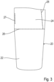
- Fig. 3 shows the shrink label 20 of the receptacle assembly described above in an expanded (i.e. not shrunk) configuration.
- a use of the shrink label 20 to cover a bottle, thus forming the receptacle assembly of Fig. 1 is described in the following.
- bottle 10 may be positioned within shrink label 20 in an open configuration, as shown in Fig. 3 .
- body 12 of bottle 10 may be aligned with lower portion 22 of shrink label 20
- neck 14 of bottle 10 may be aligned near first perforation line 26 of shrink label 20
- cap 16 of bottle may be aligned with upper portion 24 of shrink label 20 to position trigger 18 adjacent with third perforation line 27.
- Energy such as heat may then be applied to shrink label 20 such that shrink label 20 shrinks to form to bottle 10, as shown in Figs. 1 and 2 .
- third perforation line 27 breaks apart to form opening 29 to allow trigger 18 to extend through opening 29 while enclosing nozzle 19.
- Shrink label 20 thereby holds the position of the cap 16 relative to the bottle 10 to further secure the cap 16 with the bottle 10. This prevents the cap 16 from rotating and/or loosening relative to the bottle 10 to prevent product from leaking from the bottle 10. Opening 29 of shrink label 20 may also inhibit shrink label 20 from incidentally leaking product during the heat shrink process. For instance, as shrink label 20 is applied to bottle 10, compressive forces from shrink label 20 may pivot trigger 18 to incidentally leak product from bottle 10. Opening 29 thereby allows trigger 18 to extend through opening 29 to inhibit shrink label 20 from pivoting trigger 18 and incidentally leaking product.
- shrink label 20 may comprise a pull-tab to aid in removing a portion of the shrink label 20.
- a second shrink label made according to a first example not being part of the invention is shown in Fig. 4 and differs from the first shrink label 20 in the following.
- the second shrink label 20A has a single slit 27A instead of the third perforation line 27. In this case it is not necessary to break apart any perforation line to form the opening 29.
- the shrink label shrinks (e.g. upon applying energy such as heat) and /or when the trigger penetrates the slit, the slit widens to form the opening 29 having smooth sides.
- the slit 27A and above-mentioned third perforation line 27 are each examples of a puncture.
- the puncture may extend along any or both of: at least parts of the upper portion 24, and at least parts of the lower portion 22.
- the puncture may extend at least partially longitudinally.
- the first 26A and second 28A perforation lines correspond to the perforation lines 26 and 28 of the first shrink label 20.
- the shrink label 20A can be used in place of the shrink label 20 for covering the bottle 10.
- Fig. 5 shows a view of another receptacle assembly, which has a third shrink label made according to a first embodiment and first to third examples not being part of the invention.
- Fig. 6 shows the shrink label 20B for the receptacle assembly of Fig. 5 in an expanded (i.e. not shrunk) configuration.
- a shrink label 20B is shown attached to a bottle 100 including a body 120 defining an interior space for storing product.
- a cap 160 is fixed to an opening in a neck 140 of the bottle at the top of the bottle, such as by screwing, snap fit, a friction fit, a living hinge, etc.
- Cap 160 includes a pump mechanism which has a plunger 180 and a nozzle 19. A user can push down on the plunger 180 to dispense product within body 120 through nozzle 190.
- Shrink label 20B is shown positioned about bottle 100.
- the shrink label 20B may be made from the same materials as the first 20 and second 20A shrink labels.
- Shrink label 10 comprises a lower portion 22B and an upper portion 24B separated by a first perforation line 26B.
- Lower portion 22B of shrink label 20B thereby extends below first perforation line 26B to cover at least a portion of body 120 of bottle 100.
- Lower portion 22B extends to a bottom end portion of bottle 100. In some other versions, lower portion 22B only extends to cover a portion of body 120.
- Upper portion 24B of shrink label 200 extends above first perforation line 26B to cover at least a portion of cap 160 of bottle 100.
- Upper portion 24B extends to a top end portion of cap 160.
- First perforation line 26B is positioned to extend circumferentially about shrink label 20B near neck 140 of bottle 100.
- First perforation line 26B is positioned just below neck 140, but in other versions first perforation line 26B may be positioned at or above neck 140.
- First perforation line 26B also extends continuously about the entire circumference of shrink label 20B. In some other versions, first perforation line 26B extends about only a portion of shrink label 20B.
- Shrink label 100 further comprises one or more second perforation lines 28B extending transversely relative to first perforation line 26B, through upper portion 24B of shrink label 20B, from first perforation line 26B to a top portion of bottle 100.
- First and second perforation lines 26B, 28B correspond to the first 26, 26A and second perforation lines 28, 28A of the first 20 and second 20A shrink labels. They equally allow a user to remove upper portion 24B of shrink label 20B prior to use of bottle 100.
- shrink label 20B further comprises an opening 29B extending through upper portion 24B to allow nozzle 190 of bottle 100 to be exposed through opening 29B.
- shrink label 20B has a puncture 27B extending along upper portion 24B parallel to first perforation line 26B.
- the puncture comprises a central portion 271B formed as a (non-perforated) slit, and a respective perforated portion 272B, 273B on either side of the central portion 271B.
- the central portion 271B may directly join and/ or be aligned with the perforated portions 272B, 273B.
- Puncture 27B extends along only a portion of upper portion 24B and puncture 27B is positioned above first perforation line 26B and below a top end surface of upper portion 24B.
- the width of puncture 27B thereby generally corresponds to the width of the nozzle 190, but any other suitable lengths can be used.
- Puncture 27B is configured to rip more easily than first and second perforation lines 26B, 28B. Accordingly, when shrink label 20B is heated and shrunk about bottle 100 to form to bottle 100, puncture 27B breaks at its perforated portions 272B, 272C to form opening 29B. Nozzle 190 can thereby extend through opening 29B. Additionally or alternatively, puncture 27B may be formed entirely as a slit. Still other suitable configurations for puncture 27B will be apparent to one with ordinary skill in the art in view of the teachings herein. In typical examples the puncture 27B is positioned closer to one end of the shrink label than the punctures 27 and 27A are.
- bottle 100 may be positioned within shrink label 20B in an open configuration, as shown in Fig. 6 .
- body 120 of bottle 100 may be aligned with lower portion 22B of shrink label 20B
- neck 140 of bottle 100 may be aligned near first perforation line 26B of shrink label 20B
- cap 160 of bottle may be aligned with upper portion 24B of shrink label 20B to position nozzle 190 adjacent with puncture 27B.
- Energy such as heat may then be applied to shrink label 20B such that shrink label 20B shrinks to form to bottle 100, as shown in Figs. 5 and 6 .
- shrink label 20B forms to bottle 100
- the perforated end portions 272B, 273B of the puncture 27B break apart to form opening 29B wider than the central portion 271B, to allow nozzle 190 to extend through opening 29B.
- Shrink label 20B thereby holds the position of the cap 160 relative to the bottle 100 to further secure the cap 160 with the bottle 100, especially because the shrink label 20B has unpunctured regions above and below the nozzle 190. This more securely hinders the cap 160 from rotating and/or loosening relative to the bottle 100 to hinder product from leaking from the bottle 100.
- the shrink label 20B may function also as a tamper-evident seal.
- shrink label 20B may comprise a pull-tab to aid in removing a portion of the shrink label 20B.
- a shrink label for application to a bottle comprises a lower portion and an upper portion, wherein the lower portion is configured to be applied to at least a portion of a body of the bottle, wherein the upper portion is configured to be applied to at least a portion of a cap of the bottle, wherein the upper portion comprises a puncture such as a perforation line extending along a portion of the upper portion, wherein the puncture is configured to expand when the shrink label is applied to the bottle to form an opening, wherein a protrusion of the cap such as a trigger or a nozzle is positioned to extend through the opening.
- a method of applying a shrink label to a bottle comprising the steps of: positioning the shrink label about the body such that the lower portion of the shrink label is aligned with at least a portion of the body and the upper portion of the shrink label is aligned with at least a portion of the cap, wherein the puncture is positioned adjacent to the protrusion; applying heat to the shrink label to form the shrink label to the bottle; expanding the puncture to form an opening in the shrink label; and positioning the protrusion through the opening.
- the trigger is positioned through the opening, reducing leakage through an undesired trigger actuation; the nozzle is covered by the shrink label, further reducing leakage; the shrink label covers (is shrunk around) at least part of the cap and at least part of the body with a close fit, reducing undesired loosening of the cap; this hinders leakage; the shrink label has a larger surface area (advantageously a large design area can be implemented).
- the compound slit 27B may be replaced with a puncture comprising only a transverse slit or only a transverse perforation.
- the apparatus 30 comprises a mandrel 32 configured to receive a continuous strip 36 of flexible tubular material.
- the mandrel 32 is essentially columnar and has a vertical and stationary longitudinal axis.
- a top portion (not shown) of the mandrel 32 has a spreading element known in the art which can convert a strip of flexible tubular material from a flat form to an open form.
- the lower portion of the mandrel is shown in Fig. 7 and has a circular section. In variants of the present example the mandrel may have any one or more of a circular, oval, polygonal and plate-like section.
- the strip 36 can be introduced to the mandrel 32 from a roll (not shown) which is prepared in advance.
- the lower portion of the mandrel may be formed from a sleeve shot part of the mandrel.
- the apparatus 30 comprises advancing means which are known in the art and not shown, for feeding the strip 36.
- the advancing means may comprise one or more first pairs of rollers which engage with the inner and outer faces of the wall of the strip 36. In this way the strip 36 can be fed onto the mandrel 32 from the mandrel's upper end.
- the advancing means may comprise one or more second pairs of rollers which engage with the inner and outer faces of the wall of the strip 36 at a lower position on the mandrel 32 than the first pairs of rollers. In this way a sleeve cut from the strip 36 can be fed from the lower end of the mandrel to another production station.
- One or more of the rollers may be driven by an electric motor.
- One roller in each pair of rollers may be accommodated in recesses (not shown) provided in the mandrel 32.
- the mandrel 32 may be supported by some of the rollers.
- the apparatus 30 comprises a slitting blade 40, as a puncturing means, driven by a puncturing mechanism (not shown). More specifically, the mechanism moves the blade 40 toward and away from the mandrel in the radial directions shown by the double-headed arrow 42. In the present example the movement is linear but in other examples the movement may comprise any or more of a linear, circular, and elliptical motion.
- the blade 40 may rotate about an axis: specifically the blade 40 may be a rotating (spinning) blade whose cutting profile is eccentric to its axis of rotation. The movement allows the blade 40 to penetrate the strip 36 to make a slit in a region of the strip 36.
- the motion of the blade 40 may be driven any one or more of: electrically, pneumatically, and hydraulically.
- the blade 40 may be driven by an electric motor such as a servomotor.
- the blade 40 is driven by a reciprocating pneumatic actuator.
- the blade 40 punctures the wall-thickness of the shrink label 20A from one (outer) side while the mandrel 32 (opening device) supports the strip 36 from the other (inner) side.
- the slit is preferably straight and/or longitudinal.
- the slit may have a length (longitudinal extent) greater than or equal to any of: 2 mm, 5 mm, 10 mm, 15 mm, 20 mm, 25 mm, and 55 mm.
- the blade 40 in the present example has a triangular shaped profile.
- the blade profile may alternatively comprise a plurality of triangular shapes arranged in a vertical line.
- the leading vertex of the triangular shape may have an angle of 45 degrees.
- the blade 40 is configured to create a continuous slit of predetermined length in the strip 36. By providing more than one triangular shape, such as a saw-tooth like profile, the required stroke of the blade 40 for a given slit length can be kept short.
- the mandrel 32 comprises a recess 44 on its surface for receiving the blade 40.
- the blade 40 can enter the recess 44 which is shaped in correspondence with the triangular profile of the blade 40.
- the recess may have other shapes, such as a straight or circular shape, and may extend in a peripheral direction at least partly around the mandrel 32.
- the recess 44 may be a through-hole.
- the recess may be configured so that the puncturing means 40 does not contact the mandrel 32.
- the apparatus 30 comprises a rotary cutter 46, as a cutting means, comprising one or more blades that can move toward and away from the mandrel in the radial directions shown by the double-headed arrow 43 so as to cut the strip 36 peripherally, above the blade 40.
- a rotary cutter known in the art can be used here.
- the rotary cutter 46 may be configured to make a peripheral cut at least partly during the puncturing of the strip 36.
- the assembly 30 has a perforation means 50, comprising perforating blades, for making the first and second perforation lines.
- the perforation means 50 may comprise a respective perforating blade or blades for each perforation line and /or it may comprise a common perforating blade.
- the perforation means 50 is configured to reciprocatingly puncture a portion or portions of the strip 36 upstream of the mandrel 32, the directions of reciprocation being shown by the double-headed arrow 52.
- the perforation means 50 is thus configured to puncture a flattened portion of the strip 36, for example by applying a perforation means commonly known in the art.
- the perforation means 50 may be provided downstream of the mandrel.
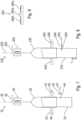
- FIGs. 10A to 10E represent procedures of the method which are performed using the apparatus 30 described above and shown in Fig. 7 .
- Step A As shown in Fig. 10A a strip 36 of tubular material is fed onto the mandrel 32 from the top portion of the mandrel 32, for example by means of the first roller pairs of the advancing means (not shown).
- the position in Fig. 10A may be at least partially achieved by cutting and removing a previously made shrink label from the strip 36.
- Step B The strip 36 is fed (such as by continuing the feeding in Step A) until the free end 33 of a free-end portion 34 of the strip 36 reaches a predetermined position along the mandrel 32, such as the bottom end of the mandrel 32 ( Fig. 10B ). Thus a region of the strip becomes an open region held open and/or supported by the mandrel 32. At this point the feeding is stopped.
- Step C Subsequently a puncturing step is performed ( Fig. 10C ), wherein the slitting blade 40 penetrates the strip 36 and enters the recess 44.
- the extents of the puncture 27A may be formed in correspondence with the extents of the blade 40.
- a longitudinally upper extent of the puncture 27A may be formed by (or in correspondence with) the longitudinally upper extent of the blade 40
- a longitudinally lower extent of the puncture may be formed by (or in correspondence with) the longitudinally lower extent of the blade 40. So the strip 36 is punctured at a first distance from its free end 33. Longitudinal end portions of the sleeve are not punctured in making the puncture. The first distance may be measured as the maximum longitudinal extent of the puncture from the free end.
- the strip 36 is cut about its periphery, optionally during the puncturing ( Fig. 10C ).
- the rotary cutter 46 may be configured to start and optionally complete the cutting before the puncturing.
- the blade 40 punctures a shrink label 20A that is already cut from the strip 36. So the strip 36 is cut at a second distance from its free end 33, the second distance being greater than the first distance.
- Step D After cutting, the rotary cutter 46 is retracted. After puncturing, the blade 40 is retracted (see Fig. 10D ). The end portion of the strip 36 forms the end portion of the shrink label 20A. The free end 33 becomes an open end of the shrink label 20A.
- the sleeve is made from the strip of tubular material by: feeding a free-end portion of a given length of the strip onto a columnar mandrel; puncturing the free-end portion at a first distance from its free end, transversely to the feeding direction, to form a puncture; and cutting the free-end portion from the strip at a second distance from its free end, the second distance being greater than the first distance.
- Step E Subsequently the shrink label 20A is advanced ( Fig. 10E ) in the direction of the solid arrow of Fig. 10E by means of the second pairs of rollers so that it leaves the mandrel 32 from the mandrel's bottom end.
- the not-shown advancing means may transfer the newly-made free-end portion 48 of the strip 36 to the predetermined position at the same time that, or shortly after, the shrink label 20A is transferred from the mandrel 32.
- the shrink label 20A is transferred from the mandrel 32 to a receptacle (not shown in Fig. 10A to 10E ), which is further preferably positioned under the mandrel 32.
- the method comprises a step (not shown in Figs. 10A to 10E ) of perforating a flattened portion of the strip 36, upstream to the mandrel, to form the first 26 and the second 28 perforation lines, by means of the perforation means 50.
- the first 26 and the second 28 perforation lines are provided on each shrink label 20A.
- the puncturing is performed on a portion of the strip 36, and the portion is provided on the mandrel 32, accuracy and repeatability are improved. Also the blade 40 is prevented from puncturing the wall of the strip 36 twice, as would be the case if the strip 36 were punctured in a flattened state. Puncturing is performed by moving the blade 40 in a plane parallel to the mandrel axis. So accuracy and repeatability of the puncturing can be further improved. Further preferably the slit (substantially) coincides in the peripheral direction with a longitudinal crease in the tubular material. The crease may be formed when the tubular material is flat. So insertion of a protrusion on a receptacle is facilitated.
- first and second perforation lines By forming the first and second perforation lines on a flattened part of the strip 36 it becomes easy to form pairs of parallel perforations, or to form a peripheral perforation.
- the processing time can be short.
- the not-shown advancing means, the blade 40, and the rotary cutter 46 may be configured to cooperate with timed fashion by means of a not-shown control unit.
- the free end 33; longitudinally lower extent of the puncture 27A; longitudinally upper extent of the puncture 27A; and location of cutting are longitudinally spaced from each other in that order.
- the puncture 27A is surrounded on all its sides by unpunctured material.
- the mandrel 32 may be stationary (e.g. rotationally stationary) during the puncturing and /or cutting.
- the strip 36 may be stationary relative to the mandrel 32 during the puncturing such as at least rotationally stationary. Alternatively or in addition at least parts of the puncturing and the feeding may coincide.
- the method may be adapted to make a shrink label made according to the first example not being part of the invention by replacing the slitting blade 40 described above with a perforating blade.
- the sleeve may be punctured more than once and/or have more than one puncture.
- the method may be adapted to make a shrink label of any of the modified first example described above by omitting perforating the strip 36 with the first 26 and/or the second 28 perforation lines.
- the apparatus 230 differs from the apparatus 30 of the first example not being part of the invention in that the blade 40 of the apparatus 30 is replaced with a blade 240 shown in greater detail in Fig. 9 .
- the apparatus 230 is for making the third shrink label 20B.
- the cutting edges of the blade 240 extend transversally to the longitudinal direction.
- Fig.9 shows a detail of the blade 240 when the configuration of Fig. 8 is viewed from above.
- the blade comprises a central portion 240a as a slitting portion, and a respective perforation portion on each side of the central portion.
- Each perforating portion 240b, 240c comprises a perforating blade adjoining the central portion 240a. So the blade 240 may be described as a compound blade.
- the apparatus 230 according to the first embodiment differs from the apparatus 230 of the first example not being part of the invention also in that its mandrel 232 is longer than the mandrel 32 of the first example not being part of the invention by a length shown as "L" in Fig. 8 , and in that it is configured to perform the method of the first embodiment which is described in the following.
- Figs. 11A to 11H represent stages of the method which is performed using the apparatus 230.
- Step A As shown in Fig. 11A a strip 236 of tubular material is fed onto the mandrel 232 from the top portion of the mandrel 232, for example by means of the (not shown) first roller pairs of the advancing means.
- the strip may be provided from a roll of tubular material.
- the strip opens as it passes over the mandrel 232.
- the position in Fig. 11A may be at least partially achieved by cutting and removing a previously made shrink label from the strip 236.
- Step B The strip 236 is fed (such as by continuing the feeding in Step A) until a free end 233 of a free-end portion 234 of the strip 236 reaches a predetermined position along the mandrel 232, such as a position above the bottom end of the mandrel 232 ( Fig. 11B ). Thus a region of the strip becomes an open region held open and/or supported by the mandrel 232.
- Step C Subsequently a cutting step is performed ( Fig. 11C ), wherein the strip 236 is cut about its periphery, in particular without simultaneously performing a puncturing step. So the strip 236 is cut at a second distance from its free end 233 by the rotary cutter (cutting means) 246 which can reciprocate in the direction of the arrows 243.
- Step D After cutting, the rotary cutter 246 is retracted ( Fig. 11D ).
- the free-end portion 234 forms an end portion of the shrink label 20B, and.
- the free end 233 becomes an open end of the shrink label 20B.
- Step E Subsequently, as shown in Fig. 11E , the length of cut strip is advanced (fed) in the direction of the arrow of Fig. 11E by means of further pairs of rollers (not shown) so that it arrives at a puncturing position shown in Fig. 11F . So a length of cut strip (unpunctured shrink label 20B) is fed until the free end 233 of a lower free-end portion 234 of the cut strip reaches a predetermined position along the mandrel 232, such as the bottom end of the mandrel 232. Thus the length of cut strip is held open and/or supported by the mandrel 232. Then the feeding is stopped.
- Step F Subsequently a puncturing step is performed ( Fig. 11F ), wherein the blade 240, by moving in the direction of the arrow 242, penetrates the cut strip and enters the recess 244.
- the extents of the puncture 27B may be formed in correspondence with the extents of the blade 240.
- a first transverse extent of the puncture 27B may be formed by (or in correspondence with) a first transverse extent of the blade 240
- a second transverse extent of the puncture may be formed by (or in correspondence with) the second transverse extent the blade 240. So the length of cut strip 236 is punctured at a first distance from its free end 233, being less than the second distance.
- a shrink label 20B is formed. Longitudinal end portions of the shrink label 20B are not punctured in making the puncture.
- the puncture 27B extends through only a part of the circumference of the shrink label 20B.
- the shrink label 20 is made from the strip 236 of tubular material by: feeding a free-end portion 234 of a given length of the strip 236 onto a columnar mandrel 232; cutting the free-end portion 234 from the strip 236 at a second distance from its free end 233; advancing the cut length of strip 236 along the mandrel; and puncturing the cut length of strip at a first distance from its free end 233, to form a puncture 27B, the second distance being greater than the first distance.
- Step G Subsequently the slitting blade 240 is retracted ( Fig. 11G ).
- Step H Subsequently the shrink label 20B is advanced ( Fig. 11H ) in the direction of the arrow of Fig. 11H using the advancing means (not shown) so that it leaves the mandrel 232 from the mandrel's bottom end, such as by means of the second roller pairs (not shown).
- the advancing means may transfer the newly-made free-end portion 248 of the strip 236 to the predetermined position at the same time that, or shortly after, the shrink label 20B is transferred from the mandrel 232.
- the shrink label 20B is transferred from the mandrel 232 to a receptacle (not shown in Figs. 11A to 11H ), which is further preferably positioned under the mandrel 232.
- the method comprises a step (not shown in Figs. 11A to 11H ) of perforating a flattened portion of the strip 236, upstream from the mandrel 232, to form the first 26B and the second 28B perforation lines on the shrink label 20B, by means of the perforation means 250 reciprocating in the direction of the arrow 252 (shown in Fig. 8 ).
- the method of the first embodiment differs from the method of the first example not being part of the invention, for example, in its step ( Fig. 11E ) of advancing the cut strip along the mandrel 232 between the cutting step and the puncturing step.
- the length 'L' in Fig. 8 may correspond to the distance of said advancing.
- the apparatus 330 differs from the apparatus 30 of the first example not being part of the invention mainly in the following:
- the apparatus 330 is for making the third shrink label 20B; instead of the longitudinally aligned blade 40 of the first example not being part of the invention, a blade 340 having a shape and orientation corresponding to the compound blade 240 of Fig. 9 is provided. So the cutting edge of the blade 340 extends transversally to the longitudinal direction.
- the blade 340 is provided above the rotary cutter 346, rather than below the rotary cutter as is the case in the first and first embodiments.
- Figs. 13A to 13E represent stages of the method which are performed using the apparatus 330. The method performs the following steps in a repeated cycle.
- Step A As shown in Fig. 13A a strip 336 of tubular material is fed onto the mandrel 332 from the top portion of the mandrel 332, for example by means of first roller pairs of the advancing means (not shown).
- the strip 332 may be provided from a roll of tubular material.
- the position in Fig. 13A can be at least partially achieved by cutting and removing a previously made shrink label from the strip.
- Step B The strip 336 is fed (such as by continuing the feeding in Step A) until the free end 333 of a free-end portion 334 of the strip 336 reaches a predetermined position along the mandrel 332, such as the bottom end of the mandrel 332 ( Fig. 13B ). Thus a region of the strip 336 becomes an open region held open and/or supported by the mandrel 332.
- the strip 336 has a puncture 27B created in a puncturing step of a previous operation cycle.
- Step C Subsequently a puncturing step is performed ( Fig. 13C ), wherein the compound blade 340, by reciprocating in the direction of the arrow 342 ( Fig. 12 ), penetrates the strip 336 and enters the recess 344, producing a puncture 27B.
- the extents of the puncture 27Ba may be formed in correspondence with the extents of the blade 340.
- one transverse extent of the puncture 27Ba may be formed by (or in correspondence with) the transverse extent of the blade 340
- the other transverse extent of the puncture 27Ba may be formed by (or in correspondence with) the other transverse extent of the blade 340.
- Unpunctured portions of the strip 336 extend from the extents of the puncture 27Ba in the circumferential direction.
- the strip 336 is cut about its periphery, optionally during the puncturing ( Fig. 13C ).
- the rotary cutter 346 may be configured to start and optionally complete the cutting before the puncturing of the same step.
- the blade 40 punctures the length cut from the strip 336. So the strip 336 is cut at a second distance from its free end 333 by the rotary cutter 346 which can reciprocate in the direction of the arrows 343 ( Fig. 12 ).
- the strip 336 is punctured above the cut, to form the puncture 27Ba in the following shrink label.
- Step D The rotary cutter 346 is retracted.
- the blade 340 is retracted (see Fig. 13D ).
- the free-end portion 334 of the strip 336 forms an end portion of the shrink label 20B.
- the free end 333 becomes an open end of the shrink label 20B.
- Step E Subsequently the shrink label 20B is advanced ( Fig. 13E ) in the direction of the arrow of Fig. 13E so that it leaves the mandrel 332 from the mandrel's bottom end, such as by means of the second roller pairs of the advancing means (not shown).
- the advancing means may transfer the newly-made free-end portion 348 of the strip 336 to the predetermined position at the same time that, or shortly after, the shrink label 20B is transferred from the mandrel 332.
- the shrink label 20B is transferred from the mandrel 332 to a receptacle (not shown in Fig. 13A to 13E ), which is further preferably positioned under the mandrel 332.
- a subsequent shrink label 20B can be made from the remaining strip of tubular material 336.
- its puncture 27Ba has already been made in the puncturing step ( Fig. 13C ) described above.
- the shrink label 20B is cut to length by the cutting of one cycle, and punctured by the puncturing of a previous cycle.
- the shrink label 20B is made from the strip of tubular material 336 by: feeding a free-end portion 334 of a given length of the strip onto a columnar mandrel 332; puncturing the free-end portion 334 at a first distance from the strip's free end 333, feeding the strip 336 further along the mandrel 332, and cutting the free-end portion 334 at a second distance from the strip's free end 333, the second distance being greater than the first distance.
- the blade 340 may be provided upstream of the rotary cutter 346, with respect to the feeding direction.
- the method comprises a step (not shown in Figs. 13A to 13E ) of perforating a flattened portion of the strip 336, upstream from the mandrel 332, to form the first 26B and the second 28B perforation lines on the shrink label 20B, by means of the perforation means 350 reciprocating in the direction of the arrow 352.
- the apparatus 430 is for making the third shrink label 20B. As shown schematically in Figs. 14 and 15 , a flat portion of a strip 436 of tubular material provided from a roll 453 of tubular material is fed to a blade 440, a free end portion 434 of the strip being fed first.
- the apparatus 430 is configured to control the feeding of the flattened strip 436 to the blade 440 (the feeding direction being downward in Fig. 14 ).
- a view taken along the feeding direction of the apparatus 430 of Fig. 14 is shown in Fig. 15 .
- the transversely extending blade 440 has a slitting portion 440a and a perforating portion 440b.
- the blade 440 is provided on a reciprocating mechanism configured to move the blade in the directions of the arrow 442, so that the blade can pierce and retract from the strip 436.
- a support member 454 on the opposite side of the strip 436 to the blade 440 is provided to support the strip at least while it is being pierced.
- the support member may comprise a recess (not shown) for receiving the blade 440.
- a straight strip 436 of flattened tubular material is provided, preferably by being extended from a roll 453 of the tubular material, and fed (downwards in Fig. 14 ) past the blade 440 which pierces both walls of the strip 436 in a single movement.
- the blade 440 pierces one (in particular only one) folded edge of the strip 436. In this way one (in particular only one) puncture 27B is created. So the other folded edge of the strip 436 in a width direction can be left unpunctured. It may be provided that the folded edges of the strip 436 are not punctured during said puncturing, thus creating two separate slits being spaced apart from the first end and from the second end. This can be advantageous when a bottle has two protrusions, with one protrusion to be inserted in each slit, such as in the case of a pump dispenser comprising a T-shaped plunger handle.
- the feeding of the strip 436 is preferably stopped when the puncturing is being performed.
- several evenly spaced punctures 20B can be formed in the strip 436.
- the strip 436 is cut to form a shrink label 20B.
- said cutting is performed by feeding the strip 436 to an opening means, such as a mandrel known in the art, to cut the strip into several lengths, each length comprising one puncture 27B, thus creating several opened shrink labels 20B.
- a rotary cutter such as the rotary cutter 46, 246, 346 of one of the preceding embodiments may be used here; a cutter other than a rotary cutter may be used.
- the method comprises a step (not shown in Figs. 14 and 15 ) of perforating a flattened portion of the strip 436, upstream or downstream from the puncturing, to form the first 26B and the second 28B perforation lines, by means of a perforation means corresponding to the perforation means 50, 250, 350 of the previously described embodiments.
- the first 26B and the second 28B perforation lines are provided on each shrink label 20B.
- the perforation means and the blade 440 may be driven by a common mechanism.
- the blade 440 may be provided on the periphery of a rotating wheel, the apparatus being configured to control the speed of rotation.
- a plurality of blades 440 may be arranged on the periphery of the wheel.
- the shrink label may be placed over the receptacle in accordance with the use described above.
- Shrink labels may be formed by sequentially cutting the strip at predetermined intervals. Furthermore a linear series of receptacles can be arranged, each receptacle being sequentially conveyed to a common position for receiving a shrink label. Each receptacle with a shrink label may be conveyed to a processing station (not shown) for shrinking, such as a heater for heat-shrinking. In this way a receptacle assembly is made by performing the method to make a shrink label followed by using the shrink label to cover a receptacle.
- the invention is not limited to puncturing at the mandrel and the puncturing means may be provided at any place where the flexible tubular material is open (e.g. unflattenned). Any opening may be performed by an opening device executed as a mandrel or in addition to a mandrel.
- the opening device may comprise a guide such as a plate-like guide, a guide of varying cross-section, or any a structural member that supports the inside of the strip.
- the opening device may comprise a tunnel or passageway aligned in a feeding direction and having one or more porous inner surfaces connected to a vacuum; the wall of the strip is thus pulled apart by low air pressure as the strip is received by the opening device; the porous surfaces may be stationary or conveyable; even here the opening portion is formed by moving apart inner peripheral portions of the strip. At least part of the open portion of the strip may be spaced from the opening device.
- the strip may be inflated with internal pressure.
- the puncturing means may comprise a punch having a circular, elliptical, or polygonal (e.g. square or rectangular) section.
- the puncturing may create a cutout as a puncture, such as by removing a portion of the tubular material, or by partially removing the portion so as to leave a flap of material.
- the method and/or apparatus of the first example not being part of the invention may be modified by being provided with a transversely extending blade instead of the longitudinally extending blade 40.
- the method and/or apparatus of the first example not being part of the invention may be modified by being provided with a compound blade corresponding to the arrangement in Fig.9 , instead of the slitting blade 40.
- the method and/or apparatus of the first embodiment and the second and third example not being part of the invention may be modified by being provided with a longitudinally extending blade instead of the transversely extending blade 240, 340, 440.
- the method and/or apparatus of the first embodiment and the second and third example not being part of the invention may be modified by being provided with a slitting blade, being an exclusively slitting blade, or a perforating blade being an exclusively perforating blade.
- the method and/or apparatus of any of the first embodiment and first to third examples not being part of the invention described above may be modified by being provided a perforating blade, being an exclusively perforating blade, as the puncturing means.
- the method and/or apparatus of any of the first embodiment and first to third examples not being part of the invention described above may be modified to make the above-described modified shrink label by omitting perforating the strip to make the first 26, 26A, 26B and/or the second 28, 28A, 28B perforation lines.
- the method and/or apparatus of any of the first embodiment and first to third examples not being part of the invention described above may be modified by being providing the perforation means 50, 250, 350 at an open portion of the strip 36, 236, 336.
- the shrink label 20, 20A, 20B may be punctured more than once and/or have more than one puncture 27, 27A, 27B.
- the cutter is provided as a rotary cutter.
- the invention is not limited to this and the cutter may be provided as a different type of cutter such as a flat cutter. It may be provided that the cutter peripherally cuts a part of the tubular material that is not on the mandrel. For example the part may be upstream or downstream of the mandrel.
- the cutting means may be configured to cut the strip by peripherally perforating the strip and then tearing the perforation.
- the protrusion is formed as a trigger or nozzle.
- the protrusion may alternatively or in addition comprise a handle.
- a handle can be grabbed by the user more easily when the handle is not covered or not completely covered by a shrink label.
- An exposed protrusion may be advantageous for other functional reasons, e.g. to expose a visual mark.
- the sleeve for covering a receptacle is made of flexible tubular material and is in particular made by a method described above, wherein the sleeve has a given length measured from a first end to a second end in a longitudinal direction and may comprise a longitudinally extending puncture; the puncture is spaced apart from the first end and from the second end.
- the punctured region may be formed by a slit-like opening.
- the sleeve may comprise least one perforation line in addition to the puncture.
- the use of the sleeve to cover a receptacle comprises a longitudinally extending body and a protrusion extending at least partially transversally to the longitudinal direction, comprises: positioning the sleeve around the receptacle so that the puncture is aligned in the peripheral direction with the protrusion, and shrinking the sleeve around at least a portion of the receptacle to insert the protrusion through an opening formed by the puncture. So because the puncture is aligned with the protrusion, the protrusion extends from the body through the opening formed from the puncture during shrinking.
- Making a sleeve according to the method followed by the use of the sleeve may be understood to be a method of making and using a sleeve.
- the opening device, sleeve, and receptacle may be coaxial during at least some steps, such as when positioning the sleeve about the receptacle.
- the sleeve can be easily positioned about the receptacle at (essentially) the same time that it is transferred from the opening device.
- the receptacle assembly comprises a receptacle and the sleeve, wherein the receptacle has a longitudinally extending body and a protrusion extending at least partially transversally to the longitudinal direction, the sleeve is in a shrunk state and covers at least a portion of the receptacle, and the protrusion extends through an opening formed by the puncture.
- the receptacle may comprise a body and a cap attached to the body, and further preferably the sleeve in the shrunk state covers at least a portion of the body and at least a portion of the cap. So it is less likely for the cap to unintentionally separate (e.g. unscrew) from the body.
- the receptacle may have a nozzle, optionally as part of the cap. After shrinking, the perforation line may extend over at least a portion of the cap. Removal of the sleeve near the cap is facilitated. The sleeve in the shrunk state may cover the nozzle.
- the receptacle assembly may be formed by the aforementioned use.
- the shrink label as a sleeve may comprise pages for displaying e.g. a user manual, such as for medicines etc.
- the sleeve may show a decoration, such as text or a design.
- the sleeve may have a packaging function.
- the sleeve may be only locally shrunk, such as for tamper evidence applications.
- the sleeve may have a single layer or multilayer (e.g. coextruded) composition.
- the sleeve may be provided as a full label or as a partial label, i.e. that covers only a portion of the receptacle, such as a portion of an upper and/or a portion of a lower part of the receptacle.
- the tubular material may comprise metal, such as a metal foil.
- the sleeve may have uniform thickness in a peripheral and/or a longitudinal direction.
- the tubular material may have, but is not limited to having, a circular or oval section; the tubular material may have a sectional shape conformable to the shape of any opening device or receptacle, with some oversize.
- the term "tubular" is understood to mean at least having an inner and an outer periphery.
- the tubular material may be foil-like and/or film-like.
- a first perforation line When a first perforation line is provided, it may extend around at least part of the periphery of the shrink label.
- the perforation lines and puncture may be sized to be adjacent to the corresponding features on the bottle taking into account a shrinkage of the shrink label.
- the trigger may be arranged to be adjacent to the third perforation line when the shrink label is in the shrunk state.
- a portion of the sleeve comprising the puncture and any first and second perforation line may be understood to be a leak protection portion of the sleeve.
- the first and second perforation lines are examples of a perforation line that is in addition to the puncture.
- the first perforation line is an example of a peripheral perforation line;
- the second perforation line is an example of a longitudinal perforation line.
- a peripheral perforation line is understood to be a perforation line extending in an at least partially peripheral direction.
- a longitudinal perforation line is understood to be a perforation line extending in an at least partially longitudinal direction.
- the third perforation line is an example of a puncture being spaced from the sleeve ends, and may preferably extend at least partially longitudinally along at least parts of the upper portion.
- the entire perforation line may be spaced from the sleeve ends and/or may extend over only a portion of the sleeve periphery.
- Such a perforation line may extend longitudinally.
- the sleeve is formed as a shrink label.
- the sleeve may be changeable from an expanded state towards a shrunk state by applying energy, such as by any one or more of: UV-light, infra-red radiation, hot air, and steam.
- energy such as by any one or more of: UV-light, infra-red radiation, hot air, and steam.
- the sleeve may be contracted by mechanical fastening (e.g. ties or bands).
- the sleeve may shrink by means of humidity change or by releasing elastic energy; for example the sleeve as a stretch sleeve may be elastically expanded (expanded state) while being placed over a receptacle, after which the elastic tension is released (shrunk state).
- the sleeve may be a label such as any or more of: a stretch label, a shrink label, and a shrink sticker.
- a bottle is an example of a receptacle which includes a body and may include a cap.
- Other examples of a receptacle include container, cup, bowl, and pot.
- the body may have an interior space and may have an opening.
- a receptacle having a sleeve applied to it may be called a receptacle assembly.
- the receptacle and receptacle assembly may be empty or may hold a product such as a liquid or a powder.
Landscapes
- Engineering & Computer Science (AREA)
- Life Sciences & Earth Sciences (AREA)
- Forests & Forestry (AREA)
- Mechanical Engineering (AREA)
- Manufacturing & Machinery (AREA)
- Details Of Rigid Or Semi-Rigid Containers (AREA)
- Labeling Devices (AREA)
- Packages (AREA)
Claims (4)
- Verfahren zum Herstellen einer Hülle (20A) zur Aufnahme eines Behälters (10), aus einem Streifen (36) aus einem flexiblen röhrenförmigen Material, wobei die Hülle (20A) eine von einem ersten Ende bis zu einem zweiten Ende in einer Längsrichtung des Streifens gemessene vorgegebene Länge hat, und wobei das Verfahren:ein Durchstechen der Hülle zum Ausbilden eines von dem ersten Ende und dem zweiten Ende beabstandeten Durchstichs (27A) aufweist, dadurch gekennzeichnet, dassdas Durchstechen der Hülle ein Stechen eines offenen Bereichs der Hülle ist.
- Verfahren nach Anspruch 1, wobei die Hülle (20A) von dem Streifen (36) abgetrennt wird, der im Vergleich zur vorgegebenen Länge der Hülle (20A) eine größere Länge hat.
- Vorrichtung zum Herstellen einer Hülle (20A) zur Aufnahme eines Behälters, aus einem Streifen (36) aus einem flexiblen röhrenförmigen Material, insbesondere zum Herstellen einer Hülle (20A) gemäß einem Verfahren nach einem der vorhergehenden Ansprüche, wobei die Hülle eine von einem ersten Ende bis zu einem zweiten Ende in einer Längsrichtung des Streifens (36) gemessene vorgegebene Länge hat, und wobei die Vorrichtung gekennzeichnet ist durch:
eine Durchstecheinrichtung (40), die zum Stechen eines offenen Bereichs der Hülle zum Ausbilden eines von den Enden der Hülle beabstandeten Durchstichs (27A) eingerichtet ist. - Vorrichtung nach Anspruch 3, mit:
einer Abtrenneinrichtung (46), die zum Abtrennen der Hülle (20A) von dem Streifen (36) eingerichtet ist, der im Vergleich zur vorgegebenen Länge der Hülle (20A) eine größere Länge hat.
Applications Claiming Priority (2)
| Application Number | Priority Date | Filing Date | Title |
|---|---|---|---|
| LU101715A LU101715B1 (en) | 2020-03-30 | 2020-03-30 | Method of making a sleeve for covering receptacle, apparatus for making sleeve |
| PCT/IB2021/052487 WO2021198861A1 (en) | 2020-03-30 | 2021-03-25 | Method of making a sleeve for covering receptacle, and apparatus for making the sleeve |
Publications (4)
| Publication Number | Publication Date |
|---|---|
| EP4126503A1 EP4126503A1 (de) | 2023-02-08 |
| EP4126503B1 true EP4126503B1 (de) | 2024-12-04 |
| EP4126503C0 EP4126503C0 (de) | 2024-12-04 |
| EP4126503B8 EP4126503B8 (de) | 2025-01-08 |
Family
ID=70050179
Family Applications (1)
| Application Number | Title | Priority Date | Filing Date |
|---|---|---|---|
| EP21714267.8A Active EP4126503B8 (de) | 2020-03-30 | 2021-03-25 | Verfahren zur herstellung einer hülle zum abdecken eines behälters und vorrichtung zur herstellung der hülle |
Country Status (7)
| Country | Link |
|---|---|
| US (1) | US11858163B2 (de) |
| EP (1) | EP4126503B8 (de) |
| JP (1) | JP7670727B2 (de) |
| ES (1) | ES3000767T3 (de) |
| LU (1) | LU101715B1 (de) |
| PL (1) | PL4126503T3 (de) |
| WO (1) | WO2021198861A1 (de) |
Citations (4)
| Publication number | Priority date | Publication date | Assignee | Title |
|---|---|---|---|---|
| US20020185212A1 (en) * | 2001-06-01 | 2002-12-12 | Richard Schaupp | Machine for placement of multiple labels |
| EP2985257A1 (de) * | 2014-08-14 | 2016-02-17 | Krones AG | Vorrichtung und verfahren zum aufbringen einer schrumpffolienhülse |
| WO2016146273A1 (de) * | 2015-03-17 | 2016-09-22 | Krones Ag | Vorrichtung und verfahren zum perforieren eines folienschlauchs und zum etiketieren von flaschen |
| US9809331B2 (en) * | 2010-07-13 | 2017-11-07 | Axon Llc | Mandrel for applying and cutting shrink sleeve material to containers |
Family Cites Families (19)
| Publication number | Priority date | Publication date | Assignee | Title |
|---|---|---|---|---|
| JPS5010275Y1 (de) * | 1969-05-21 | 1975-04-01 | ||
| US4441395A (en) * | 1981-06-29 | 1984-04-10 | Republic Tool & Manufacturing Corporation | Tube punching method |
| US5625979A (en) * | 1992-09-04 | 1997-05-06 | Southpac Trust International, Inc. | Sleeve having a detachable portion forming a skirt and methods |
| US5001956A (en) * | 1989-08-23 | 1991-03-26 | Nitsch J Leonard | Knife for perforating plastic sheet material |
| US6378218B2 (en) * | 1995-11-16 | 2002-04-30 | Ulrich Sigwart | Methods and apparatus for making a drug infusion device |
| NZ515347A (en) * | 2001-11-08 | 2004-06-25 | Ronald Malcolm Bond Sanderson | An automated hole punching device for punching holes in a pipe |
| US20090254062A1 (en) * | 2008-04-03 | 2009-10-08 | Mcglothlin Mark W | Infusion catheters with slit valves and of simplified construction |
| NL1037282C2 (nl) | 2009-09-14 | 2011-03-15 | Fuji Seal Europe Bv | Inrichting voor het om een voorwerp aanbrengen van een hoesvormige folie-omhulling alsmede een spreidelement voor toepassing in een dergelijke inrichting. |
| WO2012047577A1 (en) * | 2010-10-05 | 2012-04-12 | Cook Medical Technologies Llc | Infusion catheter and methods |
| US9308664B2 (en) * | 2012-07-12 | 2016-04-12 | Modine Manufacturing Company | System and method for producing apertures in tubes |
| JP5784187B2 (ja) * | 2013-06-11 | 2015-09-24 | 富士フイルム株式会社 | 結束物並びに結束方法および結束装置 |
| EP3184140B1 (de) * | 2015-12-21 | 2021-10-06 | Dentsply IH AB | Katheter mit abgeschrägten drainagelöchern sowie verfahren und gerät zur solchen löcherformgebung |
| EP3478590A1 (de) * | 2016-06-29 | 2019-05-08 | Oakbridge Investments Limited | Verpackungssystem und -verfahren |
| WO2018065810A1 (en) * | 2016-10-07 | 2018-04-12 | Ribi Limited | Plant for applying straps to a group of containers such as bottles or the like |
| JP6902900B2 (ja) | 2017-03-30 | 2021-07-14 | ライオン株式会社 | シュリンク包装用容器 |
| NL2019606B1 (en) | 2017-09-22 | 2019-04-03 | Fuji Seal Int Inc | Apparatus and method for orienting a tubular heat-shrinkable sleeve relative to a container |
| JP6969959B2 (ja) | 2017-09-29 | 2021-11-24 | 株式会社フジシール | ラベル付容器 |
| EP3978705A1 (de) * | 2020-10-05 | 2022-04-06 | Max Co., Ltd. | Bindeanlage, drahtzuführmechanismus und bindemaschine |
| IT202100016982A1 (it) * | 2021-06-29 | 2022-12-29 | Gd Spa | Confezione per articoli da fumo |
-
2020
- 2020-03-30 LU LU101715A patent/LU101715B1/en active IP Right Grant
-
2021
- 2021-03-25 ES ES21714267T patent/ES3000767T3/es active Active
- 2021-03-25 PL PL21714267.8T patent/PL4126503T3/pl unknown
- 2021-03-25 US US17/910,015 patent/US11858163B2/en active Active
- 2021-03-25 JP JP2022552572A patent/JP7670727B2/ja active Active
- 2021-03-25 EP EP21714267.8A patent/EP4126503B8/de active Active
- 2021-03-25 WO PCT/IB2021/052487 patent/WO2021198861A1/en not_active Ceased
Patent Citations (4)
| Publication number | Priority date | Publication date | Assignee | Title |
|---|---|---|---|---|
| US20020185212A1 (en) * | 2001-06-01 | 2002-12-12 | Richard Schaupp | Machine for placement of multiple labels |
| US9809331B2 (en) * | 2010-07-13 | 2017-11-07 | Axon Llc | Mandrel for applying and cutting shrink sleeve material to containers |
| EP2985257A1 (de) * | 2014-08-14 | 2016-02-17 | Krones AG | Vorrichtung und verfahren zum aufbringen einer schrumpffolienhülse |
| WO2016146273A1 (de) * | 2015-03-17 | 2016-09-22 | Krones Ag | Vorrichtung und verfahren zum perforieren eines folienschlauchs und zum etiketieren von flaschen |
Also Published As
| Publication number | Publication date |
|---|---|
| EP4126503B8 (de) | 2025-01-08 |
| JP2023527103A (ja) | 2023-06-27 |
| WO2021198861A1 (en) | 2021-10-07 |
| US11858163B2 (en) | 2024-01-02 |
| PL4126503T3 (pl) | 2025-03-17 |
| US20230109957A1 (en) | 2023-04-13 |
| JP7670727B2 (ja) | 2025-04-30 |
| ES3000767T3 (en) | 2025-03-03 |
| LU101715B1 (en) | 2021-09-30 |
| EP4126503A1 (de) | 2023-02-08 |
| EP4126503C0 (de) | 2024-12-04 |
Similar Documents
| Publication | Publication Date | Title |
|---|---|---|
| US6889483B2 (en) | Easy-opening feature for flexible packages and process and apparatus for forming same | |
| US4104845A (en) | Method and apparatus for applying sleeves to necks of bottles and other containers | |
| EP0749387B1 (de) | Vorrichtung zum versiegeln eines behälters | |
| EP2374603B1 (de) | Verfahren zum Anbringen einer schrumpfbaren rohrförmigen Hülse auf einem Container, insbesondere auf einer Flasche | |
| US6966164B2 (en) | Tubular banding applicator and method | |
| WO2008024558A2 (en) | Multiple applications of seaming solutions for heat shrunk bands and labels | |
| US4002519A (en) | Apparatus and method for forming pouches | |
| EP4126503B1 (de) | Verfahren zur herstellung einer hülle zum abdecken eines behälters und vorrichtung zur herstellung der hülle | |
| US4246059A (en) | Method and apparatus for forming tubular plastic sleeves for flat folding | |
| GB2509748A (en) | Apparatus for forming a container having a lining and a shell | |
| US20220332466A1 (en) | Shrink label and method of use | |
| EP2943327B1 (de) | Verfahren zur formung eines behälters | |
| US4013494A (en) | Tube forming method | |
| US20160001495A1 (en) | Method of Manufacture of a Container | |
| US20150343734A1 (en) | Tool for Manufacturing a Container | |
| JPS5944264B2 (ja) | ラベル付きの容器,びんに装飾ラベルを貼る方法およびびんへ貼りつけるラベル装置 | |
| AU2004226983A1 (en) | Shrink sleeve | |
| GB2042971A (en) | Making Stiffened Flexible Collapsible Containers | |
| AU2003203838A1 (en) | Shrink sleeve |
Legal Events
| Date | Code | Title | Description |
|---|---|---|---|
| STAA | Information on the status of an ep patent application or granted ep patent |
Free format text: STATUS: UNKNOWN |
|
| STAA | Information on the status of an ep patent application or granted ep patent |
Free format text: STATUS: THE INTERNATIONAL PUBLICATION HAS BEEN MADE |
|
| PUAI | Public reference made under article 153(3) epc to a published international application that has entered the european phase |
Free format text: ORIGINAL CODE: 0009012 |
|
| STAA | Information on the status of an ep patent application or granted ep patent |
Free format text: STATUS: REQUEST FOR EXAMINATION WAS MADE |
|
| 17P | Request for examination filed |
Effective date: 20221025 |
|
| AK | Designated contracting states |
Kind code of ref document: A1 Designated state(s): AL AT BE BG CH CY CZ DE DK EE ES FI FR GB GR HR HU IE IS IT LI LT LU LV MC MK MT NL NO PL PT RO RS SE SI SK SM TR |
|
| DAV | Request for validation of the european patent (deleted) | ||
| DAX | Request for extension of the european patent (deleted) | ||
| GRAP | Despatch of communication of intention to grant a patent |
Free format text: ORIGINAL CODE: EPIDOSNIGR1 |
|
| STAA | Information on the status of an ep patent application or granted ep patent |
Free format text: STATUS: GRANT OF PATENT IS INTENDED |
|
| INTG | Intention to grant announced |
Effective date: 20240701 |
|
| GRAS | Grant fee paid |
Free format text: ORIGINAL CODE: EPIDOSNIGR3 |
|
| GRAA | (expected) grant |
Free format text: ORIGINAL CODE: 0009210 |
|
| STAA | Information on the status of an ep patent application or granted ep patent |
Free format text: STATUS: THE PATENT HAS BEEN GRANTED |
|
| GRAT | Correction requested after decision to grant or after decision to maintain patent in amended form |
Free format text: ORIGINAL CODE: EPIDOSNCDEC |
|
| REG | Reference to a national code |
Ref country code: DE Ref legal event code: R081 Ref document number: 602021022844 Country of ref document: DE Owner name: FUJI SEAL INTERNATIONAL, INC., JP Free format text: FORMER OWNER: FUJI SEAL INTERNATIONAL, INC., OSAKA, JP |
|
| AK | Designated contracting states |
Kind code of ref document: B1 Designated state(s): AL AT BE BG CH CY CZ DE DK EE ES FI FR GB GR HR HU IE IS IT LI LT LU LV MC MK MT NL NO PL PT RO RS SE SI SK SM TR |
|
| REG | Reference to a national code |
Ref country code: CH Ref legal event code: PK Free format text: BERICHTIGUNG B8 Ref country code: CH Ref legal event code: EP |
|
| RAP4 | Party data changed (patent owner data changed or rights of a patent transferred) |
Owner name: FUJI SEAL INTERNATIONAL, INC. |
|
| REG | Reference to a national code |
Ref country code: DE Ref legal event code: R096 Ref document number: 602021022844 Country of ref document: DE |
|
| REG | Reference to a national code |
Ref country code: IE Ref legal event code: FG4D |
|
| U01 | Request for unitary effect filed |
Effective date: 20241230 |
|
| U07 | Unitary effect registered |
Designated state(s): AT BE BG DE DK EE FI FR IT LT LU LV MT NL PT RO SE SI Effective date: 20250114 |
|
| REG | Reference to a national code |
Ref country code: ES Ref legal event code: FG2A Ref document number: 3000767 Country of ref document: ES Kind code of ref document: T3 Effective date: 20250303 |
|
| U20 | Renewal fee for the european patent with unitary effect paid |
Year of fee payment: 5 Effective date: 20250220 |
|
| PG25 | Lapsed in a contracting state [announced via postgrant information from national office to epo] |
Ref country code: HR Free format text: LAPSE BECAUSE OF FAILURE TO SUBMIT A TRANSLATION OF THE DESCRIPTION OR TO PAY THE FEE WITHIN THE PRESCRIBED TIME-LIMIT Effective date: 20241204 |
|
| PG25 | Lapsed in a contracting state [announced via postgrant information from national office to epo] |
Ref country code: NO Free format text: LAPSE BECAUSE OF FAILURE TO SUBMIT A TRANSLATION OF THE DESCRIPTION OR TO PAY THE FEE WITHIN THE PRESCRIBED TIME-LIMIT Effective date: 20250304 |
|
| PG25 | Lapsed in a contracting state [announced via postgrant information from national office to epo] |
Ref country code: GR Free format text: LAPSE BECAUSE OF FAILURE TO SUBMIT A TRANSLATION OF THE DESCRIPTION OR TO PAY THE FEE WITHIN THE PRESCRIBED TIME-LIMIT Effective date: 20250305 |
|
| PGFP | Annual fee paid to national office [announced via postgrant information from national office to epo] |
Ref country code: PL Payment date: 20250228 Year of fee payment: 5 |
|
| PGFP | Annual fee paid to national office [announced via postgrant information from national office to epo] |
Ref country code: GB Payment date: 20250220 Year of fee payment: 5 |
|
| PG25 | Lapsed in a contracting state [announced via postgrant information from national office to epo] |
Ref country code: RS Free format text: LAPSE BECAUSE OF FAILURE TO SUBMIT A TRANSLATION OF THE DESCRIPTION OR TO PAY THE FEE WITHIN THE PRESCRIBED TIME-LIMIT Effective date: 20250304 |
|
| PG25 | Lapsed in a contracting state [announced via postgrant information from national office to epo] |
Ref country code: SM Free format text: LAPSE BECAUSE OF FAILURE TO SUBMIT A TRANSLATION OF THE DESCRIPTION OR TO PAY THE FEE WITHIN THE PRESCRIBED TIME-LIMIT Effective date: 20241204 |
|
| PGFP | Annual fee paid to national office [announced via postgrant information from national office to epo] |
Ref country code: ES Payment date: 20250403 Year of fee payment: 5 |
|
| PG25 | Lapsed in a contracting state [announced via postgrant information from national office to epo] |
Ref country code: IS Free format text: LAPSE BECAUSE OF FAILURE TO SUBMIT A TRANSLATION OF THE DESCRIPTION OR TO PAY THE FEE WITHIN THE PRESCRIBED TIME-LIMIT Effective date: 20250404 |
|
| PG25 | Lapsed in a contracting state [announced via postgrant information from national office to epo] |
Ref country code: SK Free format text: LAPSE BECAUSE OF FAILURE TO SUBMIT A TRANSLATION OF THE DESCRIPTION OR TO PAY THE FEE WITHIN THE PRESCRIBED TIME-LIMIT Effective date: 20241204 |
|
| PG25 | Lapsed in a contracting state [announced via postgrant information from national office to epo] |
Ref country code: CZ Free format text: LAPSE BECAUSE OF FAILURE TO SUBMIT A TRANSLATION OF THE DESCRIPTION OR TO PAY THE FEE WITHIN THE PRESCRIBED TIME-LIMIT Effective date: 20241204 |
|
| PLBE | No opposition filed within time limit |
Free format text: ORIGINAL CODE: 0009261 |
|
| STAA | Information on the status of an ep patent application or granted ep patent |
Free format text: STATUS: NO OPPOSITION FILED WITHIN TIME LIMIT |
|
| PG25 | Lapsed in a contracting state [announced via postgrant information from national office to epo] |
Ref country code: MC Free format text: LAPSE BECAUSE OF FAILURE TO SUBMIT A TRANSLATION OF THE DESCRIPTION OR TO PAY THE FEE WITHIN THE PRESCRIBED TIME-LIMIT Effective date: 20241204 |
|
| REG | Reference to a national code |
Ref country code: CH Ref legal event code: L10 Free format text: ST27 STATUS EVENT CODE: U-0-0-L10-L00 (AS PROVIDED BY THE NATIONAL OFFICE) Effective date: 20251015 |
|
| REG | Reference to a national code |
Ref country code: CH Ref legal event code: H13 Free format text: ST27 STATUS EVENT CODE: U-0-0-H10-H13 (AS PROVIDED BY THE NATIONAL OFFICE) Effective date: 20251023 |
|
| 26N | No opposition filed |
Effective date: 20250905 |
|
| PG25 | Lapsed in a contracting state [announced via postgrant information from national office to epo] |
Ref country code: CH Free format text: LAPSE BECAUSE OF NON-PAYMENT OF DUE FEES Effective date: 20250331 |
|
| PG25 | Lapsed in a contracting state [announced via postgrant information from national office to epo] |
Ref country code: IE Free format text: LAPSE BECAUSE OF NON-PAYMENT OF DUE FEES Effective date: 20250325 |