EP4126402B1 - Verfahren zur entfernung von überzügen von oberflächen - Google Patents
Verfahren zur entfernung von überzügen von oberflächen Download PDFInfo
- Publication number
- EP4126402B1 EP4126402B1 EP21717337.6A EP21717337A EP4126402B1 EP 4126402 B1 EP4126402 B1 EP 4126402B1 EP 21717337 A EP21717337 A EP 21717337A EP 4126402 B1 EP4126402 B1 EP 4126402B1
- Authority
- EP
- European Patent Office
- Prior art keywords
- coating
- detached
- stripping
- stripping agent
- bond
- Prior art date
- Legal status (The legal status is an assumption and is not a legal conclusion. Google has not performed a legal analysis and makes no representation as to the accuracy of the status listed.)
- Active
Links
Images


Classifications
-
- B—PERFORMING OPERATIONS; TRANSPORTING
- B08—CLEANING
- B08B—CLEANING IN GENERAL; PREVENTION OF FOULING IN GENERAL
- B08B7/00—Cleaning by methods not provided for in a single other subclass or a single group in this subclass
- B08B7/0014—Cleaning by methods not provided for in a single other subclass or a single group in this subclass by incorporation in a layer which is removed with the contaminants
-
- B—PERFORMING OPERATIONS; TRANSPORTING
- B08—CLEANING
- B08B—CLEANING IN GENERAL; PREVENTION OF FOULING IN GENERAL
- B08B7/00—Cleaning by methods not provided for in a single other subclass or a single group in this subclass
- B08B7/0028—Cleaning by methods not provided for in a single other subclass or a single group in this subclass by adhesive surfaces
-
- B—PERFORMING OPERATIONS; TRANSPORTING
- B64—AIRCRAFT; AVIATION; COSMONAUTICS
- B64F—GROUND OR AIRCRAFT-CARRIER-DECK INSTALLATIONS SPECIALLY ADAPTED FOR USE IN CONNECTION WITH AIRCRAFT; DESIGNING, MANUFACTURING, ASSEMBLING, CLEANING, MAINTAINING OR REPAIRING AIRCRAFT, NOT OTHERWISE PROVIDED FOR; HANDLING, TRANSPORTING, TESTING OR INSPECTING AIRCRAFT COMPONENTS, NOT OTHERWISE PROVIDED FOR
- B64F5/00—Designing, manufacturing, assembling, cleaning, maintaining or repairing aircraft, not otherwise provided for; Handling, transporting, testing or inspecting aircraft components, not otherwise provided for
- B64F5/40—Maintaining or repairing aircraft
-
- B—PERFORMING OPERATIONS; TRANSPORTING
- B64—AIRCRAFT; AVIATION; COSMONAUTICS
- B64C—AEROPLANES; HELICOPTERS
- B64C21/00—Influencing air flow over aircraft surfaces by affecting boundary layer flow
- B64C21/10—Influencing air flow over aircraft surfaces by affecting boundary layer flow using other surface properties, e.g. roughness
-
- Y—GENERAL TAGGING OF NEW TECHNOLOGICAL DEVELOPMENTS; GENERAL TAGGING OF CROSS-SECTIONAL TECHNOLOGIES SPANNING OVER SEVERAL SECTIONS OF THE IPC; TECHNICAL SUBJECTS COVERED BY FORMER USPC CROSS-REFERENCE ART COLLECTIONS [XRACs] AND DIGESTS
- Y02—TECHNOLOGIES OR APPLICATIONS FOR MITIGATION OR ADAPTATION AGAINST CLIMATE CHANGE
- Y02E—REDUCTION OF GREENHOUSE GAS [GHG] EMISSIONS, RELATED TO ENERGY GENERATION, TRANSMISSION OR DISTRIBUTION
- Y02E10/00—Energy generation through renewable energy sources
- Y02E10/70—Wind energy
- Y02E10/72—Wind turbines with rotation axis in wind direction
Definitions
- the invention relates to a method for removing coatings from surfaces, in particular coatings from surfaces that have become brittle due to environmental influences.
- coatings e.g. in the form of self-adhesive films
- surfaces such as the outer skin of aircraft
- aerodynamically functional films are also increasingly being used.
- Aerodynamically functional films are known in various forms and areas of application from the state of the art, and are regularly used to reduce the wall shear stress on the surfaces of bodies in flow.
- the aerodynamically functional films usually have a microstructured surface.
- a common microstructure is the so-called riblet structure, with very small ribs that essentially run along the main flow direction. If corresponding riblet structures are applied to the outer skin of an aircraft, the flow resistance of the aircraft and thus fuel consumption can be reduced.
- Films intended for attachment to the outer skin of an aircraft are usually made thin for weight reasons. At the same time, they are exposed to considerable environmental influences. In addition to the air flow over them, which carries particles such as sand or ice and can mechanically damage the film or its aerodynamically functional surface, The film is regularly exposed to intense sunlight, particularly on commercial aircraft at cruising altitude.
- corresponding coatings are also used on other surfaces, for example on the rotor blades of wind turbines or on high-speed trains, where they are, however, exposed to similar environmental influences and must also be removed after damage before they can be replaced.
- the document WO 2012/058729 describes a method for removing unwanted graffiti, in which a substrate to be protected is provided with a transparent sacrificial layer, on which a possible graffiti is applied.
- a transparent sacrificial layer By applying an adhesive layer whose adhesion to the sacrificial layer is greater than that of the sacrificial layer to the substrate and then peeling off the adhesive layer, the sacrificial layer can be removed together with the graffiti on it.
- the document DE 10 2015 204 254 A1 describes a process for removing ink, paint and/or varnish from surfaces, in which the adhesion of the ink is reduced with a cleaning agent before an adhesive strip is pressed onto it and immediately removed again. The ink should then adhere to the adhesive strip due to the already reduced adhesion to the surface and can thus be removed.
- the object of the present invention is therefore to provide a method for removing coatings from surfaces, in particular coatings embrittled by environmental influences, which is improved compared to the prior art.
- a first joint is "stronger" than a second joint if the first joint can withstand a load that causes the second joint to fail.
- the adhesive force of the first joint F H1 that must be overcome to release the first joint is greater than the adhesive force of the second joint F H2 (F H1 > F H2 ).
- a first connection is considered “weaker” than a second connection if the first connection gives way under identical load while the second connection still holds.
- the adhesive force of the first connection F H1 is smaller than the adhesive force of the second connection F H2 (F H1 ⁇ F H2 ).
- the invention has recognized that a coating applied to a surface which cannot be easily removed immediately, in particular because it has become brittle or "embrittled” due to environmental influences, can be removed if a stripping agent is first applied which bonds so strongly with the coating to be removed that when the stripping agent is subsequently removed, the coating adheres to the stripping agent and is thus removed together with the stripping agent.
- the tensile strength required for removal can be produced by the stripping agent alone, so that the tensile strength of the coating to be removed and/or its degree of embrittlement are no longer important.
- the release agent is a flat release compound that is self-adhesive on at least one side and is applied by pressing a self-adhesive side onto the coating to be removed. By pressing it on, the desired, material-locking connection between the release compound and the coating to be removed is created, which is required for the further process.
- the release compound can be a self-adhesive release film.
- the release compound in order to be able to create a flat connection between the release compound and the coating to be removed, even if the surface of the coating to be removed is damaged and/or micro-structured, the release compound can be deformed in the direction of pressure. If the release compound is then pressed onto the coating to be removed, it can cling to it and bond to it over its entire surface, regardless of whether there is damage and/or micro-structured on the surface of the coating to be removed.
- the release compound can be plastically and/or elastically deformable.
- the tensile strength of the release liner may not be sufficient to enable the release liner and any coating adhering to it to be removed from the surface without any problems.
- the release liner is applied to the surface of the has a tensile release layer, preferably a release film, on the side removed from the coating to be removed.
- the tensile strength of the release compound can be increased in order to enable the removal of the release agent together with the coating to be removed adhering to it as provided for in the invention.
- a hardenable substance can be provided as a stripping agent, which, when hardened, bonds firmly to the coating to be removed. After hardening, the substance forms a stripping agent suitable for removal together with the coating to be removed adhering to it.
- the hardenable substance is initially liquid. This makes it easy to apply the substance over a large area of a coating that is to be removed. After hardening, the substance is solid.
- a net or textile can also be inserted over a large area into the not yet hardened substance, which is then completely enclosed by the not yet hardened substance. After the substance has hardened, the net or textile can increase the tensile strength of the stripping agent.
- any connection between the stripping agent and the surface is weaker than the connection between the stripping agent and the coating to be removed. It is also preferred if any connection between the stripping agent and the surface is also weaker than the connection between the coating to be removed and the surface. This ensures that even in the case of planned omissions in the coating to be removed or significant damage of the coating to be removed, in the area of which the stripping agent comes into direct contact with the surface when pressed, the stripping agent can be removed without problems and, in particular, without damaging the surface.
- the methods according to the invention have proven to be particularly suitable for removing coatings with a microstructured surface. This is especially true if the coating has a riblet structure - i.e. a riblet-shaped surface structure. Since the methods according to the invention do not depend on the tensile strength of the
- the coating to be removed can be made particularly thin and thus light and, in particular, can dispense with the additional tensile layers that are often otherwise provided for in the prior art.
- the coating to be removed can be a film glued to the surface or a layer of paint applied to the surface, each with a microstructured surface embossed into it if necessary.
- the surface can in particular be the outer skin of an aircraft, a high-speed train or a wind turbine rotor blade.
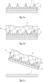
- FIG. 1a To illustrate the first embodiment of a method according to the invention, a section of the outer skin of a commercial aircraft is shown as surface 1, on which, with the aid of a transfer film (not shown), individual riblets 3 are applied, which, although not directly connected to one another, together form a film-like coating 2 to be removed in the sense of the present invention.
- a stripping compound 5 is first applied as a stripping agent 6 to the coating 2 ( Figure 1b ) and then pressed onto the coating 2 or the surface 1. Since the release liner 5 is deformable and self-adhesive on the side facing the surface 1, a large or full-surface material bond is achieved between the release liner 5 and the coating 2 ( Figure 1c ).
- the self-adhesive property of the release liner 5 is selected such that the material bond between the release liner 5 and the coating 2 is stronger than the bond between the coating 2 and the surface 1.
- the material bond between the release liner 5 and the surface 1 in the areas of the coating 2 between the individual riblets 3 should be sufficiently low so as not to subsequently damage the varnish that regularly forms the outermost layer of the surface 1.
- the release compound 5 can be removed as a stripping agent 6 from the surface 1, whereby due to the above-described relationships of the individual connections between surface 1, coating 2 and release compound 5, the coating 2 adheres to the stripping agent 6 and is thus removed from the surface 1 ( Figure 1d ).
- FIG 2 A second embodiment of the method according to the invention is shown.
- a basically continuous film with a microstructured surface comprising riblets 3 is arranged as a coating 2, which is to be removed ( Figure 2a ).
- the release agent 6 On the side facing away from the surface 1, the release agent 6 has a release film 7 which is permanently connected to the release compound 5 or is integrally formed therewith, which increases the tensile strength of the release agent 6 in order to Figure 2d to facilitate the outlined removal of the release agent 6 together with the coating 2 adhering to it.
- Figure 3 illustrates a third embodiment of a method according to the invention.
- the coating 2 with riblets 3 is attached to the surface 1 - the outer skin of an aircraft - by means of a carrier film 4, whereby the connection between the coating 2 and the carrier film 4 is stronger than the connection between the carrier film 4 and the surface 1.
- a hardening gel-like substance 8 is applied to the coating 2 as the stripping agent 6, which, when hardened, bonds firmly with the film 2 to be removed ( Figure 3b ).
- the resulting material bond between the stripping agent 6 and the coating 2 is stronger than the bond between the coating 2 and the surface 1, so that when the stripping agent 6 is removed, the coating 2 adheres to the substance 8 after it has completely hardened. and is thus removed together with the carrier film 4 from the surface 1 ( Figure 3c ).
Landscapes
- Engineering & Computer Science (AREA)
- Manufacturing & Machinery (AREA)
- Transportation (AREA)
- Aviation & Aerospace Engineering (AREA)
- Application Of Or Painting With Fluid Materials (AREA)
- Mechanical Treatment Of Semiconductor (AREA)
- Separation, Recovery Or Treatment Of Waste Materials Containing Plastics (AREA)
Description
- Die Erfindung betrifft ein Verfahren zur Entfernung von Überzügen von Oberflächen, insbesondere von durch Umwelteinflüsse versprödeten Überzügen von Oberflächen.
- Das Anbringen von Überzügen, bspw. in Form von selbstklebenden Folien, auf Oberflächen wie bspw. der Außenhaut von Flugzeugen ist im Stand der Technik für verschiedene Anwendungszwecke bekannt. Neben dem Anbringen von Logos, Schriftzügen oder sonstigen grafischen Elementen durch entsprechend ausgestaltete Folien, kommen vermehrt auch aerodynamisch funktionale Folien zum Einsatz.
- Aerodynamisch funktionalen Folien sind in unterschiedlichen Ausprägungen und Anwendungsbereichen aus dem Stand der Technik bekannt, und dienen regelmäßig dazu, die Wandschubspannung auf Oberflächen von umströmten Körpern zu reduzieren. Die aerodynamisch funktionalen Folien weisen dazu in der Regel eine mikrostrukturierte Oberfläche auf. Eine verbreitete Mikrostruktur ist dabei die sog. Riblet-Struktur, mit sehr kleinen, im Wesentlichen entlang der Hauptströmungsrichtung verlaufenden Rippen. Werden entsprechende Riblet-Strukturen auf die Außenhaut eines Flugzeugs aufgebracht, kann dadurch der Strömungswiderstand des Flugzeugs und so der Treibstoffverbrauch reduziert werden.
- Für die Anbringung an der Außenhaut eines Flugzeuges vorgesehenen Folien sind aus Gewichtsgründen regelmäßig dünn ausgeführt. Gleichzeitig sind sie erheblichen Umwelteinflüssen ausgesetzt. Neben der Überströmung mit Luft, in der Partikel, wie Sand oder Eis, mitgeführt werden und die Folie oder deren aerodynamisch funktionaler Oberfläche mechanisch beschädigen können, ist die Folie insbesondere bei Verkehrsflugzeugen in Reiseflughöhe regelmäßig intensiver Sonnenbestrahlung ausgesetzt.
- Aufgrund der in der Praxis auftretenden Beschädigungen sind insbesondere aerodynamisch funktionale Folien regelmäßig zu ersetzen. Es hat sich aber gezeigt, dass aufgrund der geringen Dicke sowie des aufgrund der intensiven Bestrahlung mit Sonnenlicht im Betrieb eines Flugzeugs spröde Werdens das Entfernen von auf die Außenhaut eines Flugzeugs aufgebrachter Folie häufig schwierig ist. Das vollständige und rückstandslose Entfernen, ohne dass dabei die Außenhaut beschädigt wird, ist derzeit nur mit manuell durchzuführenden chemischen oder mechanischen Verfahren möglich, die sehr zeitaufwendig sind. Auch können bei entsprechenden Verfahren gesundheits- oder umweltgefährdende Stäube und/oder Chemikalienreste entstehen.
- Vergleichbares gilt auch für solche Überzüge, bei denen Lack auf die Oberfläche aufgebracht und in die bspw. eine gewünschte Mikrostruktur eingeprägt ist. Auch diese können verspröden und müssen für eine evtl. Erneuerung erst mühsam entfernt werden.
- Neben der beschriebenen Anwendung auf der Außenhaut von Flugzeugen kommen entsprechende Überzüge auch auf anderen Oberflächen zum Einsatz, bspw. an den Rotorblättern von Windenergieanlagen oder an Hochgeschwindigkeitszügen, wo sie jedoch vergleichbaren Umwelteinflüssen ausgesetzt sind und nach Beschädigung ebenfalls entfernt werden müssen, bevor sie erneuter werden können.
- Das Dokument
WO 2012/058729 beschreibt ein Verfahren zum Entfernen von unerwünschten Graffitis, bei dem ein zu schützendes Substrat mit einer transparenten Opferschicht versehen ist, auf der ein mögliches Graffiti aufgetragen wird. Durch Anbringen einer Klebeschicht, deren Adhäsion an der Opferschicht größer ist als diejenige der Opferschicht am Substrat, und anschließendes Abziehen der Klebeschicht kann die Opferschicht zusammen mit den darauf befindlichen Graffiti entfernt werden. Das DokumentDE 10 2015 204 254 A1 beschreibt ein Verfahren zum Entfernen von Tinte, Farbe und/oder Lacke von Oberflächen, bei dem die Haftung der Tinte mit einem Reinigungsmittel gemindert wird, bevor anschließend ein Klebestreifen darauf angepresst und unmittelbar wieder abgezogen wird. Die Tinte soll dann aufgrund der bereits reduzierten Haftung auf der Oberfläche an dem Klebestreifen anhaften und so entfernt werden können. - In Dokument
US 2014/0272237 A1 ist eine Riblet-Folie offenbart, die für organisches Reinigungsmittel derart durchlässig sein soll, dass durch den oberflächlichen Auftrag von entsprechendem Reinigungsmittel die Klebeverbindung mit der darunterliegenden Oberfläche gelöst werden kann. - Aufgabe der vorliegenden Erfindung ist es daher, ein gegenüber dem Stand der Technik verbessertes Verfahren zur Entfernung von Überzügen, insbesondere von durch Umwelteinflüsse versprödete Überzügen, von Oberflächen zu schaffen.
- Gelöst wird diese Aufgabe durch ein Verfahren gemäß dem Hauptanspruch 1, bzw. 3. Weiterbildungen sind Gegenstand der abhängigen Ansprüche.
- Demnach betrifft die Erfindung gemäß Anspruch 1 ein Verfahren zur Entfernung von Überzügen von Oberflächen, umfassend die Schritte:
- großflächiges Aufbringen eines geeignet gewählten Abziehmittels auf den abzulösenden Überzug zur Herstellung einer stoffschlüssigen Verbindung, sodass die Verbindung zwischen Abziehmittel und abzulösendem Überzug stärker ist als die Verbindung zwischen abzulösendem Überzug und der Oberfläche, wobei das Abziehmittel eine wenigstens einseitig selbstklebende, flächige Abziehmasse ist, die Abziehmasse in Anpressrichtung verformbar ist und die zum Aufbringen mit einer selbstklebenden Seite auf den abzulösenden Überzug gedrückt wird, und wobei der abzuziehende Überzug eine mikrostrukturierte Oberfläche aufweist; und
- Abziehen des Abziehmittels mitsamt dem daran anhaftenden abzulösenden Überzug.
- Des Weiteren betrifft die Erfindung gemäß Anspruch 3 ein Verfahren zur Entfernung von Überzügen von Oberflächen, umfassend die Schritte:
- großflächiges Aufbringen eines geeignet gewählten Abziehmittels auf dem abzulösenden Überzug zur Herstellung einer stoffschlüssigen Verbindung, sodass die Verbindung zwischen Abziehmittel und abzulösendem Überzug stärker ist als die Verbindung zwischen abzulösendem Überzug und der Oberfläche, wobei das Abziehmittel eine aushärtbare Substanz ist, welche sich beim Aushärten mit dem abzulösenden Überzug verbindet und welche im Ausgangszustand flüssig ist, wobei der abzuziehende Überzug eine mikrostrukturierte Oberfläche aufweist; und
- Abziehen des Abziehmittels mitsamt dem daran anhaftenden abzulösenden Überzug.
- Zunächst werden einige im Rahmen der Erfindung verwendete Begriffe erläutert.
- Eine erste Verbindung ist "stärker" als eine zweite Verbindung, wenn die erste Verbindung einer Belastung, bei der die zweite Verbindung versagt, standhält. Im Fall von Klebeverbindungen ist bspw. die Haftkraft der ersten Verbindung FH1, die überwunden werden muss, um die erste Verbindung zu lösen, größer als die Haftkraft der zweiten Verbindung FH2 (FH1 > FH2).
- Umgekehrt gilt eine erste Verbindung als "schwächer" als eine zweite Verbindung, wenn die erste Verbindung bei identischer Belastung nachgibt, während die zweite Verbindung noch Bestand hat. Im Fall von Klebeverbindungen ist die Haftkraft der ersten Verbindung FH1 kleiner als die Haftkraft der zweiten Verbindung FH2 (FH1 < FH2).
- Die Erfindung hat erkannt, dass sich ein auf einer Oberfläche angebrachter Überzug, der sich nicht ohne Weiteres unmittelbar abziehen lässt, insbesondere weil er aufgrund von Umwelteinflüssen spröde geworden bzw. "versprödet" ist, entfernen lässt, wenn zunächst ein Abziehmittel aufgebracht wird, welches sich derart stark mit dem abzulösenden Überzug verbindet, dass bei einem anschließenden Abziehen des Abziehmittels der Überzug an dem Ablösemittel anhaftet und somit zusammen mit dem Abziehmittel abgezogen wird. Die für das Abziehen erforderliche Zugfestigkeit kann dabei allein durch das Abziehmittel hergestellt werden, sodass es auf die Zugfestigkeit des abzuziehenden Überzugs und/oder dessen Versprödungsgrad nicht mehr ankommt.
- Damit der abzulösende Überzug beim Abziehen des Abziehmittels auch tatsächlich an dem Abziehmittel anhaftet und folglich von der Oberfläche entfernt wird, ist es erforderlich, dass die Verbindung zwischen Abziehmittel und abzulösendem Überzug stärker ist, als die Verbindung zwischen abzulösendem Überzug und der Oberfläche. Die Wahl eines geeigneten Abziehmittels ist bei Vorliegen ausreichender Informationen zur Verbindung des abzuziehenden Überzugs mit der Oberfläche, bspw. zu dem verwendeten Klebstoff, problemlos möglich, lässt sich aber auch durch einfache Versuche unmittelbar an dem abzulösenden Überzug ermitteln.
- Bei dem Abziehmittel handelt es sich gemäß einem Aspekt der Erfindung um eine wenigstens einseitig selbstklebende, flächige Abziehmasse, die zum Aufbringen mit einer selbstklebenden Seite auf den abzulösenden Überzug gedrückt wird. Durch das Andrücken wird die gewünschte und für das weitere Verfahren erforderliche stoffschlüssige Verbindung zwischen Abziehmasse und abzulösendem Überzug hergestellt.
- Grundsätzlich kann es sich bei der Abziehmasse um eine selbstklebende Abziehfolie handeln. Um jedoch eine flächige Verbindung zwischen der Abziehmasse und dem abzulösenden Überzug auch bei Beschädigungen und/oder Mikrostrukturierungen der Oberfläche des abzulösenden Überzugs herstellen zu können, ist die Abziehmasse in Anpressrichtung verformbar. Wird die Abziehmasse dann an den abzuziehenden Überzug angedrückt, kann sie sich an diese anschmiegen und vollflächig mit dieser verbinden, unabhängig davon, ob eine Beschädigung und/oder Mikrostrukturierung der Oberfläche des abzuziehenden Überzugs vorliegt. Die Abziehmasse kann dabei plastisch und/oder elastisch verformbar sein.
- Insbesondere bei verformbaren Abziehmassen kann die Zugfestigkeit der Abziehmasse evtl. nicht ausreichend sein, um die Abziehmasse zusammen mit daran anhaftendem Überzug von der Oberfläche problemlos abziehen zu können. Es ist insbesondere in diesen Fällen bevorzugt, wenn die Abziehmasse auf der von dem abzulösenden Überzug entfernten Seite eine zugfeste Abziehschicht, vorzugsweise eine Abziehfolie, aufweist. Mit einer entsprechenden Abziehschicht kann die Zugfestigkeit der Abziehmasse erhöht werden, um das erfindungsgemäß vorgesehene Abziehen des Abziehmittels mitsamt dem daran anhaftenden abzulösenden Überzug zu ermöglichen.
- Alternativ zur Verwendung einer Abziehmasse als Abziehmittel ist gemäß einem weiteren Aspekt der Erfindung eine aushärtbare Substanz als Abziehmittel vorgesehen sein, welche sich beim Aushärten mit dem abzulösenden Überzug stoffschlüssig verbindet. Nach dem Aushärten bildet die Substanz ein zum Abziehen mitsamt dem daran anhaftenden abzulösenden Überzug geeignetes Abziehmittel.
- Die aushärtbare Substanz ist dabei im Ausgangszustand flüssig. Ein großflächiges Aufbringen der Substanz auf einen abzulösenden Überzug ist damit einfach möglich. Nach dem Aushärten ist die Substanz fest.
- In die noch nicht-ausgehärtete Substanz kann auch ein Netz oder ein Textil großflächig eingebracht werden, welches von der noch nicht-ausgehärteten Substanz vollständig umschlossen wird. Nach dem Aushärten der Substanz kann das Netz bzw. das Textil die Zugfestigkeit des Abziehmittels erhöhen.
- Unabhängig, wie das Abziehmittel gebildet ist, ist es bevorzugt, wenn es derart gewählt ist, dass eine evtl. Verbindung zwischen Abziehmittel und der Oberfläche schwächer ist als die Verbindung zwischen Abziehmittel und abzulösendem Überzug. Weiter ist bevorzugt, wenn eine evtl. Verbindung zwischen Abziehmittel und der Oberfläche auch schwächer ist als die Verbindung zwischen abzulösendem Überzug und der Oberfläche. Dadurch wird erreicht, dass auch bei planvollen Auslassungen in dem abzuziehenden Überzug oder erheblichen Beschädigungen des abzulösenden Überzugs, in deren Bereich das Abziehmittel beim Andrücken in unmittelbaren Kontakt mit der Oberfläche kommt, das Abziehen des Abziehmittels problemlos und insbesondere auch beschädigungsfrei für die Oberfläche möglich ist.
- Die erfindungsgemäßen Verfahren haben sich als besonders gut geeignet für das Abziehen von Überzügen mit mikrostrukturierter Oberfläche erwiesen. Dies gilt insbesondere, wenn der Überzug eine Riblet-Struktur aufweist - also eine Riblet-förmige Oberflächenstrukturierung. Da es bei den erfindungsgemäßen Verfahren zum Ablösen des Überzugs nicht auf die Zugfestigkeit des
- Überzugs selbst ankommt, kann der abzulösende Überzug besonders dünn und somit leicht ausgestaltet werden und insbesondere ohne im Stand der Technik häufig ansonsten vorgesehen, zugfeste Zusatzschichten auskommen.
- Der abzuziehende Überzug kann eine auf die Oberfläche aufgeklebte Folie oder eine auf die Oberfläche aufgetragene Lackschicht sein, jeweils ggf. mit darin eingeprägter mikrostrukturierter Oberfläche. Bei der Oberfläche kann es sich insbesondere die Außenhaut eines Flugzeugs, eines Hochgeschwindigkeitszuges oder eines Windenergieanlagenrotorblatts handeln.
- Die Erfindung wird nun anhand bevorzugter Ausführungsformen unter Bezugnahme auf die beigefügten Zeichnungen beispielhaft beschrieben. Es zeigen:
- Figur 1a-d:
- eine schematische Darstellung eines ersten Ausführungsbeispiels eines erfindungsgemäßen Verfahrens;
- Figur 2a-d:
- eine schematische Darstellung eines zweiten Ausführungsbeispiels eines erfindungsgemäßen Verfahrens; und
- Figur 3a-c:
- eine schematische Darstellung eines dritten Ausführungsbeispiels eines erfindungsgemäßen Verfahrens.
- In
Figur 1a ist zur Illustration des ersten Ausführungsbeispiels eines erfindungsgemäßen Verfahrens ein Abschnitt der Außenhaut eines Verkehrsflugzeuges als Oberfläche 1 dargestellt, auf der mithilfe einer Transferfolie (nicht dargestellt) einzelne Riblets 3, die, wenn auch nicht untereinander unmittelbar verbunden, zusammen einen abzulösenden folienartigen Überzug 2 im Sinne der vorliegenden Erfindung bilden. - Zum Ablösen des Überzugs 2 wird zunächst eine Abziehmasse 5 als Abziehmittel 6 auf den Überzug 2 aufgebracht (
Figur 1b ) und anschließend an den Überzug 2 bzw. die Oberfläche 1 angedrückt. Da die Abziehmasse 5 verformbar und auf der, der Oberfläche 1 zugewandten Seite selbstklebend ist, wird so eine groß- bzw. vollflächige stoffschlüssige Verbindung zwischen Abziehmasse 5 und Überzug 2 erreicht (Figur 1c ). Dabei ist die selbstklebende Eigenschaft der Abziehmasse 5 so gewählt, dass die stoffschlüssige Verbindung zwischen Abziehmasse 5 und Überzug 2 stärker ist, als die Verbindung zwischen Überzug 2 und Oberfläche 1. Gleichzeitig soll die stoffschlüssige Verbindung zwischen Abziehmasse 5 und Oberfläche 1 in den Bereichen des Überzugs 2 zwischen den einzelnen Riblets 3 ausreichend gering sein, um den die äußerste Schicht der Oberfläche 1 regelmäßig bildenden Lack im nachfolgenden nicht zu beschädigen. - Ist die Abziehmasse 5 vollständig aufgebracht und angedrückt, kann die Abziehmasse 5 als Abziehmittel 6 von der Oberfläche 1 abgezogen werden, wobei aufgrund der vorstehend beschriebenen Verhältnisse der einzelnen Verbindungen zwischen Oberfläche 1, Überzug 2 und Abziehmasse 5 der Überzug 2 an dem Abziehmittel 6 anhaftet und so von der Oberfläche 1 entfernt wird (
Figur 1d ). - In
Figur 2 ist ein zweites Ausführungsbeispiel des erfindungsgemäßen Verfahrens dargestellt. Auf der Oberfläche 1 - bspw. der Außenhaut eines Flugzeugs - ist eine grundsätzlich durchgehende Folie mit mikrostrukturierter Oberfläche umfassend Riblets 3 als Überzug 2 angeordnet, die entfernt werden soll (Figur 2a ). - Zum Ablösen des Überzugs 2 wird - vergleichbar zum Ausführungsbeispiel gemäß
Figur 1 - zunächst eine Abziehmasse 5 als Abziehmittel 6 mit ihrer selbstklebenden Seite auf den Überzug 2 aufgebracht (Figur 2b ) und anschließend an den Überzug 2 bzw. die Oberfläche 1 angedrückt, sodass sich eine stoffschlüssige Verbindung zwischen Abziehmittel 6 und Überzug 2 ergibt (Figur 2c ). Die Eigenschaften der Verbindung im Verhältnis zur Verbindung zwischen Überzug 2 und Oberfläche 1 entsprechen dabei dem vorhergehenden Ausführungsbeispiel, weshalb auf die entsprechenden Ausführungen verwiesen wird. - Auf der der Oberfläche 1 abgewandten Seite weist das Abziehmittel 6 ein unlösbar mit der Abziehmasse 5 verbundene bzw. integral damit ausgeführte Abziehfolie 7 auf, welche die Zugfestigkeit des Abziehmittels 6 erhöht, um so das in
Figur 2d skizzierte Abziehen des Abziehmittels 6 mitsamt dem daran anhaftenden Überzug 2 zu erleichtern. -
Figur 3 illustriert ein drittes Ausführungsbeispiel eines erfindungsgemäßen Verfahrens. - Der in diesem Beispiel Überzug 2 mit Riblets 3 ist mithilfe einer Trägerfolie 4 an der Oberfläche 1 - der Außenhaut eines Flugzeugs - befestigt, wobei die Verbindung zwischen Überzug 2 und Trägerfolie 4 stärker ist als die Verbindung zwischen Trägerfolie 4 und Oberfläche 1.
- Als Abziehmittel 6 wird in diesem Ausführungsbeispiel eine aushärtende gelartige Substanz 8 auf den Überzug 2 aufgebracht, die sich beim Aushärten mit der abzulösenden Folie 2 stoffschlüssig verbindet (
Figur 3b ). Die so entstehende stoffschlüssige Verbindung zwischen Abziehmittel 6 und Überzug 2 ist stärker als die Verbindung zwischen Überzug 2 und Oberfläche 1, sodass der Überzug 2 beim Abziehen des Abziehmittels 6 nach vollständigem Aushärten der Substanz 8 an diesem anhaftet und so mitsamt der Trägerfolie 4 von der Oberfläche 1 entfernt wird (Figur 3c ).
Claims (7)
- Verfahren zur Entfernung von Überzügen (2) von Oberflächen (1), umfassend die Schritte:- großflächiges Aufbringen eines geeignet gewählten Abziehmittels (6) auf dem abzulösenden Überzug (2) zur Herstellung einer stoffschlüssigen Verbindung, sodass die Verbindung zwischen Abziehmittel (5) und abzulösendem Überzug (2) stärker ist als die Verbindung zwischen abzulösendem Überzug (2) und der Oberfläche (1), wobei das Abziehmittel (6) eine wenigstens einseitig selbstklebende, flächige Abziehmasse (5) ist, die Abziehmasse (5) in Anpressrichtung verformbar ist und die zum Aufbringen mit einer selbstklebenden Seite auf den abzulösenden Überzug (2) gedrückt wird, und wobei der abzuziehende Überzug (2) eine mikrostrukturierte Oberfläche aufweist; und- Abziehen des Abziehmittels (6) mitsamt dem daran anhaftenden abzulösenden Überzug (2).
- Verfahren nach Anspruch 1,
dadurch gekennzeichnet, dass
die Abziehmasse (5) auf der von dem abzulösenden Überzug (2) entfernten Seite eine zugfeste Abziehschicht, vorzugsweise eine Abziehfolie (7), aufweist. - Verfahren zur Entfernung von Überzügen (2) von Oberflächen (1), umfassend die Schritte:- großflächiges Aufbringen eines geeignet gewählten Abziehmittels (6) auf dem abzulösenden Überzug (2) zur Herstellung einer stoffschlüssigen Verbindung, sodass die Verbindung zwischen Abziehmittel (5) und abzulösendem Überzug (2) stärker ist als die Verbindung zwischen abzulösendem Überzug (2) und der Oberfläche (1), wobei das Abziehmittel (6) eine aushärtbare Substanz (8) ist, welche im Ausgangszustand flüssig ist und sich beim Aushärten mit dem abzulösenden Überzug (2) verbindet, und wobei der abzuziehende Überzug (2) eine mikrostrukturierte Oberfläche aufweist; und- Abziehen des Abziehmittels (6) mitsamt dem daran anhaftenden abzulösenden Überzug (2).
- Verfahren nach einem der vorhergehenden Ansprüche,
dadurch gekennzeichnet, dass
das Abziehmittel (6) derart gewählt ist, dass eine evtl. Verbindung zwischen Abziehmittel (6) und der Oberfläche (1) schwächer ist als die Verbindung zwischen Abziehmittel (6) und abzulösendem Überzug (2), vorzugsweise schwächer als die Verbindung zwischen abzulösendem Überzug (2) und der Oberfläche (1). - Verfahren nach einem der vorhergehenden Ansprüche,
dadurch gekennzeichnet, dass
der abzuziehende Überzug (2) eine Riblet-Struktur (3) umfasst. - Verfahren nach einem der vorhergehenden Ansprüche,
dadurch gekennzeichnet, dass
der abzuziehende Überzug (2) eine auf die Oberfläche (1) aufgeklebte Folie oder eine auf die Oberfläche (1) aufgetragene Lackschicht ist. - Verfahren nach einem der vorhergehenden Ansprüche,
dadurch gekennzeichnet, dass
die Oberfläche (1) die Außenhaut eines Flugzeugs, eines Hochgeschwindigkeitszuges oder eines Windenergieanlagenrotorblatts ist.
Applications Claiming Priority (2)
| Application Number | Priority Date | Filing Date | Title |
|---|---|---|---|
| DE102020108713.6A DE102020108713A1 (de) | 2020-03-30 | 2020-03-30 | Verfahren zur Entfernung von Überzügen von Oberflächen |
| PCT/EP2021/058243 WO2021198225A1 (de) | 2020-03-30 | 2021-03-30 | Verfahren zur entfernung von überzügen von oberflächen |
Publications (2)
| Publication Number | Publication Date |
|---|---|
| EP4126402A1 EP4126402A1 (de) | 2023-02-08 |
| EP4126402B1 true EP4126402B1 (de) | 2025-01-01 |
Family
ID=75438720
Family Applications (1)
| Application Number | Title | Priority Date | Filing Date |
|---|---|---|---|
| EP21717337.6A Active EP4126402B1 (de) | 2020-03-30 | 2021-03-30 | Verfahren zur entfernung von überzügen von oberflächen |
Country Status (10)
| Country | Link |
|---|---|
| US (1) | US20230166304A1 (de) |
| EP (1) | EP4126402B1 (de) |
| CN (1) | CN115515727B (de) |
| AU (1) | AU2021246883B2 (de) |
| BR (1) | BR112022019475A2 (de) |
| DE (1) | DE102020108713A1 (de) |
| ES (1) | ES3016969T3 (de) |
| PL (1) | PL4126402T3 (de) |
| PT (1) | PT4126402T (de) |
| WO (1) | WO2021198225A1 (de) |
Family Cites Families (19)
| Publication number | Priority date | Publication date | Assignee | Title |
|---|---|---|---|---|
| US3531311A (en) * | 1967-10-31 | 1970-09-29 | Apyrco Inc | Method of applying gelled water soluble coatings as parting agents |
| JPH06260465A (ja) * | 1993-03-05 | 1994-09-16 | Nippon Steel Corp | 表面処理方法 |
| JP2881558B2 (ja) * | 1995-07-12 | 1999-04-12 | 本田技研工業株式会社 | 一時保護塗膜の剥離方法 |
| JP3107030B2 (ja) | 1997-03-14 | 2000-11-06 | 鹿島建設株式会社 | 構造物表面の洗浄方法 |
| CA2313375A1 (en) * | 2000-07-04 | 2002-01-04 | E.Q.U.I.P. International Inc. | Method for removing paint using a barrier film |
| US6776171B2 (en) * | 2001-06-27 | 2004-08-17 | International Business Machines Corporation | Cleaning of semiconductor wafers by contaminate encapsulation |
| JP2004323841A (ja) * | 2003-04-10 | 2004-11-18 | Kansai Paint Co Ltd | 被膜の剥離液及び被膜の剥離方法 |
| US7229953B1 (en) * | 2004-10-25 | 2007-06-12 | Green Oaks Research Laboratories, Inc. | Process for removing a coating from a substrate |
| FR2881681B1 (fr) * | 2005-02-08 | 2007-04-27 | Stanislas Chevallier | Procedes d'application d'un film decoratif sur un support, et procedes de preparation d'articles a cet effet |
| JP2006344618A (ja) * | 2005-06-07 | 2006-12-21 | Fujifilm Holdings Corp | 機能性膜含有構造体、及び、機能性膜の製造方法 |
| US8361947B2 (en) * | 2007-04-30 | 2013-01-29 | Peel Away Limited | Paint remover |
| DE102009034169A1 (de) | 2009-07-22 | 2011-02-03 | Bruno Gruber | Etikettenablöser |
| GB201012737D0 (en) * | 2010-07-29 | 2010-09-15 | Airbus Operations Ltd | Improvements to aircraft refuel system piping |
| WO2012058729A1 (en) * | 2010-11-05 | 2012-05-10 | Vipond's Paints Proprietary Limited | Removal of markings off a substrate |
| US20140272237A1 (en) * | 2013-03-15 | 2014-09-18 | Prc-Desoto International, Inc. | Strippable film assembly and coating for drag reduction |
| CN104941959B (zh) * | 2014-03-27 | 2020-05-19 | 海德堡印刷机械股份公司 | 利用胶条去除硬化的墨、涂料或漆的方法 |
| US10734255B2 (en) * | 2016-05-25 | 2020-08-04 | Tokyo Electron Limited | Substrate cleaning method, substrate cleaning system and memory medium |
| DE102016220437A1 (de) | 2016-10-19 | 2018-04-19 | Airbus Defence and Space GmbH | Reinigungsanordnung für Tragflächenvorderkanten |
| US11952512B2 (en) * | 2020-05-08 | 2024-04-09 | The Boeing Company | Chemical process for stripping surfaces |
-
2020
- 2020-03-30 DE DE102020108713.6A patent/DE102020108713A1/de active Pending
-
2021
- 2021-03-30 PL PL21717337.6T patent/PL4126402T3/pl unknown
- 2021-03-30 ES ES21717337T patent/ES3016969T3/es active Active
- 2021-03-30 US US17/916,035 patent/US20230166304A1/en not_active Abandoned
- 2021-03-30 EP EP21717337.6A patent/EP4126402B1/de active Active
- 2021-03-30 BR BR112022019475A patent/BR112022019475A2/pt not_active Application Discontinuation
- 2021-03-30 AU AU2021246883A patent/AU2021246883B2/en active Active
- 2021-03-30 WO PCT/EP2021/058243 patent/WO2021198225A1/de not_active Ceased
- 2021-03-30 PT PT217173376T patent/PT4126402T/pt unknown
- 2021-03-30 CN CN202180033477.8A patent/CN115515727B/zh active Active
Also Published As
| Publication number | Publication date |
|---|---|
| CA3174028A1 (en) | 2021-10-07 |
| PT4126402T (pt) | 2025-03-27 |
| CN115515727B (zh) | 2025-01-21 |
| CN115515727A (zh) | 2022-12-23 |
| DE102020108713A1 (de) | 2021-09-30 |
| BR112022019475A2 (pt) | 2022-11-16 |
| US20230166304A1 (en) | 2023-06-01 |
| AU2021246883A1 (en) | 2022-10-27 |
| EP4126402A1 (de) | 2023-02-08 |
| ES3016969T3 (en) | 2025-05-12 |
| WO2021198225A1 (de) | 2021-10-07 |
| PL4126402T3 (pl) | 2025-06-16 |
| AU2021246883B2 (en) | 2024-06-20 |
Similar Documents
| Publication | Publication Date | Title |
|---|---|---|
| DE3686445T2 (de) | Einrichtung zur verringerung des luftwiderstandes. | |
| DE102008042237A1 (de) | Metallische Beschichtung | |
| EP3069858A1 (de) | Verfahren und Vorrichtung zur Herstellung eines Windenergieanlagenbauteils aus einem Faserverbundwerkstoff | |
| WO2008040322A2 (de) | Deformierbares substrat mit mikrostrukturierter oberfläche aus aufgebrachtem material sowie verfahren zur herstellung eines solchen substrates | |
| DE102020004438A1 (de) | Befestigungssystem | |
| DE102020113705A1 (de) | Verfahren zum herstellen eines bauteils und bauteil | |
| DE202007004631U1 (de) | Sanierungspacker mit Inliner-Matte | |
| DE102012015183A1 (de) | Fügeverbindung zwischen zwei Bauteilen, Blindniet für eine solche Fügeverbindung sowie Verfahren zur Herstellung einer solchen Fügeverbindung | |
| DE102019121563A1 (de) | Verfahren zur Herstellung eines Bauteils sowie Bauteil hierzu | |
| EP2463537B1 (de) | Korrosionsgeschütztes Lager | |
| WO2021198225A1 (de) | Verfahren zur entfernung von überzügen von oberflächen | |
| DE102016003008A1 (de) | Komprimierbares Montageband und dessen Verwendung | |
| DE102012014659A1 (de) | Kunststoffbauteil, insbesondere für ein Kraftfahrzeug und Verfahren zur Herstellung eines Kunststoffbauteils | |
| EP1695768B1 (de) | Verfahren zum temporären Schützen blanker Oberflächen gegen Korrosion und Bauteil mit temporärem Korrosionsschutz | |
| EP3929360B1 (de) | Schachtabdeckungssystem, sowie verfahren zur trennung eines deckbelags von einer schachtabdeckung | |
| WO2022128148A1 (de) | Verfahren zur aufbringung von prägestrukturen auf eine oberfläche eines objekts | |
| EP2730628B1 (de) | Flächengebilde | |
| DE102019121564A1 (de) | Verfahren zur Herstellung eines Bauteils sowie Bauteil hierzu | |
| DE102008057456A1 (de) | Sicherheitsetikett | |
| WO2010089050A1 (de) | Wert- und/oder sicherheitsdokument und verfahren zur herstellung desselben | |
| DE102019101485A1 (de) | Riblet-Folie und Verfahren zu deren Herstellung | |
| HK40088905A (en) | Method for removing coatings from surfaces | |
| DE10150247B4 (de) | Außenhaut eines fluidumströmten Körpers, Verfahren zu deren Herstellung | |
| DE102022003832B4 (de) | Klebeverbund und Trennverfahren | |
| DE202004010576U1 (de) | Anordnung zum dauerhaften partiellen Abdecken von klebenden Bahnen und klebende Bahn |
Legal Events
| Date | Code | Title | Description |
|---|---|---|---|
| STAA | Information on the status of an ep patent application or granted ep patent |
Free format text: STATUS: UNKNOWN |
|
| STAA | Information on the status of an ep patent application or granted ep patent |
Free format text: STATUS: THE INTERNATIONAL PUBLICATION HAS BEEN MADE |
|
| PUAI | Public reference made under article 153(3) epc to a published international application that has entered the european phase |
Free format text: ORIGINAL CODE: 0009012 |
|
| STAA | Information on the status of an ep patent application or granted ep patent |
Free format text: STATUS: REQUEST FOR EXAMINATION WAS MADE |
|
| 17P | Request for examination filed |
Effective date: 20221013 |
|
| AK | Designated contracting states |
Kind code of ref document: A1 Designated state(s): AL AT BE BG CH CY CZ DE DK EE ES FI FR GB GR HR HU IE IS IT LI LT LU LV MC MK MT NL NO PL PT RO RS SE SI SK SM TR |
|
| P01 | Opt-out of the competence of the unified patent court (upc) registered |
Effective date: 20230516 |
|
| DAV | Request for validation of the european patent (deleted) | ||
| DAX | Request for extension of the european patent (deleted) | ||
| REG | Reference to a national code |
Ref country code: HK Ref legal event code: DE Ref document number: 40088905 Country of ref document: HK |
|
| GRAP | Despatch of communication of intention to grant a patent |
Free format text: ORIGINAL CODE: EPIDOSNIGR1 |
|
| STAA | Information on the status of an ep patent application or granted ep patent |
Free format text: STATUS: GRANT OF PATENT IS INTENDED |
|
| INTG | Intention to grant announced |
Effective date: 20240902 |
|
| GRAS | Grant fee paid |
Free format text: ORIGINAL CODE: EPIDOSNIGR3 |
|
| GRAA | (expected) grant |
Free format text: ORIGINAL CODE: 0009210 |
|
| STAA | Information on the status of an ep patent application or granted ep patent |
Free format text: STATUS: THE PATENT HAS BEEN GRANTED |
|
| AK | Designated contracting states |
Kind code of ref document: B1 Designated state(s): AL AT BE BG CH CY CZ DE DK EE ES FI FR GB GR HR HU IE IS IT LI LT LU LV MC MK MT NL NO PL PT RO RS SE SI SK SM TR |
|
| REG | Reference to a national code |
Ref country code: GB Ref legal event code: FG4D Free format text: NOT ENGLISH |
|
| REG | Reference to a national code |
Ref country code: DE Ref legal event code: R096 Ref document number: 502021006274 Country of ref document: DE |
|
| REG | Reference to a national code |
Ref country code: CH Ref legal event code: EP |
|
| REG | Reference to a national code |
Ref country code: IE Ref legal event code: FG4D Free format text: LANGUAGE OF EP DOCUMENT: GERMAN |
|
| REG | Reference to a national code |
Ref country code: PT Ref legal event code: SC4A Ref document number: 4126402 Country of ref document: PT Date of ref document: 20250327 Kind code of ref document: T Free format text: AVAILABILITY OF NATIONAL TRANSLATION Effective date: 20250321 |
|
| REG | Reference to a national code |
Ref country code: NL Ref legal event code: FP |
|
| REG | Reference to a national code |
Ref country code: LT Ref legal event code: MG9D |
|
| REG | Reference to a national code |
Ref country code: SK Ref legal event code: T3 Ref document number: E 46124 Country of ref document: SK |
|
| REG | Reference to a national code |
Ref country code: ES Ref legal event code: FG2A Ref document number: 3016969 Country of ref document: ES Kind code of ref document: T3 Effective date: 20250512 |
|
| PG25 | Lapsed in a contracting state [announced via postgrant information from national office to epo] |
Ref country code: FI Free format text: LAPSE BECAUSE OF FAILURE TO SUBMIT A TRANSLATION OF THE DESCRIPTION OR TO PAY THE FEE WITHIN THE PRESCRIBED TIME-LIMIT Effective date: 20250101 |
|
| PGFP | Annual fee paid to national office [announced via postgrant information from national office to epo] |
Ref country code: ES Payment date: 20250416 Year of fee payment: 5 |
|
| PG25 | Lapsed in a contracting state [announced via postgrant information from national office to epo] |
Ref country code: IS Free format text: LAPSE BECAUSE OF FAILURE TO SUBMIT A TRANSLATION OF THE DESCRIPTION OR TO PAY THE FEE WITHIN THE PRESCRIBED TIME-LIMIT Effective date: 20250501 Ref country code: NO Free format text: LAPSE BECAUSE OF FAILURE TO SUBMIT A TRANSLATION OF THE DESCRIPTION OR TO PAY THE FEE WITHIN THE PRESCRIBED TIME-LIMIT Effective date: 20250401 |
|
| PGFP | Annual fee paid to national office [announced via postgrant information from national office to epo] |
Ref country code: IT Payment date: 20250430 Year of fee payment: 5 |
|
| PG25 | Lapsed in a contracting state [announced via postgrant information from national office to epo] |
Ref country code: HR Free format text: LAPSE BECAUSE OF FAILURE TO SUBMIT A TRANSLATION OF THE DESCRIPTION OR TO PAY THE FEE WITHIN THE PRESCRIBED TIME-LIMIT Effective date: 20250101 |
|
| PG25 | Lapsed in a contracting state [announced via postgrant information from national office to epo] |
Ref country code: LV Free format text: LAPSE BECAUSE OF FAILURE TO SUBMIT A TRANSLATION OF THE DESCRIPTION OR TO PAY THE FEE WITHIN THE PRESCRIBED TIME-LIMIT Effective date: 20250101 |
|
| PG25 | Lapsed in a contracting state [announced via postgrant information from national office to epo] |
Ref country code: BG Free format text: LAPSE BECAUSE OF FAILURE TO SUBMIT A TRANSLATION OF THE DESCRIPTION OR TO PAY THE FEE WITHIN THE PRESCRIBED TIME-LIMIT Effective date: 20250101 Ref country code: GR Free format text: LAPSE BECAUSE OF FAILURE TO SUBMIT A TRANSLATION OF THE DESCRIPTION OR TO PAY THE FEE WITHIN THE PRESCRIBED TIME-LIMIT Effective date: 20250402 |
|
| PGFP | Annual fee paid to national office [announced via postgrant information from national office to epo] |
Ref country code: CH Payment date: 20250401 Year of fee payment: 5 |
|
| PG25 | Lapsed in a contracting state [announced via postgrant information from national office to epo] |
Ref country code: SE Free format text: LAPSE BECAUSE OF FAILURE TO SUBMIT A TRANSLATION OF THE DESCRIPTION OR TO PAY THE FEE WITHIN THE PRESCRIBED TIME-LIMIT Effective date: 20250101 |
|
| REG | Reference to a national code |
Ref country code: DE Ref legal event code: R097 Ref document number: 502021006274 Country of ref document: DE |
|
| PG25 | Lapsed in a contracting state [announced via postgrant information from national office to epo] |
Ref country code: SM Free format text: LAPSE BECAUSE OF FAILURE TO SUBMIT A TRANSLATION OF THE DESCRIPTION OR TO PAY THE FEE WITHIN THE PRESCRIBED TIME-LIMIT Effective date: 20250101 |
|
| PG25 | Lapsed in a contracting state [announced via postgrant information from national office to epo] |
Ref country code: DK Free format text: LAPSE BECAUSE OF FAILURE TO SUBMIT A TRANSLATION OF THE DESCRIPTION OR TO PAY THE FEE WITHIN THE PRESCRIBED TIME-LIMIT Effective date: 20250101 |
|
| PG25 | Lapsed in a contracting state [announced via postgrant information from national office to epo] |
Ref country code: MC Free format text: LAPSE BECAUSE OF FAILURE TO SUBMIT A TRANSLATION OF THE DESCRIPTION OR TO PAY THE FEE WITHIN THE PRESCRIBED TIME-LIMIT Effective date: 20250101 |
|
| PG25 | Lapsed in a contracting state [announced via postgrant information from national office to epo] |
Ref country code: EE Free format text: LAPSE BECAUSE OF FAILURE TO SUBMIT A TRANSLATION OF THE DESCRIPTION OR TO PAY THE FEE WITHIN THE PRESCRIBED TIME-LIMIT Effective date: 20250101 |
|
| PG25 | Lapsed in a contracting state [announced via postgrant information from national office to epo] |
Ref country code: RO Free format text: LAPSE BECAUSE OF FAILURE TO SUBMIT A TRANSLATION OF THE DESCRIPTION OR TO PAY THE FEE WITHIN THE PRESCRIBED TIME-LIMIT Effective date: 20250101 |
|
| PLBE | No opposition filed within time limit |
Free format text: ORIGINAL CODE: 0009261 |
|
| STAA | Information on the status of an ep patent application or granted ep patent |
Free format text: STATUS: NO OPPOSITION FILED WITHIN TIME LIMIT |
|
| REG | Reference to a national code |
Ref country code: CH Ref legal event code: L10 Free format text: ST27 STATUS EVENT CODE: U-0-0-L10-L00 (AS PROVIDED BY THE NATIONAL OFFICE) Effective date: 20251112 |
|
| PG25 | Lapsed in a contracting state [announced via postgrant information from national office to epo] |
Ref country code: LU Free format text: LAPSE BECAUSE OF NON-PAYMENT OF DUE FEES Effective date: 20250330 |
|
| 26N | No opposition filed |
Effective date: 20251002 |
|
| PG25 | Lapsed in a contracting state [announced via postgrant information from national office to epo] |
Ref country code: IE Free format text: LAPSE BECAUSE OF NON-PAYMENT OF DUE FEES Effective date: 20250330 |
|
| REG | Reference to a national code |
Ref country code: CH Ref legal event code: U11 Free format text: ST27 STATUS EVENT CODE: U-0-0-U10-U11 (AS PROVIDED BY THE NATIONAL OFFICE) Effective date: 20260401 |
|
| PGFP | Annual fee paid to national office [announced via postgrant information from national office to epo] |
Ref country code: GB Payment date: 20260317 Year of fee payment: 6 |
|
| PGFP | Annual fee paid to national office [announced via postgrant information from national office to epo] |
Ref country code: DE Payment date: 20260320 Year of fee payment: 6 |
|
| PGFP | Annual fee paid to national office [announced via postgrant information from national office to epo] |
Ref country code: AT Payment date: 20260319 Year of fee payment: 6 |
|
| PGFP | Annual fee paid to national office [announced via postgrant information from national office to epo] |
Ref country code: BE Payment date: 20260323 Year of fee payment: 6 |
|
| PGFP | Annual fee paid to national office [announced via postgrant information from national office to epo] |
Ref country code: NL Payment date: 20260323 Year of fee payment: 6 |
|
| PGFP | Annual fee paid to national office [announced via postgrant information from national office to epo] |
Ref country code: FR Payment date: 20260325 Year of fee payment: 6 |
|
| PGFP | Annual fee paid to national office [announced via postgrant information from national office to epo] |
Ref country code: PT Payment date: 20260319 Year of fee payment: 6 Ref country code: CZ Payment date: 20260318 Year of fee payment: 6 |
|
| PGFP | Annual fee paid to national office [announced via postgrant information from national office to epo] |
Ref country code: PL Payment date: 20260320 Year of fee payment: 6 |
|
| PGFP | Annual fee paid to national office [announced via postgrant information from national office to epo] |
Ref country code: SK Payment date: 20260324 Year of fee payment: 6 |