EP4125664B1 - Vorrichtung zur verabreichung einer elektroporationstherapie - Google Patents
Vorrichtung zur verabreichung einer elektroporationstherapie Download PDFInfo
- Publication number
- EP4125664B1 EP4125664B1 EP21737305.9A EP21737305A EP4125664B1 EP 4125664 B1 EP4125664 B1 EP 4125664B1 EP 21737305 A EP21737305 A EP 21737305A EP 4125664 B1 EP4125664 B1 EP 4125664B1
- Authority
- EP
- European Patent Office
- Prior art keywords
- electrode
- conductive portion
- electroporation
- electrode assembly
- tissue
- Prior art date
- Legal status (The legal status is an assumption and is not a legal conclusion. Google has not performed a legal analysis and makes no representation as to the accuracy of the status listed.)
- Active
Links
Images





Classifications
-
- A—HUMAN NECESSITIES
- A61—MEDICAL OR VETERINARY SCIENCE; HYGIENE
- A61N—ELECTROTHERAPY; MAGNETOTHERAPY; RADIATION THERAPY; ULTRASOUND THERAPY
- A61N1/00—Electrotherapy; Circuits therefor
- A61N1/18—Applying electric currents by contact electrodes
- A61N1/32—Applying electric currents by contact electrodes alternating or intermittent currents
- A61N1/327—Applying electric currents by contact electrodes alternating or intermittent currents for enhancing the absorption properties of tissue, e.g. by electroporation
-
- A—HUMAN NECESSITIES
- A61—MEDICAL OR VETERINARY SCIENCE; HYGIENE
- A61B—DIAGNOSIS; SURGERY; IDENTIFICATION
- A61B18/00—Surgical instruments, devices or methods for transferring non-mechanical forms of energy to or from the body
- A61B18/04—Surgical instruments, devices or methods for transferring non-mechanical forms of energy to or from the body by heating
- A61B18/12—Surgical instruments, devices or methods for transferring non-mechanical forms of energy to or from the body by heating by passing a current through the tissue to be heated, e.g. high-frequency current
- A61B18/14—Probes or electrodes therefor
- A61B18/1492—Probes or electrodes therefor having a flexible, catheter-like structure, e.g. for heart ablation
-
- A—HUMAN NECESSITIES
- A61—MEDICAL OR VETERINARY SCIENCE; HYGIENE
- A61N—ELECTROTHERAPY; MAGNETOTHERAPY; RADIATION THERAPY; ULTRASOUND THERAPY
- A61N1/00—Electrotherapy; Circuits therefor
- A61N1/02—Details
- A61N1/04—Electrodes
- A61N1/05—Electrodes for implantation or insertion into the body, e.g. heart electrode
- A61N1/056—Transvascular endocardial electrode systems
- A61N1/0565—Electrode heads
-
- A—HUMAN NECESSITIES
- A61—MEDICAL OR VETERINARY SCIENCE; HYGIENE
- A61B—DIAGNOSIS; SURGERY; IDENTIFICATION
- A61B18/00—Surgical instruments, devices or methods for transferring non-mechanical forms of energy to or from the body
- A61B2018/00053—Mechanical features of the instrument of device
- A61B2018/00059—Material properties
- A61B2018/00071—Electrical conductivity
- A61B2018/00083—Electrical conductivity low, i.e. electrically insulating
-
- A—HUMAN NECESSITIES
- A61—MEDICAL OR VETERINARY SCIENCE; HYGIENE
- A61B—DIAGNOSIS; SURGERY; IDENTIFICATION
- A61B18/00—Surgical instruments, devices or methods for transferring non-mechanical forms of energy to or from the body
- A61B2018/00571—Surgical instruments, devices or methods for transferring non-mechanical forms of energy to or from the body for achieving a particular surgical effect
- A61B2018/00613—Irreversible electroporation
-
- A—HUMAN NECESSITIES
- A61—MEDICAL OR VETERINARY SCIENCE; HYGIENE
- A61B—DIAGNOSIS; SURGERY; IDENTIFICATION
- A61B18/00—Surgical instruments, devices or methods for transferring non-mechanical forms of energy to or from the body
- A61B2018/00636—Sensing and controlling the application of energy
- A61B2018/00773—Sensed parameters
- A61B2018/00839—Bioelectrical parameters, e.g. ECG, EEG
-
- A—HUMAN NECESSITIES
- A61—MEDICAL OR VETERINARY SCIENCE; HYGIENE
- A61B—DIAGNOSIS; SURGERY; IDENTIFICATION
- A61B18/00—Surgical instruments, devices or methods for transferring non-mechanical forms of energy to or from the body
- A61B2018/00636—Sensing and controlling the application of energy
- A61B2018/00773—Sensed parameters
- A61B2018/00875—Resistance or impedance
-
- A—HUMAN NECESSITIES
- A61—MEDICAL OR VETERINARY SCIENCE; HYGIENE
- A61B—DIAGNOSIS; SURGERY; IDENTIFICATION
- A61B18/00—Surgical instruments, devices or methods for transferring non-mechanical forms of energy to or from the body
- A61B2018/00636—Sensing and controlling the application of energy
- A61B2018/00904—Automatic detection of target tissue
-
- A—HUMAN NECESSITIES
- A61—MEDICAL OR VETERINARY SCIENCE; HYGIENE
- A61B—DIAGNOSIS; SURGERY; IDENTIFICATION
- A61B18/00—Surgical instruments, devices or methods for transferring non-mechanical forms of energy to or from the body
- A61B18/04—Surgical instruments, devices or methods for transferring non-mechanical forms of energy to or from the body by heating
- A61B18/12—Surgical instruments, devices or methods for transferring non-mechanical forms of energy to or from the body by heating by passing a current through the tissue to be heated, e.g. high-frequency current
- A61B18/14—Probes or electrodes therefor
- A61B2018/1405—Electrodes having a specific shape
-
- A—HUMAN NECESSITIES
- A61—MEDICAL OR VETERINARY SCIENCE; HYGIENE
- A61B—DIAGNOSIS; SURGERY; IDENTIFICATION
- A61B18/00—Surgical instruments, devices or methods for transferring non-mechanical forms of energy to or from the body
- A61B18/04—Surgical instruments, devices or methods for transferring non-mechanical forms of energy to or from the body by heating
- A61B18/12—Surgical instruments, devices or methods for transferring non-mechanical forms of energy to or from the body by heating by passing a current through the tissue to be heated, e.g. high-frequency current
- A61B18/14—Probes or electrodes therefor
- A61B2018/1405—Electrodes having a specific shape
- A61B2018/1407—Loop
-
- A—HUMAN NECESSITIES
- A61—MEDICAL OR VETERINARY SCIENCE; HYGIENE
- A61B—DIAGNOSIS; SURGERY; IDENTIFICATION
- A61B18/00—Surgical instruments, devices or methods for transferring non-mechanical forms of energy to or from the body
- A61B18/04—Surgical instruments, devices or methods for transferring non-mechanical forms of energy to or from the body by heating
- A61B18/12—Surgical instruments, devices or methods for transferring non-mechanical forms of energy to or from the body by heating by passing a current through the tissue to be heated, e.g. high-frequency current
- A61B18/14—Probes or electrodes therefor
- A61B2018/1465—Deformable electrodes
Definitions
- US 2011/0009807 A1 discloses a variable current density single needle electroporation system and method.
- the electroporation therapy system may include a catheter and an electroporation generator.
- the catheter may further include a handle, a conformable electrode assembly, and a shaft coupled to the handle at a proximal end and to the electrode assembly at a distal end.
- the conformable electrode assembly may include a first side and a second side opposite the first side, wherein the first side includes a first non-conductive portion and a first electrode affixed to the first non-conductive portion, wherein the first electrode is centrally located relative to the non-conductive portion and wherein the non-conductive portion surrounds the first electrode in a plane defined by the first side.
- the electroporation generator may be coupled to the catheter to deliver electroporation pulses to the first electrode.
- the disclosed teachings are directed to a medical device that includes a catheter and a conformable electrode assembly.
- the first side of the conformable electrode assembly includes a first electrode centrally located on a conformable non-conductive portion.
- the surface area of the non-conductive portion is greater than the surface area of the first electrodes such that the non-conductive portion extends around the first electrode.
- the non-conductive portion and first electrode are located on approximately the same plane, wherein the non-conductive portion surrounds the first electrode within the defined plane. The presence of the non-conductive portion surrounding the first electrode ensures that a conductive path formed between the first electrode and a second electrode during electroporation therapy includes the tissue located adjacent to the first side of the conformable electrode assembly.
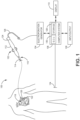
- FIG. 1 is a diagrammatic and block diagram view of a system 100 for providing electroporation therapy according to some embodiments.
- the system 100 includes a catheter 102, electroporation generator 104, computer system 106, input/output 108, and display 110.
- the catheter 102 includes a handle 112 and a shaft 114 having a distal end 116 and a proximal end 118.
- a conformable electrode assembly 120 is located at the distal end 116 of the shaft 114 and is configured to deliver electroporation therapy to adjacent tissue 122.
- FIG. 1 is a diagrammatic and block diagram view of a system 100 for providing electroporation therapy according to some embodiments.
- the system 100 includes a catheter 102, electroporation generator 104, computer system 106, input/output 108, and display 110.
- the catheter 102 includes a handle 112 and a shaft 114 having a distal end 116 and a proximal end 118.
- a conformable electrode assembly 120
- computer system 106 includes storage 128 capable of storing computer readable instructions and an electronic control unit (ECU 130) capable of executing computer readable instructions.
- computer system 106 communicates bi-directionally with input/output 108 and further displays information via display 110.
- computer system 106 controls generation and delivery of electroporation pulses by electroporation generator 104. This may include modifying one or more of the amplitude (i.e., intensity), duration, and number of pulses delivered by the electroporation generator 104.
- computer system 106 may utilize the one or more sensed signals - whether electric, magnetic, or optical - as inputs to enable one or more functions including visualization, navigation, and/or mapping.
- the one or more sensed signals may be utilized to visualize the location of the catheter within the patient's body as well as to aid in navigating the catheter through the patient's vasculature to the desired location within the patient's body.
- electrical signals e.g., electrocardiogram signals
- electrodes located on the electrode assembly 120 may be utilized to map the propagation of electrical signals within the patient's heart or to verify that disruptive signals have been blocked following delivery of electroporation pulses.
- one or more sensed signals are utilized to verify the position of the electrode assembly 120 relative to the tissue to be electroporated.
- one or more sensed signals are utilized to verify that the first side of a conformable electrode assembly comprising at least the first electrode and the non-conductive material surrounding the first electrode is in contact with the tissue. Physical contact between the first side of the non-conformable electrode assembly and the tissue selected to receive electroporation therapy ensures that the conductive path formed between the first electrode and the second electrode includes the tissue adjacent to the first electrode.
- the electrode assembly 220 is connected to the shaft 214 via a hinge 258 that allows the orientation of the primary plane defined by the electrode assembly 220 to be modified or deflected relative to the shaft 214.
- the deflection of the electrode assembly 220 is controlled by the operator via the handle 112 (shown in FIG. 1 ).
- the deflection of the electrode assembly 220 is in response to force applied to the electrode assembly 220 when brought into contact with adjacent tissue. In this way, the hinge 218 aids in allowing the first side 244 to be brought into contact with the tissue 250 to be treated.
- first non-conductive portion 360 and/or second non-conductive portion 362 may be flexible and/or compressible, in which case it may be desirable for the first and second electrodes 346 and 354 to be recessed from the top of the respective non-conductive portions 360 and 362, respectively.
- first electrode 346 and/or the second electrode 354 may protrude from the top surface of the respective non-conductive portions 360 and 362, respectively.
- the first and second non-conductive portions 360 and 362 may be conformed (i.e., rolled up) to fit within the lumen of the shaft. When unsheathed from the shaft the first and second conductive portions 360 and 362, respectively, return to a desired shape - for example a planar geometry as shown in FIGS. 3a-3d .
- the desired shape i.e. in the absence of external force
- the purpose of the non-conductive portion 548 surrounding the first central electrode 546 is to ensure that the conductive path formed between the first central electrode 546 and a second electrode (for example, located on the second side 552) during electroporation therapy includes the tissue located adjacent to the first central electrode 546. That is, the non-conductive portion 548 forces the conductive path to include the adjacent tissue as desired.
- non-conductive portion 548 is also recessed to receive and retain the flexible circuit board 582, the plurality of electrodes 584, as well as the first central electrode 546.
- the non-conductive portion 508 is recessed such that the plurality of electrodes 584 and first central electrode 546 are relatively planar with the non-conductive portion 548.
- the plurality of electrodes 584 may be recessed such that the non-conductive portion 584 is proud of or protrudes relative to the plurality of electrodes 584 (as discussed above with respect to the first central electrode 546).
- the circuit board 582 is a flexible circuit that allows the circuit board 582 to bend with the flexible non-conductive portion 548.
- the circuit board 582 comprises a shape memory material.
- the conformable electrode assembly 520 is comprised of flexible materials that allow the conformable electrode assembly 520 to be rolled up to fit within the lumen of the shaft 514 during navigation of the catheter to the desired location within the patient's body.
- the shape memory material utilized for the circuit board 582 acts to return the conformable electrode assembly 520 to a desired shape. For example, in the embodiment shown in FIG.
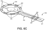
- a circuit board 682 that includes a plurality of electrodes 684 located on an outer periphery of the circuit board 682 in addition to a first central electrode 646.
- the circuit board 682 would be affixed to the non-conductive portion of the electrode assembly (for example, to non-conductive portion 548 as shown in FIG. 5 ).
- the non-conductive portion 648 is around (i.e., surrounding) at least a portion of the circuit board 682, and includes a number of recesses or openings that expose the one or more electrodes associated with the circuit board 682.
- FIG. 6c a circuit board 682 is shown that includes a plurality of electrodes 684 located on an outer periphery of the circuit board 682 in addition to a first central electrode 646.
- the circuit board 682 would be affixed to the non-conductive portion of the electrode assembly (for example, to non-conductive portion 548 as shown in FIG. 5 ).
- the non-conductive portion 648 is around (i.e., surrounding)
- non-conductive portion 648 includes a central recess 645 that exposes a first central electrode 646 and a plurality of peripheral recesses 685 that each expose one of the plurality of peripheral electrodes 684.
- the first central electrode 646 and the plurality of peripheral electrodes 684 are recessed relative the planar surface of the non-conductive portion 648.
- one or both of the first central electrode 646 and the plurality of peripheral electrodes 684 - together with the non-conductive portion 648 - form an approximately planar surface for contact with tissue.
- the components and geometry provided on the first side 644 of the electrode assembly 620 are mirrored on the second side 652 of the electrode assembly 620.
- the second side 652 may include no electrodes (and therefore, no recesses in the non-conductive portion 648) or may include only a subset of the electrodes and recesses included on the first side 644.
- circuit board 682 may be also be multi-layered (not shown in FIG. 6c ).
- circuit board 682 includes a top side and a bottom side, with at least some of the conductive traces formed between the contact pads 686 and electrodes 684 located on the top side and some of the conductive traces formed on the bottom side.
- a subset of conductive traces are shown extending along a top side of the circuit board 682.
- FIGS. 7a and 7b a side view and top view of the shaft 714 and electrode assembly 720 are shown, respectively, according to some embodiments.
- the electrode assembly 720 is oriented such that the first side 744 and second side 752 of the electrode assembly are not visible.
- FIG. 7b a top view of the shaft 714 and electrode assembly 720 are shown in which a first central electrode 746 and additional electrodes 784 located around the periphery of the electrode assembly 720 are visible.
- one or more physiological signals are measured using one or more electrodes located on a first side of the conformable electrode assembly.
- the conformable electrode assembly includes a plurality of electrodes located around a periphery of the first side, each of which may be utilized to sense one or more electrical signals.
- sensed signals may include electrical signals sensed within the myocardial tissue.
- sensed signals may include an impedance signal measured between two or more electrodes.
- one or more signals or combination of signals may be measured.
- the first central electrode utilized for delivering electroporation therapy may also be utilized to measure one or more physiological signals.
- the determination is made based on signals detected using one or more of the plurality of electrodes (if present) located around the periphery of the first side (as shown in FIGS. 5 and 6 , for example).
- sufficient contact with tissue is detected if a threshold number of electrodes detect a signal indicative of tissue contact. For example, in some embodiments if six out of the eight electrodes located around the periphery of the first side detect contact with the adjacent tissue, then sufficient contact with tissue is detected.
- other thresholds may be utilized based on the available sensors to determine whether the first side is in contact with the adjacent tissue.
Landscapes
- Health & Medical Sciences (AREA)
- Life Sciences & Earth Sciences (AREA)
- Engineering & Computer Science (AREA)
- Veterinary Medicine (AREA)
- Public Health (AREA)
- Nuclear Medicine, Radiotherapy & Molecular Imaging (AREA)
- Biomedical Technology (AREA)
- Animal Behavior & Ethology (AREA)
- General Health & Medical Sciences (AREA)
- Heart & Thoracic Surgery (AREA)
- Surgery (AREA)
- Cardiology (AREA)
- Radiology & Medical Imaging (AREA)
- Biophysics (AREA)
- Physics & Mathematics (AREA)
- Plasma & Fusion (AREA)
- Otolaryngology (AREA)
- Medical Informatics (AREA)
- Molecular Biology (AREA)
- Vascular Medicine (AREA)
- Measurement And Recording Of Electrical Phenomena And Electrical Characteristics Of The Living Body (AREA)
- Surgical Instruments (AREA)
Claims (15)
- Elektroporationsvorrichtung mit:einem Schaft (214; 514), der ein proximales Ende und ein distales Ende (216) aufweist; undeine anpassbaren Elektrodenanordnung (20; 320; 520; 620), die sich an dem distalen Ende des Schafts (214; 514) befindet, wobei die Elektrodenanordnung eine erste Seite (244; 344; 544) und eine zweite Seite (252; 552) aufweist, wobei die erste Seite (244; 344; 544) einen ersten nicht leitfähigen Bereich (248; 360; 548; 648) und eine erste Elektrode (246; 346; 546; 646), die relativ zu dem nicht leitfähigen Bereich (248; 360; 548; 648) zentral auf der ersten Seite (244; 344; 544) vorgesehen ist, aufweist, wobei der erste nicht leitfähige Bereich (248; 360; 548; 648) durch einen ersten Flächenbereich definiert ist, und die erste Elektrode (246; 346; 546; 646) durch einen zweiten Flächenbereich definiert ist, wobei der erste Flächenbereich größer als der zweite Flächenbereich ist.
- Elektroporationsvorrichtung nach Anspruch 1, bei der die erste Elektrode (246; 346; 546; 646) und der erste nicht leitfähige Bereich (248; 360; 548; 648) eine relativ planare Fläche zur Kontaktierung mit dem Gewebe bilden, oder wobeidie erste Elektrode (246; 346; 546; 646) innerhalb des ersten nicht leitfähigen Bereichs (248; 360; 548; 648) vertieft ausgebildet ist, wobei der erste nicht leitfähige Bereich (248; 360; 548; 648) zu der ersten Elektrode (246; 346; 546; 646) überstehend positioniert ist, oder wobeidie erste Elektrode (246; 346; 546; 646) innerhalb einer Vertiefung in dem ersten nicht leitfähigen Bereich (248; 360; 548; 648) befestigt ist, wobei die erste Elektrode (246; 346; 546; 646) zu dem ersten nicht leitfähigen Bereich (248; 360; 548; 648) überstehend positioniert ist.
- Elektroporationsvorrichtung nach Anspruch 1 oder 2, bei der der erste nicht leitfähige Bereich (248; 360; 548; 648) flexibel ist.
- Elektroporationsvorrichtung nach einem der Ansprüche 1 bis 3, ferner mit:
einer zweiten Elektrode (354), wobei die erste Elektrode (246; 346; 546; 646) und die zweite Elektrode (354) konfiguriert sind zur Lieferung einer Elektroporationstherapie an Gewebe, das sich benachbart zu der ersten Seite (244; 344; 544) der Elektrodenanordnung (220; 320; 520; 620) befindet. - Elektroporationsvorrichtung nach Anspruch 4, bei der die zweite Elektrode (354) auf der zweiten Seite (252; 552) der anpassbaren Elektrodenanordnung (220; 320; 520; 620) der ersten Seite (244; 344; 544) gegenüberliegend vorgesehen ist.
- Elektroporationsvorrichtung nach Anspruch 5, bei der die zweite Seite (252; 552) einen zweiten nicht leitfähigen Bereich (362) aufweist, wobei die zweite Elektrode (354) an dem zweiten nicht leitfähigen Bereich (362) befestigt und zentral auf der zweiten Seite (252; 552) vorgesehen ist, wobei der zweite nicht leitfähige Bereich (362) durch einen dritten Flächenbereich definiert ist, und die zweite Elektrode (354) durch einen vierten Flächenbereich definiert ist, wobei der dritte Flächenbereich größer als der vierte Flächenbereich ist.
- Elektroporationsvorrichtung nach Anspruch 4, bei der die zweite Elektrode eine Ringelektrode (240, 242; 540, 542) ist, die sich auf dem Schaft befindet.
- Elektroporationsvorrichtung nach einem der Ansprüche 1 bis 7, ferner mit:
einer Leiterplatte (682), wobei die erste Elektrode (646) an der Leiterplatte (682) befestigt ist, und der nicht leitfähige Bereich (648) die Leiterplatte umgibt. - Elektroporationsvorrichtung nach Anspruch 8, bei der der nicht leitfähige Bereich (648) eine Öffnung aufweist, die zu der ersten Elektrode (646) ausgerichtet ist, wobei die erste Elektrode (646) relativ zu dem nicht leitfähigen Bereich (648) vertieft ausgebildet ist.
- Elektroporationsvorrichtung nach Anspruch 8 oder 9, bei der die Leiterplatte (682) eine flexible Leiterplatte (682) ist, die eine Formgedächtnisschicht aufweist, wobei die Formgedächtnisschicht eine voreingestellte Geometrie hat.
- Elektroporationsvorrichtung nach Anspruch 10, bei der die voreingestellte Geometrie konvex, konkav oder planar ist.
- Elektroporationsvorrichtung nach einem der Ansprüche 1 bis 10, ferner mit einer ersten Mehrzahl von Peripherieelektroden (584; 684), die sich auf einer Peripherie der ersten Seite (544) der anpassbaren Elektrodenanordnung (520; 620) befinden.
- Elektroporationstherapiesystem mit:einem Katheter (102), der aufweist:einen Griff (112);eine anpassbare Elektrodenanordnung nach einem der Ansprüche 1 bis 12, wobei die erste Seite (244; 344; 544) den ersten nicht leitfähigen Bereich (248; 360; 548; 648) und die erste Elektrode (246; 346; 546; 646), die an dem ersten nicht leitfähigen Bereich (248; 360; 548; 648) befestigt ist, aufweist, wobei die erste Elektrode (246; 346; 546; 646) zentral vorgesehen ist, und der nicht leitfähige Bereich (248; 360; 548; 648) die erste Elektrode (246; 346; 546; 646) in einer Ebene umgibt, die durch die erste Seite definiert ist; undder Schaft (214; 514) mit dem Griff (112) an dem proximalen Ende und mit der Elektrodenanordnung (220; 320; 520; 620) an dem distalen Ende (216) gekoppelt ist; undeinem Elektroporationsgenerator (104), der mit dem Katheter (102) gekoppelt ist zur Lieferung von Elektroporationsimpulsen an die erste Elektrode (246; 346; 546; 646).
- Elektroporationstherapiesystem nach Anspruch 13, bei dem, wenn von einem der Ansprüche 1 bis 7 abhängig, die anpassbare Elektrodenanordnung (520; 620) ferner eine erste Mehrzahl von Peripherieelektroden (584; 684) aufweist, die auf einer Peripherie der ersten Seite (544) der anpassbaren Elektrodenanordnung (520; 620) vorgesehen sind.
- Elektroporationstherapiesystem nach Anspruch 13, bei dem, wenn von einem der Ansprüche 1 bis 7 abhängig, die erste Elektrode (546; 646) und die erste Mehrzahl von Elektroden (584; 684) auf einem flexiblen Formgedächtnissubstrat vorgesehen sind, das eine voreingestellte Geometrie hat, wobei die anpassbare Elektrodenvorrichtung (520; 620) konfiguriert ist, um in ein Lumen des Schafts zu passen.
Applications Claiming Priority (2)
| Application Number | Priority Date | Filing Date | Title |
|---|---|---|---|
| US202063040751P | 2020-06-18 | 2020-06-18 | |
| PCT/US2021/036984 WO2021257397A1 (en) | 2020-06-18 | 2021-06-11 | Device and method for delivering electroporation therapy |
Publications (2)
| Publication Number | Publication Date |
|---|---|
| EP4125664A1 EP4125664A1 (de) | 2023-02-08 |
| EP4125664B1 true EP4125664B1 (de) | 2023-11-29 |
Family
ID=76744985
Family Applications (1)
| Application Number | Title | Priority Date | Filing Date |
|---|---|---|---|
| EP21737305.9A Active EP4125664B1 (de) | 2020-06-18 | 2021-06-11 | Vorrichtung zur verabreichung einer elektroporationstherapie |
Country Status (5)
| Country | Link |
|---|---|
| US (1) | US20230201581A1 (de) |
| EP (1) | EP4125664B1 (de) |
| JP (2) | JP7625016B2 (de) |
| CN (1) | CN115697227A (de) |
| WO (1) | WO2021257397A1 (de) |
Families Citing this family (2)
| Publication number | Priority date | Publication date | Assignee | Title |
|---|---|---|---|---|
| US12076071B2 (en) | 2020-08-14 | 2024-09-03 | Kardium Inc. | Systems and methods for treating tissue with pulsed field ablation |
| CN115568938A (zh) * | 2022-09-28 | 2023-01-06 | 上海交通大学 | 一种分形结构微电极及其制备方法和导管 |
Family Cites Families (23)
| Publication number | Priority date | Publication date | Assignee | Title |
|---|---|---|---|---|
| US5697882A (en) * | 1992-01-07 | 1997-12-16 | Arthrocare Corporation | System and method for electrosurgical cutting and ablation |
| ATE222732T1 (de) * | 1993-05-10 | 2002-09-15 | Arthrocare Corp | Vorrichtung zum chirurgischen schneiden |
| NL1001890C2 (nl) * | 1995-12-13 | 1997-06-17 | Cordis Europ | Catheter met plaatvormige elektrode-reeks. |
| US6152882A (en) * | 1999-01-26 | 2000-11-28 | Impulse Dynamics N.V. | Apparatus and method for chronic measurement of monophasic action potentials |
| JP3735641B2 (ja) | 1999-07-28 | 2006-01-18 | ネッパジーン株式会社 | 遺伝子導入方法及び薬剤導入方法 |
| EP1417352A4 (de) | 2001-06-11 | 2006-11-08 | Genorx Inc | Elektronischer nachweis biologischer moleküle mittels dünnschichten |
| CN2917571Y (zh) * | 2006-04-27 | 2007-07-04 | 迈德医疗科技(上海)有限公司 | 平面电极装置 |
| KR101642523B1 (ko) * | 2008-01-17 | 2016-07-25 | 제네트로닉스, 인코포레이티드 | 가변성 전류 밀도 단일 바늘 전기 천공 시스템 |
| US8882761B2 (en) | 2008-07-15 | 2014-11-11 | Catheffects, Inc. | Catheter and method for improved ablation |
| US8388615B2 (en) * | 2008-10-28 | 2013-03-05 | Smith & Nephew, Inc. | Electrosurgical device with controllable electric field profile |
| US8361066B2 (en) | 2009-01-12 | 2013-01-29 | Ethicon Endo-Surgery, Inc. | Electrical ablation devices |
| US20110160514A1 (en) * | 2009-12-31 | 2011-06-30 | Ethicon Endo-Surgery, Inc. | Electrical ablation devices |
| GB2477353B (en) | 2010-02-01 | 2015-12-02 | Gyrus Medical Ltd | Electrosurgical instrument |
| EP2732784A1 (de) * | 2012-11-20 | 2014-05-21 | Biotronik AG | Hochfrequenz-Applikationsvorrichtung zum vaskulären Einsatz, insbesondere zur Applikation von Hochfrequenz-Energie an der Renal-Arterienwand |
| CN105979896A (zh) | 2014-02-11 | 2016-09-28 | 圣犹达医疗用品心脏病学部门有限公司 | 消融导管和相关联的方法 |
| EP3282991A1 (de) * | 2015-04-17 | 2018-02-21 | Boston Scientific Scimed Inc. | Gewebediagnose und -behandlung mithilfe von elektroden und mini-elektroden |
| CN107635496B (zh) | 2015-05-12 | 2021-08-17 | 圣犹达医疗用品电生理部门有限公司 | 用于交流心脏不可逆电穿孔的非对称平衡波形 |
| WO2018201037A1 (en) | 2017-04-28 | 2018-11-01 | Farapulse, Inc. | Systems, devices, and methods for delivery of pulsed electric field ablative energy to endocardial tissue |
| WO2018071490A1 (en) | 2016-10-11 | 2018-04-19 | Acutus Medical, Inc. | Ablation system with force control |
| US11864825B2 (en) | 2018-05-02 | 2024-01-09 | Biosense Webster (Israel) Ltd. | Ablation catheter with selective radial energy delivery |
| KR102233949B1 (ko) * | 2018-11-16 | 2021-03-31 | 주식회사 루트로닉 | 질관 치료장치용 에너지 전달 모듈, 이를 포함하는 질관 치료장치의 제어방법 |
| IT201900005268A1 (it) * | 2019-04-05 | 2020-10-05 | Wise S R L | Dispositivo per elettroterapia e/o elettrofisiologia, kit e assieme |
| US12426945B2 (en) * | 2019-09-18 | 2025-09-30 | Biosense Webster (Israel) Ltd. | Catheter with thin-film electrodes on expandable mechanical structure |
-
2021
- 2021-06-11 EP EP21737305.9A patent/EP4125664B1/de active Active
- 2021-06-11 US US18/010,553 patent/US20230201581A1/en active Pending
- 2021-06-11 CN CN202180042127.8A patent/CN115697227A/zh active Pending
- 2021-06-11 JP JP2022577767A patent/JP7625016B2/ja active Active
- 2021-06-11 WO PCT/US2021/036984 patent/WO2021257397A1/en not_active Ceased
-
2025
- 2025-01-21 JP JP2025008540A patent/JP7843877B2/ja active Active
Also Published As
| Publication number | Publication date |
|---|---|
| JP7625016B2 (ja) | 2025-01-31 |
| US20230201581A1 (en) | 2023-06-29 |
| CN115697227A (zh) | 2023-02-03 |
| EP4125664A1 (de) | 2023-02-08 |
| JP2025072407A (ja) | 2025-05-09 |
| WO2021257397A1 (en) | 2021-12-23 |
| JP2023531437A (ja) | 2023-07-24 |
| JP7843877B2 (ja) | 2026-04-10 |
Similar Documents
| Publication | Publication Date | Title |
|---|---|---|
| US20250339201A1 (en) | Radio-Frequency Ablation and Direct Current Electroporation Catheters | |
| EP1343426B1 (de) | Mikroelekroden katheter zur ablation und einteilung | |
| US5385146A (en) | Orthogonal sensing for use in clinical electrophysiology | |
| US20170143416A1 (en) | Force sensing catheter with a slotted tube element | |
| EP3389530B1 (de) | Positionssensor mit mikroinduktion | |
| JP7843877B2 (ja) | エレクトロポレーション治療を送達するためのデバイスおよび方法 | |
| US20040082860A1 (en) | Microelectrode catheter for mapping and ablation | |
| US20040092806A1 (en) | Microelectrode catheter for mapping and ablation | |
| US20240197393A1 (en) | Catheter shape detection for map and ablate catheters | |
| IL309726A (en) | Position and Force Sensors for Catheters | |
| EP3629894B1 (de) | Katheter und federelement zur kontaktkrafterfassung | |
| EP3363355B1 (de) | Elektrophysiologische vorrichtung und verfahren zur konstruktion der elektrophysiologischen vorrichtung | |
| US20170290617A1 (en) | Force sensing catheter with a magnet and an inductive sensor | |
| US20240173071A1 (en) | Flexible Distal-End Assembly with Double-Sided Electrode Array and Irrigation | |
| EP4541303A1 (de) | Flexible schaltungselektroden für lasso-katheter | |
| EP4385441B1 (de) | Katheterendeffektor mit gewebter flexschaltung | |
| CN118266938A (zh) | 具有交错衬底的多电极导管 |
Legal Events
| Date | Code | Title | Description |
|---|---|---|---|
| STAA | Information on the status of an ep patent application or granted ep patent |
Free format text: STATUS: UNKNOWN |
|
| STAA | Information on the status of an ep patent application or granted ep patent |
Free format text: STATUS: THE INTERNATIONAL PUBLICATION HAS BEEN MADE |
|
| PUAI | Public reference made under article 153(3) epc to a published international application that has entered the european phase |
Free format text: ORIGINAL CODE: 0009012 |
|
| STAA | Information on the status of an ep patent application or granted ep patent |
Free format text: STATUS: REQUEST FOR EXAMINATION WAS MADE |
|
| 17P | Request for examination filed |
Effective date: 20221024 |
|
| AK | Designated contracting states |
Kind code of ref document: A1 Designated state(s): AL AT BE BG CH CY CZ DE DK EE ES FI FR GB GR HR HU IE IS IT LI LT LU LV MC MK MT NL NO PL PT RO RS SE SI SK SM TR |
|
| GRAP | Despatch of communication of intention to grant a patent |
Free format text: ORIGINAL CODE: EPIDOSNIGR1 |
|
| STAA | Information on the status of an ep patent application or granted ep patent |
Free format text: STATUS: GRANT OF PATENT IS INTENDED |
|
| P01 | Opt-out of the competence of the unified patent court (upc) registered |
Effective date: 20230616 |
|
| DAV | Request for validation of the european patent (deleted) | ||
| DAX | Request for extension of the european patent (deleted) | ||
| INTG | Intention to grant announced |
Effective date: 20230721 |
|
| GRAS | Grant fee paid |
Free format text: ORIGINAL CODE: EPIDOSNIGR3 |
|
| GRAA | (expected) grant |
Free format text: ORIGINAL CODE: 0009210 |
|
| STAA | Information on the status of an ep patent application or granted ep patent |
Free format text: STATUS: THE PATENT HAS BEEN GRANTED |
|
| AK | Designated contracting states |
Kind code of ref document: B1 Designated state(s): AL AT BE BG CH CY CZ DE DK EE ES FI FR GB GR HR HU IE IS IT LI LT LU LV MC MK MT NL NO PL PT RO RS SE SI SK SM TR |
|
| REG | Reference to a national code |
Ref country code: GB Ref legal event code: FG4D |
|
| REG | Reference to a national code |
Ref country code: CH Ref legal event code: EP |
|
| REG | Reference to a national code |
Ref country code: DE Ref legal event code: R096 Ref document number: 602021007338 Country of ref document: DE |
|
| REG | Reference to a national code |
Ref country code: IE Ref legal event code: FG4D |
|
| REG | Reference to a national code |
Ref country code: LT Ref legal event code: MG9D |
|
| REG | Reference to a national code |
Ref country code: NL Ref legal event code: MP Effective date: 20231129 |
|
| PG25 | Lapsed in a contracting state [announced via postgrant information from national office to epo] |
Ref country code: GR Free format text: LAPSE BECAUSE OF FAILURE TO SUBMIT A TRANSLATION OF THE DESCRIPTION OR TO PAY THE FEE WITHIN THE PRESCRIBED TIME-LIMIT Effective date: 20240301 |
|
| PG25 | Lapsed in a contracting state [announced via postgrant information from national office to epo] |
Ref country code: IS Free format text: LAPSE BECAUSE OF FAILURE TO SUBMIT A TRANSLATION OF THE DESCRIPTION OR TO PAY THE FEE WITHIN THE PRESCRIBED TIME-LIMIT Effective date: 20240329 |
|
| PG25 | Lapsed in a contracting state [announced via postgrant information from national office to epo] |
Ref country code: LT Free format text: LAPSE BECAUSE OF FAILURE TO SUBMIT A TRANSLATION OF THE DESCRIPTION OR TO PAY THE FEE WITHIN THE PRESCRIBED TIME-LIMIT Effective date: 20231129 |
|
| PG25 | Lapsed in a contracting state [announced via postgrant information from national office to epo] |
Ref country code: ES Free format text: LAPSE BECAUSE OF FAILURE TO SUBMIT A TRANSLATION OF THE DESCRIPTION OR TO PAY THE FEE WITHIN THE PRESCRIBED TIME-LIMIT Effective date: 20231129 |
|
| PG25 | Lapsed in a contracting state [announced via postgrant information from national office to epo] |
Ref country code: LT Free format text: LAPSE BECAUSE OF FAILURE TO SUBMIT A TRANSLATION OF THE DESCRIPTION OR TO PAY THE FEE WITHIN THE PRESCRIBED TIME-LIMIT Effective date: 20231129 Ref country code: IS Free format text: LAPSE BECAUSE OF FAILURE TO SUBMIT A TRANSLATION OF THE DESCRIPTION OR TO PAY THE FEE WITHIN THE PRESCRIBED TIME-LIMIT Effective date: 20240329 Ref country code: GR Free format text: LAPSE BECAUSE OF FAILURE TO SUBMIT A TRANSLATION OF THE DESCRIPTION OR TO PAY THE FEE WITHIN THE PRESCRIBED TIME-LIMIT Effective date: 20240301 Ref country code: ES Free format text: LAPSE BECAUSE OF FAILURE TO SUBMIT A TRANSLATION OF THE DESCRIPTION OR TO PAY THE FEE WITHIN THE PRESCRIBED TIME-LIMIT Effective date: 20231129 Ref country code: BG Free format text: LAPSE BECAUSE OF FAILURE TO SUBMIT A TRANSLATION OF THE DESCRIPTION OR TO PAY THE FEE WITHIN THE PRESCRIBED TIME-LIMIT Effective date: 20240229 |
|
| REG | Reference to a national code |
Ref country code: AT Ref legal event code: MK05 Ref document number: 1635305 Country of ref document: AT Kind code of ref document: T Effective date: 20231129 |
|
| PG25 | Lapsed in a contracting state [announced via postgrant information from national office to epo] |
Ref country code: NL Free format text: LAPSE BECAUSE OF FAILURE TO SUBMIT A TRANSLATION OF THE DESCRIPTION OR TO PAY THE FEE WITHIN THE PRESCRIBED TIME-LIMIT Effective date: 20231129 |
|
| PG25 | Lapsed in a contracting state [announced via postgrant information from national office to epo] |
Ref country code: SE Free format text: LAPSE BECAUSE OF FAILURE TO SUBMIT A TRANSLATION OF THE DESCRIPTION OR TO PAY THE FEE WITHIN THE PRESCRIBED TIME-LIMIT Effective date: 20231129 Ref country code: RS Free format text: LAPSE BECAUSE OF FAILURE TO SUBMIT A TRANSLATION OF THE DESCRIPTION OR TO PAY THE FEE WITHIN THE PRESCRIBED TIME-LIMIT Effective date: 20231129 Ref country code: PL Free format text: LAPSE BECAUSE OF FAILURE TO SUBMIT A TRANSLATION OF THE DESCRIPTION OR TO PAY THE FEE WITHIN THE PRESCRIBED TIME-LIMIT Effective date: 20231129 Ref country code: NO Free format text: LAPSE BECAUSE OF FAILURE TO SUBMIT A TRANSLATION OF THE DESCRIPTION OR TO PAY THE FEE WITHIN THE PRESCRIBED TIME-LIMIT Effective date: 20240229 Ref country code: NL Free format text: LAPSE BECAUSE OF FAILURE TO SUBMIT A TRANSLATION OF THE DESCRIPTION OR TO PAY THE FEE WITHIN THE PRESCRIBED TIME-LIMIT Effective date: 20231129 Ref country code: LV Free format text: LAPSE BECAUSE OF FAILURE TO SUBMIT A TRANSLATION OF THE DESCRIPTION OR TO PAY THE FEE WITHIN THE PRESCRIBED TIME-LIMIT Effective date: 20231129 Ref country code: HR Free format text: LAPSE BECAUSE OF FAILURE TO SUBMIT A TRANSLATION OF THE DESCRIPTION OR TO PAY THE FEE WITHIN THE PRESCRIBED TIME-LIMIT Effective date: 20231129 |
|
| PG25 | Lapsed in a contracting state [announced via postgrant information from national office to epo] |
Ref country code: DK Free format text: LAPSE BECAUSE OF FAILURE TO SUBMIT A TRANSLATION OF THE DESCRIPTION OR TO PAY THE FEE WITHIN THE PRESCRIBED TIME-LIMIT Effective date: 20231129 |
|
| PG25 | Lapsed in a contracting state [announced via postgrant information from national office to epo] |
Ref country code: CZ Free format text: LAPSE BECAUSE OF FAILURE TO SUBMIT A TRANSLATION OF THE DESCRIPTION OR TO PAY THE FEE WITHIN THE PRESCRIBED TIME-LIMIT Effective date: 20231129 Ref country code: AT Free format text: LAPSE BECAUSE OF FAILURE TO SUBMIT A TRANSLATION OF THE DESCRIPTION OR TO PAY THE FEE WITHIN THE PRESCRIBED TIME-LIMIT Effective date: 20231129 |
|
| PG25 | Lapsed in a contracting state [announced via postgrant information from national office to epo] |
Ref country code: SK Free format text: LAPSE BECAUSE OF FAILURE TO SUBMIT A TRANSLATION OF THE DESCRIPTION OR TO PAY THE FEE WITHIN THE PRESCRIBED TIME-LIMIT Effective date: 20231129 |
|
| PG25 | Lapsed in a contracting state [announced via postgrant information from national office to epo] |
Ref country code: SM Free format text: LAPSE BECAUSE OF FAILURE TO SUBMIT A TRANSLATION OF THE DESCRIPTION OR TO PAY THE FEE WITHIN THE PRESCRIBED TIME-LIMIT Effective date: 20231129 Ref country code: SK Free format text: LAPSE BECAUSE OF FAILURE TO SUBMIT A TRANSLATION OF THE DESCRIPTION OR TO PAY THE FEE WITHIN THE PRESCRIBED TIME-LIMIT Effective date: 20231129 Ref country code: RO Free format text: LAPSE BECAUSE OF FAILURE TO SUBMIT A TRANSLATION OF THE DESCRIPTION OR TO PAY THE FEE WITHIN THE PRESCRIBED TIME-LIMIT Effective date: 20231129 Ref country code: EE Free format text: LAPSE BECAUSE OF FAILURE TO SUBMIT A TRANSLATION OF THE DESCRIPTION OR TO PAY THE FEE WITHIN THE PRESCRIBED TIME-LIMIT Effective date: 20231129 Ref country code: DK Free format text: LAPSE BECAUSE OF FAILURE TO SUBMIT A TRANSLATION OF THE DESCRIPTION OR TO PAY THE FEE WITHIN THE PRESCRIBED TIME-LIMIT Effective date: 20231129 Ref country code: CZ Free format text: LAPSE BECAUSE OF FAILURE TO SUBMIT A TRANSLATION OF THE DESCRIPTION OR TO PAY THE FEE WITHIN THE PRESCRIBED TIME-LIMIT Effective date: 20231129 Ref country code: AT Free format text: LAPSE BECAUSE OF FAILURE TO SUBMIT A TRANSLATION OF THE DESCRIPTION OR TO PAY THE FEE WITHIN THE PRESCRIBED TIME-LIMIT Effective date: 20231129 |
|
| PG25 | Lapsed in a contracting state [announced via postgrant information from national office to epo] |
Ref country code: PT Free format text: LAPSE BECAUSE OF FAILURE TO SUBMIT A TRANSLATION OF THE DESCRIPTION OR TO PAY THE FEE WITHIN THE PRESCRIBED TIME-LIMIT Effective date: 20240401 |
|
| PG25 | Lapsed in a contracting state [announced via postgrant information from national office to epo] |
Ref country code: PT Free format text: LAPSE BECAUSE OF FAILURE TO SUBMIT A TRANSLATION OF THE DESCRIPTION OR TO PAY THE FEE WITHIN THE PRESCRIBED TIME-LIMIT Effective date: 20240401 |
|
| REG | Reference to a national code |
Ref country code: DE Ref legal event code: R097 Ref document number: 602021007338 Country of ref document: DE |
|
| PLBE | No opposition filed within time limit |
Free format text: ORIGINAL CODE: 0009261 |
|
| STAA | Information on the status of an ep patent application or granted ep patent |
Free format text: STATUS: NO OPPOSITION FILED WITHIN TIME LIMIT |
|
| PG25 | Lapsed in a contracting state [announced via postgrant information from national office to epo] |
Ref country code: SI Free format text: LAPSE BECAUSE OF FAILURE TO SUBMIT A TRANSLATION OF THE DESCRIPTION OR TO PAY THE FEE WITHIN THE PRESCRIBED TIME-LIMIT Effective date: 20231129 |
|
| PG25 | Lapsed in a contracting state [announced via postgrant information from national office to epo] |
Ref country code: SI Free format text: LAPSE BECAUSE OF FAILURE TO SUBMIT A TRANSLATION OF THE DESCRIPTION OR TO PAY THE FEE WITHIN THE PRESCRIBED TIME-LIMIT Effective date: 20231129 |
|
| 26N | No opposition filed |
Effective date: 20240830 |
|
| PG25 | Lapsed in a contracting state [announced via postgrant information from national office to epo] |
Ref country code: MC Free format text: LAPSE BECAUSE OF FAILURE TO SUBMIT A TRANSLATION OF THE DESCRIPTION OR TO PAY THE FEE WITHIN THE PRESCRIBED TIME-LIMIT Effective date: 20231129 |
|
| REG | Reference to a national code |
Ref country code: CH Ref legal event code: PL |
|
| PG25 | Lapsed in a contracting state [announced via postgrant information from national office to epo] |
Ref country code: LU Free format text: LAPSE BECAUSE OF NON-PAYMENT OF DUE FEES Effective date: 20240611 |
|
| PG25 | Lapsed in a contracting state [announced via postgrant information from national office to epo] |
Ref country code: IE Free format text: LAPSE BECAUSE OF NON-PAYMENT OF DUE FEES Effective date: 20240611 |
|
| PG25 | Lapsed in a contracting state [announced via postgrant information from national office to epo] |
Ref country code: BE Free format text: LAPSE BECAUSE OF NON-PAYMENT OF DUE FEES Effective date: 20240630 Ref country code: CH Free format text: LAPSE BECAUSE OF NON-PAYMENT OF DUE FEES Effective date: 20240630 |
|
| REG | Reference to a national code |
Ref country code: BE Ref legal event code: MM Effective date: 20240630 |
|
| PGFP | Annual fee paid to national office [announced via postgrant information from national office to epo] |
Ref country code: DE Payment date: 20250509 Year of fee payment: 5 |
|
| PGFP | Annual fee paid to national office [announced via postgrant information from national office to epo] |
Ref country code: GB Payment date: 20250508 Year of fee payment: 5 |
|
| PGFP | Annual fee paid to national office [announced via postgrant information from national office to epo] |
Ref country code: FR Payment date: 20250512 Year of fee payment: 5 |
|
| PG25 | Lapsed in a contracting state [announced via postgrant information from national office to epo] |
Ref country code: FI Free format text: LAPSE BECAUSE OF FAILURE TO SUBMIT A TRANSLATION OF THE DESCRIPTION OR TO PAY THE FEE WITHIN THE PRESCRIBED TIME-LIMIT Effective date: 20231129 |
|
| PGFP | Annual fee paid to national office [announced via postgrant information from national office to epo] |
Ref country code: IT Payment date: 20250610 Year of fee payment: 5 |
|
| PG25 | Lapsed in a contracting state [announced via postgrant information from national office to epo] |
Ref country code: CY Free format text: LAPSE BECAUSE OF FAILURE TO SUBMIT A TRANSLATION OF THE DESCRIPTION OR TO PAY THE FEE WITHIN THE PRESCRIBED TIME-LIMIT; INVALID AB INITIO Effective date: 20210611 |
|
| PG25 | Lapsed in a contracting state [announced via postgrant information from national office to epo] |
Ref country code: HU Free format text: LAPSE BECAUSE OF FAILURE TO SUBMIT A TRANSLATION OF THE DESCRIPTION OR TO PAY THE FEE WITHIN THE PRESCRIBED TIME-LIMIT; INVALID AB INITIO Effective date: 20210611 |