EP1343426B1 - Mikroelekroden katheter zur ablation und einteilung - Google Patents
Mikroelekroden katheter zur ablation und einteilung Download PDFInfo
- Publication number
- EP1343426B1 EP1343426B1 EP01990167A EP01990167A EP1343426B1 EP 1343426 B1 EP1343426 B1 EP 1343426B1 EP 01990167 A EP01990167 A EP 01990167A EP 01990167 A EP01990167 A EP 01990167A EP 1343426 B1 EP1343426 B1 EP 1343426B1
- Authority
- EP
- European Patent Office
- Prior art keywords
- catheter
- electrodes
- mapping
- electrode
- ablation
- Prior art date
- Legal status (The legal status is an assumption and is not a legal conclusion. Google has not performed a legal analysis and makes no representation as to the accuracy of the status listed.)
- Expired - Lifetime
Links
Images


Classifications
-
- A—HUMAN NECESSITIES
- A61—MEDICAL OR VETERINARY SCIENCE; HYGIENE
- A61B—DIAGNOSIS; SURGERY; IDENTIFICATION
- A61B18/00—Surgical instruments, devices or methods for transferring non-mechanical forms of energy to or from the body
- A61B18/04—Surgical instruments, devices or methods for transferring non-mechanical forms of energy to or from the body by heating
- A61B18/12—Surgical instruments, devices or methods for transferring non-mechanical forms of energy to or from the body by heating by passing a current through the tissue to be heated, e.g. high-frequency current
- A61B18/14—Probes or electrodes therefor
- A61B18/1492—Probes or electrodes therefor having a flexible, catheter-like structure, e.g. for heart ablation
-
- A—HUMAN NECESSITIES
- A61—MEDICAL OR VETERINARY SCIENCE; HYGIENE
- A61B—DIAGNOSIS; SURGERY; IDENTIFICATION
- A61B17/00—Surgical instruments, devices or methods, e.g. tourniquets
- A61B17/00234—Surgical instruments, devices or methods, e.g. tourniquets for minimally invasive surgery
- A61B2017/00292—Surgical instruments, devices or methods, e.g. tourniquets for minimally invasive surgery mounted on or guided by flexible, e.g. catheter-like, means
- A61B2017/003—Steerable
-
- A—HUMAN NECESSITIES
- A61—MEDICAL OR VETERINARY SCIENCE; HYGIENE
- A61B—DIAGNOSIS; SURGERY; IDENTIFICATION
- A61B18/00—Surgical instruments, devices or methods for transferring non-mechanical forms of energy to or from the body
- A61B2018/00005—Cooling or heating of the probe or tissue immediately surrounding the probe
- A61B2018/00011—Cooling or heating of the probe or tissue immediately surrounding the probe with fluids
- A61B2018/00029—Cooling or heating of the probe or tissue immediately surrounding the probe with fluids open
-
- A—HUMAN NECESSITIES
- A61—MEDICAL OR VETERINARY SCIENCE; HYGIENE
- A61B—DIAGNOSIS; SURGERY; IDENTIFICATION
- A61B18/00—Surgical instruments, devices or methods for transferring non-mechanical forms of energy to or from the body
- A61B2018/00315—Surgical instruments, devices or methods for transferring non-mechanical forms of energy to or from the body for treatment of particular body parts
- A61B2018/00345—Vascular system
- A61B2018/00351—Heart
-
- A—HUMAN NECESSITIES
- A61—MEDICAL OR VETERINARY SCIENCE; HYGIENE
- A61B—DIAGNOSIS; SURGERY; IDENTIFICATION
- A61B18/00—Surgical instruments, devices or methods for transferring non-mechanical forms of energy to or from the body
- A61B2018/00571—Surgical instruments, devices or methods for transferring non-mechanical forms of energy to or from the body for achieving a particular surgical effect
- A61B2018/00577—Ablation
-
- A—HUMAN NECESSITIES
- A61—MEDICAL OR VETERINARY SCIENCE; HYGIENE
- A61B—DIAGNOSIS; SURGERY; IDENTIFICATION
- A61B18/00—Surgical instruments, devices or methods for transferring non-mechanical forms of energy to or from the body
- A61B2018/00636—Sensing and controlling the application of energy
- A61B2018/00773—Sensed parameters
- A61B2018/00791—Temperature
- A61B2018/00797—Temperature measured by multiple temperature sensors
-
- A—HUMAN NECESSITIES
- A61—MEDICAL OR VETERINARY SCIENCE; HYGIENE
- A61B—DIAGNOSIS; SURGERY; IDENTIFICATION
- A61B18/00—Surgical instruments, devices or methods for transferring non-mechanical forms of energy to or from the body
- A61B2018/00636—Sensing and controlling the application of energy
- A61B2018/00773—Sensed parameters
- A61B2018/00791—Temperature
- A61B2018/00821—Temperature measured by a thermocouple
-
- A—HUMAN NECESSITIES
- A61—MEDICAL OR VETERINARY SCIENCE; HYGIENE
- A61B—DIAGNOSIS; SURGERY; IDENTIFICATION
- A61B18/00—Surgical instruments, devices or methods for transferring non-mechanical forms of energy to or from the body
- A61B2018/00636—Sensing and controlling the application of energy
- A61B2018/00773—Sensed parameters
- A61B2018/00839—Bioelectrical parameters, e.g. ECG, EEG
-
- A—HUMAN NECESSITIES
- A61—MEDICAL OR VETERINARY SCIENCE; HYGIENE
- A61B—DIAGNOSIS; SURGERY; IDENTIFICATION
- A61B18/00—Surgical instruments, devices or methods for transferring non-mechanical forms of energy to or from the body
- A61B2018/0091—Handpieces of the surgical instrument or device
- A61B2018/00916—Handpieces of the surgical instrument or device with means for switching or controlling the main function of the instrument or device
- A61B2018/0094—Types of switches or controllers
- A61B2018/00946—Types of switches or controllers slidable
-
- A—HUMAN NECESSITIES
- A61—MEDICAL OR VETERINARY SCIENCE; HYGIENE
- A61B—DIAGNOSIS; SURGERY; IDENTIFICATION
- A61B18/00—Surgical instruments, devices or methods for transferring non-mechanical forms of energy to or from the body
- A61B18/04—Surgical instruments, devices or methods for transferring non-mechanical forms of energy to or from the body by heating
- A61B18/12—Surgical instruments, devices or methods for transferring non-mechanical forms of energy to or from the body by heating by passing a current through the tissue to be heated, e.g. high-frequency current
- A61B18/14—Probes or electrodes therefor
- A61B2018/1467—Probes or electrodes therefor using more than two electrodes on a single probe
-
- A—HUMAN NECESSITIES
- A61—MEDICAL OR VETERINARY SCIENCE; HYGIENE
- A61B—DIAGNOSIS; SURGERY; IDENTIFICATION
- A61B18/00—Surgical instruments, devices or methods for transferring non-mechanical forms of energy to or from the body
- A61B18/04—Surgical instruments, devices or methods for transferring non-mechanical forms of energy to or from the body by heating
- A61B18/12—Surgical instruments, devices or methods for transferring non-mechanical forms of energy to or from the body by heating by passing a current through the tissue to be heated, e.g. high-frequency current
- A61B18/14—Probes or electrodes therefor
- A61B2018/1472—Probes or electrodes therefor for use with liquid electrolyte, e.g. virtual electrodes
-
- A—HUMAN NECESSITIES
- A61—MEDICAL OR VETERINARY SCIENCE; HYGIENE
- A61B—DIAGNOSIS; SURGERY; IDENTIFICATION
- A61B18/00—Surgical instruments, devices or methods for transferring non-mechanical forms of energy to or from the body
- A61B18/04—Surgical instruments, devices or methods for transferring non-mechanical forms of energy to or from the body by heating
- A61B18/12—Surgical instruments, devices or methods for transferring non-mechanical forms of energy to or from the body by heating by passing a current through the tissue to be heated, e.g. high-frequency current
- A61B18/14—Probes or electrodes therefor
- A61B2018/1497—Electrodes covering only part of the probe circumference
-
- A—HUMAN NECESSITIES
- A61—MEDICAL OR VETERINARY SCIENCE; HYGIENE
- A61B—DIAGNOSIS; SURGERY; IDENTIFICATION
- A61B18/00—Surgical instruments, devices or methods for transferring non-mechanical forms of energy to or from the body
- A61B18/04—Surgical instruments, devices or methods for transferring non-mechanical forms of energy to or from the body by heating
- A61B18/12—Surgical instruments, devices or methods for transferring non-mechanical forms of energy to or from the body by heating by passing a current through the tissue to be heated, e.g. high-frequency current
- A61B18/14—Probes or electrodes therefor
- A61B18/16—Indifferent or passive electrodes for grounding
- A61B2018/162—Indifferent or passive electrodes for grounding located on the probe body
-
- A—HUMAN NECESSITIES
- A61—MEDICAL OR VETERINARY SCIENCE; HYGIENE
- A61B—DIAGNOSIS; SURGERY; IDENTIFICATION
- A61B34/00—Computer-aided surgery; Manipulators or robots specially adapted for use in surgery
- A61B34/20—Surgical navigation systems; Devices for tracking or guiding surgical instruments, e.g. for frameless stereotaxis
- A61B2034/2046—Tracking techniques
- A61B2034/2051—Electromagnetic tracking systems
-
- A—HUMAN NECESSITIES
- A61—MEDICAL OR VETERINARY SCIENCE; HYGIENE
- A61B—DIAGNOSIS; SURGERY; IDENTIFICATION
- A61B90/00—Instruments, implements or accessories specially adapted for surgery or diagnosis and not covered by any of the groups A61B1/00 - A61B50/00, e.g. for luxation treatment or for protecting wound edges
- A61B90/36—Image-producing devices or illumination devices not otherwise provided for
- A61B90/37—Surgical systems with images on a monitor during operation
- A61B2090/374—NMR or MRI
Definitions
- the invention relates to medical devices for performing mapping and ablation procedures. More particularly, the invention relates to an apparatus for performing mapping and ablation procedures using a single catheter.
- the human heart is a very complex organ, which relies on both muscle contraction and electrical impulses to function property.
- the electrical impulses travel through the heart walls, first through the atria and then the ventricles, causing the corresponding muscle tissue in the atria and ventricles to contract.
- the atria contract first, followed by the ventricles. This order is essential for proper functioning of the heart.
- the electrical impulses of the heart develop an irregular propagation, disrupting the heart's normal pumping action.
- the abnormal heartbeat rhythm is termed a"cardiac arrhythmia.”
- Arrhythmias may occur when a site other than the sinoatrial node of the heart is initiating rhythms (i.e., a focal arrhythmia), or when electrical signals of the heart circulate repetitively in a closed circuit (i.e., a reentrant arrhythmia).
- Mapping typically involves percutaneously introducing a catheter having one or more electrodes into the patient, passing the catheter through a blood vessel (e. g. the femoral vein or artery) and into an endocardial site (e.
- a blood vessel e. g. the femoral vein or artery
- an endocardial site e.
- an arrythormogenic focus or inappropriate circuit is located; as indicated in the electrocardiogram recording, it is marked by various imaging or localization means so that cardiac arrhythmias emanating from that region can be blocked by ablating tissue.
- An ablation catheter with one or more electrodes can then transmit electrical energy to the tissue adjacent the electrode to create a lesion in the tissue.
- One or more suitably positioned lesions will typically create a region of necrotic tissue which serves to disable the propagation of the errant impulse caused by the arrythromogenic focus.
- Ablation is carried out by applying energy to the catheter electrodes.
- the ablation energy can be, for example, RF, DC, ultrasound, microwave, or laser radiation.
- US 5688266 discloses an ablation electrode and associated systems using thermally insulated temperature sensor elements.
- EP0965302 discloses a multi element tip electrode mapping catheter.
- the present invention encompasses apparatus for mapping electrical activity within the heart.
- the present invention also encompasses apparatus for creating lesions in the heart tissue (ablating) to create a region of necrotic tissue which serves to disable the propagation of errant electrical impulses caused by an arrhythmia.
- a catheter comprising a metallic cap including a plurality of apertures and at least one electrode adapted to sense an electrical signal disposed in each aperture of the plurality of apertures, wherein the electrodes are insulated from the cap.
- the electrodes extend beyond a surface of the cap.
- the electrodes are mushroom-shaped.
- the electrodes are dome-shaped.
- the cap is gold.
- the cap is platinum
- the catheter further comprises means for steering a distal end of the catheter.
- the means for steering includes means for steering a distal end of the catheter in at least one plane.
- the metallic cap is constructed and arranged to optimize ablation procedures and wherein a configuration of electrodes is selected to optimize mapping procedures.
- a surface area of the metallic cap is larger than a surface area of the at least one electrode.
- the catheter further comprises a localization sensor for identifying a location of the catheter.
- the catheter further comprises a temperature sensor for sensing temperature in a vicinity of the cap.
- the catheter comprises means for irrigating in a vicinity of the catheter.
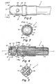
- FIG. 1 illustrates an overview of a mapping and ablation catheter system for use in electrophysiology procedures.
- the system includes a catheter 1 having a shaft portion 3, a control handle 5, and a connector portion 7.
- connector portion 7 is used to allow signal wires running from mapping electrodes at the distal end 6 of the catheter to be connected to a device for recording signals, such as a recording device 17.
- a device for recording signals such as a recording device 17.
- connector portion 7 is used to allow signal wires running from ablation electrodes at the distal end 6 of the catheter to be connected to a device for generating ablation energy, such as ablation energy generator 13.
- a controller 9 is electrically connected to connector portion 7 via cable 11.
- controller 9 may be a QUADRAPULSE RF CONTROLLERTM device available from C.R. Bard, Inc., Murray Hill, New Jersey.
- Ablation energy generator 13 may be connected to controller 9 via cable 15.
- Recording device 17 may be connected to controller 9 via cable 19.
- controller 9 is used to control ablation energy, provided by ablation energy generator 13, to catheter 1.
- controller 9 is used to process signals from catheter 1 and provide these signals to recording device 17.
- recording device 17, ablation energy generator 13, and controller 9 may be incorporated into a single device. It should further be appreciated that although both ablation energy generator 13 and recording device 17 are illustrated in Figure 1 , either or both of these devices may be incorporated in the catheter system.
- the shaft portion 3 of the catheter 1 is, in one embodiment, approximately seven French in diameter, although it should be appreciated that many diameters are possible, and the diameter of shaft portion 3 may be smaller or larger depending on the particular application and/or combination of features incorporated into the catheter.
- Shaft portion 3 includes a distal cap portion 21 having a plurality of, for example, two or more electrodes. As will be subsequently described, the electrodes may be arranged in a number of different configurations and may include mapping and/or ablation electrodes. According to one embodiment of the invention, distal cap portion 21 is approximately eight mm in length.
- Distal cap portion 21 is provided, in the illustrated embodiment, with a first set of mapping electrodes 47, a second set of mapping electrodes 49, and a band electrode 51.
- the electrodes may be formed of any suitable bio-compatible, electrically conductive material (e.g., platinum, gold, titanium, iridium, stainless steel).
- the mapping electrodes 47, 49 are approximately 0.5-1.5 mm in diameter, through they may be either larger or smaller according to the invention.
- the size of mapping electrodes 47, 49 is in part determined based on considerations of signal quality, which improves as electrode size increases and as electrode isolation (i.e., distance between electrodes) increases.
- mapping electrodes 47, 49 are shown having a circular shape. However, mapping electrodes 47, 49 may alternatively be square, oval, hexagonal, octagonal, or any other shape that may be readily imagined by one skilled in the art. Further, though mapping electrodes 47, 49 are also shown in Figure 2 , as well as Figures 3-5 and 7-12 , as dome-ahaped, the mapping electrodes of any of the illustrated embodiments may alternatively be flat so that they are more-closely flush with the surface of the distale cap portion 21, as shown, for example, by mapping electrodes 48, 50 in Figure 6 . Band electrode 51 is shown in Figure 2 as flat, but may alternatively have a curved surface.
- Figures 4 and 5 respectively illustrate a cross-sectional side view of the distal cap portion 21 of catheter 1 along line 4-4 of Figure 3 , and a cross-sectional axial view of the distal cap portion 21 of catheter 1 along line 5-5 of Figure 4 .
- wires 52, 53, 54 respectively connect to each of the electrodes 47, 49, 51 of the catheter 1.
- These wires 52, 53, 54 which may be between 3/1000 mm and 20/1000 mm, allow electrical signals information to be transmitted from mapping electrodes 47, 49 and band electrode 51, when used in a mapping application, to connector portion 7, which in turn connects to controller 9 ( Figure 1 ).
- the wire 54 connected thereto may be used to transmit ablation energy from ablation energy generator 13 to the electrode via connector portion 7.
- the wires 52, 53, 54 are connected to the electrodes by soldering, welding, or any other suitable mechanism for connecting the wires to the electrodes to form an electrical connection 55.
- Mapping electrodes 47, 49 may be substantially mushroom-shaped, and may have a substantially cylindrical "stem" portion 48. As shown in Figures 4 and 5 , the cylindrical stem 48 of each electrode 47, 49 may have a larger diameter at the base 46 of the stem, so that the electrode is prevented from dislodging from the distal cap portion 21.
- Distal cap portion 21 may also be countersunk at the location of each electrode, 60 that the electrodes are disposed within a recessed portion of the distal cap portion 21.
- Mapping electrodes 47, 49 and band electrode 51 are disposed in apertures within a distal cap 57, which covers the distal cap portion 21 of the catheter 1.
- the distal cap 57 may be, in one arrangement not according to the present invention, formed of any non-electrically conductive, bio-compatible material.
- distal cap 57 maybe formed of polyamide, epoxy, plastic, nylon, or any other suitable material. In addition to providing a durable surface, distal cap 57 isolates each of the electrodes on distal cap portion 21 from each other.
- the distal cap portion 21 is provided with a pair of mapping electrodes 47 at the distal end of catheter 1.
- the pair of mapping electrodes 47 are disposed on the dome-shaped portion 20 of the distal cap 57, but not on the cylindrically-shaped portion 22 of the distal cap 57. Further, the mapping electrodes 47 may be positioned, in one embodiment, at a 45° angle with respect to an axis C-C that extends longitudinally along the length of catheter. 1, through its center.
- the mapping electrodes 47 may be separated by a distance of approximately 1 mm. One skilled in the art will appreciate that other angles and separation distances for mapping electrodes 47 may be provided.
- the pair of mapping electrodes 47 may be used to determine, for example, a location of lowest conductivity on the septal wall, or a preferred location to puncture the septal wall during a transeptal procedure.
- Each of the mapping electrodes 47 may detect a voltage signal, which is transmitted to controller 9 via wires 53. Voltage may be measured instantaneously or continuously by each of the electrodes 47. Continuous voltage measurements generate an electrogram (a voltage signal that changes with time) for each electrode 47.
- the voltage detected by each electrode 47 may be determined with respect to a preference electrode, termed a unipolar voltage measurement, or may be determined with respect to the other electrode 47 of the pair, termed a bipolar voltage measurement.
- the pair of mapping electrodes 47 may generate two unipolar electrograms, each with respect to a reference electrode located elsewhere on the catheter 1, or a single bipolar electrogram representing the voltage between each of the electrodes 47 of the pair.
- the use of two electrodes 47 enables the voltage between the electrodes to be determined
- the use of two electrodes enables an additional data point for locating the preferred site of puncture. For example, if a first electrode of the pair detects a lower amplitude signal than the second electrode of the pair, this information can be used to indicate that the distal cap portion 21 of catheter 1 should be moved in the direction of the first electrode, towards the lower amplitude signal. It should be appreciated that while the electrodes 47 are described as a pair of electrodes, a single electrode or more than two electrodes may alternately be used on the distal cap portion 21.
- a point of reduced conductivity is represented by a reduced or minimized voltage signal from one or more of the electrodes 47. This point may be detected by a computer algorithm and/or a human operator.
- the controller 9 may implement an algorithm that integrates the continuous voltage signal over a period of time and compares the resultant value with a predetermined value or with other calculated values to determine whether the voltage signal is sufficiently low so as to indicate a point of lowest conductivity or a preferred site of puncture.
- electrodes approximately one mm in size, spaced approximately one mm apart and set at approximately 45° with respect to axis c-c advantageously allows for accurate determination of the foramen ovale during transeptal procedures.
- the distal cap portion 21 is provided with a group of mapping electrodes 49 circumferentially disposed about the distal cap portion 21 of catheter 1.
- the group of mapping electrodes 49 are disposed on the cylindrically-shaped portion 22 of the distal cap portion 21 in a plane normal to the axis C-C ( Figure 4 ).
- the mapping electrodes 49 may be equidistant from each other and may be separated by a distance of at least half of the diameter of each electrode.
- the group of mapping electrodes 49 includes four electrodes, though other numbers of electrodes (e.g., two, three, five, six) are also possible.
- the distal cap portion 21 is provided with a plurality of groups of mapping electrodes 49 circumferentially disposed about the distal cap portion 21 of catheter 1.
- catheter 1 may be provided with four groups of mapping electrodes 49, which may, for example, comprise four electrodes each.
- the spacing of groups of electrodes 49 is, in one embodiment, approximately two millimeters.
- mapping electrodes 49 may be used to determine the intensity, direction, and velocity of electrical signals of the heart.
- the group configuration of mapping electrodes 49 provides advantages over certain electrodes, e.g., band electrodes, which do not allow the same degree of differentiation between signals. For example, a band electrode cannot differentiate signals received from a various regions of the circumference of the catheter. In contrast, a group of four electrodes allows differentiation between signals from each quadrant of the circumference of the catheter, and therefore provides more directional information than a band electrode. Multiple groups of mapping electrodes 49 allows a greater degree of differentiation between signals received at various points along the length of a catheter.
- mapping electrodes also allows for differentiation between signals of local and remote origin, based on a comparison of signals received by adjacent electrodes. For example, if a signal is measured more weakly by each successive adjacent electrode, and received after a constant time lapse by each successive electrode, one may determine that the signal is of remote origin (i.e., a "far-field" signal).
- mapping electrode 49 can provide a high resolution mapping catheter.
- the distal cap portion 21 is provided with a row of mapping electrodes 61 disposed along the length of distal cap portion 21.
- each electrode 61 may be equidistant from each adjacent electrode disposed along the length of the catheter 1.
- the electrodes 61 may be similar to the electrodes of other embodiments, and may be approximately between 0.5 and 1.5 mm in diameter.
- the catheter is provided with four mapping electrodes 61 disposed on the circumference of distal cap portion 21, although more or fewer mapping electrodes 61 may be used.
- the spacing of the electrodes 61 is, in one embodiment, approximately one mm.
- the rows of mapping electrodes 61 that extend along the length of distal cap portion 21 may be used to determine the continuity of a line of lesions, e.g., formed by the "drag and burn" ablation technique.
- a voltage signal may be measured between each of the adjacent mapping electrodes 61 in a row of electrodes.
- the controller 9 may process each voltage signal and, for example, determine whether the voltage level for each signal exceeds a certain threshold, indicating that a gap in the lesions may exist.
- the row of mapping electrodes 61 may be used to determine the conductivity of the heart tissue in contact with the electrodes for any portion of heart tissue between any adjacent or non-adjacent pair of electrodes 61.
- the distal cap portion 21 is provided with a band-shaped electrode disposed on the distal cap 57 of catheter 1.
- the band-shaped electrode 51 may serve as a reference electrode for other electrodes on the catheter 1, whereby other voltages of other electrodes are determined relative to band-shaped electrode 51.
- the band-shaped electrode serves as an ablation electrode and is provided with ablation energy to perform ablation.
- Figure 6 illustrates a band-shaped ablation electrode 63.
- the band-shaped ablation electrode 63 may be provided with RF energy for ablation, and may be at least 4 mm in length to facilitate ablation.
- a band-shaped ablation electrode and a band-shaped temperature sensor are provided.
- Temperature sensor 67 may be a thermocouple, thermistor, or any other device for sensing temperature.
- the temperature sensor 67 detects the heat of the tissue during ablation by band-shaped ablation electrode 65. Temperature sensing is important during ablation because overheated tissue may explode or char, releasing debris into the bloodstream.
- Band-shaped ablation electrode 65 is connected to connector portion 7 via wire 66, which in turn connects to ablation energy generator 13; band-shaped temperature sensor 67 is connected to connector portion 7 via wire 68, which in turn connects to ablation controller 9.
- Band-shaped electrode 51 can serve as both a reference electrode and an ablation electrode, and may be switched between applications by the controller 9 or by a human operator.
- Distal cap 57 has, up to this point, been described as being non-electrically conductive. However, in accordance with the present invention, distal cap 57 is constructed of an electrically conductive material, specifically a metal material.
- distal cap 57 is disposed about mapping electrodes 47, 49 and band-shaped electrode 51.
- Distal cap 57 is connected via wire 75 to connector portion 7, which in turn connects to the ablation energy generator 13.
- Distal cap 57 may be formed of any suitable bio-compatible, electrically conductive metallic material (e. g., platinum, gold, titanium, iridium, stainless steel).
- insulating sleeves 77 and insulating sleeves 79 are respectively provided. Insulating sleeves 77 and insulating sleeves 79 may extend beyond mapping electrodes 47,49 and band-shaped electrode 51 over the surface of distal cap 57 in a gasket-like formation.
- RF energy may concentrate at the edges of the apertures distal cap 57. Insulation of the edge regions from tissue contact can prevent the delivery of excess ablation energy to the tissue from the edge regions of the distal cap 57.
- Conductive distal cap 57 may be used to deliver ablation, energy to a desired area of tissue.
- the ablation energy can be, for example, RF, DC, ultrasound, microwave, or laser radiation.
- Ablation may be performed in a blood vessel, e. g., the pulmonary vein, or an area of the heart, e. g., the left atrium.
- Ablation energy may be applied via the distal cap 57, to ablate the tissue that is in contact with the distal cap portion 21. For example, if an electrode on distal cap portion 21 detects an arrhythmia focus site in the vicinity of the electrode, the region of the distal cap 57 that is closest to the electrode may be used to ablate the tissue.
- repositioning of the catheter 1 is not necessary between detection of an arrhythmia focus site via a mapping electrode and ablation of the arrhythmia focus site via conductive distal cap 57. Further, because ablation can be confined to the particular region of interest, large areas of tissue need not be ablated, resulting in less extensive tissue scarring.
- the embodiment illustrated in Figure 12 has several advantages.
- the catheter is able to provide two functions, mapping and ablation, in a single catheter wherein the catheter is constructed and arranged to provide each of these functions individually and independently.
- the design of the catheter for high resolution mapping functions does not adversely impact the design for ablation functions.
- the catheter can be constructed so as to optimize each function.
- the small size and location of each mapping electrode 49 on the distal cap portion 21 may be chosen to provide the ability to measure electrical activity with high resolution and an appropriate level of tissue contact, but without interference from either adjacent electrodes or other tissue not of interest.
- Conductive distal cap 57 is able to meet these requirements since its surface area and mass are significantly larger than the mapping electrodes 49. Incorporating the small mapping electrodes 49 into apertures in the larger conductive distal cap 57 allows mapping and ablation procedures to be performed with a single catheter. In addition, since the mapping electrodes and the conductive distal cap can be operated independently, mapping and ablation procedures can be performed at the same time or in any desired sequence, such as before, during, and/or after each other.
- Catheter 1 may be a steerable device. Reference is again made to Figure 1 , for description of one possible implementation for a steering mechanism for catheter 1.
- Catheter 1 is connected to catheter handle 5, which enables steering control of the distal end of catheter 1.
- a control switch 23 is mechanically coupled to a steering wire 25, which is in turn mechanically coupled to the distal cap portion 21 of the catheter 1.
- an anchor 59 may be provided in the distal cap portion 21 to fix the steering wire 25 to the inside of the catheter 1. The tension on the steering wire 25 may be adjusted by the control switch 23 to adjust a flexible portion of the distal end of the catheter 1.
- control switch 23 may be maneuvered laterally along the control handle 5 to control the curvature of the distal end of the catheter 1.
- control switch 23 may be slid towards the proximal end of catheter 1 to move the distal end of the catheter 1 to position 27, and towards the distal end of control handle 5 to move the distal end of the catheter 1 to position 29.
- the control switch 23 may be slid to a position midway between the forward and backwards positions to orient the distal end of the catheter 1 in an uncurved position.
- the catheter may be steered in any number of directions, in one or more planes.
- control may be implemented electrically such that motion of a control switch 23 along the length of the control handle 5 is not required.
- Control may be implemented on the control handle 5, or via a device external to the catheter assembly.
- U. S. Patent Numbers 5,383,852 , 5,462,527 , and 5,611,777 illustrate various additional embodiments and features of control handle 5 that may be used for steering catheter 1.
- Localization refers to a number of techniques whereby the location of catheter 1 in a patient can be determined. Apparatus and methods for localization can be incorporated into catheter 1.
- Electromagnetic sensor 69 may be fixed within the shaft of the catheter 1 using any suitable mechanism, such as glue or solder.
- the electromagnetic sensor 69 generates signals indicative of the location of the electromagnetic sensor.
- a wire 71 electrically connects the electromagnetic sensor 69 to the controller 9, allowing the generated signals to be transmitted to the controller 9 for processing.
- a second electromagnetic sensor (not shown) is provided that is fixed relative to the patient.
- the second electromagnetic sensor is attached, for example, to the patient's body, and serves as a reference sensor.
- a magnetic field is also provided, which is exposed to the electromagnetic sensors. Coils within each electromagnetic sensor generate electrical currents when exposed to the magnetic field. The electrical current generated by the coils of each sensor corresponds to a position of each sensor within the magnetic field. Signals generated by the reference electromagnetic sensor and electromagnetic sensor 69 fixed to the catheter are analyzed by the controller 9 to ascertain a precise location of electromagnetic sensor 69 fixed to the catheter 1.
- the signals can be used to generate a contour map of the heart.
- the map may be generated by contacting the catheter 1 with the heart tissue at a number of locations along the heart wall. At each location, the electric signals generated by the electromagnetic sensors are transmitted to the controller 9, or to another processor, to determine and record a location of the catheter 1.
- the contour map is generated by compiling the location information for each point of contact. This map may be correlated with heart signal data, measured by one or more electrodes on the catheter, for each location to generate a map of both the shape and electrical activity of the heart. Signals generated by the electromagnetic sensors may also be analyzed to determine a displacement of the catheter 1 caused by heartbeat.
- an impedance-based sensor can also be incorporated into catheter 1.
- an impedance-based system several, such as three, high frequency signals are generated along different axes.
- the catheter electrodes may be used to sense these frequencies, and with appropriate filtering, the strength of the signal and thus the position of the catheter can be determined.
- catheter 1 may be optimized to make use of the various localization techniques.
- Irrigation refers to any one of a number of techniques whereby a fluid may be introduced into the vicinity surrounding distal cap 21.
- Apparatus and methods for irrigation can be incorporated into catheter 1.
- the fluid may be a contrast fluid, a cooling fluid (particularly during ablation-procedures), an antithrombogenic fluid, or other medicine.
- a lumen may be provided inside shaft portion 3 that transports the irrigation fluid from the proximal end of catheter 1 to distal cap 21.
- the irrigation fluid may be dispersed into the vicinity surrounding distal cap 21 through apertures provided in the distal cap itself and/or through apertures in catheter shaft portion 3 proximal to distal cap 21.
- one or more of the electrodes in distal cap 49 may be removed and the irrigation fluid directed through the aperture so created.
- the irrigation fluid may be introduced into the vicinity surrounding distal cap 21 by apertures in, for example, insulating sleeves 77.
- Temperature sensing refers to a number of techniques whereby the temperature in the vicinity surrounding distal cap 21 may be measured. Measuring temperature is important, particularly during ablation procedures, so as to avoid overheating or charring tissue.
- the catheter of the present invention can provide for measuring the temperature of the distal cap 21 and the mapping electrodes at the same time. The temperature of the distal cap can then be used to provide feedback for control of ablation energy generator 13 and the temperature of the mapping electrodes can be monitored to be certain that the tissue that is being ablated is in fact being destroyed or rendered non-electrically conductive.
- a temperature sensor or sensors such as, but not limited to one or more thermocouples 81 (illustrated in Figure 12 ) may be attached to the catheter 1 for temperature sensing during ablation procedures.
- a temperature sensor may be in contact with the heart tissue (e.g., temperature sensor 67 of Figure 7 ) or, alternately, may not be in contact with the heart tissue (e.g., temperature sensor 81 of Figure 12 ).
- temperature sensors may be disposed within mapping electrodes 47, 49, 51, for example in a hole drilled within the electrode.
- mapping electrodes 47, 49, 51 for example in a hole drilled within the electrode.
- more than one temperature sensor may be used in any particular configuration of catheter 1.
- the catheter system of the invention may be used in mapping and/or ablation applications.
- the mapping or ablation is performed in the heart of a patient.
- multiple signals may be received from the heart tissue via multiple electrodes on the catheter.
- Each electrode may measure a continuous signal (i.e., electrogram) from the heart tissue.
- the continuous signal may represent the voltage of the heart tissue in contact with the electrode, with respect to a reference voltage, as it changes with time.
- the reference voltage may be obtained using a dedicated reference electrode or another measurement electrode.
- the quality of the signal received by each electrode improves as both the size of the electrode and the isolation of the electrode increases.
- multiple electrodes are employed, such that multiple electrograms may be obtained simultaneously.
- This allows for multiple data points, which can result in a more precise mapping of the heart signal and a shorter required measurement time.
- a shorter measurement time advantageously reduces the x-ray exposure to patients and physicians during fluoroscopy, when employed during the catheter procedure.
- the mapping function of the catheter has a number of different applications.
- the catheter is used to measure the conductivity at various points of the septal wall, which separates the left and right sides of the heart, to determine a preferred sight for puncture of the septal wall.
- the conductivity of the heart tissue is measured between adjacent electrodes in contact with the heart tissue to determine the continuity of a lesion formed by ablation.
- the catheter is used to identify electrical signals within the heart that are characteristic of a number of heart conditions. For example, the focus site of an arrhythmia (e.g. atrial fibrillation, AV nodal tachycardia or tachycardia resulting from Wolff-Parkinson-White syndrome).
- arrhythmia e.g. atrial fibrillation, AV nodal tachycardia or tachycardia resulting from Wolff-Parkinson-White syndrome.
- the signals measured by the electrodes of the catheter may be analyzed by the controller 9. In one method, this analysis may take place in real time. In an alternate method, these signals may be stored in recording device 17 for later analysis. These signals may be processed manually, via a human operator, or may be processed by controller 9 in connection with a processing algorithm. The processing algorithm may compare, add, subtract, or otherwise manipulate measured signals.
- the catheter can also be used for ablation procedures.
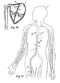
- FIG. 13 illustrates a method of insertion of the catheter 1 into a patient 31.
- the catheter 1 is inserted into the patient via a blood vessel, e.g., subclavian vein, jugular vein, or femoral vein.
- the catheter 1 is shown entering a femoral vein 33 via an incision 35 in the thigh of the patient 31.
- the catheter 1 may be introduced into the vein using a sheath/dilator (not shown).
- the sheath/dilator may be anchored at the incision site, for example by stitching the sheath/dilator to the patient's skin at the area of incision 35.
- the catheter 1 of Figure 13 may be advanced independently, or through a sheath/dilator, up the inferior vena cava 37 into the right atrium of the heart.
- FIG 14 illustrates a diagram of a cross-sectional view of the heart taken along line 14-14 in Figure 13 .
- the catheter 1 is shown entering the right atrium 39 via the inferior vena cava 37.
- the catheter 1 may be passed trans-septally through the septal wall 45.
- a puncture 43 in the septal wall 45 is made at the foramen ovale, an area of the septal wall having a decreased thickness and decreased conductivity relative to other areas of the septal wall.
- electrodes on catheter 1 are used to locate the foramen ovale, or another preferred site to puncture the septal wall.
- the catheter 1 traverses the septal wall 45 from the right atrium 39 and enters the left atrium 41.
- the catheter 1 may be used for mapping and/or ablation procedures in the left atrium 41 or may be maneuvered into the pulmonary vein (s) for mapping and/or ablation. It should be appreciated that the catheter may also be used to perform mapping and/or ablation in the right heart, in the ventricles, or in any other area of the heart or blood vessels of the circulatory system, and that the catheter 1 need not pass through the septal wall to enter these areas.
- One advantage of using a catheter according to the invention in the described method is that only a single catheter is necessary to (1) determine the location of the foramen ovale for passage through the septal wall, (2) perform any desired mapping procedures, and (3) perform any desired ablation procedures. This avoids the need for changing catheters during procedures as between, for example, mapping and ablation procedures. It may also reduce the number of removal and reinsertion operations needed during a patient's electrophysiology study and treatment procedure.
- mapping electrodes and the ablation electrodes can be provided depending upon the particular application.
Claims (14)
- Katheter (1), Folgendes umfassend:eine Metallkappe (57), die mehrere Öffnungen umfasst; undwenigstens eine Elektrode (47, 49), die dafür eingerichtet ist, ein elektrisches Signal zu erfassen, und die in jeder Öffnung von den mehreren Öffnungen angeordnet sind, wobei die Elektroden (47, 49) von der Kappe isoliert sind.
- Katheter (1) nach Anspruch 1, wobei die wenigstens eine Elektrode (47, 49) elektrische Signale des Herzens detektiert.
- Katheter (1) nach Anspruch 1, wobei die wenigstens eine Elektrode (47, 49) Spannungssignale detektiert.
- Katheter (1) nach einem der Ansprüche 1 bis 3, wobei die Elektroden (47, 49) sich über eine Oberfläche der Kappe (57) hinaus erstrecken.
- Katheter (1) nach einem der Ansprüche 1 bis 4, wobei die Elektroden (47, 49) pilzförmig sind.
- Katheter (1) nach einem der Ansprüche 1 bis 5, wobei die Elektroden (47, 49) kuppelförmig sind.
- Katheter (1) nach einem der Ansprüche 1 bis 6, wobei die Kappe (57) aus einem Metall ist, das aus der Gruppe gewählt ist, die Gold und Platin umfasst.
- Katheter (1) nach einem der Ansprüche 1 bis 7, der außerdem Folgendes umfasst: ein Mittel (23) zum Steuern eines distalen Endes des Katheters (1).
- Katheter (1) nach Anspruch 8, wobei das Mittel (23) zum Steuern ein Mittel zum Steuern eines distalen Endes des Katheters (1) in wenigstens einer Ebene umfasst.
- Katheter (1) nach einem der Ansprüche 1 bis 9, wobei die Metallkappe (57) dafür konzipiert und eingerichtet ist, Ablationsvorgänge zu optimieren und wobei eine Konfiguration der Elektroden (47, 49) danach ausgewählt ist, Mappingvorgänge zu optimieren.
- Katheter (1) nach einem der Ansprüche 1 bis 10, wobei ein Oberflächeninhalt der Metallkappe (57) größer ist als ein Oberflächeninhalt der wenigstens einen Elektrode (47, 49).
- Katheter (1) nach einem der Ansprüche 1 bis 11, der außerdem Folgendes umfasst: einen Temperatursensor (67) zum Erfassen der Temperatur in einer Umgebung der Metallkappe (57).
- Katheter (1) nach einem der Ansprüche 1 bis 12, der außerdem Folgendes umfasst: einen Positionssensor (69) zum Identifizieren einer Position des Katheters (1).
- Katheter (1) nach den Ansprüchen 1 bis 13, der außerdem Folgendes umfasst: ein Mittel zum Versorgen einer Umgebung des Katheters (1) mit einem Fluid.
Applications Claiming Priority (3)
| Application Number | Priority Date | Filing Date | Title |
|---|---|---|---|
| US25463000P | 2000-12-11 | 2000-12-11 | |
| US254630P | 2000-12-11 | ||
| PCT/US2001/048120 WO2002047569A1 (en) | 2000-12-11 | 2001-12-11 | Microelectrode catheter for mapping and ablation |
Publications (2)
| Publication Number | Publication Date |
|---|---|
| EP1343426A1 EP1343426A1 (de) | 2003-09-17 |
| EP1343426B1 true EP1343426B1 (de) | 2012-10-24 |
Family
ID=22965008
Family Applications (2)
| Application Number | Title | Priority Date | Filing Date |
|---|---|---|---|
| EP01990167A Expired - Lifetime EP1343426B1 (de) | 2000-12-11 | 2001-12-11 | Mikroelekroden katheter zur ablation und einteilung |
| EP01993250A Expired - Lifetime EP1343427B1 (de) | 2000-12-11 | 2001-12-11 | Vorrichtung zum mapping |
Family Applications After (1)
| Application Number | Title | Priority Date | Filing Date |
|---|---|---|---|
| EP01993250A Expired - Lifetime EP1343427B1 (de) | 2000-12-11 | 2001-12-11 | Vorrichtung zum mapping |
Country Status (4)
| Country | Link |
|---|---|
| EP (2) | EP1343426B1 (de) |
| AT (1) | ATE333843T1 (de) |
| DE (1) | DE60121800T2 (de) |
| WO (2) | WO2002047569A1 (de) |
Cited By (14)
| Publication number | Priority date | Publication date | Assignee | Title |
|---|---|---|---|---|
| US8945015B2 (en) | 2012-01-31 | 2015-02-03 | Koninklijke Philips N.V. | Ablation probe with fluid-based acoustic coupling for ultrasonic tissue imaging and treatment |
| US9089340B2 (en) | 2010-12-30 | 2015-07-28 | Boston Scientific Scimed, Inc. | Ultrasound guided tissue ablation |
| US9211156B2 (en) | 2012-09-18 | 2015-12-15 | Boston Scientific Scimed, Inc. | Map and ablate closed-loop cooled ablation catheter with flat tip |
| US9241687B2 (en) | 2011-06-01 | 2016-01-26 | Boston Scientific Scimed Inc. | Ablation probe with ultrasonic imaging capabilities |
| US9241761B2 (en) | 2011-12-28 | 2016-01-26 | Koninklijke Philips N.V. | Ablation probe with ultrasonic imaging capability |
| US9370329B2 (en) | 2012-09-18 | 2016-06-21 | Boston Scientific Scimed, Inc. | Map and ablate closed-loop cooled ablation catheter |
| US9393072B2 (en) | 2009-06-30 | 2016-07-19 | Boston Scientific Scimed, Inc. | Map and ablate open irrigated hybrid catheter |
| US9463064B2 (en) | 2011-09-14 | 2016-10-11 | Boston Scientific Scimed Inc. | Ablation device with multiple ablation modes |
| US9603659B2 (en) | 2011-09-14 | 2017-03-28 | Boston Scientific Scimed Inc. | Ablation device with ionically conductive balloon |
| US9743854B2 (en) | 2014-12-18 | 2017-08-29 | Boston Scientific Scimed, Inc. | Real-time morphology analysis for lesion assessment |
| US9757191B2 (en) | 2012-01-10 | 2017-09-12 | Boston Scientific Scimed, Inc. | Electrophysiology system and methods |
| US10524684B2 (en) | 2014-10-13 | 2020-01-07 | Boston Scientific Scimed Inc | Tissue diagnosis and treatment using mini-electrodes |
| US10603105B2 (en) | 2014-10-24 | 2020-03-31 | Boston Scientific Scimed Inc | Medical devices with a flexible electrode assembly coupled to an ablation tip |
| US11684416B2 (en) | 2009-02-11 | 2023-06-27 | Boston Scientific Scimed, Inc. | Insulated ablation catheter devices and methods of use |
Families Citing this family (21)
| Publication number | Priority date | Publication date | Assignee | Title |
|---|---|---|---|---|
| US7097644B2 (en) | 2001-03-30 | 2006-08-29 | Ethicon Endo-Surgery, Inc. | Medical device with improved wall construction |
| US20030181900A1 (en) * | 2002-03-25 | 2003-09-25 | Long Gary L. | Endoscopic ablation system with a plurality of electrodes |
| US20020183739A1 (en) | 2001-03-30 | 2002-12-05 | Long Gary L. | Endoscopic ablation system with sealed sheath |
| US7137981B2 (en) | 2002-03-25 | 2006-11-21 | Ethicon Endo-Surgery, Inc. | Endoscopic ablation system with a distally mounted image sensor |
| US20040133113A1 (en) | 2002-08-24 | 2004-07-08 | Krishnan Subramaniam C. | Method and apparatus for locating the fossa ovalis and performing transseptal puncture |
| US20040082947A1 (en) | 2002-10-25 | 2004-04-29 | The Regents Of The University Of Michigan | Ablation catheters |
| US7163537B2 (en) | 2003-06-02 | 2007-01-16 | Biosense Webster, Inc. | Enhanced ablation and mapping catheter and method for treating atrial fibrillation |
| NL1026422C2 (nl) * | 2004-06-15 | 2005-12-19 | Univ Eindhoven Tech | Inrichting voor het creeren van een lokaal koud plasma ter plaatse van een object. |
| US7232438B2 (en) | 2004-07-09 | 2007-06-19 | Ethicon Endo-Surgery, Inc. | Ablation device with clear probe |
| US20060089637A1 (en) | 2004-10-14 | 2006-04-27 | Werneth Randell L | Ablation catheter |
| US8617152B2 (en) | 2004-11-15 | 2013-12-31 | Medtronic Ablation Frontiers Llc | Ablation system with feedback |
| US7429261B2 (en) | 2004-11-24 | 2008-09-30 | Ablation Frontiers, Inc. | Atrial ablation catheter and method of use |
| US7468062B2 (en) | 2004-11-24 | 2008-12-23 | Ablation Frontiers, Inc. | Atrial ablation catheter adapted for treatment of septal wall arrhythmogenic foci and method of use |
| EP1895927A4 (de) | 2005-06-20 | 2011-03-09 | Medtronic Ablation Frontiers | Ablationskatheter |
| WO2007008954A2 (en) | 2005-07-11 | 2007-01-18 | Ablation Frontiers | Low power tissue ablation system |
| US8657814B2 (en) | 2005-08-22 | 2014-02-25 | Medtronic Ablation Frontiers Llc | User interface for tissue ablation system |
| US8641704B2 (en) | 2007-05-11 | 2014-02-04 | Medtronic Ablation Frontiers Llc | Ablation therapy system and method for treating continuous atrial fibrillation |
| US9119636B2 (en) | 2011-06-27 | 2015-09-01 | Boston Scientific Scimed Inc. | Dispersive belt for an ablation system |
| US20150328448A1 (en) * | 2014-05-13 | 2015-11-19 | Biotronik Ag | Electrode element for electromedical therapy in a human or animal body |
| EP3359073B1 (de) * | 2015-11-20 | 2020-02-12 | St. Jude Medical, Cardiology Division, Inc. | Ablatorspitze mit mehreren elektroden mit fähigkeiten zur doppelmodalen, omnidirektionalen rückmeldung |
| CN114366286A (zh) * | 2022-01-27 | 2022-04-19 | 四川锦江电子科技有限公司 | 消融导管 |
Citations (1)
| Publication number | Priority date | Publication date | Assignee | Title |
|---|---|---|---|---|
| EP0965302A2 (de) * | 1998-06-18 | 1999-12-22 | Cordis Webster, Inc. | Multielement-Spitzenelektroden für Kartierungskatheter |
Family Cites Families (10)
| Publication number | Priority date | Publication date | Assignee | Title |
|---|---|---|---|---|
| US5370675A (en) * | 1992-08-12 | 1994-12-06 | Vidamed, Inc. | Medical probe device and method |
| WO1993008755A1 (en) | 1991-11-08 | 1993-05-13 | Ep Technologies, Inc. | Ablation electrode with insulated temperature sensing elements |
| US5366443A (en) * | 1992-01-07 | 1994-11-22 | Thapliyal And Eggers Partners | Method and apparatus for advancing catheters through occluded body lumens |
| US5697882A (en) * | 1992-01-07 | 1997-12-16 | Arthrocare Corporation | System and method for electrosurgical cutting and ablation |
| US5462527A (en) | 1993-06-29 | 1995-10-31 | C.R. Bard, Inc. | Actuator for use with steerable catheter |
| US5383852A (en) | 1992-12-04 | 1995-01-24 | C. R. Bard, Inc. | Catheter with independent proximal and distal control |
| US5611777A (en) | 1993-05-14 | 1997-03-18 | C.R. Bard, Inc. | Steerable electrode catheter |
| WO1997012548A1 (en) * | 1995-10-06 | 1997-04-10 | Cordis Webster, Inc. | Split tip electrode catheter |
| US5779699A (en) * | 1996-03-29 | 1998-07-14 | Medtronic, Inc. | Slip resistant field focusing ablation catheter electrode |
| WO1999000060A1 (en) * | 1997-06-26 | 1999-01-07 | Advanced Coronary Intervention | Electrosurgical catheter for resolving obstructions by radio frequency ablation |
-
2001
- 2001-12-11 WO PCT/US2001/048120 patent/WO2002047569A1/en not_active Application Discontinuation
- 2001-12-11 EP EP01990167A patent/EP1343426B1/de not_active Expired - Lifetime
- 2001-12-11 WO PCT/US2001/047888 patent/WO2002056783A1/en active IP Right Grant
- 2001-12-11 DE DE60121800T patent/DE60121800T2/de not_active Expired - Lifetime
- 2001-12-11 AT AT01993250T patent/ATE333843T1/de not_active IP Right Cessation
- 2001-12-11 EP EP01993250A patent/EP1343427B1/de not_active Expired - Lifetime
Patent Citations (1)
| Publication number | Priority date | Publication date | Assignee | Title |
|---|---|---|---|---|
| EP0965302A2 (de) * | 1998-06-18 | 1999-12-22 | Cordis Webster, Inc. | Multielement-Spitzenelektroden für Kartierungskatheter |
Cited By (15)
| Publication number | Priority date | Publication date | Assignee | Title |
|---|---|---|---|---|
| US11684416B2 (en) | 2009-02-11 | 2023-06-27 | Boston Scientific Scimed, Inc. | Insulated ablation catheter devices and methods of use |
| US9393072B2 (en) | 2009-06-30 | 2016-07-19 | Boston Scientific Scimed, Inc. | Map and ablate open irrigated hybrid catheter |
| US9089340B2 (en) | 2010-12-30 | 2015-07-28 | Boston Scientific Scimed, Inc. | Ultrasound guided tissue ablation |
| US9241687B2 (en) | 2011-06-01 | 2016-01-26 | Boston Scientific Scimed Inc. | Ablation probe with ultrasonic imaging capabilities |
| US9463064B2 (en) | 2011-09-14 | 2016-10-11 | Boston Scientific Scimed Inc. | Ablation device with multiple ablation modes |
| US9603659B2 (en) | 2011-09-14 | 2017-03-28 | Boston Scientific Scimed Inc. | Ablation device with ionically conductive balloon |
| US9241761B2 (en) | 2011-12-28 | 2016-01-26 | Koninklijke Philips N.V. | Ablation probe with ultrasonic imaging capability |
| US9757191B2 (en) | 2012-01-10 | 2017-09-12 | Boston Scientific Scimed, Inc. | Electrophysiology system and methods |
| US8945015B2 (en) | 2012-01-31 | 2015-02-03 | Koninklijke Philips N.V. | Ablation probe with fluid-based acoustic coupling for ultrasonic tissue imaging and treatment |
| US9370329B2 (en) | 2012-09-18 | 2016-06-21 | Boston Scientific Scimed, Inc. | Map and ablate closed-loop cooled ablation catheter |
| US9211156B2 (en) | 2012-09-18 | 2015-12-15 | Boston Scientific Scimed, Inc. | Map and ablate closed-loop cooled ablation catheter with flat tip |
| US10524684B2 (en) | 2014-10-13 | 2020-01-07 | Boston Scientific Scimed Inc | Tissue diagnosis and treatment using mini-electrodes |
| US11589768B2 (en) | 2014-10-13 | 2023-02-28 | Boston Scientific Scimed Inc. | Tissue diagnosis and treatment using mini-electrodes |
| US10603105B2 (en) | 2014-10-24 | 2020-03-31 | Boston Scientific Scimed Inc | Medical devices with a flexible electrode assembly coupled to an ablation tip |
| US9743854B2 (en) | 2014-12-18 | 2017-08-29 | Boston Scientific Scimed, Inc. | Real-time morphology analysis for lesion assessment |
Also Published As
| Publication number | Publication date |
|---|---|
| WO2002047569A1 (en) | 2002-06-20 |
| ATE333843T1 (de) | 2006-08-15 |
| EP1343427B1 (de) | 2006-07-26 |
| WO2002056783A1 (en) | 2002-07-25 |
| EP1343426A1 (de) | 2003-09-17 |
| EP1343427A1 (de) | 2003-09-17 |
| DE60121800D1 (de) | 2006-09-07 |
| DE60121800T2 (de) | 2007-01-04 |
Similar Documents
| Publication | Publication Date | Title |
|---|---|---|
| US7047068B2 (en) | Microelectrode catheter for mapping and ablation | |
| EP1343426B1 (de) | Mikroelekroden katheter zur ablation und einteilung | |
| US20040092806A1 (en) | Microelectrode catheter for mapping and ablation | |
| AU2015234342B2 (en) | Dual-purpose lasso catheter with irrigation field of the invention | |
| EP2136702B1 (de) | Elektrophysiologischer katheter mit hoher auflösung | |
| US8945116B2 (en) | Mapping and ablation method for the treatment of ventricular tachycardia | |
| EP1502555B1 (de) | Vorrichtung zum Mapping und zur Ablation der Pulmonarvene | |
| US6259941B1 (en) | Intravascular ultrasound locating system | |
| US9149198B2 (en) | Multi-array monophasic potential medical device | |
| US20140058375A1 (en) | High resolution map and ablate catheter | |
| EP3518741B1 (de) | Katheter zur abbildung und/oder zur ablation mit einer geschlossenen endschleife | |
| US20240099660A1 (en) | High Density Paddle Catheter With Distal Coupler and Distal Electrode |
Legal Events
| Date | Code | Title | Description |
|---|---|---|---|
| PUAI | Public reference made under article 153(3) epc to a published international application that has entered the european phase |
Free format text: ORIGINAL CODE: 0009012 |
|
| 17P | Request for examination filed |
Effective date: 20030709 |
|
| AK | Designated contracting states |
Kind code of ref document: A1 Designated state(s): AT BE CH CY DE DK ES FI FR GB GR IE IT LI LU MC NL PT SE TR |
|
| 17Q | First examination report despatched |
Effective date: 20080508 |
|
| GRAP | Despatch of communication of intention to grant a patent |
Free format text: ORIGINAL CODE: EPIDOSNIGR1 |
|
| GRAS | Grant fee paid |
Free format text: ORIGINAL CODE: EPIDOSNIGR3 |
|
| GRAA | (expected) grant |
Free format text: ORIGINAL CODE: 0009210 |
|
| AK | Designated contracting states |
Kind code of ref document: B1 Designated state(s): AT BE CH CY DE DK ES FI FR GB GR IE IT LI LU MC NL PT SE TR |
|
| REG | Reference to a national code |
Ref country code: GB Ref legal event code: FG4D |
|
| REG | Reference to a national code |
Ref country code: CH Ref legal event code: EP |
|
| REG | Reference to a national code |
Ref country code: AT Ref legal event code: REF Ref document number: 580472 Country of ref document: AT Kind code of ref document: T Effective date: 20121115 |
|
| REG | Reference to a national code |
Ref country code: IE Ref legal event code: FG4D |
|
| REG | Reference to a national code |
Ref country code: DE Ref legal event code: R096 Ref document number: 60147282 Country of ref document: DE Effective date: 20121220 |
|
| REG | Reference to a national code |
Ref country code: AT Ref legal event code: MK05 Ref document number: 580472 Country of ref document: AT Kind code of ref document: T Effective date: 20121024 |
|
| REG | Reference to a national code |
Ref country code: NL Ref legal event code: VDEP Effective date: 20121024 |
|
| PG25 | Lapsed in a contracting state [announced via postgrant information from national office to epo] |
Ref country code: SE Free format text: LAPSE BECAUSE OF FAILURE TO SUBMIT A TRANSLATION OF THE DESCRIPTION OR TO PAY THE FEE WITHIN THE PRESCRIBED TIME-LIMIT Effective date: 20121024 Ref country code: FI Free format text: LAPSE BECAUSE OF FAILURE TO SUBMIT A TRANSLATION OF THE DESCRIPTION OR TO PAY THE FEE WITHIN THE PRESCRIBED TIME-LIMIT Effective date: 20121024 Ref country code: NL Free format text: LAPSE BECAUSE OF FAILURE TO SUBMIT A TRANSLATION OF THE DESCRIPTION OR TO PAY THE FEE WITHIN THE PRESCRIBED TIME-LIMIT Effective date: 20121024 |
|
| PG25 | Lapsed in a contracting state [announced via postgrant information from national office to epo] |
Ref country code: BE Free format text: LAPSE BECAUSE OF FAILURE TO SUBMIT A TRANSLATION OF THE DESCRIPTION OR TO PAY THE FEE WITHIN THE PRESCRIBED TIME-LIMIT Effective date: 20121024 Ref country code: GR Free format text: LAPSE BECAUSE OF FAILURE TO SUBMIT A TRANSLATION OF THE DESCRIPTION OR TO PAY THE FEE WITHIN THE PRESCRIBED TIME-LIMIT Effective date: 20130125 Ref country code: PT Free format text: LAPSE BECAUSE OF FAILURE TO SUBMIT A TRANSLATION OF THE DESCRIPTION OR TO PAY THE FEE WITHIN THE PRESCRIBED TIME-LIMIT Effective date: 20130225 Ref country code: CY Free format text: LAPSE BECAUSE OF FAILURE TO SUBMIT A TRANSLATION OF THE DESCRIPTION OR TO PAY THE FEE WITHIN THE PRESCRIBED TIME-LIMIT Effective date: 20121024 |
|
| PG25 | Lapsed in a contracting state [announced via postgrant information from national office to epo] |
Ref country code: AT Free format text: LAPSE BECAUSE OF FAILURE TO SUBMIT A TRANSLATION OF THE DESCRIPTION OR TO PAY THE FEE WITHIN THE PRESCRIBED TIME-LIMIT Effective date: 20121024 |
|
| PG25 | Lapsed in a contracting state [announced via postgrant information from national office to epo] |
Ref country code: DK Free format text: LAPSE BECAUSE OF FAILURE TO SUBMIT A TRANSLATION OF THE DESCRIPTION OR TO PAY THE FEE WITHIN THE PRESCRIBED TIME-LIMIT Effective date: 20121024 Ref country code: MC Free format text: LAPSE BECAUSE OF NON-PAYMENT OF DUE FEES Effective date: 20121231 |
|
| REG | Reference to a national code |
Ref country code: CH Ref legal event code: PL |
|
| PG25 | Lapsed in a contracting state [announced via postgrant information from national office to epo] |
Ref country code: IT Free format text: LAPSE BECAUSE OF FAILURE TO SUBMIT A TRANSLATION OF THE DESCRIPTION OR TO PAY THE FEE WITHIN THE PRESCRIBED TIME-LIMIT Effective date: 20121024 |
|
| PLBE | No opposition filed within time limit |
Free format text: ORIGINAL CODE: 0009261 |
|
| STAA | Information on the status of an ep patent application or granted ep patent |
Free format text: STATUS: NO OPPOSITION FILED WITHIN TIME LIMIT |
|
| REG | Reference to a national code |
Ref country code: IE Ref legal event code: MM4A |
|
| 26N | No opposition filed |
Effective date: 20130725 |
|
| PG25 | Lapsed in a contracting state [announced via postgrant information from national office to epo] |
Ref country code: ES Free format text: LAPSE BECAUSE OF FAILURE TO SUBMIT A TRANSLATION OF THE DESCRIPTION OR TO PAY THE FEE WITHIN THE PRESCRIBED TIME-LIMIT Effective date: 20130204 Ref country code: IE Free format text: LAPSE BECAUSE OF NON-PAYMENT OF DUE FEES Effective date: 20121211 Ref country code: CH Free format text: LAPSE BECAUSE OF NON-PAYMENT OF DUE FEES Effective date: 20121231 Ref country code: LI Free format text: LAPSE BECAUSE OF NON-PAYMENT OF DUE FEES Effective date: 20121231 |
|
| REG | Reference to a national code |
Ref country code: DE Ref legal event code: R097 Ref document number: 60147282 Country of ref document: DE Effective date: 20130725 |
|
| PG25 | Lapsed in a contracting state [announced via postgrant information from national office to epo] |
Ref country code: TR Free format text: LAPSE BECAUSE OF FAILURE TO SUBMIT A TRANSLATION OF THE DESCRIPTION OR TO PAY THE FEE WITHIN THE PRESCRIBED TIME-LIMIT Effective date: 20121024 |
|
| PG25 | Lapsed in a contracting state [announced via postgrant information from national office to epo] |
Ref country code: LU Free format text: LAPSE BECAUSE OF NON-PAYMENT OF DUE FEES Effective date: 20121211 |
|
| REG | Reference to a national code |
Ref country code: DE Ref legal event code: R081 Ref document number: 60147282 Country of ref document: DE Owner name: BOSTON SCIENTIFIC SCIMED, INC., MARPLE GROVE, US Free format text: FORMER OWNER: C.R. BARD, INC., MURRAY HILL, N.J., US Effective date: 20121024 Ref country code: DE Ref legal event code: R081 Ref document number: 60147282 Country of ref document: DE Owner name: BOSTON SCIENTIFIC SCIMED, INC., MARPLE GROVE, US Free format text: FORMER OWNER: C.R. BARD, INC., MURRAY HILL, N.J., US Effective date: 20140530 Ref country code: DE Ref legal event code: R081 Ref document number: 60147282 Country of ref document: DE Owner name: BOSTON SCIENTIFIC SCIMED, INC., MAPLE GROVE, US Free format text: FORMER OWNER: C.R. BARD, INC., MURRAY HILL, N.J., US Effective date: 20121024 Ref country code: DE Ref legal event code: R081 Ref document number: 60147282 Country of ref document: DE Owner name: BOSTON SCIENTIFIC SCIMED, INC., MAPLE GROVE, US Free format text: FORMER OWNER: C.R. BARD, INC., MURRAY HILL, N.J., US Effective date: 20140530 |
|
| REG | Reference to a national code |
Ref country code: FR Ref legal event code: PLFP Year of fee payment: 15 |
|
| REG | Reference to a national code |
Ref country code: FR Ref legal event code: PLFP Year of fee payment: 16 |
|
| REG | Reference to a national code |
Ref country code: FR Ref legal event code: PLFP Year of fee payment: 17 |
|
| PGFP | Annual fee paid to national office [announced via postgrant information from national office to epo] |
Ref country code: FR Payment date: 20171113 Year of fee payment: 17 Ref country code: DE Payment date: 20171206 Year of fee payment: 17 |
|
| PGFP | Annual fee paid to national office [announced via postgrant information from national office to epo] |
Ref country code: GB Payment date: 20171206 Year of fee payment: 17 |
|
| REG | Reference to a national code |
Ref country code: DE Ref legal event code: R119 Ref document number: 60147282 Country of ref document: DE |
|
| GBPC | Gb: european patent ceased through non-payment of renewal fee |
Effective date: 20181211 |
|
| PG25 | Lapsed in a contracting state [announced via postgrant information from national office to epo] |
Ref country code: FR Free format text: LAPSE BECAUSE OF NON-PAYMENT OF DUE FEES Effective date: 20181231 Ref country code: DE Free format text: LAPSE BECAUSE OF NON-PAYMENT OF DUE FEES Effective date: 20190702 |
|
| PG25 | Lapsed in a contracting state [announced via postgrant information from national office to epo] |
Ref country code: GB Free format text: LAPSE BECAUSE OF NON-PAYMENT OF DUE FEES Effective date: 20181211 |