EP4125313B1 - Landwirtschaftliche maschine mit elektronischer steuerung und entsprechendes betriebsverfahren - Google Patents
Landwirtschaftliche maschine mit elektronischer steuerung und entsprechendes betriebsverfahren Download PDFInfo
- Publication number
- EP4125313B1 EP4125313B1 EP21722281.9A EP21722281A EP4125313B1 EP 4125313 B1 EP4125313 B1 EP 4125313B1 EP 21722281 A EP21722281 A EP 21722281A EP 4125313 B1 EP4125313 B1 EP 4125313B1
- Authority
- EP
- European Patent Office
- Prior art keywords
- agricultural machine
- gearbox
- frame
- axis
- torque meter
- Prior art date
- Legal status (The legal status is an assumption and is not a legal conclusion. Google has not performed a legal analysis and makes no representation as to the accuracy of the status listed.)
- Active
Links
Images



Classifications
-
- A—HUMAN NECESSITIES
- A01—AGRICULTURE; FORESTRY; ANIMAL HUSBANDRY; HUNTING; TRAPPING; FISHING
- A01B—SOIL WORKING IN AGRICULTURE OR FORESTRY; PARTS, DETAILS, OR ACCESSORIES OF AGRICULTURAL MACHINES OR IMPLEMENTS, IN GENERAL
- A01B59/00—Devices specially adapted for connection between animals or tractors and agricultural machines or implements
- A01B59/002—Details, component parts
-
- A—HUMAN NECESSITIES
- A01—AGRICULTURE; FORESTRY; ANIMAL HUSBANDRY; HUNTING; TRAPPING; FISHING
- A01B—SOIL WORKING IN AGRICULTURE OR FORESTRY; PARTS, DETAILS, OR ACCESSORIES OF AGRICULTURAL MACHINES OR IMPLEMENTS, IN GENERAL
- A01B23/00—Elements, tools, or details of harrows
- A01B23/04—Frames; Drawing-arrangements
- A01B23/046—Specially adapted for harrows with rotating tools
-
- A—HUMAN NECESSITIES
- A01—AGRICULTURE; FORESTRY; ANIMAL HUSBANDRY; HUNTING; TRAPPING; FISHING
- A01B—SOIL WORKING IN AGRICULTURE OR FORESTRY; PARTS, DETAILS, OR ACCESSORIES OF AGRICULTURAL MACHINES OR IMPLEMENTS, IN GENERAL
- A01B33/00—Tilling implements with rotary driven tools, e.g. in combination with fertiliser distributors or seeders, with grubbing chains, with sloping axles, with driven discs
- A01B33/08—Tools; Details, e.g. adaptations of transmissions or gearings
- A01B33/082—Transmissions; Gearings; Power distribution
- A01B33/085—Transmissions; Gearings; Power distribution specially adapted for tools on a vertical shaft
-
- A—HUMAN NECESSITIES
- A01—AGRICULTURE; FORESTRY; ANIMAL HUSBANDRY; HUNTING; TRAPPING; FISHING
- A01B—SOIL WORKING IN AGRICULTURE OR FORESTRY; PARTS, DETAILS, OR ACCESSORIES OF AGRICULTURAL MACHINES OR IMPLEMENTS, IN GENERAL
- A01B59/00—Devices specially adapted for connection between animals or tractors and agricultural machines or implements
- A01B59/06—Devices specially adapted for connection between animals or tractors and agricultural machines or implements for machines mounted on tractors
-
- A—HUMAN NECESSITIES
- A01—AGRICULTURE; FORESTRY; ANIMAL HUSBANDRY; HUNTING; TRAPPING; FISHING
- A01B—SOIL WORKING IN AGRICULTURE OR FORESTRY; PARTS, DETAILS, OR ACCESSORIES OF AGRICULTURAL MACHINES OR IMPLEMENTS, IN GENERAL
- A01B73/00—Means or arrangements to facilitate transportation of agricultural machines or implements, e.g. folding frames to reduce overall width
- A01B73/02—Folding frames
Definitions
- the present invention relates to the field of agricultural machines with electronic control.
- This control system is carried out according to an Isobus protocol.
- This protocol is standardized in order to control the communication between tractors, software and equipment items in order to allow an exchange of data and information items with a universal language by means of a single control console which is integrated in the cabin of the tractor.
- the present invention relates to the field of agricultural machines which are provided or intended to be provided for an Isobus connection and which are actuated by the power take-off of an agricultural tractor by suitable shafts and gearboxes.
- the document DE 3816828 describes a bevel gear with angled transmission for actuating agricultural machines with a movement input shaft, a movement output shaft and a device for measuring the coordinated couple at the input shaft or the output shaft.
- a casing which is provided with flanged support members for a conical toothed wheel, in which there is integrated the device for measuring the couple which is provided as a device operating without any contacts and which is mounted between two bearings which are provided in the support member for mounting one of the shafts.
- the invention can better be used in the field of agricultural machines with foldable frames, wherein at least one lateral frame is hinged to a central frame and can generally be moved by means of fluid-dynamic actuators between an operating position (or working position) and a transport position, in which the agricultural machine takes up maximum and minimum dimensions, respectively.
- the technical problem addressed by the present invention is to provide a machine and a method which are structurally and functionally configured to at least partially overcome one or more of the disadvantages set out with reference to the cited prior art.
- this problem is solved by measuring by means of a torque meter the counter-torque applied between the gearbox and the central frame of the operating machine while the tractor operates the machine itself by means of the power take-off (PTO).
- PTO power take-off
- This measure is preferably carried out by means of one or more load cell(s) which is/are interposed between the gearbox and the frame.
- both load cells of the electronic type and cells of the hydraulic and/or electrohydraulic type are suitable for this purpose.
- the cell is of the shear beam or button type.
- the torque meter which acts as a hinge pin of the bracket to be isostatic at least in the measuring state.
- the torque meter is arranged so as to measure the counter-torque between the gearbox and the frame which supports it with reference to a movement input axis in the gearbox or a movement output axis from the gearbox.
- the torque meter comprises an upper plate and a lower plate, of which one is secured to the gearbox and the other is secured to the frame, the upper plate and the lower plate being secured to each other with hinge type constraints in accordance with two axes which are mutually parallel and substantially parallel with the movement input axis or the movement output axis, one of the hinge type constraints including the load cell.
- the axes of the hinge type constraints are spaced apart from each other in such a manner that the hinge type constraints can act counter to the rotation of the plates about the axes.
- the axes of the hinge type constraints are substantially parallel with the positioning plane of the plates or the positioning plane of at least one of the plates.
- the plates are secured to each other with hinge type constraints in accordance with only two axes which are mutually parallel. Even more preferably, only one of the hinge type constraints includes the load cell.
- the other of the hinge type constraints prefferably be positioned with respect to the corresponding movement input or output axis so as to minimize the torque generated with respect to the corresponding movement input or output axis by a thrust directed along this movement input or output axis. In this manner, the disruption signal introduced into the torque measurement by the axial thrusts of the universal joints is minimized.
- the other of the hinge type constraints is arranged to identify a hinge axis which substantially intersects orthogonally with the corresponding movement input or output axis, the above-mentioned disruption signal is cancelled by the effect of the cancellation of the arm between the axial thrust of the universal joints and the hinge axis.
- the present invention relates to a kit for a folding harrow comprising an upper plate and a lower plate which are juxtaposed, spaced apart and secured with respect to each other with hinge type constraints in accordance with two mutually parallel axes, the axes being configured to be arranged parallel with a movement input axis into a gearbox of the folding harrow or a movement output axis out of the gearbox, one of the hinge type constraints including a load cell, the kit being arranged to be interposed between the gearbox and a support frame thereof in place of a horizontal alignment spacer of lateral shafts with a universal joint of the folding harrow.
- frame refers to a frame which is suitable for connecting at least one agricultural implement.
- the kit further includes a communication connection by means of a communication protocol which is preferably an Isobus protocol.
- the kit is provided to be mounted in accordance with a levelling shim of the gearbox on the relevant frame.
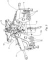
- the harrow 1 comprises a frame or central frame 2 which carries flanges 10 which are capable of configuring a three-point attachment for a hydraulic lift of an agricultural tractor and two lateral frames 3, 4 which are articulated to the central frame about respective hinges 5 and which can be pivoted between an operative position (illustrated in Figure 1 ), in which the lateral frames are lowered with a substantially coplanar arrangement, and a transport position, in which they are raised with an arrangement which is preferably mutually parallel with a minimal transverse spatial requirement of the machine 1.
- a plurality of rotors with relevant implements 6 is mounted on each of the lateral frames 3 and 4.
- those rotors are motorized by means of respective secondary gearboxes 7 which are provided with movement output axes 23.
- the secondary gearboxes 7 in turn draw movement from a primary or central gearbox 8 which is mounted on a support 15 of the central frame 2.
- connection between the gearboxes 7, 8 and between the central gearbox 8 and the power take-off of an agricultural tractor is preferably brought about by means of universal joint shafts 9.
- fluid-dynamic cylinders 11 between the central frame 2 and the respective lateral frames 3, 4.
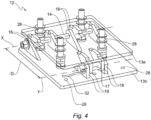
- this torque meter 12 comprises a pair of upper and lower plates 13a, 13b, respectively, of which one is secured to the gearbox 8 and the other is secured to the frame 2.
- the two plates 13a, 13b are preferably secured to each other with hinge type constraints 14, 17.
- the two plates 13a, 13b are hinged by means of a hinge pin 14 which extends through holes which are provided in pairs of flanges 16.
- the plates 13a, 13b can advantageously be connected to each other at the side opposite the pin 14 by means of a load cell 17 with a pin which extends into respective coaxial holes of second flanges 18 and which blocks the raising of the plates 13a, 13b.
- the shear beam cells are used to measure the loads applied to pulleys, hoists, cranes and weighing installations which may be integrated in overhead cranes.
- the axes X and Y of the pins 14 and 17, respectively, are parallel and spaced apart (cf., for example, the spacing D in Figure 4 ) so that the torque meter 12 carries out an isostatic system when viewed from a plane which is transverse to the axes X, Y mentioned above.
- the axes X and Y are further parallel with the movement input axis 19 into the central gearbox 8 so that the counter-torque generated by the power which is supplied via the gearbox 8 and which is discharged to the central frame 2 passes through the load cell 17.
- this load cell is provided with extensometers (not illustrated) and is therefore capable of measuring the shearing force which extends through it. With this force being known and knowing the geometry of the plates 13a, 13b and the pins 14, 17, therefore, it is readily possible to calculate the torque and the power supplied via the central gearbox 8.
- the axes X and Y can be parallel with at least one of the movement output axes 21 from the central gearbox 8.
- the torque meter 12 can measure the counter-torque between the gearbox 8 and the frame 2 which supports it with reference to a movement output axis 21 from the central gearbox 8.
- the upper plate 13a and lower plate 13b are secured to each other with hinge type constraints 14, 17 in accordance with two axes X, Y which are mutually parallel but which are arranged in such a manner that one of the hinge type constraints includes the load cell 17 and the other of the hinge type constraints is positioned with respect to the corresponding movement output axis 21 so as to minimize the torque generated with respect to the corresponding movement output axis by a force directed in accordance with this axis.
- the other of the hinge type constraints 14 is arranged to identify a hinge axis X which substantially intersects orthogonally with the corresponding movement input or output axis.
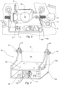
- the torque meter 12 is constructed with such a geometry as to be interchangeable (and therefore, to be able to replace without other adaptations), a spacer 20 (shown in Figure 5 ) which is normally used in conventional foldable harrows in order to space the assembly of the central gearbox 8 on the support 15 of the central frame 2 in order to level and align the movement output axes 21 from the central gearbox 8 with the movement input axes 22 of the secondary gearboxes 7, or to level the universal joint shafts 9 which connect them.
- a spacer 20 shown in Figure 5
- FIG. 5 which is normally used in conventional foldable harrows in order to space the assembly of the central gearbox 8 on the support 15 of the central frame 2 in order to level and align the movement output axes 21 from the central gearbox 8 with the movement input axes 22 of the secondary gearboxes 7, or to level the universal joint shafts 9 which connect them.
- the torque meter 12 of this invention can be constructed in the form of a kit suitable for both the initial equipping of an agricultural machine 1 and potential retrofitting of conventional machines which are normally provided with the spacer 20 for levelling the gearbox 8. In this case, it is simply necessary to replace the spacer 20 with the above-mentioned kit.
- the torque meter 12 comprises means 28 for reversible fixing to the gearbox 8, at one side, and to the frame 2, at the other.
- the fixing means 28 are configured to cooperate with respective fixing counter-means which are provided on the gearbox 8 and on the frame 2.
- the fixing means 28 are defined in the plates 13a, 13b.
- the upper plate 13a and lower plate 13b comprise means for reversible fixing to the gearbox 8 and the frame 2, respectively, or vice versa.
- the fixing means 28 include fixing openings or holes which are defined in the plates 13a, 13b. It may be noted that, preferably, the fixing holes are different from the mutual hinging holes of the plates themselves.
- the fixing counter-means also include fixing openings or holes which are defined in the gearbox 8 and in the frame 2 in positions corresponding to those of the fixing openings or holes of the plates 13a, 13b.
- one or more fixing holes can be provided through each of the plates 13a, 13b.
- the fixing holes may be through-holes or may be blind holes.
- the fixing holes are suitable for receiving bolts or other connection means, preferably of the threaded type, in order to reversibly fix the plates 13a, 13b to the gearbox 8 at one side and to the frame 2 at the other side, respectively, or vice versa.
- the holes for fixing to the frame 2 or the gearbox 8 in the plates 13a, 13b are constructed according to the same masks of the fixing holes of a conventional levelling spacer 20 and the overall thickness is identical so that the replacement can also be carried out by a non-skilled operator.
- the torque meter 21 is inserted in the machine 1 by securing the upper plate 13a to the central gearbox 8 and by securing the lower plate 13b to the support 15 of the central frame 2.
- the torque meter 12 is inserted into the machine 1 in a manner parallel with the direction of the movement input axis 19 in the central gearbox 8.
- the kit can be assembled in line and does not require any calibration, the torque measurement being brought about simply by the geometric parameters thereof.
- it is possible to continuously measure the torque transmitted which in turn allows the measured data to be stored in a mass memory 30 in order to generate a historical archive which can be interrogated. It is thereby possible to cause data from other sensors which are fitted to the machine 1 to converge in the memory 30, for example, temperature sensors of the gearbox 7, 8, the function of which is to provide historical data of the operating temperature of each gearbox/branch and to generate alarms in the event of a predetermined thermal threshold being exceeded.
- At least one roller 24 In the rear portion of the harrow 1, there is preferably provided at least one roller 24, the position of which can be adjusted by means of hydraulic actuators 25 in order to vary the working depth of the implements 6.
- the hydraulic actuators 25 are configured to be blocked by means of blocking valves 26.
- Each roller is preferably provided with a position transducer (not shown) which detects the course of the adjustment hydraulic actuators 25 and consequently detects the working depth of the implements 6.
- Two additional proximity sensors 27 can be provided between the central gearbox 8 and the universal joint shafts 9 which connect the movement outputs thereof to the secondary gearboxes 7. These proximity sensors 27 are used to read the angular position of the lateral universal joint shafts 9 during the closure step of the machine 1, preventing any breakages as a result of jams thereof.
- the historical archive of the mass memory 30 can be interrogated by means of an Isobus terminal or monitor 31 which is part of the command console integrated in the cabin of the tractor or forming part of the above-mentioned kit.
- the kit includes a communication connection 32 by means of a communication protocol (for example, Isobus).
- the Isobus terminal 31 allows integrated control of the information items which are stored in the mass memory 30, using an Isobus protocol, that is to say, using a universal language which allows communication between tractors, software and equipment items.
- the measurements stored in the mass memory can be used to monitor the degree of use of the machine.
- the Isobus monitor 31 information items, such as the consumption of power, the working depth, or different alarms. It is possible with the storage and integrated control of the information items also to control the maintenance activities of the harrow 1, and in particular the possible extension of a warranty because the data relating to malfunctions and overloads which are not adequately controlled by the operator will be detected and stored.
- the invention thereby solves the problem set out by achieving a number of advantages, including:
Landscapes
- Life Sciences & Earth Sciences (AREA)
- Engineering & Computer Science (AREA)
- Mechanical Engineering (AREA)
- Soil Sciences (AREA)
- Environmental Sciences (AREA)
- Zoology (AREA)
- Power Engineering (AREA)
- Agricultural Machines (AREA)
Claims (15)
- Landwirtschaftliche Maschine (1) mit einem Rahmen (2), der eingerichtet ist, um ein landwirtschaftliches Arbeitsgerät und ein im Rahmen (2) abgestütztes Getriebe (8) zu verbinden, und zumindest eine Bewegungseingangsachse (19) und zumindest eine Bewegungsausgangsachse (21) aufweist, dadurch gekennzeichnet, dass zwischen dem Getriebe (8) und dem Rahmen (2) ein Drehmomentmesser (12) angeordnet ist, der angeordnet ist, um das Gegendrehmoment zwischen dem Getriebe (8) und dem Rahmen (2), der es abstützt, in Bezug auf die Bewegungseingangsachse (19) oder die Bewegungsausgangsachse (21) zumindest in einem Betriebszustand der landwirtschaftlichen Maschine (1) zu messen.
- Landwirtschaftliche Maschine (1) nach Anspruch 1, wobei der Drehmomentmesser (12) eine Kraftmesszelle (17) umfasst, die zwischen dem Getriebe (8) und dem Rahmen (2) angeordnet ist.
- Landwirtschaftliche Maschine (1) nach Anspruch 1 oder 2, wobei der Drehmomentmesser (12) eine Kraftmesszelle (17) vom elektronischen und/oder hydraulischen Typ umfasst.
- Landwirtschaftliche Maschine (1) nach einem der vorhergehenden Ansprüche, wobei der Drehmomentmesser (12) eine Kraftmesszelle (17) vom Scherbalken- oder Knopftyp umfasst und/oder der Drehmomentmesser (12) zumindest im Messzustand isostatisch ist.
- Landwirtschaftliche Maschine (1) nach einem der vorhergehenden Ansprüche, wobei der Drehmomentmesser (12) eine obere Platte (13a) und eine untere Platte (13b) aufweist, von denen eine am Getriebe (8) und die andere am Rahmen (2) befestigt ist, wobei die obere Platte (13a) und die untere Platte (13b) mit gelenkartigen Einschränkungen (14, 17) in Übereinstimmung mit zwei Achsen (X, Y) aneinander befestigt sind, die zueinander parallel und im Wesentlichen parallel zur Bewegungseingangsachse (19) oder Bewegungsausgangsachse (21) sind, wobei eine der gelenkartigen Einschränkungen (14, 17) eine Kraftmesszelle (17) umfasst.
- Landwirtschaftliche Maschine (1) nach dem vorhergehenden Anspruch, wobei die andere der gelenkartigen Einschränkungen (14) in Bezug auf die entsprechende Bewegungseingangs- oder -ausgangsachse (19, 21) positioniert ist, um das Drehmoment zu minimieren, das in Bezug auf die entsprechende Bewegungseingangsachse oder -ausgangsachse durch einen entlang dieser Bewegungseingangsachse oder -ausgangsachse gerichteten Schub erzeugt wird.
- Landwirtschaftliche Maschine (1) nach dem vorhergehenden Anspruch, wobei die andere der gelenkartigen Einschränkungen (14) angeordnet ist, um eine Gelenkachse (X) zu identifizieren, die sich im Wesentlichen orthogonal mit der entsprechenden Bewegungseingangsachse oder -ausgangsachse schneidet.
- Landwirtschaftliche Maschine (1) nach einem der Ansprüche 5 bis 7, wobei die Gelenktypeinschränkung, die die Kraftmesszelle (17) umfasst, vom Typ mit einem Scharnierstift ist.
- Landwirtschaftliche Maschine (1) nach einem der Ansprüche 5 bis 8, wobei die obere Platte (13a) und untere Platte (13b) ein System zum Nivellieren des Getriebes (8) auf dem Rahmen (2) bilden.
- Landwirtschaftliche Maschine (1) nach einem der vorhergehenden Ansprüche, wobei zumindest ein Sensor vorgesehen ist, der aus einem Temperatursensor des Getriebes (8) und zumindest einem Rotationssensor einer Bewegungseingangsachse (19, 22) oder einer Bewegungsausgangsachse (21, 23) des Getriebes (8) oder eines Nebengetriebes (7) ausgewählt wird.
- Landwirtschaftliche Maschine (1) nach einem der vorhergehenden Ansprüche, wobei der Rahmen (2) eine Mehrzahl von Arbeitsgeräten (6) abstützt.
- Landwirtschaftliche Maschine (1) nach Anspruch 11, wobei der Rahmen (2) mittig ist und die landwirtschaftliche Maschine (1) zwei seitliche Rahmen (3, 4) aufweist, die gelenkig mit dem zentralen Rahmen verbunden sind, wobei die Arbeitsgeräte (6) an den seitlichen Rahmen (3, 4) abgestützt sind.
- Bausatz für eine landwirtschaftliche Maschine (1) mit einem Drehmomentmesser (12), der eingerichtet ist, um zwischen einem Getriebe (8) der landwirtschaftlichen Maschine (1) und einem Rahmen (2) der landwirtschaftlichen Maschine (1) angeordnet zu werden, wobei der Rahmen zum Anschluss eines landwirtschaftlichen Geräts geeignet ist, wobei der Drehmomentmesser (12) eingerichtet ist, um angeordnet zu werden, um das Gegendrehmoment zwischen dem Getriebe (8) und dem Rahmen (2), der es abstützt, in Bezug auf eine Bewegungseingangsachse (19) in das Getriebe (8) oder eine Bewegungsausgangsachse (21) aus dem Getriebe (8) zumindest in einem Betriebszustand der landwirtschaftlichen Maschine (1) zu messen, wobei der Drehmomentmesser (12) eine obere Platte (13a) und eine untere Platte (13b) mit Mitteln (28) zur reversiblen Befestigung am Getriebe (8) bzw. am Rahmen (2) oder umgekehrt aufweist, wobei die Platten (13a, 13b) nebeneinander liegen, voneinander beabstandet sind und mit gelenkartigen Einschränkungen (14, 17) in Übereinstimmung mit zwei voneinander beabstandeten und parallelen Achsen (X, Y) aneinander befestigt sind, wobei die Achsen (X, Y) der gelenkartigen Einschränkungen im Wesentlichen parallel zur Positionierungsebene von zumindest einer der Platten (13a, 13b) sind, wobei die Achsen (X, Y) eingerichtet sind, um parallel zur Bewegungseingangsachse (19) oder der Bewegungsausgangsachse (21) angeordnet zu sein, wobei eine der gelenkartigen Einschränkungen eine Kraftmesszelle (17) und der Bausatz eine Kommunikationsverbindung (32) mittels eines Kommunikationsprotokolls umfasst.
- Verfahren zur Steuerung einer landwirtschaftlichen Maschine (1), die nach einem oder mehreren der Ansprüche 1 bis 12 konstruiert ist, wobei, wenn sich die landwirtschaftliche Maschine (1) in einem Betriebszustand befindet, der Drehmomentmesser (12) das Gegendrehmoment zwischen dem Getriebe (8) und dem Rahmen (2), der es abstützt, in Bezug auf die Bewegungseingangsachse (19) oder Bewegungsausgangsachse (21) misst.
- Verfahren zur Steuerung einer landwirtschaftlichen Maschine (1) nach Anspruch 14, wobei die vom Drehmomentmesser (12) und gegebenenfalls von dem zumindest einen Sensor durchgeführten Messungen in einem Massenspeicher (30) gespeichert und dazu verwendet werden, auf der Grundlage der Daten selbst die Wartungsarbeiten an der Maschine (1) zu kalibrieren und/oder den Nutzungsgrad der Maschine (1) zu überwachen.
Priority Applications (1)
| Application Number | Priority Date | Filing Date | Title |
|---|---|---|---|
| EP24208225.3A EP4490999A3 (de) | 2020-03-27 | 2021-03-29 | Landwirtschaftliche maschine mit elektronischer steuerung und entsprechendes betriebsverfahren |
Applications Claiming Priority (3)
| Application Number | Priority Date | Filing Date | Title |
|---|---|---|---|
| IT102020000006535A IT202000006535A1 (it) | 2020-03-27 | 2020-03-27 | Macchina agricola a controllo elettronico e relativo metodo operativo |
| IT202000030032 | 2020-12-04 | ||
| PCT/IB2021/052584 WO2021191881A1 (en) | 2020-03-27 | 2021-03-29 | Agricultural machine with electronic control and relevant operating method |
Related Child Applications (1)
| Application Number | Title | Priority Date | Filing Date |
|---|---|---|---|
| EP24208225.3A Division EP4490999A3 (de) | 2020-03-27 | 2021-03-29 | Landwirtschaftliche maschine mit elektronischer steuerung und entsprechendes betriebsverfahren |
Publications (2)
| Publication Number | Publication Date |
|---|---|
| EP4125313A1 EP4125313A1 (de) | 2023-02-08 |
| EP4125313B1 true EP4125313B1 (de) | 2024-10-23 |
Family
ID=75728867
Family Applications (2)
| Application Number | Title | Priority Date | Filing Date |
|---|---|---|---|
| EP21722281.9A Active EP4125313B1 (de) | 2020-03-27 | 2021-03-29 | Landwirtschaftliche maschine mit elektronischer steuerung und entsprechendes betriebsverfahren |
| EP24208225.3A Pending EP4490999A3 (de) | 2020-03-27 | 2021-03-29 | Landwirtschaftliche maschine mit elektronischer steuerung und entsprechendes betriebsverfahren |
Family Applications After (1)
| Application Number | Title | Priority Date | Filing Date |
|---|---|---|---|
| EP24208225.3A Pending EP4490999A3 (de) | 2020-03-27 | 2021-03-29 | Landwirtschaftliche maschine mit elektronischer steuerung und entsprechendes betriebsverfahren |
Country Status (3)
| Country | Link |
|---|---|
| EP (2) | EP4125313B1 (de) |
| CN (1) | CN115361860A (de) |
| WO (1) | WO2021191881A1 (de) |
Citations (1)
| Publication number | Priority date | Publication date | Assignee | Title |
|---|---|---|---|---|
| DE3816828C2 (de) * | 1988-05-18 | 1990-09-27 | Jean Walterscheid Gmbh, 5204 Lohmar, De |
Family Cites Families (11)
| Publication number | Priority date | Publication date | Assignee | Title |
|---|---|---|---|---|
| NL7506058A (nl) * | 1975-05-23 | 1976-11-25 | Lely Nv C Van Der | Grondbewerkingsmachine. |
| US4373590A (en) * | 1980-04-25 | 1983-02-15 | The Eversman Mfg. Company | Tilling apparatus |
| FR2644029A1 (fr) * | 1989-03-08 | 1990-09-14 | Bourgeois Republique Philippe | Dispositif d'attelage pivotant pour outil agricole de grande largeur |
| JP3743736B2 (ja) * | 1997-12-18 | 2006-02-08 | Jfeアドバンテック株式会社 | トルク計 |
| DE19943208C2 (de) * | 1999-09-09 | 2003-06-18 | Walterscheid Gmbh Gkn | Antriebsanordnung mit einer Stellvorrichtung |
| DE102005044374A1 (de) * | 2005-09-16 | 2007-03-22 | Amazonen-Werke H. Dreyer Gmbh & Co. Kg | Antriebsvorrichtung für ein landwirtschaftliches Gerät |
| DE102013011694A1 (de) * | 2013-07-12 | 2015-01-15 | Amazonen-Werke H. Dreyer Gmbh & Co. Kg | Bodenbearbeitungsmaschine |
| CN204495501U (zh) * | 2015-03-10 | 2015-07-22 | 河北联合大学 | 一种装配式并联结构传感器 |
| US20180220574A1 (en) | 2017-02-09 | 2018-08-09 | Cnh Industrial Canada, Ltd. | Gauge wheel and hitch force control |
| CN107421676B (zh) | 2017-07-20 | 2024-03-12 | 沈阳农业大学 | 一种悬挂式空间测力系统 |
| CN108489657B (zh) | 2018-05-24 | 2023-09-01 | 农业部南京农业机械化研究所 | 拖拉机三点悬挂空间动态载荷传感装置及其工作方法 |
-
2021
- 2021-03-29 EP EP21722281.9A patent/EP4125313B1/de active Active
- 2021-03-29 CN CN202180024665.4A patent/CN115361860A/zh active Pending
- 2021-03-29 EP EP24208225.3A patent/EP4490999A3/de active Pending
- 2021-03-29 WO PCT/IB2021/052584 patent/WO2021191881A1/en not_active Ceased
Patent Citations (1)
| Publication number | Priority date | Publication date | Assignee | Title |
|---|---|---|---|---|
| DE3816828C2 (de) * | 1988-05-18 | 1990-09-27 | Jean Walterscheid Gmbh, 5204 Lohmar, De |
Also Published As
| Publication number | Publication date |
|---|---|
| CN115361860A (zh) | 2022-11-18 |
| EP4125313A1 (de) | 2023-02-08 |
| WO2021191881A1 (en) | 2021-09-30 |
| EP4490999A3 (de) | 2025-03-19 |
| EP4490999A2 (de) | 2025-01-15 |
Similar Documents
| Publication | Publication Date | Title |
|---|---|---|
| US4173259A (en) | Rear drive assembly with load sensing | |
| US3557892A (en) | Hitch adapter | |
| EP1889531A1 (de) | Verwendung einer Motordrehmoment-/Geschwindigkeitsmeldung eines CAN-Busses als Lastrückmeldung | |
| SU1286101A3 (ru) | Механизм креплени дл зацеплени землеобрабатывающего оборудовани к т гачу | |
| FI122872B (fi) | Menetelmä punnitusjärjestelmän tarkistuspunnituksessa ja ohjelmistotuote sekä järjestely punnitusjärjestelmän tarkistuspunnituksessa ja materiaalinkäsittelykone | |
| SE518719C2 (sv) | Dragfordon för flygplan och ingrepps- och lyftanordning därför | |
| DE102012021191B4 (de) | Lader | |
| DE102012021192B4 (de) | Lader | |
| EP1407653B1 (de) | Vorrichtung zum Regeln der Position eines Anbaugeräts relativ zu einem Trägerfahrzeug | |
| US5140760A (en) | Arrangement for rotator units | |
| US5163570A (en) | Load sensing device for a boom mounted on a vehicle | |
| EP4490999A2 (de) | Landwirtschaftliche maschine mit elektronischer steuerung und entsprechendes betriebsverfahren | |
| EP3831187B1 (de) | Ausleger-arbeitsgerät, selbstfahrende arbeitsmaschine mit einem solchen ausleger-arbeitsgerät sowie ein verfahren zum detektieren der auf den ausleger einwirkenden belastungen | |
| EP2391874B1 (de) | Flurförderzeug | |
| EP3420787A1 (de) | Verfahren zur steuerung des betriebs eines landwirtschaftlichen systems sowie landwirtschaftliches system | |
| US7721813B2 (en) | Implement/hitch draft control using hitch cylinder pressure as load feedback | |
| EP2104412A1 (de) | Modulare getriebeanordnung für ein landwirtschaftliches oder industrielles nutzfahrzeug | |
| US12595825B2 (en) | Device for monitoring the lubrication condition of a bearing of a track roller of a running gear of a tracked vehicle | |
| US6196328B1 (en) | Position sensor drive arrangement | |
| WO2008065237A1 (en) | Front lifting device for a tractor and method for operating a tractor's front lifting device | |
| DE102017211115A1 (de) | Verfahren und Vorrichtung zur Vermeidung von Überbelastung für eine Arbeitsplattform eines Brückenuntersuchungsfahrzeugs | |
| IT202000006535A1 (it) | Macchina agricola a controllo elettronico e relativo metodo operativo | |
| EP4481207B1 (de) | Schwenkantriebeinheit mit laststeueurung | |
| JPH1028405A (ja) | 農作業機の作業部制御装置 | |
| CN209740056U (zh) | 斗式提升机断链检测装置 |
Legal Events
| Date | Code | Title | Description |
|---|---|---|---|
| STAA | Information on the status of an ep patent application or granted ep patent |
Free format text: STATUS: UNKNOWN |
|
| STAA | Information on the status of an ep patent application or granted ep patent |
Free format text: STATUS: THE INTERNATIONAL PUBLICATION HAS BEEN MADE |
|
| PUAI | Public reference made under article 153(3) epc to a published international application that has entered the european phase |
Free format text: ORIGINAL CODE: 0009012 |
|
| STAA | Information on the status of an ep patent application or granted ep patent |
Free format text: STATUS: REQUEST FOR EXAMINATION WAS MADE |
|
| 17P | Request for examination filed |
Effective date: 20221025 |
|
| AK | Designated contracting states |
Kind code of ref document: A1 Designated state(s): AL AT BE BG CH CY CZ DE DK EE ES FI FR GB GR HR HU IE IS IT LI LT LU LV MC MK MT NL NO PL PT RO RS SE SI SK SM TR |
|
| DAV | Request for validation of the european patent (deleted) | ||
| DAX | Request for extension of the european patent (deleted) | ||
| P01 | Opt-out of the competence of the unified patent court (upc) registered |
Effective date: 20230530 |
|
| GRAP | Despatch of communication of intention to grant a patent |
Free format text: ORIGINAL CODE: EPIDOSNIGR1 |
|
| STAA | Information on the status of an ep patent application or granted ep patent |
Free format text: STATUS: GRANT OF PATENT IS INTENDED |
|
| INTG | Intention to grant announced |
Effective date: 20240517 |
|
| GRAS | Grant fee paid |
Free format text: ORIGINAL CODE: EPIDOSNIGR3 |
|
| GRAA | (expected) grant |
Free format text: ORIGINAL CODE: 0009210 |
|
| STAA | Information on the status of an ep patent application or granted ep patent |
Free format text: STATUS: THE PATENT HAS BEEN GRANTED |
|
| AK | Designated contracting states |
Kind code of ref document: B1 Designated state(s): AL AT BE BG CH CY CZ DE DK EE ES FI FR GB GR HR HU IE IS IT LI LT LU LV MC MK MT NL NO PL PT RO RS SE SI SK SM TR |
|
| REG | Reference to a national code |
Ref country code: GB Ref legal event code: FG4D |
|
| REG | Reference to a national code |
Ref country code: CH Ref legal event code: EP |
|
| REG | Reference to a national code |
Ref country code: DE Ref legal event code: R096 Ref document number: 602021020643 Country of ref document: DE |
|
| REG | Reference to a national code |
Ref country code: IE Ref legal event code: FG4D |
|
| REG | Reference to a national code |
Ref country code: LT Ref legal event code: MG9D |
|
| REG | Reference to a national code |
Ref country code: NL Ref legal event code: MP Effective date: 20241023 |
|
| PG25 | Lapsed in a contracting state [announced via postgrant information from national office to epo] |
Ref country code: NL Free format text: LAPSE BECAUSE OF FAILURE TO SUBMIT A TRANSLATION OF THE DESCRIPTION OR TO PAY THE FEE WITHIN THE PRESCRIBED TIME-LIMIT Effective date: 20241023 |
|
| PG25 | Lapsed in a contracting state [announced via postgrant information from national office to epo] |
Ref country code: NL Free format text: LAPSE BECAUSE OF FAILURE TO SUBMIT A TRANSLATION OF THE DESCRIPTION OR TO PAY THE FEE WITHIN THE PRESCRIBED TIME-LIMIT Effective date: 20241023 |
|
| PG25 | Lapsed in a contracting state [announced via postgrant information from national office to epo] |
Ref country code: IS Free format text: LAPSE BECAUSE OF FAILURE TO SUBMIT A TRANSLATION OF THE DESCRIPTION OR TO PAY THE FEE WITHIN THE PRESCRIBED TIME-LIMIT Effective date: 20250223 Ref country code: HR Free format text: LAPSE BECAUSE OF FAILURE TO SUBMIT A TRANSLATION OF THE DESCRIPTION OR TO PAY THE FEE WITHIN THE PRESCRIBED TIME-LIMIT Effective date: 20241023 Ref country code: PT Free format text: LAPSE BECAUSE OF FAILURE TO SUBMIT A TRANSLATION OF THE DESCRIPTION OR TO PAY THE FEE WITHIN THE PRESCRIBED TIME-LIMIT Effective date: 20250224 |
|
| PG25 | Lapsed in a contracting state [announced via postgrant information from national office to epo] |
Ref country code: FI Free format text: LAPSE BECAUSE OF FAILURE TO SUBMIT A TRANSLATION OF THE DESCRIPTION OR TO PAY THE FEE WITHIN THE PRESCRIBED TIME-LIMIT Effective date: 20241023 |
|
| PG25 | Lapsed in a contracting state [announced via postgrant information from national office to epo] |
Ref country code: BG Free format text: LAPSE BECAUSE OF FAILURE TO SUBMIT A TRANSLATION OF THE DESCRIPTION OR TO PAY THE FEE WITHIN THE PRESCRIBED TIME-LIMIT Effective date: 20241023 |
|
| PG25 | Lapsed in a contracting state [announced via postgrant information from national office to epo] |
Ref country code: ES Free format text: LAPSE BECAUSE OF FAILURE TO SUBMIT A TRANSLATION OF THE DESCRIPTION OR TO PAY THE FEE WITHIN THE PRESCRIBED TIME-LIMIT Effective date: 20241023 |
|
| PG25 | Lapsed in a contracting state [announced via postgrant information from national office to epo] |
Ref country code: NO Free format text: LAPSE BECAUSE OF FAILURE TO SUBMIT A TRANSLATION OF THE DESCRIPTION OR TO PAY THE FEE WITHIN THE PRESCRIBED TIME-LIMIT Effective date: 20250123 |
|
| PG25 | Lapsed in a contracting state [announced via postgrant information from national office to epo] |
Ref country code: LV Free format text: LAPSE BECAUSE OF FAILURE TO SUBMIT A TRANSLATION OF THE DESCRIPTION OR TO PAY THE FEE WITHIN THE PRESCRIBED TIME-LIMIT Effective date: 20241023 Ref country code: GR Free format text: LAPSE BECAUSE OF FAILURE TO SUBMIT A TRANSLATION OF THE DESCRIPTION OR TO PAY THE FEE WITHIN THE PRESCRIBED TIME-LIMIT Effective date: 20250124 |
|
| PG25 | Lapsed in a contracting state [announced via postgrant information from national office to epo] |
Ref country code: PL Free format text: LAPSE BECAUSE OF FAILURE TO SUBMIT A TRANSLATION OF THE DESCRIPTION OR TO PAY THE FEE WITHIN THE PRESCRIBED TIME-LIMIT Effective date: 20241023 |
|
| PG25 | Lapsed in a contracting state [announced via postgrant information from national office to epo] |
Ref country code: RS Free format text: LAPSE BECAUSE OF FAILURE TO SUBMIT A TRANSLATION OF THE DESCRIPTION OR TO PAY THE FEE WITHIN THE PRESCRIBED TIME-LIMIT Effective date: 20250123 |
|
| PG25 | Lapsed in a contracting state [announced via postgrant information from national office to epo] |
Ref country code: SM Free format text: LAPSE BECAUSE OF FAILURE TO SUBMIT A TRANSLATION OF THE DESCRIPTION OR TO PAY THE FEE WITHIN THE PRESCRIBED TIME-LIMIT Effective date: 20241023 |
|
| PG25 | Lapsed in a contracting state [announced via postgrant information from national office to epo] |
Ref country code: DK Free format text: LAPSE BECAUSE OF FAILURE TO SUBMIT A TRANSLATION OF THE DESCRIPTION OR TO PAY THE FEE WITHIN THE PRESCRIBED TIME-LIMIT Effective date: 20241023 |
|
| PG25 | Lapsed in a contracting state [announced via postgrant information from national office to epo] |
Ref country code: EE Free format text: LAPSE BECAUSE OF FAILURE TO SUBMIT A TRANSLATION OF THE DESCRIPTION OR TO PAY THE FEE WITHIN THE PRESCRIBED TIME-LIMIT Effective date: 20241023 |
|
| PG25 | Lapsed in a contracting state [announced via postgrant information from national office to epo] |
Ref country code: RO Free format text: LAPSE BECAUSE OF FAILURE TO SUBMIT A TRANSLATION OF THE DESCRIPTION OR TO PAY THE FEE WITHIN THE PRESCRIBED TIME-LIMIT Effective date: 20241023 |
|
| REG | Reference to a national code |
Ref country code: DE Ref legal event code: R097 Ref document number: 602021020643 Country of ref document: DE |
|
| PG25 | Lapsed in a contracting state [announced via postgrant information from national office to epo] |
Ref country code: SK Free format text: LAPSE BECAUSE OF FAILURE TO SUBMIT A TRANSLATION OF THE DESCRIPTION OR TO PAY THE FEE WITHIN THE PRESCRIBED TIME-LIMIT Effective date: 20241023 |
|
| PG25 | Lapsed in a contracting state [announced via postgrant information from national office to epo] |
Ref country code: CZ Free format text: LAPSE BECAUSE OF FAILURE TO SUBMIT A TRANSLATION OF THE DESCRIPTION OR TO PAY THE FEE WITHIN THE PRESCRIBED TIME-LIMIT Effective date: 20241023 |
|
| PLBE | No opposition filed within time limit |
Free format text: ORIGINAL CODE: 0009261 |
|
| STAA | Information on the status of an ep patent application or granted ep patent |
Free format text: STATUS: NO OPPOSITION FILED WITHIN TIME LIMIT |
|
| PG25 | Lapsed in a contracting state [announced via postgrant information from national office to epo] |
Ref country code: SE Free format text: LAPSE BECAUSE OF FAILURE TO SUBMIT A TRANSLATION OF THE DESCRIPTION OR TO PAY THE FEE WITHIN THE PRESCRIBED TIME-LIMIT Effective date: 20241023 |
|
| 26N | No opposition filed |
Effective date: 20250724 |
|
| PG25 | Lapsed in a contracting state [announced via postgrant information from national office to epo] |
Ref country code: MC Free format text: LAPSE BECAUSE OF FAILURE TO SUBMIT A TRANSLATION OF THE DESCRIPTION OR TO PAY THE FEE WITHIN THE PRESCRIBED TIME-LIMIT Effective date: 20241023 |
|
| REG | Reference to a national code |
Ref country code: CH Ref legal event code: H13 Free format text: ST27 STATUS EVENT CODE: U-0-0-H10-H13 (AS PROVIDED BY THE NATIONAL OFFICE) Effective date: 20251023 |
|
| PG25 | Lapsed in a contracting state [announced via postgrant information from national office to epo] |
Ref country code: LU Free format text: LAPSE BECAUSE OF NON-PAYMENT OF DUE FEES Effective date: 20250329 |
|
| GBPC | Gb: european patent ceased through non-payment of renewal fee |
Effective date: 20250329 |
|
| REG | Reference to a national code |
Ref country code: BE Ref legal event code: MM Effective date: 20250331 |
|
| PG25 | Lapsed in a contracting state [announced via postgrant information from national office to epo] |
Ref country code: GB Free format text: LAPSE BECAUSE OF NON-PAYMENT OF DUE FEES Effective date: 20250329 |
|
| PG25 | Lapsed in a contracting state [announced via postgrant information from national office to epo] |
Ref country code: BE Free format text: LAPSE BECAUSE OF NON-PAYMENT OF DUE FEES Effective date: 20250331 |
|
| PG25 | Lapsed in a contracting state [announced via postgrant information from national office to epo] |
Ref country code: CH Free format text: LAPSE BECAUSE OF NON-PAYMENT OF DUE FEES Effective date: 20250331 |
|
| PG25 | Lapsed in a contracting state [announced via postgrant information from national office to epo] |
Ref country code: IE Free format text: LAPSE BECAUSE OF NON-PAYMENT OF DUE FEES Effective date: 20250329 |
|
| REG | Reference to a national code |
Ref country code: AT Ref legal event code: UEP Ref document number: 1733993 Country of ref document: AT Kind code of ref document: T Effective date: 20241023 |
|
| PGFP | Annual fee paid to national office [announced via postgrant information from national office to epo] |
Ref country code: DE Payment date: 20260319 Year of fee payment: 6 |
|
| PGFP | Annual fee paid to national office [announced via postgrant information from national office to epo] |
Ref country code: AT Payment date: 20260320 Year of fee payment: 6 |
|
| PGFP | Annual fee paid to national office [announced via postgrant information from national office to epo] |
Ref country code: IT Payment date: 20260304 Year of fee payment: 6 |
|
| PGFP | Annual fee paid to national office [announced via postgrant information from national office to epo] |
Ref country code: FR Payment date: 20260323 Year of fee payment: 6 |
|
| PGFP | Annual fee paid to national office [announced via postgrant information from national office to epo] |
Ref country code: TR Payment date: 20260325 Year of fee payment: 6 |
|
| PG25 | Lapsed in a contracting state [announced via postgrant information from national office to epo] |
Ref country code: CY Free format text: LAPSE BECAUSE OF FAILURE TO SUBMIT A TRANSLATION OF THE DESCRIPTION OR TO PAY THE FEE WITHIN THE PRESCRIBED TIME-LIMIT Effective date: 20241023 |
|
| PG25 | Lapsed in a contracting state [announced via postgrant information from national office to epo] |
Ref country code: LT Free format text: LAPSE BECAUSE OF FAILURE TO SUBMIT A TRANSLATION OF THE DESCRIPTION OR TO PAY THE FEE WITHIN THE PRESCRIBED TIME-LIMIT Effective date: 20241023 |