EP4124473A2 - Dynamische reifendruckregelanlage - Google Patents
Dynamische reifendruckregelanlage Download PDFInfo
- Publication number
- EP4124473A2 EP4124473A2 EP22186984.5A EP22186984A EP4124473A2 EP 4124473 A2 EP4124473 A2 EP 4124473A2 EP 22186984 A EP22186984 A EP 22186984A EP 4124473 A2 EP4124473 A2 EP 4124473A2
- Authority
- EP
- European Patent Office
- Prior art keywords
- tire
- pressure
- air
- rim
- displacement device
- Prior art date
- Legal status (The legal status is an assumption and is not a legal conclusion. Google has not performed a legal analysis and makes no representation as to the accuracy of the status listed.)
- Pending
Links
Images






Classifications
-
- B—PERFORMING OPERATIONS; TRANSPORTING
- B60—VEHICLES IN GENERAL
- B60C—VEHICLE TYRES; TYRE INFLATION; TYRE CHANGING; CONNECTING VALVES TO INFLATABLE ELASTIC BODIES IN GENERAL; DEVICES OR ARRANGEMENTS RELATED TO TYRES
- B60C23/00—Devices for measuring, signalling, controlling, or distributing tyre pressure or temperature, specially adapted for mounting on vehicles; Arrangement of tyre inflating devices on vehicles, e.g. of pumps or of tanks; Tyre cooling arrangements
- B60C23/001—Devices for manually or automatically controlling or distributing tyre pressure whilst the vehicle is moving
- B60C23/002—Devices for manually or automatically controlling or distributing tyre pressure whilst the vehicle is moving by monitoring conditions other than tyre pressure or deformation
-
- B—PERFORMING OPERATIONS; TRANSPORTING
- B60—VEHICLES IN GENERAL
- B60C—VEHICLE TYRES; TYRE INFLATION; TYRE CHANGING; CONNECTING VALVES TO INFLATABLE ELASTIC BODIES IN GENERAL; DEVICES OR ARRANGEMENTS RELATED TO TYRES
- B60C19/00—Tyre parts or constructions not otherwise provided for
-
- B—PERFORMING OPERATIONS; TRANSPORTING
- B60—VEHICLES IN GENERAL
- B60C—VEHICLE TYRES; TYRE INFLATION; TYRE CHANGING; CONNECTING VALVES TO INFLATABLE ELASTIC BODIES IN GENERAL; DEVICES OR ARRANGEMENTS RELATED TO TYRES
- B60C23/00—Devices for measuring, signalling, controlling, or distributing tyre pressure or temperature, specially adapted for mounting on vehicles; Arrangement of tyre inflating devices on vehicles, e.g. of pumps or of tanks; Tyre cooling arrangements
- B60C23/001—Devices for manually or automatically controlling or distributing tyre pressure whilst the vehicle is moving
- B60C23/004—Devices for manually or automatically controlling or distributing tyre pressure whilst the vehicle is moving the control being done on the wheel, e.g. using a wheel-mounted reservoir
-
- B—PERFORMING OPERATIONS; TRANSPORTING
- B60—VEHICLES IN GENERAL
- B60C—VEHICLE TYRES; TYRE INFLATION; TYRE CHANGING; CONNECTING VALVES TO INFLATABLE ELASTIC BODIES IN GENERAL; DEVICES OR ARRANGEMENTS RELATED TO TYRES
- B60C23/00—Devices for measuring, signalling, controlling, or distributing tyre pressure or temperature, specially adapted for mounting on vehicles; Arrangement of tyre inflating devices on vehicles, e.g. of pumps or of tanks; Tyre cooling arrangements
- B60C23/02—Signalling devices actuated by tyre pressure
- B60C23/04—Signalling devices actuated by tyre pressure mounted on the wheel or tyre
- B60C23/0408—Signalling devices actuated by tyre pressure mounted on the wheel or tyre transmitting the signals by non-mechanical means from the wheel or tyre to a vehicle body mounted receiver
- B60C23/0422—Signalling devices actuated by tyre pressure mounted on the wheel or tyre transmitting the signals by non-mechanical means from the wheel or tyre to a vehicle body mounted receiver characterised by the type of signal transmission means
- B60C23/0433—Radio signals
- B60C23/0447—Wheel or tyre mounted circuits
- B60C23/0455—Transmission control of wireless signals
-
- B—PERFORMING OPERATIONS; TRANSPORTING
- B60—VEHICLES IN GENERAL
- B60C—VEHICLE TYRES; TYRE INFLATION; TYRE CHANGING; CONNECTING VALVES TO INFLATABLE ELASTIC BODIES IN GENERAL; DEVICES OR ARRANGEMENTS RELATED TO TYRES
- B60C23/00—Devices for measuring, signalling, controlling, or distributing tyre pressure or temperature, specially adapted for mounting on vehicles; Arrangement of tyre inflating devices on vehicles, e.g. of pumps or of tanks; Tyre cooling arrangements
- B60C23/10—Arrangement of tyre-inflating pumps mounted on vehicles
-
- B—PERFORMING OPERATIONS; TRANSPORTING
- B60—VEHICLES IN GENERAL
- B60B—VEHICLE WHEELS; CASTORS; AXLES FOR WHEELS OR CASTORS; INCREASING WHEEL ADHESION
- B60B19/00—Wheels not otherwise provided for or having characteristics specified in one of the subgroups of this group
-
- B—PERFORMING OPERATIONS; TRANSPORTING
- B60—VEHICLES IN GENERAL
- B60C—VEHICLE TYRES; TYRE INFLATION; TYRE CHANGING; CONNECTING VALVES TO INFLATABLE ELASTIC BODIES IN GENERAL; DEVICES OR ARRANGEMENTS RELATED TO TYRES
- B60C5/00—Inflatable pneumatic tyres or inner tubes
-
- B—PERFORMING OPERATIONS; TRANSPORTING
- B60—VEHICLES IN GENERAL
- B60C—VEHICLE TYRES; TYRE INFLATION; TYRE CHANGING; CONNECTING VALVES TO INFLATABLE ELASTIC BODIES IN GENERAL; DEVICES OR ARRANGEMENTS RELATED TO TYRES
- B60C5/00—Inflatable pneumatic tyres or inner tubes
- B60C5/02—Inflatable pneumatic tyres or inner tubes having separate inflatable inserts, e.g. with inner tubes; Means for lubricating, venting, preventing relative movement between tyre and inner tube
Definitions
- This invention relates to tire pressure regulation systems.
- the adherence or friction generated by tires with a road or track surface depends on the pressure with which they are inflated, since this pressure increases or decreases the contact surface with the surface on which these tires are rolling. Grip is a determining factor in vehicle safety and tire wear. It is known that the stopping distance can be cut by as much as 10m if the tires have the optimum pressure. The rate of acceleration of the vehicle can be dramatically increased as well.
- Such systems allow the ability to reduce or increase the air pressure in all tires.
- a limitation of this device is that the air is fed and released through the tire valve, which, because of its limited capacity, results in a system that is sluggish, and which requires significant time to increase or decrease the tire pressure.
- the system is only able to adjust the pressure in all tires and not just selected tires that might have particular need of pressure adjustment.
- What is needed is a system and method which, during driving, dynamically, essentially instantaneously depending on the momentary need, and optionally individually adjusts air pressure in the tire or tires of a vehicle.
- a dynamic tire pressure adjusting system adaptable to the after-market use.
- a system and method/apparatus are provided which dynamically and optionally automatically and individually adjust air pressure in the tire or tires of a vehicle.
- the system is adapted for use with at least one tire mounted on a rim.
- the tire has an internal volume inflated with air.
- the rim is made up of two nested portions adapted such that relative rotation of the nested portions from a neutral position in which tire pressure is at a highest level causes a mechanism in the system to increase the volume inside the tire so as to reduce the tire pressure, thereby increasing grip.
- Such a system depicted in Figures 2 to 12C is adapted to after-market applications.
- the invention adjusts tire pressure quickly and dynamically, depending on braking or acceleration forces acting on the vehicle, and optionally, based on the terrain and the particular road or track conditions to which the vehicle is subjected.
- the invention makes it possible to automatically, dynamically and essentially instantaneously adjust tire pressure, depending on torque applied to the wheels and/or the conditions of travel and use of the vehicle equipped with it.
- the invention in some embodiments, has very little impact as possible on existing driving systems and is retrofittable to existing vehicles.
- An object of the invention is to augment safety by increasing or decreasing friction between the tire(s) and the road or track surfaces. Braking distance, when combined with an ABS system, can be significantly reduced with the invention.
- Another object of the invention is increase vehicle performance by providing friction conditions adapted to the forces acting on the vehicle while driving, which as in curves.
- Still another object of the invention is the control of the footprint of a tire and the pressure distribution on the tire across its width, which, if controlled properly, can reduce wear between the edges and the middle of the tire road contact surface. This can extend the life of the tire.
- FIG. 8A Onwards, with a particularly interesting embodiment shown in FIG. 13A .
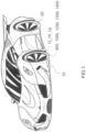
- the DPR System 12 includes at least one displacement device 14 mounted in a wheel rim housing 16, which together act as the wheel rim 20 of the vehicle 10. Note that different variants of the above are shown by adding primes after the number or by following the reference number with a letter. Having the same base reference number indicates that the element referred to is a substitute for other elements marked with the same base reference number.
- a control device 30 for actuating the displacement device uses sensed parameters sensed by sensors s1, s2, s3, s4, and s5, optionally applying Al/deep learning algorithms 32, to configure and send command signals i/o to the system 12 of the invention so as to adjust a footprint 34 (not shown) of the tire 22 to suit the driving conditions or to adjust pressure to an acceptable range.
- the displacement device 16, 16', 16", 16'" includes an actuator 36, 36', 36" which can be mechanical (thread, piston rod, or cam operated), electro-mechanical, electro-magnetic, and optionally a wireless data transmitter 40 activated by wireless signals.
- the displacement device 16 is a telescoping rim 24a, 24b and, in this case, the displacement surface or surfaces 26' are the portions of the rim 24 against which the tire mounts. In this embodiment, the displacement device is simplified.
- the system 12 includes interlocking, expandable and contractable two part wheel rim components 24a, 24b on which a tire 22 preferably enclosing an inner tube 42, a wheel rim actuation device 44 (which moves the wheel rim components toward and away from each other according to a command from the control device 30), momentum sensors S3 (which sense momentum changes at braking, acceleration or in curves), data interfaces 46 between the sensors s1, S2, S3, s4, s5 and the control device 30 (which reads incoming data and sends signals to activate the rim activation device 44 so as to adjust the pressure of each tire 22 based on either AI algorithms, deep learning or the use of a lookup table or graphical methods.
- a wheel rim actuation device 44 which moves the wheel rim components toward and away from each other according to a command from the control device 30
- momentum sensors S3 which sense momentum changes at braking, acceleration or in curves
- data interfaces 46 between the sensors s1, S2, S3, s4, s5 and the control device
- the tire 22 encloses an inner tube 42.
- a tire deformation ring 15 has a displacement surface (26 for example) which presses against the sidewall (for example) of the tire 20 when actuated.
- the displacement device 16' (for example) is separate from an essentially standard rim 24' (for example), the surface acting on either the sidewalls or the tread, preferably opposite to the tire road engagement surface or footprint of the tire.
- the displacement device 16' includes a tire deformation ring 15 actuated by actuators (36, 36'. 36") attached to inwardly directed ears 17 thereof.
- the displacement surface 26' is formed on the ring 15 and is smoothly convex extending from the ring so as to enable the ring to adequately deform the sidewall of the tire 20, in order to change its pressure in a manner that meaningfully changes the tire's footprint on the road surface.
- the above embodiments have the distinct advantage that the tire pressure can be adjusted without continually and cyclically deforming the tire with each tire revolution, thereby avoiding unnecessary heat generation and hysteresis effects on the rubber.
- a simple adjustment can permanently adjust the pressure for mountain driving or straight-away highway driving.
- the actuation device 36 (variant 1) uses an electro-magnet to actuate the displacement device 16'.
- a metal loop 52 retains the displacement device 16' in place (so it doesn't simply fall off) yet allowing it to move laterally in a working range.
- the alternate actuation device 36' is a thread system operated by a gear motor 50.
- the second alternate actuation device 36" uses a gear motor 50' to draw up a cable 54 attached to the displacement device 16'.
- cams or other devices can also be used to actuate the various components.
- the displacement device 16" is a sphere 56 free to rotate on ball bearings contained in a spherical ball bearing holder 58 which actuates the sphere against and away from the tire by way of a linkage mechanism 60.
- This sphere 56 is preferably located above the tire at a location that allows actuation against the tire throughout the range of swing of the tire during turning.
- a disadvantage of this embodiment is that energy is required to deform the tire during normal driving conditions in which grip is not such much a safety factor. However, it is nevertheless advantageous where the driving conditions include many curves and where maximum speed cannot be attained.
- the air pressure in the tires could be separately topped off.
- the displacement device 16′′′ includes a cylindrical roller 62 attached to a lever connected to a frame 62 which moves with the wheel as the wheels turns left or right at the action of a steering wheel (advantageously, the cylinder is easier to suspend in a low friction manner and is simpler to construct than a spherical variant), wherein to control tire pressure, the roller 62 is controlled to press against the tire 20 and to release pressing against the tire. It too is supported by a linkage mechanism 60' that allows the cylinder to be actuated against the tire and released.
- a disadvantage is that energy is required to deform the tire during normal driving conditions in which grip is not such much a safety factor. However, it is nevertheless advantageous where the driving conditions include many curves and where maximum speed cannot be attained.
- the displacement device 16"" includes two rollers 62' attached to levers 63' connected to a frame 65' which moves with the wheel as the wheels turns left or right at the action of a steering wheel, wherein to control tire pressure, the rollers 62' are controlled to press against the tire 20 , for example, against the sidewalls and to release pressing against the tire. It too is supported by a linkage mechanism 63' that allows the rollers to be actuated against the tire and released.
- a disadvantage is that energy is required to deform the tire during normal driving conditions in which grip is not such much a safety factor.
- FIGs 5-7 tend to heat the tire as the rubber deforms. Such heat further improves the grip of the tire and so is not detrimental.
- Such increased grip is advantageous where the driving conditions include many curves and where maximum speed cannot be attained.
- a tire pressure regulation system including a mechanical means for controlling the volume of air within a tire activated by torque applied when accelerating or stopping
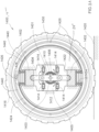
- an alternate embodiment 1400 needs no air pump and no valve, and in fact, no active controller, but which wheel is made up of two nested portions 1401 and 1403 having bearing(s) 1405 or the like mounted therebetween, which are free to move a limited distance with respect to one another.
- This embodiment 1400 uses at least one piston 1402 (preferably at least two or more evenly spaced about the center of the wheel, quite easily four pistons) each optionally connected to a piston rod 1404 which is in turn connected to a crank 1406 (connected to the rotating axel) which rotates about the center 1410 of the wheel 1412.
- piston rod is optional because the actuation of the pistons of all embodiments using pistons in the instant application can be effectuated by actuators which are optionally controlled by a controller to suit the road conditions (wet, muddy, icy, acceleration, stopping, sharp turns, hot temperatures, etc.).
- actuators which are optionally controlled by a controller to suit the road conditions (wet, muddy, icy, acceleration, stopping, sharp turns, hot temperatures, etc.).
- Optional springs 1414 preferably with dampers, tend to maintain an equilibrium position in which the piston 1402 is at a high position in which the tire pressure is at a high point of Ph.
- An optional inner tube or liner 1440 can be integral with the accordion diaphragm 1424 or separate therefrom. Where the accordion diaphragm 1424 is sealed to a corresponding opening in the wheel 1405 (see FIG.
- an inner tube is completely optional but desirable to provide further assurance of no leakage.
- inner tube walls 1440 may contain any fluid, including a liquid (in which case a hydraulic system is provided).
- a liquid in which case a hydraulic system is provided.
- the time required for the rim to turn relative to the axle so as to drawn down the piston or other internal volume altering mechanism typically can be accomplished in the time required for the rim or wheel to turn a quarter turn relative to the axle at any given speed.
- the approximate time can easily be calculated and varies depending on the speed of the wheel, the faster the wheel is turning, the quicker the one quarter turn is accomplished. For example, for a speed of 50km/hr, and a tire of the size where 1 ⁇ 4 of its circumference is approx. 0.5m, then the time to activate the device to effectively reduce tire pressure is 0.036 seconds, or 36 milliseconds.
- the volume difference is just 10 liters.
- the system can at least reduce tire pressure essentially instantaneously by 10%. It can be imagined, however that 20% could be achieved using the principles taught in the instant application. Consequently, the invention can adjust the pressure of a tire during operation by 10%.
- a tire filled at 35psi therefore can have its pressure essentially instantaneously varied between 35psi and 31.5psi, which results in a substantial increase in grip.
- the device of the invention can potentially reduce stopping distance by about one third of 20%, or by about 7%. Acceleration and deceleration are improved by about 9%.
- the typical braking distance for a car at 50mph is 38m, not including the time to react.
- Stopping distances at different speeds Speed Thinking + braking distance Stopping distance 20mph 6m + 6m 12m (40 feet) 30mph 9m + 14m 23m (75 feet) 40mph 12m + 24m 36m (118 feet) 50mph 15m + 38m 53m (174 feet) 60mph 18m + 55m 73m (240 feet) 70mph 21m + 75m 96m (315 feet) Consequently, at 70mph, the device of the invention can reduce stopping distance by around 2.6 meters. As for acceleration, the device of the invention should improve acceleration over a distance of acceleration of 75m by almost 6.7m.
- a regular inner tube known in the art, can be used.
- a modified inner tube 1422 having at least one accordion portion 1424 better ensures the reliable, long-term functioning of the system of the invention.
- an embodiment essentially identical to the above adaptable to fulfil an after-market rim niche uses a solid piston 1802 that enters into the inside volume of the tire, preferably sealed via a standard inner tube 1625, provided one to one volumetric displacement of the air inside the tire, thereby rapidly adjusting pressure within adverse effects caused by the use of a compressible gas.
- an expansion ring may be disposed in an alternate embodiment, which could be shown inn the drawing as a thin ring whose ends overlap and which is disposed along the radially inner surface of the wheel, with the center of the expansion ring being at the center of the tire.
- the expansion ring is of an overlapping spiral form and is made of flexible spring material, whose overall diameter decreases as the pistons are withdrawn, thereby allowing a radially inward floor (the out expansion ring surface) supporting the inner tube to retract and so increase the volume inside the tire.
- the shape instead of conforming to the inside of the wheel and piston profile, would be more round than the inner tube 1625 (which is shown in FIG. 9 without the support of the expansion ring) and so support the inner tube to conform to a more rounded shape.
- the expansion ring would be formed to be a rolled, expansion leaf spring of a ring form, which would expand based on the action of the pistons, and contract to its more at rest, relaxed position when the pistons are withdrawn, into an annular recess matching the width of the expansion ring and which extends along the entire inner circumference of the rim.
- the result of using this alternate embodiment is that the inner tube 1625 would be subjected to less stress concentrations and therefore be more robust, enjoying a longer life expectancy.
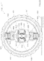
- an embodiment 1600 adaptable to fulfil an after-market rim niche which uses a modified piston system includes typically at least two (for balance) but optionally three or more tilting, nested cylinders 1602 enclosing an accordion diaphragm 1604.
- the nested cylinders 1602 optionally are made of transparent material so as to reveal the inner mechanism.
- this embodiment 1600 needs no air pump and no valve, and in fact, no active controller, but which wheel is made up of two nested portions 1603 and 1605 between which bearing(s) 1401 are mounted, which are free to rotate a limited angle with respect to one another.
- this embodiment 1600 uses at least one pair of nested cylinders 1602 (preferably at least two or more evenly spaced about the center of the wheel, quite easily four pistons) each connected to a piston rod 1606 which is in turn connected to the rotating axel, typically via the lugs 1618, which rotates about the center 1610 of the wheel 1612.
- Springs 1614 preferably with dampers 1616, seek to maintain an equilibrium position in which the pair 1602 of nested cylinders is at a high position in which the tire pressure is at a high point of Ph. Note that thought has been given to provide slotted openings 1617 that allow access to the lugs 1618.
- the axel and inner portion 1603 apply torque to the outer portion 1605 of the wheel 1612 through the dampened crank 1606, braking or accelerating causes a torque build-up which in turn causes the nested cylinders 1602 to retract with one end moving toward the center of the wheel (and eventually applying torque directly through the wheel to the ground as the surface A reaches the stop surface B), thereby reducing tire pressure and consequently, increasing the footprint of the tire 1616 on the road surface 1420.
- the accordion diaphragm 1604 is completely open to the inside of the tire, as shown in FIG. 8A and 8B , air is quickly removed from within the tire which deflation of the tire significantly increases grip, which has the result of reducing stopping distance or increasing rate of acceleration.
- the larger the tube or channel 1620 the quicker the transfer of fluid from within the tire to the accordion diaphragm 1604 and vice versa.
- the fluid can be a liquid.
- FIG. 11 an embodiment is shown which is adaptable to fulfil an after-market rim niche.
- dashed lines show the outline of a structure shown more clearly in FIGs 12A and 12B , which is essentially the same optional cavity 1424 shown in FIGs. 8A , 11 and 12A and 12B , this cavity having a wall 1430 being open-to-the-inside-of-the-tire via openings 1426.
- This embodiment is particularly adapted to a hydraulic system in which an essentially incompressible liquid is moved to and from, via the accordion diaphragm 1604 into and out of an inner tube 1640 disposed in a cavity 1424, 1824 open to the interior of the tire 22.
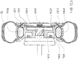
- FIGs. 12A and 12B are cross-sectional views of a further embodiment 1900 of the invention adaptable to fulfil an after-market rim niche.
- This embodiment 1900 is essentially the same as that shown in 8A , 8B , 9 to 11 as to the filling of an inner tube 1440, in the cavity 1640, except that the piston-like devices 1402, 1424, 1602, of filling the inner tube has been replaced with a large central diaphragm 1910 which is moved by a plate 1912 connected to a plunger 1914.
- the diaphragm 1910 is sealed against a manifold 1911, thereby defining a fluid chamber 1922.
- the manifold 1911 has fluid passageways /tubes 1931 formed therein that permit fluid communication of the fluid chamber 1922 with the tube 1640 (not specifically drawn) in the cavity 1424 between the broken lines, the cavity having openings 1426 into the inner volume of the tire 22.
- the plunger 1914 is actuatable along the axis of the wheel, to the right and/or the left, and which can optionally be assisted by a spring 1920 optionally located within the fluid chamber 1922.
- the plunger 1914 optionally is cammed with cam slits 1924 by which a cam follower 1926 is constrained. Relative movement of an inner portion 1903 of the wheel to the outer portion 1905 causes the plunger 1914 to move axially to move the plate 1912 and diaphragm 1910 to pump the fluid 1913 into and out of the inner tube 1640.
- the pistons may be activated by a controller based on inputs from sensors (e.g., the centripetal force sensors or accelerometers).
- sensors e.g., the centripetal force sensors or accelerometers.
- the pistons can be activated automatically and purely mechanically, at the time of need.
- FIG. 8A which opens up into the inside of the wheel can also be separated and connected with a filling tube 1620 as shown in FIGs. 10 and 11 .
- the tube size (also of tube 1931) is preferably of a large diameter to accelerate fluid transfer and therefore improve reaction time.
- the dynamic tire pressure regulation system 12' for a vehicle 10 which regulates tire pressure by pumping air into and releasing air from within the tire includes an air pressure reservoir 70, the control device 30, at least one valve 72 in a custom rim 24", and a second valve 74 (which may be located anywhere on the vehicle).
- the air pressure reservoir 70 is optionally affixed to the vehicle 10, the reservoir being connected via pressure tubes or hoses 76 through the wheel axel 78 and optionally, a rotary pneumatic connection 79.
- the valve 72 is in the form of a cylindrical tube having O-rings 80 disposed in O-ring recesses 82. On one end 84, the valve 72 is connected to an air tube 76 which ultimately connects to the second valve 74.
- the control device 30 selectively turns on and off the valves 72 and 74 allows for the filling and deflating of the tire 20.
- the custom rim 24" includes air exhaust ports 86 and air inlet ports 88.
- the valve 72 is moved back and forth by, for example, a cam 90 (or another suitable actuator).
- the movement of the valve 72 (for example, by cam 90), to the left, seals a front end of the valve against a first O-ring 80 and, upon opening of the second valve 74, allows filing of the tire while a third type of O-ring 80" prevents leakage of air through the exhaust ports 86. Movement of the valve 72 to the right, such that the end 72' passes the exhaust port 86 allows for the tire 20 to deflate.
- the control device 30 reads the pressure sensor s2 inputs to open and closes valves 72 and 74 in order to ensure that the tire quickly (in a matter of milliseconds) reaches the desired pressure, thereby providing a more optimal tire footprint for stopping, accelerating or taking a curve or for the road conditions (wet or dry, icy, muddy or challenging off-road conditions).
- the valve 72 has an air communication capacity much larger than a regular air ventil in a tire stem, thereby allowing pressure in the tire to be adjusted dynamically, quickly, at the command of the control device thus enabling the invention to adapt to the road and/or driving conditions (wet, muddy or icy road, cornering, stopping or accelerating).
- the pressure reservoir 70 is affixed to a rim of the vehicle and so is dedicated to supplying air to the rim and tire combination to which it is affixed.
- the tire 20 includes an inner tube 42, thereby providing a minimum air pressure level in the tire, the system 12' increasing the pressure in the tire by pumping air between the inner tube and the inner wall of the tire or the rim.
- the reservoir 70 includes an electric air pump 92 to ensure that the reservoir has adequate pressure to operate the system 12' of the invention.
- the invention optionally includes a pressure sensor s1, s2 for sensing the pressure in the tire and data communication lines for connecting to the control device and for transmitting at least pressure data to the control device, and for receiving a control signal from the control device.
- a pressure sensor s1, s2 for sensing the pressure in the tire and data communication lines for connecting to the control device and for transmitting at least pressure data to the control device, and for receiving a control signal from the control device.
- the control device 30 need not require inputs such as pressure, force or distance, but instead, merely transmits signals which cause the displacement device 16, 16'. 16", 16′′′ to move to known positions and optionally to stop or begin actuation based on local conditions for pressure, force or distance, thereby eliminating any need for a data transmitter.
- the system 12, 12' of the invention optionally includes momentum sensors s3 that sense centripetal forces or inertial forces, which sensed data is transmitted to the control device for a determination of how to activate the system of the invention.
- the system 12, 12' of the invention optionally includes a distance or location sensor s4 for sensing the distance travelled by an element of the displacement device or a location reached, which distance travelled or location reached can be correlated with tire air pressure or the tire footprint size, further including data communication lines for connecting to the control device and for transmitting at least distance data, and for receiving a control signal.
- a distance or location sensor s4 for sensing the distance travelled by an element of the displacement device or a location reached, which distance travelled or location reached can be correlated with tire air pressure or the tire footprint size, further including data communication lines for connecting to the control device and for transmitting at least distance data, and for receiving a control signal.
- the system 12, 12' of the invention optionally includes a force sensor s5 for sensing the force applied to the tire by the displacement surface and further includes data communication lines for connecting to the control device and for transmitting at least force data, and for receiving a control signal.
- any change in diameter of the tire due to the deformation thereof is considered to re-calibrate the speedometer in order to provide accurate speed information.
- the invention may also a system for maintaining the pressure in a tire within a range specified by a controller programmed at the factory or programmable by the user.
- a reservoir 902 is located within the wheel 904.
- a pressure sensor 906 senses the pressure in the tire and when the pressure is too high, a controller 910 opens a valve 912 to eject air either into the environment or, if the pressure in the reservoir is lower than in the tire, into the reservoir. If the pressure in the reservoir is lower than in the specified range, the driver can be warned of the need to fill up the reservoir, in which case, no pump 914 is needed (See FIG. 19 ).
- the pendulum 916 is rotatably suspended on the outside face of the wheel and, by virtue of the fact that the wheel turns and the pendulum, which is weighted generally doesn't turn with the wheel, the pump 914 is activated.
- the pendulum 916 is connected to the pump 914 and suspended on low friction bearings 922.
- the pendulum 916 can be in the form of a clock pendulum (as also found in an automatic watch movement), or a flywheel which oscillates between two positions, dampened by a spring (typically a spiral spring, as more typically found in an automatic watch pendulum).
- a hubcap 924 can also be used to cover the pendulum and prevent it from being visible from the outside of the vehicle. Although some users will want the pendulum to not be visible from the outside of the vehicle (as in the next embodiment), many will find that the pendulum being visible is a symbol of the advanced technology the user has at his disposal on the vehicle.
- the pendulum 1002 is rotatably suspended on bearings 1022 on the inside face 1004, not visible from the outside of the vehicle and, by virtue of the fact that the wheel turns and the pendulum, which is weighted generally doesn't turn with the wheel, the pump is activated.
- the pendulum can, in all embodiments, include a spring that limits the rotation thereof and promotes a back-and-forth oscillation like a clock pendulum or an automatic watch pendulum.
- the pendulum 916, 1002 activates an electric generator 1102 which charges a battery 1104 in the wheel, which is available to activate an electric pump 1106 on demand of the user or a controller or both.
- the pump 1106 pumps up the reservoir 902 as needed or desired.
- the battery 1104 could serve as the weight at the outer extremity of the pendulum.
- FIG. 18 an embodiment 1200 which regulates tire pressure by pumping air into and releasing air from within the tire is shown where no pendulum is needed. but instead, a mechanical pump 1202, located on the inside face 1204 of the wheel 1206, is activated by bearing against a race 1210 on the axle housing 1212 of the vehicle. The pump 1202 is activated when an engagement mechanism engages the pump with the race 1210 or with a drive train connected to the race.
- a mechanical pump 1202 located on the inside face 1204 of the wheel 1206, is activated by bearing against a race 1210 on the axle housing 1212 of the vehicle.
- the pump 1202 is activated when an engagement mechanism engages the pump with the race 1210 or with a drive train connected to the race.
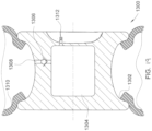
- the wheel 1302 simply contains a high-pressure air reservoir 1304 having a mechanical one way or two-way valve 1306 set in a channel 1308 connecting the reservoir to the inside of the tire, the one-way valve releasing pressure into the tire 1310 through the channel 1308, when the pressure in the tire drops below a certain set level.
- a one-way valve this can be accomplished using a spring of a spring constant that will yield.
- the mechanical valve can be replaced with a pressure sensor positioned to sense the pressure in the tire, which then activates (when the pressure in the tire drops below a desired minimum and/or closes the valve when it exceeds a maximum), mechanically or electrically, a valve that allows air from the reservoir, when its pressure is greater than that inside the tire, to enter the tire and so increase its pressure within a desired range.
- the reservoir 1304 would have a standard air valve 1312 exposed to enable the user to replenish the air in the high-pressure reservoir 1304.
- the invention includes the following features sets:
- the invention augments safety by increasing or decreasing friction between the tire(s) and the road or track surfaces. Braking distance, when combined with an ABS system, can be significantly reduced with the invention.
- the invention increases vehicle performance by providing friction conditions adapted to the forces acting on the vehicle while driving, which as in curves.
- the invention controls the footprint of a tire and the pressure distribution on the tire across its width, which, if controlled properly, reduces wear between the edges and the middle of the tire road contact surface. This can extend the life of the tire.
- the network may include any system for exchanging data, such as, for example, the Internet, an intranet, an extranet, WAN, LAN, wireless network, satellite communications, and/or the like. It is noted that the network may be implemented as other types of networks, such as an interactive television network. The users may interact with the system via any input device such as a keyboard, mouse, kiosk, personal digital assistant, handheld computer, cellular phone and/or the like. Moreover, the system contemplates the use, sale and/or distribution of any goods, services or information having similar functionality described herein.
- the present invention may be embodied as a system, a device, or a method.
- block diagram illustrations support combinations of means for performing the specified functions, combinations of steps for performing the specified functions, and program instruction means for performing the specified functions.
- Each functional block of the block diagrams and flowchart illustrations, and combinations of functional blocks in the block diagrams may be implemented by either special purpose hardware-based computer systems which perform the specified functions or steps, or suitable combinations thereof.
- system contemplates the use, sale and/or distribution of any goods, services or information having similar functionality described herein.
- the terms "comprises”, “comprising”, or variations thereof, are intended to refer to a non-exclusive listing of elements, such that any apparatus, process, method, article, or composition of the invention that comprises a list of elements, that does not include only those elements recited, but may also include other elements such as those described in the instant specification. Unless otherwise explicitly stated, the use of the term “consisting” or “consisting of” or “consisting essentially of' is not intended to limit the scope of the invention to the enumerated elements named thereafter, unless otherwise indicated. Other combinations and/or modifications of the above-described elements, materials or structures used in the practice of the present invention may be varied or adapted by the skilled artisan to other designs without departing from the general principles of the invention.
Landscapes
- Engineering & Computer Science (AREA)
- Mechanical Engineering (AREA)
- Computer Networks & Wireless Communication (AREA)
- Tires In General (AREA)
Applications Claiming Priority (3)
| Application Number | Priority Date | Filing Date | Title |
|---|---|---|---|
| US202163226326P | 2021-07-28 | 2021-07-28 | |
| US202263315634P | 2022-03-02 | 2022-03-02 | |
| US202263335260P | 2022-04-27 | 2022-04-27 |
Publications (2)
| Publication Number | Publication Date |
|---|---|
| EP4124473A2 true EP4124473A2 (de) | 2023-02-01 |
| EP4124473A3 EP4124473A3 (de) | 2023-03-01 |
Family
ID=82742973
Family Applications (1)
| Application Number | Title | Priority Date | Filing Date |
|---|---|---|---|
| EP22186984.5A Pending EP4124473A3 (de) | 2021-07-28 | 2022-07-26 | Dynamische reifendruckregelanlage |
Country Status (2)
| Country | Link |
|---|---|
| US (1) | US20230044053A1 (de) |
| EP (1) | EP4124473A3 (de) |
Cited By (1)
| Publication number | Priority date | Publication date | Assignee | Title |
|---|---|---|---|---|
| IT202300028296A1 (it) * | 2023-12-28 | 2025-06-28 | Antonio Slawitz | Ruota per veicoli |
Families Citing this family (3)
| Publication number | Priority date | Publication date | Assignee | Title |
|---|---|---|---|---|
| JP7287365B2 (ja) * | 2020-08-20 | 2023-06-06 | 横浜ゴム株式会社 | 空気圧管理装置、空気圧管理方法、および空気圧管理プログラム |
| US20230373255A1 (en) * | 2021-07-22 | 2023-11-23 | Hyundai Translead | Thermal monitoring of trailers |
| US12447778B2 (en) * | 2023-12-21 | 2025-10-21 | Volvo Car Corporation | System and method for adaptive tire pressure control |
Citations (1)
| Publication number | Priority date | Publication date | Assignee | Title |
|---|---|---|---|---|
| DE202017106135U1 (de) * | 2017-10-10 | 2017-12-08 | Frank Kauffelt | Reifendruck-Regelsystem durch Fliehkraft |
Family Cites Families (21)
| Publication number | Priority date | Publication date | Assignee | Title |
|---|---|---|---|---|
| GB231754A (en) * | 1924-09-20 | 1925-04-09 | Walter George Gould | Improvements in or relating to inner tubes for pneumatic tyres |
| US2751959A (en) * | 1953-06-11 | 1956-06-26 | Fairchild Engine And Aiplane C | Vehicle wheel |
| US2866501A (en) * | 1956-08-20 | 1958-12-30 | Goodyear Tire & Rubber | Apparatus for siping tires |
| US2981305A (en) * | 1958-10-06 | 1961-04-25 | Chrysler Corp | Variable pressure pneumatic vehicle tire |
| US5109905A (en) * | 1977-12-01 | 1992-05-05 | Lambe Donald M | Dual chamber pneumatic tire with the chambers separated by a collapsible partition wall |
| US5865917A (en) * | 1995-08-09 | 1999-02-02 | Loewe; Richard Thomas | Deformation-based tire inflation device |
| US6658936B2 (en) * | 2001-03-08 | 2003-12-09 | Kokusai Keisokuki Kabushiki Kaisha | Apparatus and method for measuring uniformity and/or dynamic balance of tire |
| DE102004029736A1 (de) * | 2004-06-19 | 2006-01-19 | Deere & Company, Moline | Reifendruckeinstellanlage |
| US8365794B2 (en) * | 2005-01-18 | 2013-02-05 | Android Industries Llc | Inflation work station |
| DE112008001428T5 (de) * | 2007-05-21 | 2010-04-29 | Bol, Stephen J., Muskegon | Radfeste Pumpe für sich selbst aufblasende Reifen |
| DE102008024860A1 (de) * | 2008-05-23 | 2009-11-26 | Continental Aktiengesellschaft | Fahrzeugreifen |
| NZ582354A (en) * | 2009-12-24 | 2010-05-28 | Swashpump Technologies Ltd | Non-rotating nutating plate pump with compound spherical bearing |
| US20120221196A1 (en) * | 2011-02-28 | 2012-08-30 | Continental Automotive Systems, Inc. | Active tire controller device |
| FR2983124B1 (fr) * | 2011-11-30 | 2014-01-24 | Peugeot Citroen Automobiles Sa | Dispositif de regulation de la pression de gonflage d'un pneumatique sur une roue de vehicule |
| US20130153082A1 (en) * | 2011-12-14 | 2013-06-20 | International Business Machines Corporation | Variable friction tires |
| GB2522038A (en) * | 2014-01-10 | 2015-07-15 | Caterpillar Inc | Tyre apparatus |
| US9511634B2 (en) * | 2014-10-30 | 2016-12-06 | Elwha Llc | Systems and methods for anticipatory tire pressure control |
| US10315469B2 (en) * | 2016-09-06 | 2019-06-11 | Aktv8 LLC | Tire management system and method |
| US20210061027A1 (en) * | 2017-10-26 | 2021-03-04 | Applied Mechatronic Products | Apparatus and method for vehicular monitoring, analysis, and control |
| US12384207B2 (en) * | 2020-01-24 | 2025-08-12 | Toyota Motor Engineering & Manufacturing North America, Inc. | Central tire inflation system |
| WO2022108603A1 (en) * | 2020-11-23 | 2022-05-27 | Volvo Truck Corporation | System and method for tire contact patch optimization |
-
2022
- 2022-07-26 US US17/873,208 patent/US20230044053A1/en not_active Abandoned
- 2022-07-26 EP EP22186984.5A patent/EP4124473A3/de active Pending
Patent Citations (1)
| Publication number | Priority date | Publication date | Assignee | Title |
|---|---|---|---|---|
| DE202017106135U1 (de) * | 2017-10-10 | 2017-12-08 | Frank Kauffelt | Reifendruck-Regelsystem durch Fliehkraft |
Cited By (1)
| Publication number | Priority date | Publication date | Assignee | Title |
|---|---|---|---|---|
| IT202300028296A1 (it) * | 2023-12-28 | 2025-06-28 | Antonio Slawitz | Ruota per veicoli |
Also Published As
| Publication number | Publication date |
|---|---|
| US20230044053A1 (en) | 2023-02-09 |
| EP4124473A3 (de) | 2023-03-01 |
Similar Documents
| Publication | Publication Date | Title |
|---|---|---|
| US20230044053A1 (en) | Dynamic tire pressure regulation system | |
| US20210300140A1 (en) | Integrated active valve assembly | |
| JP6981969B2 (ja) | 車両ホイールリム上に搭載されるタイヤに流体媒体を供給するための圧縮機ユニット及び車両ホイールリム上に搭載されるタイヤのための加圧媒体供給デバイスを有する車両ホイールリム | |
| JP4458127B2 (ja) | タイヤ空気圧制御装置 | |
| EP2021194B1 (de) | Vorrichtung zur reifengefahreneinschätzung von fahrzeugrädern | |
| EP3307569B1 (de) | Verfahren zur feststellung der radlasten eines fahrzeuges | |
| CN101553387B (zh) | 运动变换传递装置 | |
| JP2008007017A (ja) | タイヤ空気圧制御装置 | |
| JP2018525262A5 (de) | ||
| US20250153519A1 (en) | Dynamic tire pressure regulation system | |
| JP2008143333A (ja) | 操作シミュレータ | |
| JP4239891B2 (ja) | 車両用タイヤ空気圧調整装置 | |
| US7051778B2 (en) | Device and method for generating energy in a rolling wheel | |
| WO2007077754A1 (ja) | タイヤ空気圧生成装置 | |
| JP2007278796A (ja) | 空気流量演算装置 | |
| EP3335913A1 (de) | System und verfahren für eine luftaufrechterhaltungsreifenanordnung | |
| JP4144575B2 (ja) | 車両制御装置 | |
| EP1343642B1 (de) | Verfahren und vorrichtung zur erzeugung von energie während des rollens eines auf einer felge angebrachten reifens | |
| JP5223961B2 (ja) | 操作シミュレータ | |
| JP4636274B2 (ja) | タイヤ空気圧制御装置 | |
| JP2014065327A (ja) | 車高調整装置 | |
| JP4779905B2 (ja) | タイヤ空気圧制御装置 | |
| JP4899642B2 (ja) | タイヤ空気圧制御装置 | |
| CN121822616A (zh) | 一种方向盘轮缘、方向盘、转向系统和车辆 | |
| JP2007290592A (ja) | タイヤ空気圧制御装置 |
Legal Events
| Date | Code | Title | Description |
|---|---|---|---|
| PUAI | Public reference made under article 153(3) epc to a published international application that has entered the european phase |
Free format text: ORIGINAL CODE: 0009012 |
|
| STAA | Information on the status of an ep patent application or granted ep patent |
Free format text: STATUS: THE APPLICATION HAS BEEN PUBLISHED |
|
| PUAL | Search report despatched |
Free format text: ORIGINAL CODE: 0009013 |
|
| AK | Designated contracting states |
Kind code of ref document: A2 Designated state(s): AL AT BE BG CH CY CZ DE DK EE ES FI FR GB GR HR HU IE IS IT LI LT LU LV MC MK MT NL NO PL PT RO RS SE SI SK SM TR |
|
| AK | Designated contracting states |
Kind code of ref document: A3 Designated state(s): AL AT BE BG CH CY CZ DE DK EE ES FI FR GB GR HR HU IE IS IT LI LT LU LV MC MK MT NL NO PL PT RO RS SE SI SK SM TR |
|
| RIC1 | Information provided on ipc code assigned before grant |
Ipc: B60C 5/02 20060101ALN20230124BHEP Ipc: B60C 5/00 20060101ALN20230124BHEP Ipc: B60B 19/00 20060101ALN20230124BHEP Ipc: B60C 23/10 20060101ALI20230124BHEP Ipc: B60C 23/00 20060101AFI20230124BHEP |
|
| P01 | Opt-out of the competence of the unified patent court (upc) registered |
Effective date: 20230524 |
|
| STAA | Information on the status of an ep patent application or granted ep patent |
Free format text: STATUS: REQUEST FOR EXAMINATION WAS MADE |
|
| 17P | Request for examination filed |
Effective date: 20230626 |
|
| RBV | Designated contracting states (corrected) |
Designated state(s): AL AT BE BG CH CY CZ DE DK EE ES FI FR GB GR HR HU IE IS IT LI LT LU LV MC MK MT NL NO PL PT RO RS SE SI SK SM TR |
|
| STAA | Information on the status of an ep patent application or granted ep patent |
Free format text: STATUS: EXAMINATION IS IN PROGRESS |
|
| 17Q | First examination report despatched |
Effective date: 20240326 |