EP4124441B1 - Folienaufwickelsystem, verbund aus einer folienreckanlage und einem solchen folienaufwickelsystem und verwendung eines solchen verbunds zur herstellung von dünnstfilmen und membranen - Google Patents
Folienaufwickelsystem, verbund aus einer folienreckanlage und einem solchen folienaufwickelsystem und verwendung eines solchen verbunds zur herstellung von dünnstfilmen und membranen Download PDFInfo
- Publication number
- EP4124441B1 EP4124441B1 EP22184819.5A EP22184819A EP4124441B1 EP 4124441 B1 EP4124441 B1 EP 4124441B1 EP 22184819 A EP22184819 A EP 22184819A EP 4124441 B1 EP4124441 B1 EP 4124441B1
- Authority
- EP
- European Patent Office
- Prior art keywords
- film
- roller
- winding
- contact roller
- slide
- Prior art date
- Legal status (The legal status is an assumption and is not a legal conclusion. Google has not performed a legal analysis and makes no representation as to the accuracy of the status listed.)
- Active
Links
Images


Classifications
-
- B—PERFORMING OPERATIONS; TRANSPORTING
- B29—WORKING OF PLASTICS; WORKING OF SUBSTANCES IN A PLASTIC STATE IN GENERAL
- B29C—SHAPING OR JOINING OF PLASTICS; SHAPING OF MATERIAL IN A PLASTIC STATE, NOT OTHERWISE PROVIDED FOR; AFTER-TREATMENT OF THE SHAPED PRODUCTS, e.g. REPAIRING
- B29C55/00—Shaping by stretching, e.g. drawing through a die; Apparatus therefor
- B29C55/02—Shaping by stretching, e.g. drawing through a die; Apparatus therefor of plates or sheets
-
- B—PERFORMING OPERATIONS; TRANSPORTING
- B65—CONVEYING; PACKING; STORING; HANDLING THIN OR FILAMENTARY MATERIAL
- B65H—HANDLING THIN OR FILAMENTARY MATERIAL, e.g. SHEETS, WEBS, CABLES
- B65H18/00—Winding webs
- B65H18/08—Web-winding mechanisms
- B65H18/26—Mechanisms for controlling contact pressure on winding-web package, e.g. for regulating the quantity of air between web layers
-
- B—PERFORMING OPERATIONS; TRANSPORTING
- B29—WORKING OF PLASTICS; WORKING OF SUBSTANCES IN A PLASTIC STATE IN GENERAL
- B29C—SHAPING OR JOINING OF PLASTICS; SHAPING OF MATERIAL IN A PLASTIC STATE, NOT OTHERWISE PROVIDED FOR; AFTER-TREATMENT OF THE SHAPED PRODUCTS, e.g. REPAIRING
- B29C37/00—Component parts, details, accessories or auxiliary operations, not covered by group B29C33/00 or B29C35/00
- B29C37/0003—Discharging moulded articles from the mould
-
- B—PERFORMING OPERATIONS; TRANSPORTING
- B29—WORKING OF PLASTICS; WORKING OF SUBSTANCES IN A PLASTIC STATE IN GENERAL
- B29C—SHAPING OR JOINING OF PLASTICS; SHAPING OF MATERIAL IN A PLASTIC STATE, NOT OTHERWISE PROVIDED FOR; AFTER-TREATMENT OF THE SHAPED PRODUCTS, e.g. REPAIRING
- B29C53/00—Shaping by bending, folding, twisting, straightening or flattening; Apparatus therefor
- B29C53/32—Coiling
-
- B—PERFORMING OPERATIONS; TRANSPORTING
- B29—WORKING OF PLASTICS; WORKING OF SUBSTANCES IN A PLASTIC STATE IN GENERAL
- B29C—SHAPING OR JOINING OF PLASTICS; SHAPING OF MATERIAL IN A PLASTIC STATE, NOT OTHERWISE PROVIDED FOR; AFTER-TREATMENT OF THE SHAPED PRODUCTS, e.g. REPAIRING
- B29C55/00—Shaping by stretching, e.g. drawing through a die; Apparatus therefor
- B29C55/02—Shaping by stretching, e.g. drawing through a die; Apparatus therefor of plates or sheets
- B29C55/023—Shaping by stretching, e.g. drawing through a die; Apparatus therefor of plates or sheets using multilayered plates or sheets
-
- B—PERFORMING OPERATIONS; TRANSPORTING
- B29—WORKING OF PLASTICS; WORKING OF SUBSTANCES IN A PLASTIC STATE IN GENERAL
- B29C—SHAPING OR JOINING OF PLASTICS; SHAPING OF MATERIAL IN A PLASTIC STATE, NOT OTHERWISE PROVIDED FOR; AFTER-TREATMENT OF THE SHAPED PRODUCTS, e.g. REPAIRING
- B29C55/00—Shaping by stretching, e.g. drawing through a die; Apparatus therefor
- B29C55/02—Shaping by stretching, e.g. drawing through a die; Apparatus therefor of plates or sheets
- B29C55/10—Shaping by stretching, e.g. drawing through a die; Apparatus therefor of plates or sheets multiaxial
- B29C55/12—Shaping by stretching, e.g. drawing through a die; Apparatus therefor of plates or sheets multiaxial biaxial
-
- B—PERFORMING OPERATIONS; TRANSPORTING
- B29—WORKING OF PLASTICS; WORKING OF SUBSTANCES IN A PLASTIC STATE IN GENERAL
- B29D—PRODUCING PARTICULAR ARTICLES FROM PLASTICS OR FROM SUBSTANCES IN A PLASTIC STATE
- B29D7/00—Producing flat articles, e.g. films or sheets
- B29D7/01—Films or sheets
-
- B—PERFORMING OPERATIONS; TRANSPORTING
- B65—CONVEYING; PACKING; STORING; HANDLING THIN OR FILAMENTARY MATERIAL
- B65H—HANDLING THIN OR FILAMENTARY MATERIAL, e.g. SHEETS, WEBS, CABLES
- B65H19/00—Changing the web roll
- B65H19/22—Changing the web roll in winding mechanisms or in connection with winding operations
- B65H19/2207—Changing the web roll in winding mechanisms or in connection with winding operations the web roll being driven by a winding mechanism of the centre or core drive type
- B65H19/2215—Turret-type with two roll supports
-
- B—PERFORMING OPERATIONS; TRANSPORTING
- B65—CONVEYING; PACKING; STORING; HANDLING THIN OR FILAMENTARY MATERIAL
- B65H—HANDLING THIN OR FILAMENTARY MATERIAL, e.g. SHEETS, WEBS, CABLES
- B65H23/00—Registering, tensioning, smoothing or guiding webs
- B65H23/04—Registering, tensioning, smoothing or guiding webs longitudinally
- B65H23/048—Registering, tensioning, smoothing or guiding webs longitudinally by positively actuated movable bars or rollers
-
- B—PERFORMING OPERATIONS; TRANSPORTING
- B65—CONVEYING; PACKING; STORING; HANDLING THIN OR FILAMENTARY MATERIAL
- B65H—HANDLING THIN OR FILAMENTARY MATERIAL, e.g. SHEETS, WEBS, CABLES
- B65H23/00—Registering, tensioning, smoothing or guiding webs
- B65H23/04—Registering, tensioning, smoothing or guiding webs longitudinally
- B65H23/26—Registering, tensioning, smoothing or guiding webs longitudinally by transverse stationary or adjustable bars or rollers
-
- B—PERFORMING OPERATIONS; TRANSPORTING
- B65—CONVEYING; PACKING; STORING; HANDLING THIN OR FILAMENTARY MATERIAL
- B65H—HANDLING THIN OR FILAMENTARY MATERIAL, e.g. SHEETS, WEBS, CABLES
- B65H2301/00—Handling processes for sheets or webs
- B65H2301/50—Auxiliary process performed during handling process
- B65H2301/51—Modifying a characteristic of handled material
- B65H2301/513—Modifying electric properties
- B65H2301/5133—Removing electrostatic charge
-
- B—PERFORMING OPERATIONS; TRANSPORTING
- B65—CONVEYING; PACKING; STORING; HANDLING THIN OR FILAMENTARY MATERIAL
- B65H—HANDLING THIN OR FILAMENTARY MATERIAL, e.g. SHEETS, WEBS, CABLES
- B65H2402/00—Constructional details of the handling apparatus
- B65H2402/30—Supports; Subassemblies; Mountings thereof
- B65H2402/32—Sliding support means
-
- B—PERFORMING OPERATIONS; TRANSPORTING
- B65—CONVEYING; PACKING; STORING; HANDLING THIN OR FILAMENTARY MATERIAL
- B65H—HANDLING THIN OR FILAMENTARY MATERIAL, e.g. SHEETS, WEBS, CABLES
- B65H2402/00—Constructional details of the handling apparatus
- B65H2402/50—Machine elements
- B65H2402/52—Bearings, e.g. magnetic or hydrostatic bearings
-
- B—PERFORMING OPERATIONS; TRANSPORTING
- B65—CONVEYING; PACKING; STORING; HANDLING THIN OR FILAMENTARY MATERIAL
- B65H—HANDLING THIN OR FILAMENTARY MATERIAL, e.g. SHEETS, WEBS, CABLES
- B65H2404/00—Parts for transporting or guiding the handled material
- B65H2404/10—Rollers
-
- B—PERFORMING OPERATIONS; TRANSPORTING
- B65—CONVEYING; PACKING; STORING; HANDLING THIN OR FILAMENTARY MATERIAL
- B65H—HANDLING THIN OR FILAMENTARY MATERIAL, e.g. SHEETS, WEBS, CABLES
- B65H2404/00—Parts for transporting or guiding the handled material
- B65H2404/10—Rollers
- B65H2404/14—Roller pairs
- B65H2404/145—Roller pairs other
- B65H2404/1452—Roller pairs other web tension
-
- B—PERFORMING OPERATIONS; TRANSPORTING
- B65—CONVEYING; PACKING; STORING; HANDLING THIN OR FILAMENTARY MATERIAL
- B65H—HANDLING THIN OR FILAMENTARY MATERIAL, e.g. SHEETS, WEBS, CABLES
- B65H2404/00—Parts for transporting or guiding the handled material
- B65H2404/10—Rollers
- B65H2404/17—Details of bearings
-
- B—PERFORMING OPERATIONS; TRANSPORTING
- B65—CONVEYING; PACKING; STORING; HANDLING THIN OR FILAMENTARY MATERIAL
- B65H—HANDLING THIN OR FILAMENTARY MATERIAL, e.g. SHEETS, WEBS, CABLES
- B65H2404/00—Parts for transporting or guiding the handled material
- B65H2404/50—Surface of the elements in contact with the forwarded or guided material
- B65H2404/51—Cross section, i.e. section perpendicular to the direction of displacement
- B65H2404/511—Cross section, i.e. section perpendicular to the direction of displacement convex
-
- B—PERFORMING OPERATIONS; TRANSPORTING
- B65—CONVEYING; PACKING; STORING; HANDLING THIN OR FILAMENTARY MATERIAL
- B65H—HANDLING THIN OR FILAMENTARY MATERIAL, e.g. SHEETS, WEBS, CABLES
- B65H2555/00—Actuating means
- B65H2555/10—Actuating means linear
-
- B—PERFORMING OPERATIONS; TRANSPORTING
- B65—CONVEYING; PACKING; STORING; HANDLING THIN OR FILAMENTARY MATERIAL
- B65H—HANDLING THIN OR FILAMENTARY MATERIAL, e.g. SHEETS, WEBS, CABLES
- B65H2555/00—Actuating means
- B65H2555/20—Actuating means angular
-
- B—PERFORMING OPERATIONS; TRANSPORTING
- B65—CONVEYING; PACKING; STORING; HANDLING THIN OR FILAMENTARY MATERIAL
- B65H—HANDLING THIN OR FILAMENTARY MATERIAL, e.g. SHEETS, WEBS, CABLES
- B65H2701/00—Handled material; Storage means
- B65H2701/10—Handled articles or webs
- B65H2701/19—Specific article or web
-
- Y—GENERAL TAGGING OF NEW TECHNOLOGICAL DEVELOPMENTS; GENERAL TAGGING OF CROSS-SECTIONAL TECHNOLOGIES SPANNING OVER SEVERAL SECTIONS OF THE IPC; TECHNICAL SUBJECTS COVERED BY FORMER USPC CROSS-REFERENCE ART COLLECTIONS [XRACs] AND DIGESTS
- Y02—TECHNOLOGIES OR APPLICATIONS FOR MITIGATION OR ADAPTATION AGAINST CLIMATE CHANGE
- Y02E—REDUCTION OF GREENHOUSE GAS [GHG] EMISSIONS, RELATED TO ENERGY GENERATION, TRANSMISSION OR DISTRIBUTION
- Y02E60/00—Enabling technologies; Technologies with a potential or indirect contribution to GHG emissions mitigation
- Y02E60/10—Energy storage using batteries
Definitions
- the invention relates to a film winding system, a combination of a film stretching system and such a film winding system, and the use of such a combination for producing biaxially stretched thin films, in particular battery separator films, PPK (PP capacitor film) or PETK (PET capacitor film), or membranes, such as PTFE (polytetrafluoroethylene) membranes.
- the PPK film and the PETK film are preferably BO-stretched.
- Thin films preferably have thicknesses less than 5 ⁇ m.
- Film stretching systems are used to produce a film web from a plastic melt that has specific material properties to be used for specific purposes.
- the film stretching systems include This includes stretching stages in the longitudinal and/or transverse direction. The line speed is constantly increasing and currently exceeds 400 m/min. Even faster film stretching lines are to be put into operation in the future.
- an important aspect is how the finished product, namely the film web, is wound up.
- film winding systems are provided which wind up the produced film web. During winding, however, it is important that no wrinkles are pressed into the film web so that the individual layers can be separated more easily later.
- the film web is wound up at a winding station. This comprises a corresponding base body around which the film web is wound.
- the film web is fed to an internally known winding station via a contact roller to ensure optimal alignment before winding.
- Very thin films such as battery separator films
- the film tensions are in the range of 1 N/m to 200 N/m. Preferably, they are in the range of 5 N/m to 15 N/m. Due to the viscoelastic properties of battery separator films, a high contact pressure of a contact roller on the film bale (winding bale) or the winding core is not possible.
- the contact pressure should therefore preferably be in the range of 0 N/m to 100 N/m.
- the contact pressure should preferably be in the range of 1 N/m to 10 N/m. Otherwise, winding errors, such as telescoping of the film web, may occur. These must be avoided.
- the production of battery separator foils is, for example, in the DE 10 2019 112 089 and in the DE 10 2019 119 600, the content of which regarding the production of the battery separator foils is hereby incorporated into this application.
- the DE 36 00 517 A1 discloses a device for winding webs of material.
- the device has three rollers, the first roller in the direction of travel being stationary.
- the other two rollers are movable only simultaneously by means of a carriage on a rail and are driven by a servomotor.
- Claim 14 gives a A composite consisting of a film stretching system and the film winding system.
- Claim 15 describes the use of the composite to produce and wind ultra-thin films and membranes.
- Claims 2 to 13 describe further developments of the film winding system.
- the film winding system comprises a film inlet area, via which a film web to be wound up can be fed into the film winding system.
- a first winding station is also provided. In a winding position, the first winding station is designed to wind the film web into a film bale.
- a contact roller and a dancer roller are also provided. The contact roller is arranged (immediately) adjacent to the first winding station (when the latter is in the winding position) and is designed to guide the film web to the first winding station.
- the term "immediately” is to be understood to mean that the contact roller is in contact with the film bale, or that only the film web being wound onto the film bale runs between the contact roller and the film bale.
- a space could also be formed between the contact roller and the film bale.
- This distance is preferably less than 1000 mm, 900 mm, 800 mm, 700 mm, 600 mm, 500 mm, 400 mm, 300 mm, 200 mm, 100 mm, 50 mm, 30 mm, 20 mm or less than 10 mm.
- the dancer roller is arranged in front of the contact roller in the direction of movement of the film web and is designed to guide the film web to the contact roller and to adjust the film tension.
- the wording "in the direction of movement of the film web" is to be understood as meaning that a certain area of the film web first runs over the dancer roller and only then via the contact roller.
- the air bearing carriage system of the first adjustment device comprises a first rail and at least one first carriage arranged on the first rail.
- the first carriage comprises air outlet openings directed toward the first rail.
- the first carriage further comprises an air connection for supplying compressed air, which then exits from the air outlet openings, thereby enabling the first carriage to slide on the first rail.
- the first carriage surrounds the first rail from at least three sides. This ensures particularly high stability of the The design is achieved. In principle, it would be conceivable for the air outlet openings to be directed toward the first rail on more than one side. It would also be conceivable for the air outlet openings to be directed toward three different sides of the first rail. This would achieve particularly good stabilization of the first carriage.
- the air bearing carriage system of the first adjustment device comprises a second rail and at least one second carriage arranged on the second rail.
- the second carriage comprises air outlet openings directed towards the second rail.
- the second carriage comprises an air connection for supplying compressed air. The compressed air then exits from the air outlet openings, whereby the second carriage can slide on the second rail.
- the second rail runs parallel to the first rail.
- the second carriage of the second rail can have the same properties as the first carriage of the first rail.
- the first adjusting device comprises a first and a second radial air bearing.
- the contact roller comprises first and second roller journals in the region of the first and second end faces, which are mounted in the first and second radial air bearings or in the first and second hydrostatic bearings (hydraulics). This further reduces friction when the contact roller rotates.
- the contact roller is set in rotation solely by the film web resting on the contact roller.
- the use of an electric motor could therefore be dispensed with.
- the contact roller can nevertheless be driven by an electric motor. This electric motor is arranged directly on the contact roller or connected to the contact roller via power transmission means, such as a chain. Rotation of the shaft of the electric motor then also leads to rotation of the contact roller.
- the first adjusting device comprises a linear motor which is designed to move the contact roller via the air bearing carriage system or the hydrostatic bearing carriage system in the direction of the first winding station or away from the first winding station.
- the contact roller can be positioned very precisely.
- the first adjusting device comprises an electric motor configured to rotate the adjusting spindle, thereby moving the contact roller toward the first winding station or away from the first winding station.
- a control device is provided that is designed to control the linear motor or the electric motor of the first adjustment device such that the contact roller rests against the film bale with a predetermined contact pressure.
- a corresponding pressure sensor that measures the contact pressure can also be provided for this purpose.
- a first deflection roller is provided.
- the first deflection roller is arranged upstream of the dancer roller in the direction of travel of the film web.
- the corresponding first deflection roller can increase the degree of wrap by which the film web rests on the dancer roller.
- the film web is stabilized.
- a "degree of wrap” is understood to be a value that indicates how far the film web covers the dancer roller.
- the dancer roller extends over 360°. With a degree of wrap of 90°, the film web would only rest on a quarter of the outer surface of the particularly cylindrical dancer roller. With a degree of wrap of 180°, in contrast, the film web would rest on half of the outer surface of the particularly cylindrical dancer roller.
- the distance between the first deflection roller and the contact roller is smaller than the distance between the dancer roller and the contact roller. This allows a degree of wrap over the dancer roller that is greater than 120°, 130°, 140°, or 150° to be achieved.
- the second deflection roller is also rotatably mounted by means of radial air bearings or hydrostatic bearings. Due to the low Due to the friction between the deflection roller and the radial air bearing or hydrostatic bearing, the second deflection roller is preferably set in rotation solely by the film web itself, so that in one embodiment the use of an electric motor can be dispensed with. In another embodiment the second deflection roller can nevertheless be driven by an electric motor. This electric motor is arranged directly on the second deflection roller or is connected to the second deflection roller via a power transmission means, such as a chain. Rotation of the shaft of the electric motor then also leads to rotation of the second deflection roller.
- a contact roller frame is provided.
- the air bearing carriage system or the hydrostatic bearing carriage system of the first adjustment device is arranged on the contact roller frame, so that the contact roller can be moved relative to the contact roller frame.
- the contact roller frame is arranged on the air bearing carriage system or the hydrostatic bearing carriage system of the first adjustment device, with the contact roller being arranged on the contact roller frame, so that the contact roller and the contact roller frame can be moved together.
- the first deflection roller and/or the second deflection roller and/or the dancer roller are arranged on the contact roller frame. If the contact roller frame is moved via the first adjustment device, this also applies to the first and/or second deflection roller or the dancer roller. This results in a synchronous movement.
- a base adjustment device which comprises a base frame and an air bearing carriage system or a hydrostatic bearing carriage system or an adjustment spindle.
- the contact roller and the dancer roller and the first deflection roller and/or the second deflection roller are arranged on the base frame.
- the base adjustment device is designed to move the contact roller, the dancer roller, the first deflection roller and/or the second deflection roller towards the winding station or away from the winding station. In this case, both the first adjustment device and a higher-level base adjustment device are present, so that a particularly precise adjustment can be made.
- a second adjustment device is provided and configured to move the dancer roller toward or away from the contact roller, thereby allowing a specific film tension to be set.
- the second adjustment device comprises an air bearing slide system, a hydrostatic bearing slide system, or an adjustment spindle. It is particularly advantageous that the dancer roller is also moved using an air bearing slide system. Due to the low coefficient of friction, the film tension can be adjusted very precisely.
- the second adjusting device comprises a linear motor or an electric motor, which is designed to move the dancer roller via the air bearing slide system or the hydrostatic bearing slide system or the adjusting spindle in To move toward or away from the contact roller.
- a linear motor or electric motor allows for very precise adjustment of position and force.
- a control device is provided which is designed to control the linear motor or the electric motor of the second adjusting device in such a way that a predetermined film tension is applied via the dancer roller.
- the dancer roller is rotatably mounted by means of a radial air bearing or hydrostatic bearing. Due to the low friction between the dancer roller and the radial air bearing or hydrostatic bearing, the dancer roller is preferably only set in rotation by the film web itself, so that in one embodiment the use of an electric motor can be dispensed with. In another embodiment, the dancer roller can nevertheless be driven by an electric motor. This electric motor is arranged directly on the dancer roller or connected to the dancer roller via a power transmission means, such as a chain. Rotation of the shaft of the electric motor then also leads to rotation of the dancer roller.
- the first winding station comprises a base body, wherein the base body of the first winding station can be set in a rotational movement and wherein the film web can be wound around the base body.
- the first winding station is designed to be pivoted from the winding position, in which it is arranged adjacent to the contact roller, into an unloading position, the wound film bale being removable from the first winding station in the unloading position, the second winding station being designed to be pivoted from the unloading position into the winding position at the same time.
- a cutting device which is designed to cut the film web across its width when the first winding station is pivoted towards the unloading position, the second winding station being designed to be pivoted further into the winding position such that the base body of the second winding station immediately comes into contact with the new beginning of the film web that is now being formed.
- the film winding system comprises at least one unloading device.
- the unloading device is arranged in the region of the film web and is designed to dissipate electrical charge on the film web and/or the film bale.
- the discharge device preferably comprises a plurality of flexible/freely movable electrically conductive metal strips (a type of tinsel strip) that can be brought into contact with the film web. These metal strips are preferably arranged across the entire width of the film web or across the predominant width of the film web.
- a discharge conductor could also be used. be used. This or these discharge conductors would preferably be arranged at a distance from the film web. The distance should preferably be less than 200 mm, 150 mm, 100 mm, 50 mm, 40 mm, 30 mm, 20 mm, 10 mm, or less than 5 mm. However, the distance is preferably greater than 5 mm.
- An alternating electric field is applied to this discharge conductor. This alternating electric field is a high voltage, which dissipates the static charge.
- the inventive combination of the film winding system and a film stretching system allows the film winding system to be connected to an output area of the film stretching system.
- the film stretching system comprises an input area to which a film can be fed.
- the film stretching system comprises various zones in which the plastic film is heated and stretched into a mono- or biaxially oriented film web (for example, via a longitudinal stretching stage and/or via a transverse stretching stage or oven). The resulting film web is then fed to the film winding system.
- the cast film contains a solvent (e.g., white oil), whereby the cast film is MD and TD stretched (sequentially or simultaneously).
- the stretched film is then introduced into a washout bath.
- the dichloromethane contained therein washes out the solvent (e.g., white oil).
- the film is then fed into a TDO again for further minimal stretching. or subjected to heat treatment (annealing).
- the film is then wound up.
- this composite allows for the production and winding of ultra-thin films, such as battery separator films, PPK films, or PETK films, or membranes, such as PTFE membranes.
- the films can be wound even at a thickness of less than 15 ⁇ m.
- Battery separator films typically have a thickness in the range of 8 to 15 ⁇ m, and PPK films from 2 to 6 ⁇ m.
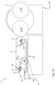
- Figure 1 shows a composite 100 comprising a film winding system 1 according to the invention and a film stretching system 110.
- the film stretching system 110 can be designed as a longitudinal stretching system or transverse stretching system or sequential stretching system with a longitudinal stretching stage and a transverse stretching stage or as a simultaneous stretching system.
- the film stretching system 110 is used to produce a plastic film web 2, which is also referred to below as film web 2.
- the film stretching system 110 is divided into various zones 110a, 110b, 110c, 110d and 110e. Of course, not all of these zones 110a, 110b, 110c, 110d and 110e actually have to be present. In the various zones 110a to 110e, the film web 2 is exposed to different temperatures in order to generate or adjust certain film properties.
- the first zone 110a is also referred to as the preheating zone.
- the second zone 110b is referred to as the stretching zone, whereas the third zone 110c is referred to as the further heating zone.
- the fourth zone 110d is also referred to as the neutral zone, and the fifth zone 110e as the cooling zone.
- film stretching system 110 it is possible to produce film webs with a width that is greater than 2 m, 3 m, 4 m, 5 m, 6 m, 7 m, 8 m, 9 m, 10 m, 11 m or greater than 12 m, but preferably less than 13 m, 12 m, 11 m, 10 m, 9 m, 8 m, 7 m, 6 m, 5 m, 4 m or less than 3 m.
- the film stretching system 110 comprises an input area 111, wherein a film to be stretched can be fed to the film stretching system 110 at its input area 111. At the end of the film stretching system 110, i.e. at its output area 112, the stretched film web 2 exits.
- the exit area 112 of the film stretching system 110 is connected to a film entry area 3 of the film winding system 1 according to the invention.
- Winding battery separator foils is particularly challenging. Winding can only be carried out with low contact force and low foil tension.
- the Figures 2 , 3 , 4 , 5 show exemplary embodiments that describe the film winding system 1.
- the film web 2 is fed from the film stretching system 110 to the film winding system 1. This takes place via the film entry area 3.
- the film web 2 then runs towards a first winding station 4, which is in a winding position.
- the first winding station 4 is designed to wind the film web 2 into a film bale 5 (see Figure 3 ) to wind up.
- the film winding system 1 comprises a contact roller 6 and a dancer roller 8.
- the contact roller 6 is arranged adjacent to the first winding station 4 and is designed to guide the film web 2 to the first winding station 4.
- the dancer roller 8 is arranged in front of the contact roller 6 in the direction of movement of the film web 2 and is designed to guide the film web 2 to the contact roller 6 and to adjust a film tension.
- first deflection roller 9 which is arranged in front of the dancer roller 8 in the direction of movement of the film web 2.
- the film web 2 is fed via the film inlet area 3 to the first deflection roller 9.
- the film web 2 runs over the dancer roller 8 to the contact roller 6 before being wound into a film bale 5 at the first winding station 4.
- the first adjustment device 10 which is designed to move the contact roller 6 in the direction (X-axis) of the winding station 4 or away from the winding station 4. This allows a predetermined contact pressure to be set between the contact roller 6 and the film bale 5. If the contact pressure is above a first threshold value, the contact roller 6 is moved away from the film bale 5. If the contact pressure is below a second threshold value, the contact roller 6 is moved in the direction of the film bale 5.
- the first and second threshold values can be the same or different.
- the first adjustment device 10 comprises a carriage system.
- the carriage system is preferably an air bearing carriage system 11.
- the carriage system A hydrostatic bearing slide system could also be used. This allows the contact roller 6 to be moved with minimal energy expenditure, especially because the initial jerk required to move the contact roller 6 from a rest position is minimal due to air bearings.
- the first adjustment device 10 also includes a linear motor 12, which is designed to move the contact roller 6 via the air bearing carriage system 11 toward the first winding station 4 or away from the first winding station 4. The movement preferably occurs only horizontally (parallel to the floor).
- control device (not shown) which is designed to control the linear motor 12 of the first adjusting device 10 in such a way that the contact roller 6 rests against the film bale 5 with a predetermined contact pressure.
- the first adjustment device 10 also comprises a first and a second radial air bearing 13.
- the contact roller 6 comprises first and second roller journals 15 in the region of the first and second end faces 14. These are mounted in the first and second radial air bearings 13. This eliminates the need for a separate electric motor to drive the contact roller 6.
- the contact roller 6 is preferably set in rotation solely by the film tension of the film web 2. In principle, however, the use of an electric motor would still be possible. Hydrostatic bearings can also be used instead of the first and second radial air bearings 13.
- a second adjustment device 16 is provided and designed to move the dancer roller 8 toward the contact roller 6 or away from the contact roller 6, whereby a specific film tension can be set. If the film tension is to be increased, the dancer roller 8 is moved away from the contact roller 6. This tightens the film. If, on the other hand, the film tension is to be reduced, the dancer roller 8 is moved toward the contact roller 6.
- the second adjustment device 16 also includes an air bearing slide system 17. This allows the dancer roller 8 to be moved with minimal energy expenditure, especially because the jerk required to initially move the dancer roller 8 from a rest position is minimal due to the air bearings.
- the second adjustment device 16 could also include a hydrostatic bearing slide system.
- the second adjustment device 16 also includes a linear motor 18. This is designed to move the dancer roller 8 toward the contact roller 6 or away from the contact roller 6 via the air bearing carriage system 17. The movement preferably occurs only horizontally (parallel to the floor).
- a control device (not shown) is also provided, which is designed to control the linear motor 18 of the second adjustment device 16 such that a predetermined film tension can be applied via the dancer roller 8.
- the film tension can be measured using a force measuring device.
- the air bearing slide system 11 of the first adjustment device 10 also comprises a second rail 26 and at least one second slide 27.
- the second slide 27 comprises air outlet openings directed toward the second rail 26.
- the second slide 27 comprises an air connection 28 through which compressed air can be supplied. This compressed air then exits from the air outlet openings, allowing the second slide 27 to slide along the second rail 26.
Landscapes
- Engineering & Computer Science (AREA)
- Mechanical Engineering (AREA)
- Winding Of Webs (AREA)
- Registering, Tensioning, Guiding Webs, And Rollers Therefor (AREA)
- Advancing Webs (AREA)
- Controlling Rewinding, Feeding, Winding, Or Abnormalities Of Webs (AREA)
- Shaping By String And By Release Of Stress In Plastics And The Like (AREA)
Applications Claiming Priority (1)
| Application Number | Priority Date | Filing Date | Title |
|---|---|---|---|
| DE102021119724.4A DE102021119724A1 (de) | 2021-07-29 | 2021-07-29 | Folienaufwickelsystem, Verbund aus einer Folienreckanlage und einem solchen Folienaufwickelsystem und Verwendung eines solchen Verbunds zur Herstellung von Dünnstfilmen und Membranen |
Publications (4)
| Publication Number | Publication Date |
|---|---|
| EP4124441A2 EP4124441A2 (de) | 2023-02-01 |
| EP4124441A3 EP4124441A3 (de) | 2023-08-09 |
| EP4124441B1 true EP4124441B1 (de) | 2025-03-12 |
| EP4124441C0 EP4124441C0 (de) | 2025-03-12 |
Family
ID=82594908
Family Applications (1)
| Application Number | Title | Priority Date | Filing Date |
|---|---|---|---|
| EP22184819.5A Active EP4124441B1 (de) | 2021-07-29 | 2022-07-13 | Folienaufwickelsystem, verbund aus einer folienreckanlage und einem solchen folienaufwickelsystem und verwendung eines solchen verbunds zur herstellung von dünnstfilmen und membranen |
Country Status (8)
| Country | Link |
|---|---|
| US (1) | US12297063B2 (pl) |
| EP (1) | EP4124441B1 (pl) |
| JP (1) | JP2023021024A (pl) |
| KR (1) | KR102873638B1 (pl) |
| CN (1) | CN115676460A (pl) |
| DE (1) | DE102021119724A1 (pl) |
| HU (1) | HUE071519T2 (pl) |
| PL (1) | PL4124441T3 (pl) |
Families Citing this family (3)
| Publication number | Priority date | Publication date | Assignee | Title |
|---|---|---|---|---|
| CN117227149B (zh) * | 2023-11-15 | 2024-02-20 | 珠海市鼎胜胶粘塑料环保科技有限公司 | 一种自动化薄膜生产装置 |
| DE102023135403A1 (de) * | 2023-12-15 | 2025-06-18 | Brückner Maschinenbau GmbH | Folienaufwickelvorrichtung, Folienherstellungsanlage sowie Verfahren zum Aufwickeln einer Folienbahn |
| CN117944943A (zh) * | 2023-12-29 | 2024-04-30 | 厦门合南道智能科技有限公司 | 包膜张力部件、拉膜机构及包膜设备 |
Family Cites Families (16)
| Publication number | Priority date | Publication date | Assignee | Title |
|---|---|---|---|---|
| US3279718A (en) * | 1965-01-18 | 1966-10-18 | Hobbs Mfg Company | Density control apparatus for roll winding machine |
| DE3600517A1 (de) * | 1986-01-10 | 1987-07-16 | Smg Stahlkontor Maschinenbau G | Wickelmaschine, insbesondere fuer wickel grosser durchmesser |
| EP0237903B1 (en) | 1986-03-17 | 1989-10-25 | Mitsubishi Jukogyo Kabushiki Kaisha | Automatic cutting and winding apparatus for a web-like material such as a film |
| US4868177A (en) * | 1988-11-09 | 1989-09-19 | Hoechst-Roussel Pharmaceuticals, Inc. | 1,2,3,4-tetrahydro-1,9-acridinediamines, pharmaceutical compositions and use |
| JPH0661701B2 (ja) * | 1989-07-28 | 1994-08-17 | オリンパス光学工業株式会社 | ガラス光学素子の成形方法 |
| DE4103799A1 (de) | 1991-02-08 | 1992-08-13 | Kuesters Eduard Maschf | Vorrichtung zum aufwickeln einer kunststoffolienbahn |
| IT1247127B (it) * | 1991-03-04 | 1994-12-12 | Colines Srl | Apparecchio di avvolgimento per nastro di materiale a foglio |
| US5308008A (en) * | 1992-03-18 | 1994-05-03 | Rueegg Anton | Method and apparatus for producing rolls |
| DE19620670C2 (de) | 1996-05-22 | 1998-07-23 | Liba Maschf | Vorrichtung zum Aufwickeln einer Wirkwarenbahn |
| DE19629205A1 (de) * | 1996-07-19 | 1998-01-22 | Voith Sulzer Papiermasch Gmbh | Verfahren und Vorrichtung zum Aufwickeln einer Papierbahn zu einer Rolle mit aktiver Schwingungsdämpfung |
| EP0855355B1 (de) * | 1997-01-25 | 2005-03-09 | Voith Paper Patent GmbH | Wickelmaschine und Verfahren zum kontinuierlichen Aufwickeln einer Materialbahn |
| FI114209B (fi) * | 2002-06-14 | 2004-09-15 | Metso Paper Inc | Menetelmä kuiturainarullan esim. paperi- tai kartonkirullan rakenteen säätämiseksi |
| CH705791A1 (de) * | 2011-11-21 | 2013-05-31 | Swiss Winding Inventing Ag | Verfahren zur Herstellung eines Wickels aus einer Materialbahn von flexiblem Material, sowie Wickler zur Ausführung dieses Verfahrens. |
| ITMI20130758A1 (it) * | 2013-05-09 | 2014-11-10 | No El Srl | Macchina per la produzione di bobine di film estensibile prestirato con dispositivo di avvolgimento perfezionato |
| DE102019112089A1 (de) | 2019-05-09 | 2020-11-12 | Brückner Maschinenbau GmbH & Co. KG | Folie mit wenigstens zwei Schichten und Verfahren zu ihrer Herstellung |
| DE102019119600A1 (de) | 2019-07-19 | 2021-01-21 | Brückner Maschinenbau GmbH & Co. KG | Inline beschichtete biaxial orientierte Polyethylenfolie und Verfahren zu ihrer Herstellung |
-
2021
- 2021-07-29 DE DE102021119724.4A patent/DE102021119724A1/de active Pending
-
2022
- 2022-07-13 PL PL22184819.5T patent/PL4124441T3/pl unknown
- 2022-07-13 HU HUE22184819A patent/HUE071519T2/hu unknown
- 2022-07-13 EP EP22184819.5A patent/EP4124441B1/de active Active
- 2022-07-25 KR KR1020220091792A patent/KR102873638B1/ko active Active
- 2022-07-27 JP JP2022119222A patent/JP2023021024A/ja active Pending
- 2022-07-28 US US17/876,359 patent/US12297063B2/en active Active
- 2022-07-29 CN CN202210903114.1A patent/CN115676460A/zh active Pending
Also Published As
| Publication number | Publication date |
|---|---|
| KR102873638B1 (ko) | 2025-10-22 |
| EP4124441A2 (de) | 2023-02-01 |
| US20230036198A1 (en) | 2023-02-02 |
| KR20230019391A (ko) | 2023-02-08 |
| US12297063B2 (en) | 2025-05-13 |
| PL4124441T3 (pl) | 2025-08-18 |
| EP4124441A3 (de) | 2023-08-09 |
| CN115676460A (zh) | 2023-02-03 |
| HUE071519T2 (hu) | 2025-09-28 |
| EP4124441C0 (de) | 2025-03-12 |
| JP2023021024A (ja) | 2023-02-09 |
| DE102021119724A1 (de) | 2023-02-02 |
Similar Documents
| Publication | Publication Date | Title |
|---|---|---|
| EP4124441B1 (de) | Folienaufwickelsystem, verbund aus einer folienreckanlage und einem solchen folienaufwickelsystem und verwendung eines solchen verbunds zur herstellung von dünnstfilmen und membranen | |
| EP3919422B1 (de) | Folienwickelsystem und verbund aus einer folienreckanlage und einem solchen folienwickelsystem | |
| EP3119583B1 (de) | Winkelverstellbare anpress- oder nipwalze | |
| EP2849929B1 (de) | Blasfolienanlage, verfahren zum herstellen einer blasfolienbahn und damit hergestellte folie | |
| DE2528370C3 (de) | Verfahren zum Herstellen von biaxial verstreckten Folienbahnen aus Kunststoff und Vorrichtung zur Durchführung des Verfahrens | |
| EP3057770B1 (de) | Verfahren zum herstellen einer blasfolienbahn sowie blasfolienanlage | |
| DE102013012134A1 (de) | Vorrichtung zur Herstellung von inline gereckten Folien | |
| EP1851027B1 (de) | Vorrichtung und Verfahren zum Antrieb einer Vorheizwalzenanordnung in einer Kalander-Vorrichtung | |
| EP4281229B1 (de) | Kaltwalzvorrichtung und verfahren zum geregelten kaltwalzen von aluminiumfolie | |
| EP2079654B1 (de) | Schwenkbare anlegewalze im wendewickler | |
| EP0442253B1 (de) | Folienstreckanlage | |
| DE102011109385A1 (de) | Variables Längsreckwerk für das Verstrecken einer Kunststofffolie | |
| EP4041524A1 (de) | Blasfolienanlage und verfahren zur herstellung von folienschläuchen oder folienbahnen | |
| EP2508327A1 (de) | Verfahren und Vorrichtung zur Verarbeitung eines Bandes | |
| EP3233417B1 (de) | Folienmaschine und verfahren zur herstellung von stretchfolien | |
| EP4570720A1 (de) | Folienaufwickelvorrichtung, folienherstellungsanlage sowie verfahren zum aufwickeln einer folienbahn | |
| DE102012107370B4 (de) | Vorrichtung und Verfahren zur Herstellung eines Energiespeichers | |
| DE102019215782A1 (de) | Blasfolienanlage und Verfahren zur Herstellung einer Folienbahn | |
| DE202022002884U1 (de) | Kunststoffformgebende Anlage | |
| DE102019131761A1 (de) | Walzlinie | |
| WO2020094649A1 (de) | Verfahren für eine kalibrierung von stellmitteln zur verstellung eines düsenspaltes einer austrittsdüse für eine folienbahn an einer flachfolienmaschine | |
| EP3466642A1 (de) | Vorrichtung und verfahren zum aufwickeln eines materialstreifens | |
| DE2656743A1 (pl) |
Legal Events
| Date | Code | Title | Description |
|---|---|---|---|
| PUAI | Public reference made under article 153(3) epc to a published international application that has entered the european phase |
Free format text: ORIGINAL CODE: 0009012 |
|
| STAA | Information on the status of an ep patent application or granted ep patent |
Free format text: STATUS: THE APPLICATION HAS BEEN PUBLISHED |
|
| AK | Designated contracting states |
Kind code of ref document: A2 Designated state(s): AL AT BE BG CH CY CZ DE DK EE ES FI FR GB GR HR HU IE IS IT LI LT LU LV MC MK MT NL NO PL PT RO RS SE SI SK SM TR |
|
| RAP3 | Party data changed (applicant data changed or rights of an application transferred) |
Owner name: BRUECKNER MASCHINENBAU GMBH |
|
| PUAL | Search report despatched |
Free format text: ORIGINAL CODE: 0009013 |
|
| AK | Designated contracting states |
Kind code of ref document: A3 Designated state(s): AL AT BE BG CH CY CZ DE DK EE ES FI FR GB GR HR HU IE IS IT LI LT LU LV MC MK MT NL NO PL PT RO RS SE SI SK SM TR |
|
| RIC1 | Information provided on ipc code assigned before grant |
Ipc: B29C 53/32 20060101ALI20230630BHEP Ipc: B29C 55/02 20060101AFI20230630BHEP |
|
| STAA | Information on the status of an ep patent application or granted ep patent |
Free format text: STATUS: REQUEST FOR EXAMINATION WAS MADE |
|
| 17P | Request for examination filed |
Effective date: 20240202 |
|
| RBV | Designated contracting states (corrected) |
Designated state(s): AL AT BE BG CH CY CZ DE DK EE ES FI FR GB GR HR HU IE IS IT LI LT LU LV MC MK MT NL NO PL PT RO RS SE SI SK SM TR |
|
| GRAP | Despatch of communication of intention to grant a patent |
Free format text: ORIGINAL CODE: EPIDOSNIGR1 |
|
| STAA | Information on the status of an ep patent application or granted ep patent |
Free format text: STATUS: GRANT OF PATENT IS INTENDED |
|
| INTG | Intention to grant announced |
Effective date: 20241001 |
|
| GRAS | Grant fee paid |
Free format text: ORIGINAL CODE: EPIDOSNIGR3 |
|
| GRAA | (expected) grant |
Free format text: ORIGINAL CODE: 0009210 |
|
| STAA | Information on the status of an ep patent application or granted ep patent |
Free format text: STATUS: THE PATENT HAS BEEN GRANTED |
|
| AK | Designated contracting states |
Kind code of ref document: B1 Designated state(s): AL AT BE BG CH CY CZ DE DK EE ES FI FR GB GR HR HU IE IS IT LI LT LU LV MC MK MT NL NO PL PT RO RS SE SI SK SM TR |
|
| REG | Reference to a national code |
Ref country code: GB Ref legal event code: FG4D Free format text: NOT ENGLISH |
|
| REG | Reference to a national code |
Ref country code: CH Ref legal event code: EP |
|
| REG | Reference to a national code |
Ref country code: DE Ref legal event code: R096 Ref document number: 502022003146 Country of ref document: DE |
|
| REG | Reference to a national code |
Ref country code: IE Ref legal event code: FG4D Free format text: LANGUAGE OF EP DOCUMENT: GERMAN |
|
| U01 | Request for unitary effect filed |
Effective date: 20250402 |
|
| U07 | Unitary effect registered |
Designated state(s): AT BE BG DE DK EE FI FR IT LT LU LV MT NL PT RO SE SI Effective date: 20250409 |
|
| PG25 | Lapsed in a contracting state [announced via postgrant information from national office to epo] |
Ref country code: RS Free format text: LAPSE BECAUSE OF FAILURE TO SUBMIT A TRANSLATION OF THE DESCRIPTION OR TO PAY THE FEE WITHIN THE PRESCRIBED TIME-LIMIT Effective date: 20250612 |
|
| PG25 | Lapsed in a contracting state [announced via postgrant information from national office to epo] |
Ref country code: ES Free format text: LAPSE BECAUSE OF FAILURE TO SUBMIT A TRANSLATION OF THE DESCRIPTION OR TO PAY THE FEE WITHIN THE PRESCRIBED TIME-LIMIT Effective date: 20250312 |
|
| PG25 | Lapsed in a contracting state [announced via postgrant information from national office to epo] |
Ref country code: NO Free format text: LAPSE BECAUSE OF FAILURE TO SUBMIT A TRANSLATION OF THE DESCRIPTION OR TO PAY THE FEE WITHIN THE PRESCRIBED TIME-LIMIT Effective date: 20250612 |
|
| PG25 | Lapsed in a contracting state [announced via postgrant information from national office to epo] |
Ref country code: HR Free format text: LAPSE BECAUSE OF FAILURE TO SUBMIT A TRANSLATION OF THE DESCRIPTION OR TO PAY THE FEE WITHIN THE PRESCRIBED TIME-LIMIT Effective date: 20250312 |
|
| PG25 | Lapsed in a contracting state [announced via postgrant information from national office to epo] |
Ref country code: GR Free format text: LAPSE BECAUSE OF FAILURE TO SUBMIT A TRANSLATION OF THE DESCRIPTION OR TO PAY THE FEE WITHIN THE PRESCRIBED TIME-LIMIT Effective date: 20250613 |
|
| U20 | Renewal fee for the european patent with unitary effect paid |
Year of fee payment: 4 Effective date: 20250729 |
|
| PGFP | Annual fee paid to national office [announced via postgrant information from national office to epo] |
Ref country code: HU Payment date: 20250829 Year of fee payment: 4 |
|
| REG | Reference to a national code |
Ref country code: HU Ref legal event code: AG4A Ref document number: E071519 Country of ref document: HU |
|
| PG25 | Lapsed in a contracting state [announced via postgrant information from national office to epo] |
Ref country code: SM Free format text: LAPSE BECAUSE OF FAILURE TO SUBMIT A TRANSLATION OF THE DESCRIPTION OR TO PAY THE FEE WITHIN THE PRESCRIBED TIME-LIMIT Effective date: 20250312 |
|
| PGFP | Annual fee paid to national office [announced via postgrant information from national office to epo] |
Ref country code: TR Payment date: 20250819 Year of fee payment: 4 Ref country code: PL Payment date: 20250818 Year of fee payment: 4 |
|
| PG25 | Lapsed in a contracting state [announced via postgrant information from national office to epo] |
Ref country code: CZ Free format text: LAPSE BECAUSE OF FAILURE TO SUBMIT A TRANSLATION OF THE DESCRIPTION OR TO PAY THE FEE WITHIN THE PRESCRIBED TIME-LIMIT Effective date: 20250312 |
|
| PG25 | Lapsed in a contracting state [announced via postgrant information from national office to epo] |
Ref country code: SK Free format text: LAPSE BECAUSE OF FAILURE TO SUBMIT A TRANSLATION OF THE DESCRIPTION OR TO PAY THE FEE WITHIN THE PRESCRIBED TIME-LIMIT Effective date: 20250312 |
|
| PG25 | Lapsed in a contracting state [announced via postgrant information from national office to epo] |
Ref country code: IS Free format text: LAPSE BECAUSE OF FAILURE TO SUBMIT A TRANSLATION OF THE DESCRIPTION OR TO PAY THE FEE WITHIN THE PRESCRIBED TIME-LIMIT Effective date: 20250712 |
|
| PLBE | No opposition filed within time limit |
Free format text: ORIGINAL CODE: 0009261 |
|
| STAA | Information on the status of an ep patent application or granted ep patent |
Free format text: STATUS: NO OPPOSITION FILED WITHIN TIME LIMIT |
|
| REG | Reference to a national code |
Ref country code: CH Ref legal event code: L10 Free format text: ST27 STATUS EVENT CODE: U-0-0-L10-L00 (AS PROVIDED BY THE NATIONAL OFFICE) Effective date: 20260121 |