EP4123779A1 - Batterie secondaire à électrolyte non aqueux - Google Patents
Batterie secondaire à électrolyte non aqueux Download PDFInfo
- Publication number
- EP4123779A1 EP4123779A1 EP21770987.2A EP21770987A EP4123779A1 EP 4123779 A1 EP4123779 A1 EP 4123779A1 EP 21770987 A EP21770987 A EP 21770987A EP 4123779 A1 EP4123779 A1 EP 4123779A1
- Authority
- EP
- European Patent Office
- Prior art keywords
- positive electrode
- plate
- current collector
- electrode
- negative electrode
- Prior art date
- Legal status (The legal status is an assumption and is not a legal conclusion. Google has not performed a legal analysis and makes no representation as to the accuracy of the status listed.)
- Pending
Links
- 239000011255 nonaqueous electrolyte Substances 0.000 title claims abstract description 20
- 238000007789 sealing Methods 0.000 claims abstract description 29
- 239000011241 protective layer Substances 0.000 claims abstract description 28
- 239000007774 positive electrode material Substances 0.000 claims abstract description 11
- 229910052809 inorganic oxide Inorganic materials 0.000 claims description 3
- 238000005452 bending Methods 0.000 description 10
- 238000004804 winding Methods 0.000 description 8
- 239000010410 layer Substances 0.000 description 7
- 239000007773 negative electrode material Substances 0.000 description 7
- 239000011149 active material Substances 0.000 description 6
- 230000000052 comparative effect Effects 0.000 description 3
- 239000003792 electrolyte Substances 0.000 description 3
- 238000004519 manufacturing process Methods 0.000 description 3
- 238000000034 method Methods 0.000 description 3
- 239000011230 binding agent Substances 0.000 description 2
- 238000002347 injection Methods 0.000 description 2
- 239000007924 injection Substances 0.000 description 2
- 239000011347 resin Substances 0.000 description 2
- 229920005989 resin Polymers 0.000 description 2
- RYGMFSIKBFXOCR-UHFFFAOYSA-N Copper Chemical compound [Cu] RYGMFSIKBFXOCR-UHFFFAOYSA-N 0.000 description 1
- HBBGRARXTFLTSG-UHFFFAOYSA-N Lithium ion Chemical compound [Li+] HBBGRARXTFLTSG-UHFFFAOYSA-N 0.000 description 1
- 239000002033 PVDF binder Substances 0.000 description 1
- 229910052782 aluminium Inorganic materials 0.000 description 1
- XAGFODPZIPBFFR-UHFFFAOYSA-N aluminium Chemical compound [Al] XAGFODPZIPBFFR-UHFFFAOYSA-N 0.000 description 1
- PNEYBMLMFCGWSK-UHFFFAOYSA-N aluminium oxide Inorganic materials [O-2].[O-2].[O-2].[Al+3].[Al+3] PNEYBMLMFCGWSK-UHFFFAOYSA-N 0.000 description 1
- 239000003575 carbonaceous material Substances 0.000 description 1
- 239000000919 ceramic Substances 0.000 description 1
- 238000007796 conventional method Methods 0.000 description 1
- 239000011889 copper foil Substances 0.000 description 1
- 239000011888 foil Substances 0.000 description 1
- 229910001416 lithium ion Inorganic materials 0.000 description 1
- 239000000463 material Substances 0.000 description 1
- 229910052751 metal Inorganic materials 0.000 description 1
- 239000002184 metal Substances 0.000 description 1
- 238000012986 modification Methods 0.000 description 1
- 230000004048 modification Effects 0.000 description 1
- 229920002981 polyvinylidene fluoride Polymers 0.000 description 1
- 239000000843 powder Substances 0.000 description 1
Images


Classifications
-
- H—ELECTRICITY
- H01—ELECTRIC ELEMENTS
- H01M—PROCESSES OR MEANS, e.g. BATTERIES, FOR THE DIRECT CONVERSION OF CHEMICAL ENERGY INTO ELECTRICAL ENERGY
- H01M10/00—Secondary cells; Manufacture thereof
- H01M10/05—Accumulators with non-aqueous electrolyte
- H01M10/058—Construction or manufacture
- H01M10/0587—Construction or manufacture of accumulators having only wound construction elements, i.e. wound positive electrodes, wound negative electrodes and wound separators
-
- H—ELECTRICITY
- H01—ELECTRIC ELEMENTS
- H01M—PROCESSES OR MEANS, e.g. BATTERIES, FOR THE DIRECT CONVERSION OF CHEMICAL ENERGY INTO ELECTRICAL ENERGY
- H01M50/00—Constructional details or processes of manufacture of the non-active parts of electrochemical cells other than fuel cells, e.g. hybrid cells
- H01M50/50—Current conducting connections for cells or batteries
- H01M50/572—Means for preventing undesired use or discharge
- H01M50/584—Means for preventing undesired use or discharge for preventing incorrect connections inside or outside the batteries
- H01M50/586—Means for preventing undesired use or discharge for preventing incorrect connections inside or outside the batteries inside the batteries, e.g. incorrect connections of electrodes
-
- H—ELECTRICITY
- H01—ELECTRIC ELEMENTS
- H01M—PROCESSES OR MEANS, e.g. BATTERIES, FOR THE DIRECT CONVERSION OF CHEMICAL ENERGY INTO ELECTRICAL ENERGY
- H01M10/00—Secondary cells; Manufacture thereof
- H01M10/04—Construction or manufacture in general
-
- H—ELECTRICITY
- H01—ELECTRIC ELEMENTS
- H01M—PROCESSES OR MEANS, e.g. BATTERIES, FOR THE DIRECT CONVERSION OF CHEMICAL ENERGY INTO ELECTRICAL ENERGY
- H01M10/00—Secondary cells; Manufacture thereof
- H01M10/04—Construction or manufacture in general
- H01M10/0431—Cells with wound or folded electrodes
-
- H—ELECTRICITY
- H01—ELECTRIC ELEMENTS
- H01M—PROCESSES OR MEANS, e.g. BATTERIES, FOR THE DIRECT CONVERSION OF CHEMICAL ENERGY INTO ELECTRICAL ENERGY
- H01M10/00—Secondary cells; Manufacture thereof
- H01M10/05—Accumulators with non-aqueous electrolyte
-
- H—ELECTRICITY
- H01—ELECTRIC ELEMENTS
- H01M—PROCESSES OR MEANS, e.g. BATTERIES, FOR THE DIRECT CONVERSION OF CHEMICAL ENERGY INTO ELECTRICAL ENERGY
- H01M10/00—Secondary cells; Manufacture thereof
- H01M10/05—Accumulators with non-aqueous electrolyte
- H01M10/052—Li-accumulators
-
- H—ELECTRICITY
- H01—ELECTRIC ELEMENTS
- H01M—PROCESSES OR MEANS, e.g. BATTERIES, FOR THE DIRECT CONVERSION OF CHEMICAL ENERGY INTO ELECTRICAL ENERGY
- H01M10/00—Secondary cells; Manufacture thereof
- H01M10/05—Accumulators with non-aqueous electrolyte
- H01M10/052—Li-accumulators
- H01M10/0525—Rocking-chair batteries, i.e. batteries with lithium insertion or intercalation in both electrodes; Lithium-ion batteries
-
- H—ELECTRICITY
- H01—ELECTRIC ELEMENTS
- H01M—PROCESSES OR MEANS, e.g. BATTERIES, FOR THE DIRECT CONVERSION OF CHEMICAL ENERGY INTO ELECTRICAL ENERGY
- H01M10/00—Secondary cells; Manufacture thereof
- H01M10/05—Accumulators with non-aqueous electrolyte
- H01M10/058—Construction or manufacture
- H01M10/0585—Construction or manufacture of accumulators having only flat construction elements, i.e. flat positive electrodes, flat negative electrodes and flat separators
-
- H—ELECTRICITY
- H01—ELECTRIC ELEMENTS
- H01M—PROCESSES OR MEANS, e.g. BATTERIES, FOR THE DIRECT CONVERSION OF CHEMICAL ENERGY INTO ELECTRICAL ENERGY
- H01M4/00—Electrodes
- H01M4/02—Electrodes composed of, or comprising, active material
- H01M4/13—Electrodes for accumulators with non-aqueous electrolyte, e.g. for lithium-accumulators; Processes of manufacture thereof
-
- H—ELECTRICITY
- H01—ELECTRIC ELEMENTS
- H01M—PROCESSES OR MEANS, e.g. BATTERIES, FOR THE DIRECT CONVERSION OF CHEMICAL ENERGY INTO ELECTRICAL ENERGY
- H01M50/00—Constructional details or processes of manufacture of the non-active parts of electrochemical cells other than fuel cells, e.g. hybrid cells
- H01M50/10—Primary casings; Jackets or wrappings
- H01M50/102—Primary casings; Jackets or wrappings characterised by their shape or physical structure
- H01M50/103—Primary casings; Jackets or wrappings characterised by their shape or physical structure prismatic or rectangular
-
- H—ELECTRICITY
- H01—ELECTRIC ELEMENTS
- H01M—PROCESSES OR MEANS, e.g. BATTERIES, FOR THE DIRECT CONVERSION OF CHEMICAL ENERGY INTO ELECTRICAL ENERGY
- H01M50/00—Constructional details or processes of manufacture of the non-active parts of electrochemical cells other than fuel cells, e.g. hybrid cells
- H01M50/10—Primary casings; Jackets or wrappings
- H01M50/172—Arrangements of electric connectors penetrating the casing
- H01M50/174—Arrangements of electric connectors penetrating the casing adapted for the shape of the cells
- H01M50/176—Arrangements of electric connectors penetrating the casing adapted for the shape of the cells for prismatic or rectangular cells
-
- H—ELECTRICITY
- H01—ELECTRIC ELEMENTS
- H01M—PROCESSES OR MEANS, e.g. BATTERIES, FOR THE DIRECT CONVERSION OF CHEMICAL ENERGY INTO ELECTRICAL ENERGY
- H01M50/00—Constructional details or processes of manufacture of the non-active parts of electrochemical cells other than fuel cells, e.g. hybrid cells
- H01M50/10—Primary casings; Jackets or wrappings
- H01M50/172—Arrangements of electric connectors penetrating the casing
- H01M50/174—Arrangements of electric connectors penetrating the casing adapted for the shape of the cells
- H01M50/178—Arrangements of electric connectors penetrating the casing adapted for the shape of the cells for pouch or flexible bag cells
-
- H—ELECTRICITY
- H01—ELECTRIC ELEMENTS
- H01M—PROCESSES OR MEANS, e.g. BATTERIES, FOR THE DIRECT CONVERSION OF CHEMICAL ENERGY INTO ELECTRICAL ENERGY
- H01M50/00—Constructional details or processes of manufacture of the non-active parts of electrochemical cells other than fuel cells, e.g. hybrid cells
- H01M50/50—Current conducting connections for cells or batteries
- H01M50/528—Fixed electrical connections, i.e. not intended for disconnection
-
- H—ELECTRICITY
- H01—ELECTRIC ELEMENTS
- H01M—PROCESSES OR MEANS, e.g. BATTERIES, FOR THE DIRECT CONVERSION OF CHEMICAL ENERGY INTO ELECTRICAL ENERGY
- H01M50/00—Constructional details or processes of manufacture of the non-active parts of electrochemical cells other than fuel cells, e.g. hybrid cells
- H01M50/50—Current conducting connections for cells or batteries
- H01M50/531—Electrode connections inside a battery casing
- H01M50/533—Electrode connections inside a battery casing characterised by the shape of the leads or tabs
-
- H—ELECTRICITY
- H01—ELECTRIC ELEMENTS
- H01M—PROCESSES OR MEANS, e.g. BATTERIES, FOR THE DIRECT CONVERSION OF CHEMICAL ENERGY INTO ELECTRICAL ENERGY
- H01M50/00—Constructional details or processes of manufacture of the non-active parts of electrochemical cells other than fuel cells, e.g. hybrid cells
- H01M50/50—Current conducting connections for cells or batteries
- H01M50/531—Electrode connections inside a battery casing
- H01M50/534—Electrode connections inside a battery casing characterised by the material of the leads or tabs
-
- H—ELECTRICITY
- H01—ELECTRIC ELEMENTS
- H01M—PROCESSES OR MEANS, e.g. BATTERIES, FOR THE DIRECT CONVERSION OF CHEMICAL ENERGY INTO ELECTRICAL ENERGY
- H01M50/00—Constructional details or processes of manufacture of the non-active parts of electrochemical cells other than fuel cells, e.g. hybrid cells
- H01M50/50—Current conducting connections for cells or batteries
- H01M50/531—Electrode connections inside a battery casing
- H01M50/536—Electrode connections inside a battery casing characterised by the method of fixing the leads to the electrodes, e.g. by welding
-
- H—ELECTRICITY
- H01—ELECTRIC ELEMENTS
- H01M—PROCESSES OR MEANS, e.g. BATTERIES, FOR THE DIRECT CONVERSION OF CHEMICAL ENERGY INTO ELECTRICAL ENERGY
- H01M50/00—Constructional details or processes of manufacture of the non-active parts of electrochemical cells other than fuel cells, e.g. hybrid cells
- H01M50/50—Current conducting connections for cells or batteries
- H01M50/531—Electrode connections inside a battery casing
- H01M50/538—Connection of several leads or tabs of wound or folded electrode stacks
-
- H—ELECTRICITY
- H01—ELECTRIC ELEMENTS
- H01M—PROCESSES OR MEANS, e.g. BATTERIES, FOR THE DIRECT CONVERSION OF CHEMICAL ENERGY INTO ELECTRICAL ENERGY
- H01M50/00—Constructional details or processes of manufacture of the non-active parts of electrochemical cells other than fuel cells, e.g. hybrid cells
- H01M50/50—Current conducting connections for cells or batteries
- H01M50/543—Terminals
- H01M50/547—Terminals characterised by the disposition of the terminals on the cells
- H01M50/55—Terminals characterised by the disposition of the terminals on the cells on the same side of the cell
-
- H—ELECTRICITY
- H01—ELECTRIC ELEMENTS
- H01M—PROCESSES OR MEANS, e.g. BATTERIES, FOR THE DIRECT CONVERSION OF CHEMICAL ENERGY INTO ELECTRICAL ENERGY
- H01M50/00—Constructional details or processes of manufacture of the non-active parts of electrochemical cells other than fuel cells, e.g. hybrid cells
- H01M50/50—Current conducting connections for cells or batteries
- H01M50/543—Terminals
- H01M50/552—Terminals characterised by their shape
- H01M50/553—Terminals adapted for prismatic, pouch or rectangular cells
-
- H—ELECTRICITY
- H01—ELECTRIC ELEMENTS
- H01M—PROCESSES OR MEANS, e.g. BATTERIES, FOR THE DIRECT CONVERSION OF CHEMICAL ENERGY INTO ELECTRICAL ENERGY
- H01M50/00—Constructional details or processes of manufacture of the non-active parts of electrochemical cells other than fuel cells, e.g. hybrid cells
- H01M50/50—Current conducting connections for cells or batteries
- H01M50/543—Terminals
- H01M50/562—Terminals characterised by the material
-
- H—ELECTRICITY
- H01—ELECTRIC ELEMENTS
- H01M—PROCESSES OR MEANS, e.g. BATTERIES, FOR THE DIRECT CONVERSION OF CHEMICAL ENERGY INTO ELECTRICAL ENERGY
- H01M50/00—Constructional details or processes of manufacture of the non-active parts of electrochemical cells other than fuel cells, e.g. hybrid cells
- H01M50/50—Current conducting connections for cells or batteries
- H01M50/543—Terminals
- H01M50/564—Terminals characterised by their manufacturing process
- H01M50/566—Terminals characterised by their manufacturing process by welding, soldering or brazing
-
- H—ELECTRICITY
- H01—ELECTRIC ELEMENTS
- H01M—PROCESSES OR MEANS, e.g. BATTERIES, FOR THE DIRECT CONVERSION OF CHEMICAL ENERGY INTO ELECTRICAL ENERGY
- H01M50/00—Constructional details or processes of manufacture of the non-active parts of electrochemical cells other than fuel cells, e.g. hybrid cells
- H01M50/50—Current conducting connections for cells or batteries
- H01M50/572—Means for preventing undesired use or discharge
-
- Y—GENERAL TAGGING OF NEW TECHNOLOGICAL DEVELOPMENTS; GENERAL TAGGING OF CROSS-SECTIONAL TECHNOLOGIES SPANNING OVER SEVERAL SECTIONS OF THE IPC; TECHNICAL SUBJECTS COVERED BY FORMER USPC CROSS-REFERENCE ART COLLECTIONS [XRACs] AND DIGESTS
- Y02—TECHNOLOGIES OR APPLICATIONS FOR MITIGATION OR ADAPTATION AGAINST CLIMATE CHANGE
- Y02E—REDUCTION OF GREENHOUSE GAS [GHG] EMISSIONS, RELATED TO ENERGY GENERATION, TRANSMISSION OR DISTRIBUTION
- Y02E60/00—Enabling technologies; Technologies with a potential or indirect contribution to GHG emissions mitigation
- Y02E60/10—Energy storage using batteries
-
- Y—GENERAL TAGGING OF NEW TECHNOLOGICAL DEVELOPMENTS; GENERAL TAGGING OF CROSS-SECTIONAL TECHNOLOGIES SPANNING OVER SEVERAL SECTIONS OF THE IPC; TECHNICAL SUBJECTS COVERED BY FORMER USPC CROSS-REFERENCE ART COLLECTIONS [XRACs] AND DIGESTS
- Y02—TECHNOLOGIES OR APPLICATIONS FOR MITIGATION OR ADAPTATION AGAINST CLIMATE CHANGE
- Y02P—CLIMATE CHANGE MITIGATION TECHNOLOGIES IN THE PRODUCTION OR PROCESSING OF GOODS
- Y02P70/00—Climate change mitigation technologies in the production process for final industrial or consumer products
- Y02P70/50—Manufacturing or production processes characterised by the final manufactured product
Definitions
- the present disclosure relates to a non-aqueous electrolyte secondary battery.
- a non-aqueous electrolyte secondary battery such as a lithium ion battery has a structure in which an electrode body is accommodated in an exterior body having an opening and the opening is sealed with a sealing plate.
- the electrode body has a structure in which a positive electrode and a negative electrode are stacked with a separator interposed therebetween.
- Patent Document 1 discloses an electrode body having a structure in which multiple positive electrode plates and multiple negative electrode plates are stacked with separators interposed therebetween, and an electrode body in which a long positive electrode plate and a long negative electrode plate are stacked and wound with a long separator interposed therebetween.
- positive electrode tabs for current collection extend from the positive electrode plates
- negative electrode tabs for current collection extend from the negative electrode plates.
- multiple positive electrode tabs extend from the long positive electrode plate
- multiple negative electrode tabs extend from the long negative electrode plate.
- Patent Document 2 also discloses an electrode body having a structure in which multiple positive electrode plates and multiple negative electrode plates are stacked with separators interposed therebetween. Positive electrode tabs extend from the positive electrode plates, and negative electrode tabs extend from the negative electrode plates.
- All types of batteries are designed such that an active material in the negative electrode has a greater capacity than an active material in the positive electrode, and batteries in which the positive electrode plate and the negative electrode plate are stacked to face each other are designed such that the area of the positive electrode plate to which the active material is applied falls within the area of the negative electrode plate to which the active material is applied and the area to which the negative electrode active material is applied is larger than (extends beyond) the area to which the positive electrode active material is applied.
- the area to which the positive electrode active material is applied and the area to which the negative electrode active material is applied are designed to be as large as possible.
- burrs may be generated when the tabs are formed by cutting parts of the positive electrode plate and the negative electrode plate.
- burrs are likely to be generated when corner portions are formed, and the bases of the tabs are assumed to be portions where burrs are likely to be generated.
- the positive electrode plate is designed so that the area of the positive electrode plate to which the positive electrode active material is applied is as large as possible in order to increase the battery capacity, the bases of the positive electrode tabs may be overlaid on the negative electrode plate.
- the positive electrode tabs are separated from the negative electrode plate by the separator, the following problem may occur when the burrs, which are metal, are generated at the bases of the positive electrode tabs. The burrs may break the separator, come into contact with the negative electrode plate, and cause short-circuit.
- a non-aqueous electrolyte secondary battery includes an electrode body including a positive electrode plate and a negative electrode plate, a rectangular exterior body having an opening and accommodating the electrode body, a sealing plate sealing the opening, an electrode terminal provided to the sealing plate, a first current collector disposed between the electrode body and the sealing plate and connected to the electrode terminal, a second current collector disposed between the electrode body and a side wall of the rectangular exterior body and connected to the first current collector, and a tab group extending from the electrode body toward the side wall and connected to the second current collector.
- the second current collector is made of a flat plate having a surface parallel to the side wall.
- the tab group includes a positive electrode tab group having a bundle of multiple positive electrode tabs extending from the positive electrode plate and a negative electrode tab group having a bundle of multiple negative electrode tabs extending from the negative electrode plate, and is bent near a connection with the second current collector to be parallel to the side wall.
- the positive electrode plate includes a positive electrode core and a positive electrode active material applied to the positive electrode core, the positive electrode tabs extend from the positive electrode core, a surface of the positive electrode core on and near its end from which the positive electrode tabs extend is covered with a protective layer containing an insulant, and the protective layer is exposed.
- the positive electrode plate and the negative electrode plate in the electrode body are stacked with a separator interposed therebetween. One end of the negative electrode plate faces the protective layer on the positive electrode plate.
- the positive electrode tab group is located on one end surface of the electrode body, and the negative electrode tab group is located on the other end surface of the electrode body.
- the end of the protective layer and one end of the negative electrode plate are spaced at least 0.1 mm apart in plan view.
- the positive electrode tabs are partially provided with the protective layer.
- the insulant includes an inorganic oxide.
- the end portion of the positive electrode plate on the side on which the positive electrode tabs extend is covered with the protective layer, and the end of the negative electrode plate faces the protective layer. This ensures a high safety.
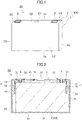
- FIG. 1 is a perspective view of a non-aqueous electrolyte secondary battery according to the present disclosure.
- FIG. 2 is a sectional view of the battery of FIG. 1 , taken along a line parallel to the plane of paper.
- a non-aqueous electrolyte secondary battery 20 includes a battery case 100 having a rectangular exterior body 1 having an opening and a bottomed rectangular tube shape and a sealing plate 2 sealing the opening of the rectangular exterior body 1.
- the rectangular exterior body 1 has a bottom 1a, a pair of first side walls 1b and 1c, and a pair of second side walls 1d and 1e.
- the first side walls 1b and 1c in pair are disposed to face each other.
- the second side walls 1d and 1e in pair are disposed to face each other.
- the pair of first side walls 1b and 1c is perpendicular to the longitudinal direction of the sealing plate 2, and the area of the pair of first side walls 1b and 1c is smaller than that of the pair of second side walls 1d and 1e.
- an electrode body 3 including a positive electrode plate 4 and a negative electrode plate 5 is accommodated together with an electrolyte.
- the electrode body 3 is a flat electrode body in which the positive electrode plate 4 and the negative electrode plate 5 are wound with a separator interposed therebetween.
- the winding axis of the electrode body 3 extends perpendicularly to the first side walls 1b and 1c and parallel to the second side walls 1d and 1e.
- the electrode body 3 is not limited to the wound electrode body, and may be, for example, a stacked electrode body in which multiple positive electrode plates 4 and multiple negative electrode plates 5 are stacked with separators interposed therebetween.
- reference numeral 10 denotes an external insulating member disposed between the sealing plate 2 and a positive electrode terminal 8
- reference numeral 12 denotes an external insulating member disposed between the sealing plate 2 and a negative electrode terminal 9.
- Reference numeral 11 denotes an inner insulating member disposed between the sealing plate 2 and a first positive electrode current collector 61
- reference numeral 13 denotes an inner insulating member disposed between the sealing plate 2 and a first negative electrode current collector 71.
- Reference numeral 14 denotes a box-shaped or bag-shaped insulating sheet which is disposed inside the rectangular exterior body 1 and accommodates the electrode body 3.
- Reference numeral 15 denotes an electrolyte injection hole provided in the sealing plate 2.
- Reference numeral 16 denotes a sealing member sealing the electrolyte injection hole 15.
- Reference numeral 17 denotes a gas discharge valve provided in the sealing plate 2.
- one side is a positive electrode side and the other side is a negative electrode side in a direction in which the winding axis of the electrode body 3 extends.
- the positive electrode side is mainly described below, and description of the negative electrode side may be omitted.
- the positive electrode plate 4 has a long strip-like shape, and has a region in which a positive electrode active material layer 4a is formed on each surface of a positive electrode core (e.g., an aluminum foil).
- a positive electrode core e.g., an aluminum foil.
- Multiple positive electrode tabs 4b extend in a raised shape from one end of the positive electrode core in the lateral direction of the positive electrode plate 4.
- the surface of the positive electrode core on and near the one end in the lateral direction of the positive electrode plate 4 is covered with a protective layer 4c.
- the protective layer 4c is provided with a constant width from one side (end) extending in the longitudinal direction of the positive electrode plate 4 toward the longitudinal center axis of the positive electrode plate 4.
- the protective layer is also provided at the base of each positive electrode tab 4b.
- the protective layer 4c contains an insulant, and may be, for example, an insulating layer made of resin or a layer containing ceramic, which is an inorganic oxide, and a resin binder.
- the protective layer 4c can be, for example, a layer containing an alumina powder, a carbon material as an electroconductive material, and polyvinylidene fluoride as a binder.
- the negative electrode plate 5 has a long strip-like shape, and has a region in which a negative electrode active material layer 5a is formed on each surface of a negative electrode core (e.g., a copper foil).
- a negative electrode core e.g., a copper foil.
- Multiple negative electrode tabs 5b extend in a raised shape from one end of the negative electrode core in the lateral direction of the negative electrode plate 5.
- the positive electrode plate 4 and the negative electrode plate 5 are stacked with the separator interposed therebetween and wound to form the electrode body 3.
- the winding axis extends in a direction (the lateral direction in FIG. 6 ) connecting a positive electrode tab group 40 and a negative electrode tab group 50, and the positive electrode tab group 40 is located on one end surface of the electrode body 3 perpendicular to the winding axis and the negative electrode tab group 50 is located on the other end surface opposite to the one end surface.
- Such a positional relationship easily prevents or reduces short-circuit in the battery.
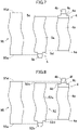
- FIG. 7 is a schematic view showing a positional relationship among the positive electrode plate 4, the negative electrode plate 5, and a separator 95 in the present embodiment
- FIG. 8 is a similar view showing a positional relationship among the positive electrode plate 4, a negative electrode plate 52, and the separator 95 in a comparative configuration.
- a battery having a structure in which a positive electrode plate and a negative electrode plate are stacked on each other is designed such that the area of the positive electrode plate to which an active material is applied always falls within the area of the negative electrode plate to which an active material is applied, and an area to which the negative electrode active material is applied is larger than (extends beyond) an area to which the positive electrode active material is applied.
- the same protective layer 4c as that provided on the positive electrode plate 4 is also provided at the base of each positive electrode tab 4b, and in FIG. 8 , one end 52e of the negative electrode plate 52 is located between the upper end 4f of the protective layer provided on the positive electrode tab 4b and the end 4d of the positive electrode plate 4.
- One end 95e of the separator 95 faces the negative electrode tabs 52b of the negative electrode plate 52, the other end 95d faces the positive electrode tab 4b of the positive electrode plate 4, and the separator 95 entirely covers the positive electrode active material layer 4a and the negative electrode active material layer 52a.
- the position of one end 5e of the negative electrode plate 5 is changed to the inside of the corresponding end (end of the protective layer 4c) 4d of the positive electrode plate 4 so as to face the protective layer 4c of the positive electrode plate 4.
- the distance between an end 4d which is an end of the protective layer 4c on the positive electrode plate 4 and one end 5e of the negative electrode plate 5 is 0.1 mm or more in plan view (when viewed perpendicularly to the surfaces of the positive electrode plate 4 and the negative electrode plate 5).
- the distance is set to 0.15 mm or more because short-circuit can be more reliably prevented or reduced.
- the comparative configuration shown in FIG. 8 differs from the present embodiment shown in FIG. 7 only in the position of one end 5e, 52e of the negative electrode plate 5, 52; otherwise, the configuration and the structure are the same.
- the sealing plate 2 is provided with the positive electrode terminal 8 and the negative electrode terminal 9 as electrode terminals to the outside.
- the positive electrode terminal 8 is electrically connected to the positive electrode tab group 40 with the positive electrode current collector 6 interposed therebetween.
- the positive electrode current collector 6 includes a first positive electrode current collector 61 and a second positive electrode current collector 62.
- the negative electrode terminal 9 is electrically connected to the negative electrode tab group 50 with the negative electrode current collector 7 interposed therebetween.
- the negative electrode current collector 7 includes a first negative electrode current collector 71 and a second negative electrode current collector 72.
- the first positive electrode current collector 61 has a substantially L-shaped cross section and is disposed between the electrode body 3 and the sealing plate 2. Specifically, the first positive electrode current collector 61 has a first region disposed along the sealing plate 2 and a second region bent from an end of the first region. The second region extends along the first side wall 1b toward the bottom 1a. The first positive electrode current collector 61 is in connection with the positive electrode terminal 8.
- the negative electrode side has a similar configuration.
- the second positive electrode current collector 62 is disposed between the electrode body 3 and the first side wall 1b of the rectangular exterior body 1. Specifically, the second positive electrode current collector 62 is made of a flat plate having a surface parallel to the first side wall 1b, and extends along the first side wall 1b toward the bottom 1a. The second positive electrode current collector 62 is in connection with the first positive electrode current collector 61.
- the negative electrode side has a similar configuration.
- FIG. 3 shows the second positive electrode current collector 62.
- the second positive electrode current collector 62 has a structure in which a substantially rectangular flat plate is partially bent, and includes a current collector connector 62a, an inclined portion 62b, and a tab connector 62c.
- the current collector connector 62a is connected to the first positive electrode current collector 61.
- the positive electrode tab group 40 is connected to the tab connector 62c.
- the inclined portion 62b connects the current collector connector 62a and the tab connector 62c, and is inclined with respect to both of these connectors.
- the current collector connector 62a is provided with a recess 62d.
- the recess 62d has a through hole 62e.
- the current collector connector 62a is joined to the first positive electrode current collector 61.
- the second positive electrode current collector 62 is further provided with a fuse 66.
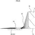
- FIG. 9 shows the vicinity of the connection between the second positive electrode current collector 62 and the positive electrode tab group 40 before bending the positive electrode tab group 40.
- FIG. 11 shows the electrode body 3 where the positive electrode tab group 40 is connected to the second positive electrode current collector 62 and the negative electrode tab group 50 is connected to the second negative electrode current collector 72 before bending the positive electrode tab group 40 and the negative electrode tab group 50.
- the positive electrode tab group 40 is connected to the tab connector 62c in the second positive electrode current collector 62. Specifically, as shown in FIG. 9 , the tab connector 62c and the positive electrode tab group 40 are joined (welded) with the positive electrode tab group 40 disposed on the tab connector 62c of the second positive electrode current collector 62 before bending the positive electrode tab group 40, thereby forming a connection 63.
- the positive electrode tab group 40 is in connection with the tab connector 62c of the second positive electrode current collector 62 on one side (right side in FIG. 9 ) in the width direction of the flat plate forming the second positive electrode current collector 62.
- the connection 63 between the positive electrode tab group 40 and the tab connector 62c is closer to the base (one side in the width direction, the right side in FIG. 9 ) of the positive electrode tab group 40 in the width direction of the flat plate. Accordingly, when the positive electrode tab group 40 is bent, a curved shape can be more reliably formed in the vicinity of the base of the positive electrode tab group 40 in a stable manner.
- FIG. 10 is a view showing the vicinity of the connection between the second positive electrode current collector 62 and the positive electrode tab group 40 after bending the positive electrode tab group 40.
- the positive electrode tab group 40 is bent so that the tab connector 62c of the second positive electrode current collector 62 disposed substantially parallel to the first main surface 3a and the second main surface 3b of the electrode body 3 (see FIGS. 9 and 11 ) is oriented substantially perpendicularly to the winding axis of the electrode body 3.
- the positive electrode tab group 40 is bent near the connection 63 with the second positive electrode current collector 62 to be parallel to the first side wall 1b.
- the bent positive electrode tab group 40 is fixed to the electrode body 3 with a tape 80.
- the positive electrode tab group 40 can be bent without bending the second positive electrode current collector 62. This enables manufacturing of non-aqueous electrolyte secondary batteries with a high volumetric energy density by a simple method.
- the negative electrode side has a configuration similar to the positive electrode side, and in FIG. 11 , reference numeral 72a denotes a current collector connector, reference numeral 72b denotes an inclined portion, and reference numeral 72c denotes a tab connector.
- the positive electrode tab group 40 and the negative electrode tab group 50 are bent, which allows the battery to have a high volumetric energy density without bending the second current collectors 62 and 72.
- One end 5e of the negative electrode plate 5 is disposed to face the protective layer 4c on the positive electrode plate 4, thereby substantially preventing or reducing short-circuit in the battery.
- the above-described embodiment is a mere example of the present invention.
- the present invention is not limited to such an example.
- the present invention may be a combination of a well-known art, a conventional technique, and a publicly-known technique with the example, and may also have a part of the example replaced.
- the present invention encompasses any modification easily conceivable by a person skilled in the art.
- the non-aqueous electrolyte secondary battery 20 may include multiple electrode bodies 3.
- FIG. 12 is a view showing an electrode body group 300 including the multiple electrode bodies 3. As shown in FIG. 12 , the non-aqueous electrolyte secondary battery 20 includes the multiple (two) electrode bodies 3. A second current collector 62 is connected to a positive electrode tab group 40 of each electrode body 3. The multiple electrode bodies 3 and 3 are arranged and fixed together with a tape 90 to form the electrode body group 300.
- FIG. 13 is a view showing the electrode body group 300 and a sealing plate 2 connected to each other by a first positive electrode current collector 61 and second positive electrode current collectors 62.
Landscapes
- Chemical & Material Sciences (AREA)
- Chemical Kinetics & Catalysis (AREA)
- Electrochemistry (AREA)
- General Chemical & Material Sciences (AREA)
- Engineering & Computer Science (AREA)
- Manufacturing & Machinery (AREA)
- Materials Engineering (AREA)
- Connection Of Batteries Or Terminals (AREA)
- Secondary Cells (AREA)
Applications Claiming Priority (2)
| Application Number | Priority Date | Filing Date | Title |
|---|---|---|---|
| JP2020049779 | 2020-03-19 | ||
| PCT/JP2021/004629 WO2021186948A1 (fr) | 2020-03-19 | 2021-02-08 | Batterie secondaire à électrolyte non aqueux |
Publications (1)
| Publication Number | Publication Date |
|---|---|
| EP4123779A1 true EP4123779A1 (fr) | 2023-01-25 |
Family
ID=77770837
Family Applications (1)
| Application Number | Title | Priority Date | Filing Date |
|---|---|---|---|
| EP21770987.2A Pending EP4123779A1 (fr) | 2020-03-19 | 2021-02-08 | Batterie secondaire à électrolyte non aqueux |
Country Status (5)
| Country | Link |
|---|---|
| US (1) | US20230104632A1 (fr) |
| EP (1) | EP4123779A1 (fr) |
| JP (1) | JPWO2021186948A1 (fr) |
| CN (1) | CN115298895A (fr) |
| WO (1) | WO2021186948A1 (fr) |
Family Cites Families (10)
| Publication number | Priority date | Publication date | Assignee | Title |
|---|---|---|---|---|
| JP4366783B2 (ja) * | 1998-11-16 | 2009-11-18 | 株式会社デンソー | 積層型電池及びその電極の製造方法 |
| CN100590927C (zh) | 2006-12-02 | 2010-02-17 | 比亚迪股份有限公司 | 一种锂离子电池及其制作方法 |
| JP5354042B2 (ja) | 2012-02-27 | 2013-11-27 | 株式会社豊田自動織機 | 蓄電装置、車両 |
| JP2017050069A (ja) * | 2015-08-31 | 2017-03-09 | 株式会社豊田自動織機 | 蓄電装置 |
| KR101870801B1 (ko) * | 2016-01-21 | 2018-06-28 | 주식회사 루트제이드 | 박막형 전지 |
| JP6768418B2 (ja) * | 2016-08-31 | 2020-10-14 | 三洋電機株式会社 | 角形二次電池 |
| JP2018056023A (ja) * | 2016-09-30 | 2018-04-05 | 日立オートモティブシステムズ株式会社 | 二次電池 |
| JP6575557B2 (ja) * | 2017-04-07 | 2019-09-18 | トヨタ自動車株式会社 | 全固体電池及び全固体電池の製造方法 |
| JP7035348B6 (ja) * | 2017-06-29 | 2022-04-01 | 三洋電機株式会社 | 角形二次電池及びその製造方法 |
| KR102371196B1 (ko) * | 2017-08-31 | 2022-03-07 | 삼성에스디아이 주식회사 | 이차 전지 |
-
2021
- 2021-02-08 US US17/911,203 patent/US20230104632A1/en active Pending
- 2021-02-08 CN CN202180021499.2A patent/CN115298895A/zh active Pending
- 2021-02-08 JP JP2022508127A patent/JPWO2021186948A1/ja active Pending
- 2021-02-08 EP EP21770987.2A patent/EP4123779A1/fr active Pending
- 2021-02-08 WO PCT/JP2021/004629 patent/WO2021186948A1/fr unknown
Also Published As
| Publication number | Publication date |
|---|---|
| US20230104632A1 (en) | 2023-04-06 |
| CN115298895A (zh) | 2022-11-04 |
| WO2021186948A1 (fr) | 2021-09-23 |
| JPWO2021186948A1 (fr) | 2021-09-23 |
Similar Documents
| Publication | Publication Date | Title |
|---|---|---|
| JP4484782B2 (ja) | 二次電池 | |
| KR100807029B1 (ko) | 이차전지 | |
| EP3905404B1 (fr) | Batterie secondaire | |
| EP3799182A1 (fr) | Batterie secondaire, bloc-batterie et dispositif électrique | |
| KR101744090B1 (ko) | 단락부재는 갖는 이차 전지 | |
| US10811650B2 (en) | Secondary battery | |
| WO2024027005A1 (fr) | Élément adaptateur, cellule de batterie, batterie et dispositif électrique | |
| US11476526B2 (en) | Secondary battery, battery module and vehicle | |
| EP4123820A1 (fr) | Batterie secondaire à électrolyte non aqueux | |
| CN114614208A (zh) | 电池 | |
| US20230033391A1 (en) | Non-aqueous electrolyte secondary battery | |
| EP4123779A1 (fr) | Batterie secondaire à électrolyte non aqueux | |
| US11088426B2 (en) | Electric storage device | |
| KR101957311B1 (ko) | 2차 전지 | |
| CN113258215A (zh) | 二次电池 | |
| CN115719864A (zh) | 电池 | |
| EP4080639A1 (fr) | Batterie secondaire à électrolyte non aqueux | |
| US20220320572A1 (en) | Secondary battery | |
| JP7414701B2 (ja) | 二次電池及び組電池 | |
| EP4131462A1 (fr) | Batterie secondaire à électrolyte non aqueux | |
| CN114725477A (zh) | 电芯单元、电池及电池的装配方法 | |
| JP7264676B2 (ja) | 密閉型電池用絶縁板及びそれを備えた密閉型電池 | |
| KR101285898B1 (ko) | 이차전지 | |
| US20220302559A1 (en) | Secondary battery | |
| CN217062447U (zh) | 电池 |
Legal Events
| Date | Code | Title | Description |
|---|---|---|---|
| STAA | Information on the status of an ep patent application or granted ep patent |
Free format text: STATUS: THE INTERNATIONAL PUBLICATION HAS BEEN MADE |
|
| PUAI | Public reference made under article 153(3) epc to a published international application that has entered the european phase |
Free format text: ORIGINAL CODE: 0009012 |
|
| STAA | Information on the status of an ep patent application or granted ep patent |
Free format text: STATUS: REQUEST FOR EXAMINATION WAS MADE |
|
| 17P | Request for examination filed |
Effective date: 20220907 |
|
| AK | Designated contracting states |
Kind code of ref document: A1 Designated state(s): AL AT BE BG CH CY CZ DE DK EE ES FI FR GB GR HR HU IE IS IT LI LT LU LV MC MK MT NL NO PL PT RO RS SE SI SK SM TR |
|
| DAV | Request for validation of the european patent (deleted) | ||
| DAX | Request for extension of the european patent (deleted) |