EP4123315A1 - Sicherheits-kontaktiervorrichtung zum erkennen von kabeln von solarzellen und zum messen von gleich- und wechselspannungen und strömen an weiteren spannungsführenden kabeln - Google Patents
Sicherheits-kontaktiervorrichtung zum erkennen von kabeln von solarzellen und zum messen von gleich- und wechselspannungen und strömen an weiteren spannungsführenden kabeln Download PDFInfo
- Publication number
- EP4123315A1 EP4123315A1 EP22020350.9A EP22020350A EP4123315A1 EP 4123315 A1 EP4123315 A1 EP 4123315A1 EP 22020350 A EP22020350 A EP 22020350A EP 4123315 A1 EP4123315 A1 EP 4123315A1
- Authority
- EP
- European Patent Office
- Prior art keywords
- cable
- measuring electrode
- cables
- safety
- measuring
- Prior art date
- Legal status (The legal status is an assumption and is not a legal conclusion. Google has not performed a legal analysis and makes no representation as to the accuracy of the status listed.)
- Granted
Links
Images



Classifications
-
- G—PHYSICS
- G01—MEASURING; TESTING
- G01R—MEASURING ELECTRIC VARIABLES; MEASURING MAGNETIC VARIABLES
- G01R1/00—Details of instruments or arrangements of the types included in groups G01R5/00 - G01R13/00 and G01R31/00
- G01R1/02—General constructional details
- G01R1/04—Housings; Supporting members; Arrangements of terminals
- G01R1/0408—Test fixtures or contact fields; Connectors or connecting adaptors; Test clips; Test sockets
- G01R1/0416—Connectors, terminals
-
- H—ELECTRICITY
- H02—GENERATION; CONVERSION OR DISTRIBUTION OF ELECTRIC POWER
- H02S—GENERATION OF ELECTRIC POWER BY CONVERSION OF INFRARED RADIATION, VISIBLE LIGHT OR ULTRAVIOLET LIGHT, e.g. USING PHOTOVOLTAIC [PV] MODULES
- H02S50/00—Monitoring or testing of PV systems, e.g. load balancing or fault identification
- H02S50/10—Testing of PV devices, e.g. of PV modules or single PV cells
-
- G—PHYSICS
- G01—MEASURING; TESTING
- G01R—MEASURING ELECTRIC VARIABLES; MEASURING MAGNETIC VARIABLES
- G01R1/00—Details of instruments or arrangements of the types included in groups G01R5/00 - G01R13/00 and G01R31/00
- G01R1/02—General constructional details
- G01R1/06—Measuring leads; Measuring probes
- G01R1/067—Measuring probes
- G01R1/06788—Hand-held or hand-manipulated probes, e.g. for oscilloscopes or for portable test instruments
-
- G—PHYSICS
- G01—MEASURING; TESTING
- G01R—MEASURING ELECTRIC VARIABLES; MEASURING MAGNETIC VARIABLES
- G01R31/00—Arrangements for testing electric properties; Arrangements for locating electric faults; Arrangements for electrical testing characterised by what is being tested not provided for elsewhere
- G01R31/50—Testing of electric apparatus, lines, cables or components for short-circuits, continuity, leakage current or incorrect line connections
- G01R31/55—Testing for incorrect line connections
-
- Y—GENERAL TAGGING OF NEW TECHNOLOGICAL DEVELOPMENTS; GENERAL TAGGING OF CROSS-SECTIONAL TECHNOLOGIES SPANNING OVER SEVERAL SECTIONS OF THE IPC; TECHNICAL SUBJECTS COVERED BY FORMER USPC CROSS-REFERENCE ART COLLECTIONS [XRACs] AND DIGESTS
- Y02—TECHNOLOGIES OR APPLICATIONS FOR MITIGATION OR ADAPTATION AGAINST CLIMATE CHANGE
- Y02E—REDUCTION OF GREENHOUSE GAS [GHG] EMISSIONS, RELATED TO ENERGY GENERATION, TRANSMISSION OR DISTRIBUTION
- Y02E10/00—Energy generation through renewable energy sources
- Y02E10/50—Photovoltaic [PV] energy
Definitions
- the invention relates to a safety contacting device for detecting two cables belonging to one another in a solar cell series circuit.
- Solar cells which are often also referred to as solar panels, are arranged on the walls of houses and on the roofs of houses. Solar cells convert solar energy into electrical energy. They are usually connected in series to add the DC voltages they generate.
- an initial cable preferably leads downwards from a first solar cell from the roof or a house wall, and an end cable leads downwards from a last solar cell of the solar cells connected in series.
- the two cables are routed into a basement or utility room of a building to be wired there.
- the fitter In a cellar or utility room, the fitter is faced with the task of always finding the two cables that belong together in a tangled bundle of very many cables that form a pair, namely the respective start cable of a first solar cell connected in series and the associated end cable of the last solar cell the series.
- each cable must be handled by the installer and a measuring electrode, such as a lead leading to a multimeter, must be used to physically contact the metallic cable core of each cable.
- the fitter must first take a first cable and bring it into contact with a first measuring electrode. This first measuring electrode and the first cable must be kept in contact by the fitter with one hand, the fitter then having to use the other hand to identify the cable belonging to the first cable from the bundle of cables by applying a second measuring electrode to the metallic core of a second cable. The fitter must therefore test all the remaining cables until he has found the right one. There is a risk that the fitter will slip off a metal core and touch the metal core with his finger. If the human body comes into direct contact with the metallic cable cores of such a pair, a DC voltage of up to 3000 volts is applied to it, which can lead to considerable damage to health.
- the clamping device consists of an electrically non-conductive cylindrical part with a rectangular groove at the end.
- an eccentric rotatably mounted non-toothed tension roller made of non-conductive material with a high coefficient of friction is arranged transversely to the axial direction.
- a cylindrical bore is arranged in the axial direction, which opens or ends in the rectangular groove.
- a conductor to be tested is fed with its conductor end into the groove between the bottom of the groove and the tension roller until its cross-sectional area hits a contact surface of a contact piston and the contact piston is displaced in the axial direction against the force of the helical spring, so that the contact piston surface and the cross-sectional area of the conductor electrical contact is made.
- the tensioning roller By turning the tensioning roller, the conductor is clamped between the base of the groove and the tensioning roller. The tension roller is automatically held in this position by the force of the coil spring on the conductor.
- the clamping device DD 120 978 A1 can be used in particular for testing a large number of isolated individual conductors to carry out a voltage test of each individual conductor against all other individual conductors.
- the invention is based on the object of creating a safety contacting device in which the cables in the safety contacting device can be contacted more reliably than in the prior art.
- the present invention solves the aforementioned problem by the features of claim 1.
- a safety contacting device for detecting two cables belonging to one another in a solar cell series connection can prevent the fitter from coming into direct physical contact with the metallic core of a cable. Furthermore, it has been recognized that at least one first measuring electrode must be guided with a tip for application to the core of a first cable in order to reliably hit the metallic core of the cable and without the fitter moving the measuring electrode himself. It has also been recognized that a base body with a cable receptacle for inserting and holding at least one of the cables can feed the cable directly when the measuring electrode is inserted. It has also been recognized that the measuring electrode must be guided inside the base body by means of guides so that the metal core can be hit accurately and physically contacted without stripping the cable.
- a cable retainer fixes the cable at least to some extent and keeps it in contact with the measuring electrode without the installer having to actively hold the measuring electrode against the metallic core.
- the cable holder should be arranged coaxially to the axis of movement through the measuring electrode, so that the tip of the measuring electrode always hits the metallic core of the first cable. Thanks to this safety contact device, the fitter now has both hands free to feel the metallic core of a second cable with a second measuring electrode and thereby find out the cable that forms a pair with the cable in the safety contact device, namely a pair of initial - and end cable forms.
- the safety contactor also ensures that the fitter can no longer be harmed by DC voltage, because the only cable which, together with the cable he is holding by hand, could apply a voltage to his human body is already held in the safety contactor .
- the cable holder shields the cable held in it, namely in particular the metallic core, against unwanted access.
- the guide means could include a spring, by which the measuring electrode is resiliently mounted, the spring being movable against a restoring force.
- a cable can be pushed into the cable holder until the measuring electrode is pressed against the metal core.
- the measuring electrode provides the cable with flexible resistance when it is pushed in.
- Locking means could be assigned to the cable receptacle in order to secure the cable against slipping out of the cable receptacle.
- the locking means could press against the sheath of the cable and thereby fix it in a non-positive manner.
- the locking means could be manually operable by an actuator to release or fix the cable. In this way, the fitter can actively determine whether a cable should remain in the cable holder or should be pulled out of it.
- the actuating device could have a lever which can be pivoted about a pivot axis.
- a lever is easily operable with a finger, especially the thumb.
- the lever could be spring-loaded so that a locking means automatically presses radially inwards when the lever is not pressed or released.
- the base body could have at least one line with a plug, the line being electrically conductively connected to the measuring electrode.
- the safety contact device can easily be connected to a standard measuring device to measure electrical currents and voltages, for example a multimeter.
- the base body could have two cable receptacles, each with a measuring electrode assigned to the respective cable receptacle. In this way, two cables can always be plugged into the safety contact device and the fitter can then operate the measuring device more easily.
- a cable receptacle could have a plurality of locking areas arranged one behind the other, each with a different inner diameter than another locking area.
- cables of different thicknesses can be used in the safety contacting device described here.
- the safety contact device could be connected to a measuring device for measuring electrical currents or voltages by means of a line, or the base body could be designed in one piece with such a measuring device. Due to the one-piece configuration of the safety contacting device or several safety contacting devices with a measuring device, in particular a multimeter, cables for solar cells can be checked and examined particularly easily.
- the safety contact device described here is preferably used to test cables from solar cells.
- the DIN standards for cables used as solar cables are as follows: DIN EN 60228 class 5 (conductor construction), EN 60811, EN 50267-2-1, EN 50363.
- the DIN standards for measuring devices and test adapters are as follows : IEC 61010-1 (international), DIN EN 61010-1 (German version) or VDE classification VDE 0411-1, product standards for devices for testing, measuring or monitoring protective measures: IEC 61557 parts 1 to 16 (international), DIN EN 61557 Parts 1 to 16 (German version) or DIN VDE 0413 Parts 1 to 16.
- the currently valid product standards are EC 61010-1:2010 + Cor.:2011, DIN EN 61010-1:2011-07 and VDE 0411-1: 2011-07.
- the present invention solves the aforementioned problem by the features of claim 11.
- the safety contact device described here is used to detect cables from solar cells and to carry out measurements to determine DC and AC voltages and currents on other live cables.
- FIG. 1 shows a schematic view of several rows of solar cells 1 connected in series, whose respective start and end cables 2a, 3a, 4a, 2b, 3b, 4b are routed within a tangled bundle of cables with cable ends present in a disorderly manner into a supply room 5 of a building for further wiring by a fitter are.
- a series of several solar cells 1 can build up 750 to 3000 volts between an initial cable 2a, 3a, 4a and an end cable 2b, 3b, 4b.
- a cable 2a, 3a, 4a, 2b, 3b, 4b can have a metallic core of 4 mm 2 , 6 mm 2 , 10 mm 2 or 16 mm 2 .
- 1 shows by the dashed detail A the non-stripped end of a tail cable 2b, which forms a pair with the head cable 2a from which a DC voltage can be tapped.
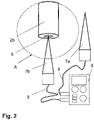
- FIG. 2 shows a schematic view of the detail A from 1 , namely a cable end whose metallic core 6 is physically contacted by a measuring electrode 7b (more precisely: its tip), whereby the measuring electrode 7b is connected to a multimeter 9 by means of a line 8, from which a further line 8 is connected to a further measuring electrode which is still free 7a exits.
- the installer now has to get out of the bundle of cables 1 find out the starting cable 2a by bringing the still free measuring electrode 7a into contact with the remaining cables 2a, 3a, 4a, 3b, 4b until the multimeter 9 shows a direct voltage.
- the fitter must ensure that he does not come into physical contact with the two metal cores 6 of the starter cable 2a and the end cable 2b at the same time.
- FIG 3 shows a schematic sectional view of a safety contacting device with a spring-loaded measuring electrode 7b, which is in electrical and physical contact with a metallic core 6 of a cable, here the end cable 2b.
- This safety contactor is used to detect two cables that belong together, namely a start cable 2a and a finish cable 2b, a solar cell series connection used.
- the safety contacting device comprises at least one measuring electrode 7b for application to the core 6 of a cable, namely the end cable 2b, and is characterized by a base body 10 with a cable receptacle 11 for inserting and holding the end cable 2b, with the measuring electrode 7b inside the base body 10 is guided by guide means.
- the guide means comprise a spring 12, for example a spiral spring, by which the measuring electrode 7b is resiliently mounted, the measuring electrode 7b being movable against a restoring force.
- the measuring electrode 7b is designed as an elongated contact pin, on the rim 13 of which the spring 12 is attached with an in 3 right end.
- the left end of the spring 12 is supported on a guide sleeve 14 into which the contact pin can dip and which establishes electrical contact between the contact pin and a line 8 .
- the cable holder 11 is arranged coaxially to the movement axis through the measuring electrode 7b.
- the movement axis through the measuring electrode 7b coincides with the horizontal double arrow 3 together.
- the double arrow expresses the fact that the measuring electrode 7b can spring in and out, depending on whether the end cable 2b is inserted into or led out of the cable receptacle 11, which is open on one side.
- the cable holder 11 is preferably made of a plastic or another electrically insulating material.
- Locking means 15 are associated with the cable receptacle 11 in order to secure the cable against slipping out of the cable receptacle 11 .
- the locking means 15 are movable radially inwards to press against the sheath of the cable. The cable is thus firmly fixed in the cable receptacle 11 when its core 6 contacts the measuring electrode 7b.
- the radial mobility of the locking means 15 is indicated by the vertical double arrow in 3 and 4 shown.
- a free measuring electrode 7a can now be used as in 2 described are used.
- the fitter now has both hands free because the tail cable 2b in accordance with the safety contactor 3 is securely fixed.
- FIG. 1 shows, based on a further embodiment of the safety contacting device, that a base body 10a has two cable receptacles 11a, 11b, one of which receives the starter cable 2a and the other one the end cable 2b in a fixed manner.
- a device 16 is provided inside the base body 10a, which has two spring-loaded measuring electrodes 7a, 7b in analogy to 3 having. In this way, two cables can always be examined and the fitter has both hands free to operate the multimeter 9 .
- the locking means 15 can be manually operated by an actuating device in order to release or fix a cable.
- the actuating device has a lever 17 which can be pivoted about a pivot axis. This is represented by the curved double arrow.
- both cables can also be released or fixed at the same time by a lever 17 .
- two levers 17 are provided, so that each cable can be detached or fixed on its own.
- the base body 10, 10a has at least one line 8 with a plug, the line 8 being electrically conductively connected to the measuring electrode 7b or 7a. If two measuring electrodes 7a, 7b are provided, two lines 8 leading to the multimeter 9 are provided.
- FIG. 1 shows that the base body 10a has two cable receptacles 11a, 11b, each with a measuring electrode 7a, 7b assigned to the respective cable receptacle 11a, 11b.
- the measuring device is preferably a correspondingly modified multimeter 9.
- a cable holder has 11c has a plurality of locking areas arranged one behind the other, each with a different internal diameter to another, adjacent locking area.
- figure 5 shows such a cable holder 11c.
- the different inside diameters of the locking areas with locking means 15 are represented by dashed double arrows.
- the cable holder 11c can be fitted with a safety contactor according to FIG 3 or 4 , but can also be combined with a modified multimeter 9 if this multimeter 9 forms the safety contacting device.
- the locking area with the largest inside diameter faces away from the measuring electrode 7b, the locking area with the smallest inside diameter faces the measuring electrode 7b.
- Introductory bevels can be formed between the locking areas, so that a cable can be inserted better, that is to say it can be threaded in as it were.
- the installer can therefore carry a safety contactor of the type described here.
Landscapes
- Physics & Mathematics (AREA)
- General Physics & Mathematics (AREA)
- Measuring Leads Or Probes (AREA)
- Details Of Connecting Devices For Male And Female Coupling (AREA)
- Geophysics And Detection Of Objects (AREA)
Abstract
Description
- Die Erfindung betrifft eine Sicherheits-Kontaktiervorrichtung zum Erkennen von zwei zueinander gehörenden Kabeln einer Solarzellenreihenschaltung.
- Aus der
WO 2009/132 468 A2 sind Solarzellen bekannt. Solarzellen, die häufig auch als Solarpaneele bezeichnet werden, sind an Häuserwänden und auf Dächern von Häusern angeordnet. Solarzellen wandeln Sonnenenergie in elektrische Energie um. Sie werden üblicherweise in Reihe geschaltet, um die von ihnen erzeugten Gleichspannungen zu addieren. - Zum Abgreifen und Nutzen der Gleichspannung führt von einer ersten Solarzelle ein Anfangskabel vom Dach oder einer Häuserwand bevorzugt nach unten, und führt von einer letzten Solarzelle der in Reihe geschalteten Solarzellen ein Endkabel nach unten. Üblicherweise werden die beiden Kabel in einen Keller oder Versorgungsraum eines Gebäudes geführt, um dort verdrahtet zu werden.
- Da auf einem Dach oder an einer Häuserwand aber nicht nur eine Reihe von Solarzellen, sondern eine Vielzahl von Reihen angeordnet sein können, führen nicht nur zwei Kabel, also ein zugehöriges Paar, in den Keller, sondern eine Vielzahl von Paaren, an denen eine Gleichspannung abgegriffen werden kann.
- Der Monteur sieht sich in einem Keller oder Versorgungsraum der Aufgabe gegenüber, aus einem wirren Bündel von sehr vielen Kabeln stets die zwei zusammengehörigen Kabel herauszufinden, die ein Paar bilden, nämlich das jeweilige Anfangskabel einer in Reihe geschalteten ersten Solarzelle und das zugehörige Endkabel der letzten Solarzelle der Reihe.
- Da die Solarzellen Gleichspannung erzeugen, ist eine kontaktfreie elektrische Vermessung der Kabel nicht möglich. Jedes Kabel muss vom Monteur in die Hand genommen werden, und mit einer Messelektrode, beispielsweise einer Leitung, die zu einem Multimeter führt, muss der metallische Kabelkern jedes Kabels physisch kontaktiert werden.
- Damit die Gleichspannung detektiert werden kann, muss der Monteur also zunächst ein erstes Kabel in die Hand nehmen und mit einer ersten Messelektrode in Kontakt bringen. Diese erste Messelektrode und das erste Kabel müssen vom Monteur mit einer Hand in Kontakt verbleibend gehalten werden, wobei der Monteur dann mit der anderen Hand aus dem Bündel an Kabeln das zum ersten Kabel zugehörige Kabel ermitteln muss, indem er eine zweite Messelektrode an den metallischen Kern eines zweiten Kabels führt. Der Monteur muss also alle noch verbleibenden Kabel durchtesten, bis er das richtige gefunden hat. Hierbei besteht die Gefahr, dass der Monteur von einem metallischen Kern abrutscht und mit seinem Finger an den metallischen Kern gelangt. Wenn der menschliche Körper in direkten Kontakt mit den metallischen Kabelkernen eines solchen Paars kommt, liegt an ihm eine Gleichspannung von bis zu 3000 Volt an, was zu erheblichen gesundheitlichen Schäden führen kann.
- Aus der
DD 120 978 A1 DD 120 978 A1 - Der Erfindung liegt die Aufgabe zu Grunde, eine Sicherheits-Kontaktiervorrichtung zu schaffen, bei denen die Kabel in der Sicherheits-Kontaktiervorrichtung zuverlässiger als im Stand der Technik kontaktierbar sind.
- Die vorliegende Erfindung löst die zuvor genannte Aufgabe durch die Merkmale des Anspruchs 1.
- Erfindungsgemäß ist erkannt worden, dass eine Sicherheits-Kontaktiervorrichtung zum Erkennen von zwei zueinander gehörenden Kabeln einer Solarzellenreihenschaltung verhindern kann, dass der Monteur in unmittelbaren körperlichen Kontakt mit dem metallischen Kern eines Kabels kommen kann. Weiter ist erkannt worden, dass mindestens eine erste Messelektrode mit einer Spitze zum Anlegen an den Kern eines ersten Kabels gerichtet geführt werden muss, um den metallischen Kern des Kabels sicher zu treffen und zwar ohne, dass der Monteur die Messelektrode selbst bewegt. Weiter ist erkannt worden, dass ein Grundkörper mit einer Kabelaufnahme zum Einführen und Halten mindestens eines der Kabel das Kabel beim Einführen der Messelektrode direkt zuführen kann. Weiter ist erkannt worden, dass die Messelektrode innerhalb des Grundkörpers durch Führungsmittel geführt werden muss, damit der metallische Kern, ohne das Kabel abzuisolieren, zielsicher getroffen und physisch kontaktiert werden kann. Auch ist erkannt worden, dass eine Kabelaufnahme das Kabel zumindest zu einem gewissen Maß fixiert und mit der Messelektrode in Kontakt hält, ohne dass der Monteur aktiv die Messelektrode gegen den metallischen Kern gedrückt halten muss. Schließlich ist erkannt worden, dass die Kabelaufnahme koaxial zur Bewegungsachse durch die Messelektrode angeordnet sein sollte, so dass die Spitze der Messelektrode stets den metallischen Kern des ersten Kabels trifft. Durch diese Sicherheits-Kontaktiervorrichtung hat der Monteur nun beide Hände frei, um mit einer zweiten Messelektrode den metallischen Kern eines zweiten Kabels zu ertasten und dadurch das Kabel herauszufinden, welches mit dem Kabel in der Sicherheits-Kontaktiervorrichtung ein Paar ausbildet, nämlich ein Paar aus Anfangs- und Endkabel bildet.
- Die Sicherheits-Kontaktiervorrichtung stellt außerdem sicher, dass der Monteur nicht mehr durch Gleichspannung geschädigt werden kann, weil das einzige Kabel, welches gemeinsam mit dem von ihm händisch gehaltenen Kabel eine Spannung an seinen menschlichen Körper anlegen könnte, bereits in der Sicherheits-Kontaktiervorrichtung gehalten ist. Die Kabelaufnahme schirmt das in ihr gehaltene Kabel, nämlich insbesondere den metallischen Kern, gegen ungewollten Zugriff ab.
- Die Führungsmittel könnten eine Feder umfassen, durch welche die Messelektrode federnd gelagert ist, wobei die Feder gegen eine Rückstellkraft bewegbar ist. So kann ein Kabel soweit in die Kabelaufnahme eingeschoben werden, bis die Messelektrode unter Pressung am metallischen Kern anliegt. Die Messelektrode bietet dem Kabel beim Einschieben einen federnd beweglichen Widerstand.
- Der Kabelaufnahme könnten Arretiermittel zugeordnet sein, um das Kabel gegen ein Herausrutschen aus der Kabelaufnahme zu sichern. Die Arretiermittel könnten gegen den Mantel des Kabels drücken und dieses dadurch kraftschlüssig fixieren.
- Die Arretiermittel könnten durch eine Betätigungseinrichtung händisch bedienbar sein, um das Kabel freizugeben oder zu fixieren. So kann der Monteur aktiv bestimmen, ob ein Kabel in der Kabelaufnahme verbleiben soll oder aus dieser herausgezogen werden soll.
- Die Betätigungseinrichtung könnte einen Hebel aufweisen, der um eine Schwenkachse schwenkbar ist. Ein Hebel ist leicht mit einem Finger, insbesondere dem Daumen, betätigbar. Der Hebel könnte federbelastet sein, so dass ein Arretiermittel automatisch nach radial innen drückt, wenn der Hebel nicht gedrückt bzw. entlastet ist.
- Der Grundkörper könnte mindestens eine Leitung mit einem Stecker aufweisen, wobei die Leitung elektrisch leitend mit der Messelektrode verbunden ist. So kann die Sicherheits-Kontaktiervorrichtung leicht an ein übliches Messgerät zum Messen von elektrischen Strömen und Spannungen, beispielsweise ein Multimeter, angeschlossen werden.
- Der Grundkörper könnte zwei Kabelaufnahmen mit jeweils einer der jeweiligen Kabelaufnahme zugeordneten Messelektrode aufweisen. So können immer zwei Kabel in die Sicherheits-Kontaktiervorrichtung eingesteckt werden und der Monteur kann dann das Messgerät leichter bedienen.
- Eine Kabelaufnahme könnte mehrere hintereinander angeordnete Arretierbereiche mit jeweils zu einem anderen Arretierbereich unterschiedlichem Innendurchmesser aufweisen. So können Kabel unterschiedlicher Dicke in die hier beschriebene Sicherheits-Kontaktiervorrichtung eingesetzt werden.
- Die Sicherheits-Kontaktiervorrichtung könnte mittels einer Leitung mit einem Messgerät zur Messung von elektrischen Strömen oder Spannungen verbunden sein oder der Grundkörper könnte einstückig mit einem solchen Messgerät ausgebildet sein. Durch die einstückige Ausgestaltung der Sicherheits-Kontaktiervorrichtung oder mehrerer Sicherheits-Kontaktiervorrichtungen mit einem Messgerät, insbesondere einem Multimeter, können besonders leicht Kabel für Solarzellen geprüft und untersucht werden.
- Die hier beschriebene Sicherheits-Kontaktiervorrichtung wird bevorzugt zur Prüfung von Kabeln von Solarzellen verwendet.
- Die DIN-Normen für Kabel, die als Solarkabel verwendet werden, lauten wie folgt: DIN EN 60228 Klasse 5 (Leiteraufbau), EN 60811, EN 50267-2-1, EN 50363. Die DIN-Normen für Messgeräte und Prüfadapter lauten wie folgt: IEC 61010 1 (international), DIN EN 61010 1 (deutsche Fassung) bzw. VDE Klassifikation VDE 0411-1, Produktnormen für Geräte zum Prüfen, Messen oder Überwachen von Schutzmaßnahmen: IEC 61557 Teil 1 bis 16 (international), DIN EN 61557 Teil 1 bis 16 (deutsche Fassung) bzw. DIN VDE 0413 Teil 1 bis 16. Die derzeit gültigen Produktnormen lauten EC 61010-1:2010 + Cor.:2011, DIN EN 61010-1:2011-07 und VDE 0411-1:2011-07.
- Die vorliegende Erfindung löst die zuvor genannte Aufgabe durch die Merkmale des Anspruchs 11.
- Die hier beschriebene Sicherheits-Kontaktiervorrichtung wird zum Erkennen von Kabeln von Solarzellen und zum Durchführen von Messungen zur Ermittlung von Gleich- und Wechselspannungen und Strömen an weiteren spannungsführenden Kabeln verwendet.
- In der Zeichnung zeigen
- Fig. 1
- eine schematische Ansicht von mehreren Reihen hintereinander geschalteter Solarzellen, deren jeweilige Anfangs- und Endkabel innerhalb eines wirren Kabelbündels in einen Versorgungsraum eines Gebäudes zur weiteren Verdrahtung durch einen Monteur geführt sind,
- Fig. 2
- eine schematische Ansicht des Details A aus
Fig. 1 , nämlich ein Kabelende, dessen metallischer Kern durch eine Messelektrode physisch kontaktiert ist, wobei die Messelektrode mittels einer Leitung mit einem Multimeter verbunden ist, von welchem eine weitere Leitung mit einer weiteren Messelektrode abgeht, - Fig. 3
- eine schematische Schnittansicht einer Sicherheits-Kontaktiervorrichtung mit einer federnd gelagerten Messelektrode, welche mit einem metallischen Kern eines Kabels in elektrischem und physischem Kontakt steht, wobei das Kabel in einer Kabelaufnahme durch Arretiermittel gegen ein Herausrutschen fixiert ist,
- Fig. 4
- eine schematische Schnittansicht einer Sicherheits-Kontaktiervorrichtung, in welcher zwei Kabel in je einer Kabelaufnahme durch Arretiermittel gegen ein Herausrutschen fixiert sind, und
- Fig. 5
- eine Kabelaufnahme für eine Sicherheits-Kontaktiervorrichtung nach
Fig. 3 oder4 , welche mehrere koaxial angeordnete Arretierbereiche mit unterschiedlichen Innendurchmessern aufweist. -
Fig. 1 zeigt eine schematische Ansicht von mehreren Reihen hintereinander geschalteter Solarzellen 1, deren jeweilige Anfangs- und Endkabel 2a, 3a, 4a, 2b, 3b, 4b innerhalb eines wirren Kabelbündels mit ungeordnet vorliegenden Kabelenden in einen Versorgungsraum 5 eines Gebäudes zur weiteren Verdrahtung durch einen Monteur geführt sind. - Eine Reihe aus mehreren Solarzellen 1 kann 750 bis 3000 Volt zwischen einem Anfangskabel 2a, 3a, 4a und einem Endkabel 2b, 3b, 4b aufbauen. Ein solches Kabel 2a, 3a, 4a, 2b, 3b, 4b kann einen metallischen Kern von 4 mm2, 6 mm2, 10 mm2 oder 16 mm2 aufweisen.
Fig. 1 zeigt durch das gestrichelt dargestellte Detail A das nicht abisolierte Ende eines Endkabels 2b, welches mit dem Anfangskabel 2a ein Paar bildet, an dem eine Gleichspannung abgegriffen werden kann. -
Fig. 2 zeigt eine schematische Ansicht des Details A ausFig. 1 , nämlich ein Kabelende, dessen metallischer Kern 6 durch eine Messelektrode 7b (genauer: deren Spitze) physisch kontaktiert ist, wobei die Messelektrode 7b mittels einer Leitung 8 mit einem Multimeter 9 verbunden ist, von welchem eine weitere Leitung 8 mit einer weiteren noch freien Messelektrode 7a abgeht. - Bei einer Methode nach dem Stand der Technik muss der Monteur nun aus dem Kabelbündel aus
Fig. 1 das Anfangskabel 2a herausfinden, indem er die noch freie Messelektrode 7a mit den übrigen Kabeln 2a, 3a, 4a, 3b, 4b in Kontakt bringt, solange bis das Multimeter 9 eine Gleichspannung anzeigt. Hierbei muss der Monteur darauf achten, dass er körperlich nicht mit beiden metallischen Kernen 6 des Anfangskabels 2a und des Endkabels 2b zugleich in Kontakt kommt. -
Fig. 3 zeigt eine schematische Schnittansicht einer Sicherheits-Kontaktiervorrichtung mit einer federnd gelagerten Messelektrode 7b, welche mit einem metallischen Kern 6 eines Kabels, hier des Endkabels 2b, in elektrischem und physischem Kontakt steht. - Diese Sicherheits-Kontaktiervorrichtung wird zum Erkennen von zwei zueinander gehörenden Kabeln, nämlich einem Anfangskabel 2a und einem Endkabel 2b, einer Solarzellenreihenschaltung verwendet. Die Sicherheits-Kontaktiervorrichtung umfasst mindestens eine Messelektrode 7b zum Anlegen an den Kern 6 eines Kabels, nämlich des Endkabels 2b, und ist durch einen Grundkörper 10 mit einer Kabelaufnahme 11 zum Einführen und Halten des Endkabels 2b gekennzeichnet, wobei die Messelektrode 7b innerhalb des Grundkörpers 10 durch Führungsmittel geführt ist.
- Die Führungsmittel umfassen eine Feder 12, beispielsweise eine Spiralfeder, durch welche die Messelektrode 7b federnd gelagert ist, wobei die Messelektrode 7b gegen eine Rückstellkraft bewegbar ist. Die Messelektrode 7b ist als länglicher Kontaktstift ausgebildet, an dessen Kranz 13 sich die Feder 12 mit einem in
Fig. 3 rechten Ende abstützt. Die Feder 12 stützt sich mit ihrem linken Ende an einer Führungshülse 14 ab, in welche der Kontaktstift eintauchen kann und welche einen elektrischen Kontakt zwischen dem Kontaktstift und einer Leitung 8 herstellt. - Die Kabelaufnahme 11 ist koaxial zur Bewegungsachse durch die Messelektrode 7b angeordnet. Die Bewegungsachse durch die Messelektrode 7b fällt mit dem waagerechten Doppelpfeil in
Fig. 3 zusammen. Der Doppelpfeil drückt aus, dass die Messelektrode 7b einfedern und ausfedern kann, je nachdem ob das Endkabel 2b in die einseitig offene Kabelaufnahme 11 eingeführt oder herausgeführt wird. Die Kabelaufnahme 11 ist bevorzugt aus einem Kunststoff oder einem anderen elektrisch isolierenden Material gefertigt. - Der Kabelaufnahme 11 sind Arretiermittel 15 zugeordnet, um das Kabel gegen ein Herausrutschen aus der Kabelaufnahme 11 zu sichern. Die Arretiermittel 15 sind radial nach innen beweglich, um gegen den Mantel des Kabels zu drücken. So wird das Kabel kraftschlüssig in der Kabelaufnahme 11 festgelegt, wenn deren Kern 6 die Messelektrode 7b kontaktiert. Die radiale Beweglichkeit der Arretiermittel 15 ist durch den vertikalen Doppelpfeil in
Fig. 3 undFig. 4 dargestellt. - Um das Anfangskabel 2a zu finden, kann nun eine freie Messelektrode 7a wie in
Fig. 2 beschrieben verwendet werden. Der Monteur hat nun beide Hände frei, weil das Endkabel 2b in der Sicherheits-Kontaktiervorrichtung gemäßFig. 3 sicher fixiert ist. -
Fig. 4 zeigt anhand einer weiteren Ausgestaltung der Sicherheits-Kontaktiervorrichtung, dass ein Grundkörper 10a zwei Kabelaufnahmen 11a, 11b aufweist, von denen eine das Anfangskabel 2a und die andere das Endkabel 2b fixiert aufnimmt. Es ist im Inneren des Grundkörpers 10a eine Einrichtung 16 vorgesehen, welche zwei federnd gelagerte Messelektroden 7a, 7b in Analogie zuFig. 3 aufweist. So können stets zwei Kabel untersucht werden, und der Monteur hat beide Hände zur Bedienung des Multimeters 9 frei. -
Fig. 4 zeigt auch, dass die Arretiermittel 15 durch eine Betätigungseinrichtung händisch bedienbar sind, um ein Kabel freizugeben oder zu fixieren. Konkret weist die Betätigungseinrichtung einen Hebel 17 auf, der um eine Schwenkachse schwenkbar ist. Dies ist durch den gekrümmten Doppelpfeil dargestellt. Selbstverständlich können durch einen Hebel 17 auch beide Kabel zugleich freigegeben oder fixiert werden. Denkbar ist aber auch, dass zwei Hebel 17 vorgesehen sind, so dass jedes Kabel für sich allein lösbar oder fixierbar ist. -
Fig. 3 und4 zeigen, dass der Grundkörper 10, 10a mindestens eine Leitung 8 mit einem Stecker aufweist, wobei die Leitung 8 elektrisch leitend mit der Messelektrode 7b bzw. 7a verbunden ist. Wenn zwei Messelektroden 7a, 7b vorgesehen sind, sind zwei Leitungen 8 vorgesehen, die zum Multimeter 9 führen. -
Fig. 4 zeigt vor diesem Hintergrund, dass der Grundkörper 10a zwei Kabelaufnahmen 11a, 11b mit jeweils einer der jeweiligen Kabelaufnahme 11a, 11b zugeordneten Messelektrode 7a, 7b aufweist. - Vor diesem Hintergrund ist denkbar, dass die hier beschriebene Kontaktvorrichtung nach
Fig. 3 oderFig. 4 bzw. deren Grundkörper 10, 10a einstückig mit einem Messgerät ausgebildet ist. Das Messgerät ist bevorzugt ein entsprechend modifiziertes Multimeter 9. - Damit Kabel unterschiedlichen Durchmessers mit der hier beschriebenen Sicherheits-Kontaktiervorrichtung untersucht werden können, weist eine Kabelaufnahme 11c mehrere hintereinander angeordnete Arretierbereiche mit jeweils zu einem anderen, benachbarten Arretierbereich mit einem unterschiedlichen Innendurchmesser auf.
Fig. 5 zeigt eine solche Kabelaufnahme 11c. Die unterschiedlichen Innendurchmesser der Arretierbereiche mit Arretiermitteln 15 sind durch gestrichelte Doppelpfeile dargestellt. Die Kabelaufnahme 11c kann mit einer Sicherheits-Kontaktiervorrichtung gemäßFig. 3 oder4 , aber auch mit einem modifizierten Multimeter 9 kombiniert werden, wenn dieses Multimeter 9 die Sicherheits-Kontaktiervorrichtung ausbildet. Der Arretierbereich mit dem größten Innendurchmesser ist der Messelektrode 7b abgewandt, der Arretierbereich mit dem kleinsten Innendurchmesser ist der Messelektrode 7b zugewandt. Zwischen den Arretierbereichen können Einführschrägen ausgebildet sein, damit ein Kabel besser eingeführt, also quasi eingefädelt, werden kann. - Der Monteur kann daher eine Sicherheits-Kontaktiervorrichtung der hier beschriebenen Art mit sich führen.
-
- 1
- Solarzelle
- 2a, 3a, 4a
- Anfangskabel von 1
- 2b, 3b, 4b
- Endkabel von 1
- 5
- Versorgungsraum
- 6
- Kern von 2a, 3a, 4a, 2b, 3b, 4b
- 7a, 7b
- Messelektrode
- 8
- Leitung zu 9
- 9
- Multimeter
- 10, 10a
- Grundkörper
- 11, 11a-c
- Kabelaufnahme
- 12
- Feder
- 13
- Kranz von 7b
- 14
- Führungshülse
- 15
- Arretiermittel von 11, 11a-c, 18
- 16
- Einrichtung
- 17
- Hebel
Claims (9)
- Sicherheits-Kontaktiervorrichtung zum Erkennen von zwei zueinander gehörenden Kabeln einer Solarzellenreihenschaltung, umfassend mindestens eine erste Messelektrode (7a, 7b) mit einer Spitze zum Anlegen an den Kern (6) eines ersten Kabels, mit einem Grundkörper (10, 10a) mit einer Kabelaufnahme (11, 11a, 11b, 11c) zum Einführen und Halten mindestens eines der Kabel, wobei die Messelektrode (7a, 7b) innerhalb des Grundkörpers (10, 10a) durch Führungsmittel geführt und in Richtung der Kabelaufnahme (11, 11a, 11b, 11c) und/ oder des Kabels verbringbar ist, wobei die Kabelaufnahme (11, 11a, 11b, 11c) koaxial zur Bewegungsachse durch die Messelektrode (7a, 7b) angeordnet ist, so dass die Spitze der Messelektrode stets den metallischen Kern (6) des ersten Kabels trifft.
- Sicherheits-Kontaktiervorrichtung nach Anspruch 1, dadurch gekennzeichnet, dass die Führungsmittel eine Feder (12) umfassen, durch welche die Messelektrode (7a, 7b) federnd gelagert ist, wobei die Messelektrode (7a, 7b) gegen eine Rückstellkraft bewegbar ist.
- Sicherheits-Kontaktiervorrichtung nach einem der voranstehenden Ansprüche, dadurch gekennzeichnet, dass der Kabelaufnahme (11, 11a, 11b, 11c) Arretiermittel (15) zugeordnet sind, um das Kabel gegen ein Herausrutschen aus der Kabelaufnahme (11, 11a, 11b, 11c) zu sichern.
- Sicherheits-Kontaktiervorrichtung nach Anspruch 4, dadurch gekennzeichnet, dass die Arretiermittel (15) durch eine Betätigungseinrichtung händisch bedienbar sind, um das Kabel freizugeben oder zu fixieren.
- Sicherheits-Kontaktiervorrichtung nach Anspruch 4, dadurch gekennzeichnet, dass die Betätigungseinrichtung einen Hebel (17) aufweist, der um eine Schwenkachse schwenkbar ist.
- Sicherheits-Kontaktiervorrichtung nach einem der voranstehenden Ansprüche, dadurch gekennzeichnet, dass der Grundkörper (10, 10a) mindestens eine Leitung (8) mit einem Stecker aufweist, wobei die Leitung (8) elektrisch leitend mit der Messelektrode (7a, 7b) verbunden ist.
- Sicherheits-Kontaktiervorrichtung nach einem der voranstehenden Ansprüche, dadurch gekennzeichnet, dass der Grundkörper (10, 10a) zwei Kabelaufnahmen (11a, 11b) mit jeweils einer der jeweiligen Kabelaufnahme (11a, 11b) zugeordneten Messelektrode (7a, 7b) aufweist.
- Sicherheits-Kontaktiervorrichtung nach einem der voranstehenden Ansprüche, dadurch gekennzeichnet, dass eine Kabelaufnahme (11c) mehrere hintereinander angeordnete Arretierbereiche mit jeweils zu einem anderen Arretierbereich unterschiedlichem Innendurchmesser aufweist.
- Sicherheits-Kontaktiervorrichtung nach einem der voranstehenden Ansprüche, dadurch gekennzeichnet, dass diese mittels einer Leitung (8) mit einem Messgerät zur Messung von elektrischen Strömen oder Spannungen verbunden ist oder dass der Grundkörper (10, 10a) einstückig mit einem solchen Messgerät ausgebildet ist.
Applications Claiming Priority (1)
| Application Number | Priority Date | Filing Date | Title |
|---|---|---|---|
| DE102021119095.9A DE102021119095A1 (de) | 2021-07-23 | 2021-07-23 | Sicherheits-Kontaktiervorrichtung oder Set zum Erkennen von Kabeln von Solarzellen und zum Messen von Gleich- und Wechselspannungen und Strömen an weiteren spannungsführenden Kabeln |
Publications (3)
| Publication Number | Publication Date |
|---|---|
| EP4123315A1 true EP4123315A1 (de) | 2023-01-25 |
| EP4123315C0 EP4123315C0 (de) | 2024-11-06 |
| EP4123315B1 EP4123315B1 (de) | 2024-11-06 |
Family
ID=78823396
Family Applications (1)
| Application Number | Title | Priority Date | Filing Date |
|---|---|---|---|
| EP22020350.9A Active EP4123315B1 (de) | 2021-07-23 | 2022-07-21 | Sicherheits-kontaktiervorrichtung zum erkennen von kabeln von solarzellen und zum messen von gleich- und wechselspannungen und strömen an weiteren spannungsführenden kabeln |
Country Status (4)
| Country | Link |
|---|---|
| EP (1) | EP4123315B1 (de) |
| DE (2) | DE102021119095A1 (de) |
| ES (1) | ES2999313T3 (de) |
| PL (1) | PL4123315T3 (de) |
Cited By (1)
| Publication number | Priority date | Publication date | Assignee | Title |
|---|---|---|---|---|
| DE202024102886U1 (de) | 2024-06-03 | 2024-07-17 | Innoperform GmbH | Halterung für eine elektrische Ader |
Families Citing this family (2)
| Publication number | Priority date | Publication date | Assignee | Title |
|---|---|---|---|---|
| DE202023101512U1 (de) | 2023-03-27 | 2023-04-28 | Christian Herner | Selbsthaltende Prüfspitze für feindrähtige Einzeladerleitungen |
| DE102023107600B3 (de) | 2023-03-27 | 2024-08-22 | Christian Herner | Selbsthaltende Prüfspitze für feindrähtige Einzeladerleitungen |
Citations (7)
| Publication number | Priority date | Publication date | Assignee | Title |
|---|---|---|---|---|
| US2515004A (en) * | 1947-12-12 | 1950-07-11 | Kelley Koett Mfg Co | Electrical testing device |
| US3864629A (en) * | 1973-03-23 | 1975-02-04 | Patrick Danna | Electrical circuit tester |
| DD120978A1 (de) | 1975-08-13 | 1976-07-05 | ||
| US4658212A (en) * | 1983-12-27 | 1987-04-14 | Tokai Electric Wire Company Limited | Connector terminal examination device |
| US5084673A (en) * | 1989-06-15 | 1992-01-28 | Nhk Spring Co., Ltd. | Electric contact probe |
| US5834929A (en) * | 1997-08-14 | 1998-11-10 | Dietz; John Gregory | Test probe guide device |
| WO2009132468A2 (de) | 2008-04-30 | 2009-11-05 | 3S Swiss Solar Systems Ag | Verfahren zur herstellung einer kontaktierung von solarzellen |
Family Cites Families (5)
| Publication number | Priority date | Publication date | Assignee | Title |
|---|---|---|---|---|
| US7816925B1 (en) | 2007-06-20 | 2010-10-19 | Gale Robert D | Electrical continuity tester and tracer |
| DE102010025549A1 (de) | 2010-06-29 | 2011-12-29 | Phoenix Contact Gmbh & Co. Kg | Solarsteckverbindung |
| US8922196B2 (en) | 2012-03-20 | 2014-12-30 | Paul Nicholas Chait | Multifunction test instrument probe |
| US10585132B2 (en) | 2017-06-05 | 2020-03-10 | Twitch Technologies Llc | Wire tracing system and method |
| US10938130B1 (en) | 2018-10-01 | 2021-03-02 | Paul Nicholas Chait | Plug-in point adapter for alligator clip |
-
2021
- 2021-07-23 DE DE102021119095.9A patent/DE102021119095A1/de not_active Withdrawn
- 2021-11-05 DE DE202021106064.6U patent/DE202021106064U1/de not_active Expired - Lifetime
-
2022
- 2022-07-21 EP EP22020350.9A patent/EP4123315B1/de active Active
- 2022-07-21 PL PL22020350.9T patent/PL4123315T3/pl unknown
- 2022-07-21 ES ES22020350T patent/ES2999313T3/es active Active
Patent Citations (7)
| Publication number | Priority date | Publication date | Assignee | Title |
|---|---|---|---|---|
| US2515004A (en) * | 1947-12-12 | 1950-07-11 | Kelley Koett Mfg Co | Electrical testing device |
| US3864629A (en) * | 1973-03-23 | 1975-02-04 | Patrick Danna | Electrical circuit tester |
| DD120978A1 (de) | 1975-08-13 | 1976-07-05 | ||
| US4658212A (en) * | 1983-12-27 | 1987-04-14 | Tokai Electric Wire Company Limited | Connector terminal examination device |
| US5084673A (en) * | 1989-06-15 | 1992-01-28 | Nhk Spring Co., Ltd. | Electric contact probe |
| US5834929A (en) * | 1997-08-14 | 1998-11-10 | Dietz; John Gregory | Test probe guide device |
| WO2009132468A2 (de) | 2008-04-30 | 2009-11-05 | 3S Swiss Solar Systems Ag | Verfahren zur herstellung einer kontaktierung von solarzellen |
Cited By (1)
| Publication number | Priority date | Publication date | Assignee | Title |
|---|---|---|---|---|
| DE202024102886U1 (de) | 2024-06-03 | 2024-07-17 | Innoperform GmbH | Halterung für eine elektrische Ader |
Also Published As
| Publication number | Publication date |
|---|---|
| EP4123315C0 (de) | 2024-11-06 |
| DE202021106064U1 (de) | 2021-11-15 |
| PL4123315T3 (pl) | 2025-03-24 |
| EP4123315B1 (de) | 2024-11-06 |
| ES2999313T3 (en) | 2025-02-25 |
| DE102021119095A1 (de) | 2023-01-26 |
Similar Documents
| Publication | Publication Date | Title |
|---|---|---|
| EP4123315B1 (de) | Sicherheits-kontaktiervorrichtung zum erkennen von kabeln von solarzellen und zum messen von gleich- und wechselspannungen und strömen an weiteren spannungsführenden kabeln | |
| DE102013223694B4 (de) | Verbesserter mehrpoliger elektrischer Steckverbinder mit Federkontakten | |
| DE102023203537B4 (de) | Verfahren sowie Anlage zur Überprüfung der Spannungsfestigkeit einer Isolierung eines elektrischen Kabelsatzes | |
| EP3663738A3 (de) | Anordnung umfassend eine rohrleitung sowie eine einrichtung zu deren überwachung | |
| DE102016111565A1 (de) | Elektrisches Leiteranschlusselement | |
| AT509489A4 (de) | Verfahren und vorrichtung zur messung des widerstands an der übergangsstelle zweier leiter | |
| DE102019206691A1 (de) | Stromsensor und Messvorrichtung | |
| EP2065980A3 (de) | Anschlussvorrichtung mit einer Stromschiene | |
| DE102009027967A1 (de) | Verfahren und Vorrichtung zur Überwachung der Abisolierung von Leitungsenden | |
| DE2046430B2 (de) | Prüfanordnung | |
| EP2856561B1 (de) | Elektrische anschlussklemme | |
| DE202016101839U1 (de) | Hochvolt-Testpin mit zwei identischen Kontaktstiften und elektrische Steckverbindung mit Hochvolt-Testpin | |
| DE19813753A1 (de) | Kontaktklemme | |
| WO2023165655A1 (de) | Klemme | |
| WO2017178327A1 (de) | Kabel zum prüfen eines prüflings, prüfvorrichtung und verfahren zum prüfen eines prüflings | |
| DE102013211058B3 (de) | Stromkontaktzange für eine Vier-Leiter-Messung im Bereich Hochvolt und Hochstrom | |
| DE102021122162A1 (de) | Kompakter messfühler für messungen an einem batteriemodul | |
| EP3590153A1 (de) | Kabelbrückenmodul zur flexiblen verknüpfung von verbindungsklemmen | |
| EP2885645A1 (de) | Vorrichtung und verfahren zur reversiblen, mechanischen fixierung und elektrischen kontaktierung elektrischer leiter | |
| DE4208067C1 (en) | Test plug for electrical series clamps - contains sprung contacting device with spring=loaded arms insertable into clamp | |
| DE102019117554B4 (de) | Fanggabel zum Kontaktieren eines elektrischen Leiters | |
| DE102022210393B4 (de) | Fußstück | |
| DE10026088C1 (de) | Muffenisolierkörper mit Schraubverbinder zur Herstellung einer Kabelverbindung für Mittelspannungs-Kunststoffkabel | |
| DE4028948C2 (de) | ||
| DE202016003374U1 (de) | Abisolierfreie Anschlussklemme für Massivleiter (Litze) |
Legal Events
| Date | Code | Title | Description |
|---|---|---|---|
| PUAI | Public reference made under article 153(3) epc to a published international application that has entered the european phase |
Free format text: ORIGINAL CODE: 0009012 |
|
| STAA | Information on the status of an ep patent application or granted ep patent |
Free format text: STATUS: THE APPLICATION HAS BEEN PUBLISHED |
|
| AK | Designated contracting states |
Kind code of ref document: A1 Designated state(s): AL AT BE BG CH CY CZ DE DK EE ES FI FR GB GR HR HU IE IS IT LI LT LU LV MC MK MT NL NO PL PT RO RS SE SI SK SM TR |
|
| STAA | Information on the status of an ep patent application or granted ep patent |
Free format text: STATUS: REQUEST FOR EXAMINATION WAS MADE |
|
| 17P | Request for examination filed |
Effective date: 20230228 |
|
| RBV | Designated contracting states (corrected) |
Designated state(s): AL AT BE BG CH CY CZ DE DK EE ES FI FR GB GR HR HU IE IS IT LI LT LU LV MC MK MT NL NO PL PT RO RS SE SI SK SM TR |
|
| RIC1 | Information provided on ipc code assigned before grant |
Ipc: H02S 50/10 20140101ALN20240425BHEP Ipc: G01R 31/55 20200101ALN20240425BHEP Ipc: G01R 1/067 20060101ALN20240425BHEP Ipc: G01R 1/04 20060101AFI20240425BHEP |
|
| GRAP | Despatch of communication of intention to grant a patent |
Free format text: ORIGINAL CODE: EPIDOSNIGR1 |
|
| STAA | Information on the status of an ep patent application or granted ep patent |
Free format text: STATUS: GRANT OF PATENT IS INTENDED |
|
| RIC1 | Information provided on ipc code assigned before grant |
Ipc: H02S 50/10 20140101ALN20240517BHEP Ipc: G01R 31/55 20200101ALN20240517BHEP Ipc: G01R 1/067 20060101ALN20240517BHEP Ipc: G01R 1/04 20060101AFI20240517BHEP |
|
| RIC1 | Information provided on ipc code assigned before grant |
Ipc: H02S 50/10 20140101ALN20240524BHEP Ipc: G01R 31/55 20200101ALN20240524BHEP Ipc: G01R 1/067 20060101ALN20240524BHEP Ipc: G01R 1/04 20060101AFI20240524BHEP |
|
| INTG | Intention to grant announced |
Effective date: 20240613 |
|
| GRAS | Grant fee paid |
Free format text: ORIGINAL CODE: EPIDOSNIGR3 |
|
| GRAA | (expected) grant |
Free format text: ORIGINAL CODE: 0009210 |
|
| STAA | Information on the status of an ep patent application or granted ep patent |
Free format text: STATUS: THE PATENT HAS BEEN GRANTED |
|
| AK | Designated contracting states |
Kind code of ref document: B1 Designated state(s): AL AT BE BG CH CY CZ DE DK EE ES FI FR GB GR HR HU IE IS IT LI LT LU LV MC MK MT NL NO PL PT RO RS SE SI SK SM TR |
|
| REG | Reference to a national code |
Ref country code: GB Ref legal event code: FG4D Free format text: NOT ENGLISH |
|
| REG | Reference to a national code |
Ref country code: CH Ref legal event code: EP |
|
| REG | Reference to a national code |
Ref country code: DE Ref legal event code: R096 Ref document number: 502022002038 Country of ref document: DE |
|
| REG | Reference to a national code |
Ref country code: IE Ref legal event code: FG4D Free format text: LANGUAGE OF EP DOCUMENT: GERMAN |
|
| U01 | Request for unitary effect filed |
Effective date: 20241106 |
|
| U07 | Unitary effect registered |
Designated state(s): AT BE BG DE DK EE FI FR IT LT LU LV MT NL PT RO SE SI Effective date: 20241114 |
|
| REG | Reference to a national code |
Ref country code: ES Ref legal event code: FG2A Ref document number: 2999313 Country of ref document: ES Kind code of ref document: T3 Effective date: 20250225 |
|
| PG25 | Lapsed in a contracting state [announced via postgrant information from national office to epo] |
Ref country code: HR Free format text: LAPSE BECAUSE OF FAILURE TO SUBMIT A TRANSLATION OF THE DESCRIPTION OR TO PAY THE FEE WITHIN THE PRESCRIBED TIME-LIMIT Effective date: 20241106 Ref country code: IS Free format text: LAPSE BECAUSE OF FAILURE TO SUBMIT A TRANSLATION OF THE DESCRIPTION OR TO PAY THE FEE WITHIN THE PRESCRIBED TIME-LIMIT Effective date: 20250306 |
|
| PG25 | Lapsed in a contracting state [announced via postgrant information from national office to epo] |
Ref country code: NO Free format text: LAPSE BECAUSE OF FAILURE TO SUBMIT A TRANSLATION OF THE DESCRIPTION OR TO PAY THE FEE WITHIN THE PRESCRIBED TIME-LIMIT Effective date: 20250206 |
|
| PG25 | Lapsed in a contracting state [announced via postgrant information from national office to epo] |
Ref country code: GR Free format text: LAPSE BECAUSE OF FAILURE TO SUBMIT A TRANSLATION OF THE DESCRIPTION OR TO PAY THE FEE WITHIN THE PRESCRIBED TIME-LIMIT Effective date: 20250207 |
|
| PG25 | Lapsed in a contracting state [announced via postgrant information from national office to epo] |
Ref country code: RS Free format text: LAPSE BECAUSE OF FAILURE TO SUBMIT A TRANSLATION OF THE DESCRIPTION OR TO PAY THE FEE WITHIN THE PRESCRIBED TIME-LIMIT Effective date: 20250206 |
|
| U20 | Renewal fee for the european patent with unitary effect paid |
Year of fee payment: 4 Effective date: 20250505 |
|
| PG25 | Lapsed in a contracting state [announced via postgrant information from national office to epo] |
Ref country code: SM Free format text: LAPSE BECAUSE OF FAILURE TO SUBMIT A TRANSLATION OF THE DESCRIPTION OR TO PAY THE FEE WITHIN THE PRESCRIBED TIME-LIMIT Effective date: 20241106 |
|
| PGFP | Annual fee paid to national office [announced via postgrant information from national office to epo] |
Ref country code: PL Payment date: 20250630 Year of fee payment: 4 |
|
| PG25 | Lapsed in a contracting state [announced via postgrant information from national office to epo] |
Ref country code: SK Free format text: LAPSE BECAUSE OF FAILURE TO SUBMIT A TRANSLATION OF THE DESCRIPTION OR TO PAY THE FEE WITHIN THE PRESCRIBED TIME-LIMIT Effective date: 20241106 |
|
| PG25 | Lapsed in a contracting state [announced via postgrant information from national office to epo] |
Ref country code: CZ Free format text: LAPSE BECAUSE OF FAILURE TO SUBMIT A TRANSLATION OF THE DESCRIPTION OR TO PAY THE FEE WITHIN THE PRESCRIBED TIME-LIMIT Effective date: 20241106 |
|
| PLBE | No opposition filed within time limit |
Free format text: ORIGINAL CODE: 0009261 |
|
| STAA | Information on the status of an ep patent application or granted ep patent |
Free format text: STATUS: NO OPPOSITION FILED WITHIN TIME LIMIT |
|
| PGFP | Annual fee paid to national office [announced via postgrant information from national office to epo] |
Ref country code: ES Payment date: 20250801 Year of fee payment: 4 |
|
| 26N | No opposition filed |
Effective date: 20250807 |
|
| U1N | Appointed representative for the unitary patent procedure changed after the registration of the unitary effect |
Representative=s name: PATENTANWAELTE BRESSEL UND PARTNER MBB; DE |
|
| REG | Reference to a national code |
Ref country code: CH Ref legal event code: H13 Free format text: ST27 STATUS EVENT CODE: U-0-0-H10-H13 (AS PROVIDED BY THE NATIONAL OFFICE) Effective date: 20260224 |
|
| PG25 | Lapsed in a contracting state [announced via postgrant information from national office to epo] |
Ref country code: CH Free format text: LAPSE BECAUSE OF NON-PAYMENT OF DUE FEES Effective date: 20250731 |