EP4122989B1 - Leitfähige flüssige metallmikroteilchen, die wasserstoffdotiertes flüssiges metalloxid umfassen, leitfähige tinte, die diese umfasst, und herstellungsverfahren dafür - Google Patents
Leitfähige flüssige metallmikroteilchen, die wasserstoffdotiertes flüssiges metalloxid umfassen, leitfähige tinte, die diese umfasst, und herstellungsverfahren dafür Download PDFInfo
- Publication number
- EP4122989B1 EP4122989B1 EP20925809.4A EP20925809A EP4122989B1 EP 4122989 B1 EP4122989 B1 EP 4122989B1 EP 20925809 A EP20925809 A EP 20925809A EP 4122989 B1 EP4122989 B1 EP 4122989B1
- Authority
- EP
- European Patent Office
- Prior art keywords
- liquid metal
- conductive
- conductive ink
- elastic polymer
- ethylene
- Prior art date
- Legal status (The legal status is an assumption and is not a legal conclusion. Google has not performed a legal analysis and makes no representation as to the accuracy of the status listed.)
- Active
Links
Images





Classifications
-
- C—CHEMISTRY; METALLURGY
- C09—DYES; PAINTS; POLISHES; NATURAL RESINS; ADHESIVES; COMPOSITIONS NOT OTHERWISE PROVIDED FOR; APPLICATIONS OF MATERIALS NOT OTHERWISE PROVIDED FOR
- C09D—COATING COMPOSITIONS, e.g. PAINTS, VARNISHES OR LACQUERS; FILLING PASTES; CHEMICAL PAINT OR INK REMOVERS; INKS; CORRECTING FLUIDS; WOODSTAINS; PASTES OR SOLIDS FOR COLOURING OR PRINTING; USE OF MATERIALS THEREFOR
- C09D11/00—Inks
- C09D11/02—Printing inks
- C09D11/03—Printing inks characterised by features other than the chemical nature of the binder
- C09D11/037—Printing inks characterised by features other than the chemical nature of the binder characterised by the pigment
-
- C—CHEMISTRY; METALLURGY
- C09—DYES; PAINTS; POLISHES; NATURAL RESINS; ADHESIVES; COMPOSITIONS NOT OTHERWISE PROVIDED FOR; APPLICATIONS OF MATERIALS NOT OTHERWISE PROVIDED FOR
- C09D—COATING COMPOSITIONS, e.g. PAINTS, VARNISHES OR LACQUERS; FILLING PASTES; CHEMICAL PAINT OR INK REMOVERS; INKS; CORRECTING FLUIDS; WOODSTAINS; PASTES OR SOLIDS FOR COLOURING OR PRINTING; USE OF MATERIALS THEREFOR
- C09D11/00—Inks
- C09D11/02—Printing inks
- C09D11/03—Printing inks characterised by features other than the chemical nature of the binder
-
- C—CHEMISTRY; METALLURGY
- C09—DYES; PAINTS; POLISHES; NATURAL RESINS; ADHESIVES; COMPOSITIONS NOT OTHERWISE PROVIDED FOR; APPLICATIONS OF MATERIALS NOT OTHERWISE PROVIDED FOR
- C09D—COATING COMPOSITIONS, e.g. PAINTS, VARNISHES OR LACQUERS; FILLING PASTES; CHEMICAL PAINT OR INK REMOVERS; INKS; CORRECTING FLUIDS; WOODSTAINS; PASTES OR SOLIDS FOR COLOURING OR PRINTING; USE OF MATERIALS THEREFOR
- C09D11/00—Inks
- C09D11/02—Printing inks
- C09D11/03—Printing inks characterised by features other than the chemical nature of the binder
- C09D11/033—Printing inks characterised by features other than the chemical nature of the binder characterised by the solvent
-
- C—CHEMISTRY; METALLURGY
- C09—DYES; PAINTS; POLISHES; NATURAL RESINS; ADHESIVES; COMPOSITIONS NOT OTHERWISE PROVIDED FOR; APPLICATIONS OF MATERIALS NOT OTHERWISE PROVIDED FOR
- C09D—COATING COMPOSITIONS, e.g. PAINTS, VARNISHES OR LACQUERS; FILLING PASTES; CHEMICAL PAINT OR INK REMOVERS; INKS; CORRECTING FLUIDS; WOODSTAINS; PASTES OR SOLIDS FOR COLOURING OR PRINTING; USE OF MATERIALS THEREFOR
- C09D11/00—Inks
- C09D11/02—Printing inks
- C09D11/10—Printing inks based on artificial resins
-
- C—CHEMISTRY; METALLURGY
- C09—DYES; PAINTS; POLISHES; NATURAL RESINS; ADHESIVES; COMPOSITIONS NOT OTHERWISE PROVIDED FOR; APPLICATIONS OF MATERIALS NOT OTHERWISE PROVIDED FOR
- C09D—COATING COMPOSITIONS, e.g. PAINTS, VARNISHES OR LACQUERS; FILLING PASTES; CHEMICAL PAINT OR INK REMOVERS; INKS; CORRECTING FLUIDS; WOODSTAINS; PASTES OR SOLIDS FOR COLOURING OR PRINTING; USE OF MATERIALS THEREFOR
- C09D11/00—Inks
- C09D11/02—Printing inks
- C09D11/10—Printing inks based on artificial resins
- C09D11/102—Printing inks based on artificial resins containing macromolecular compounds obtained by reactions other than those only involving unsaturated carbon-to-carbon bonds
-
- C—CHEMISTRY; METALLURGY
- C09—DYES; PAINTS; POLISHES; NATURAL RESINS; ADHESIVES; COMPOSITIONS NOT OTHERWISE PROVIDED FOR; APPLICATIONS OF MATERIALS NOT OTHERWISE PROVIDED FOR
- C09D—COATING COMPOSITIONS, e.g. PAINTS, VARNISHES OR LACQUERS; FILLING PASTES; CHEMICAL PAINT OR INK REMOVERS; INKS; CORRECTING FLUIDS; WOODSTAINS; PASTES OR SOLIDS FOR COLOURING OR PRINTING; USE OF MATERIALS THEREFOR
- C09D11/00—Inks
- C09D11/02—Printing inks
- C09D11/10—Printing inks based on artificial resins
- C09D11/106—Printing inks based on artificial resins containing macromolecular compounds obtained by reactions only involving carbon-to-carbon unsaturated bonds
-
- C—CHEMISTRY; METALLURGY
- C09—DYES; PAINTS; POLISHES; NATURAL RESINS; ADHESIVES; COMPOSITIONS NOT OTHERWISE PROVIDED FOR; APPLICATIONS OF MATERIALS NOT OTHERWISE PROVIDED FOR
- C09D—COATING COMPOSITIONS, e.g. PAINTS, VARNISHES OR LACQUERS; FILLING PASTES; CHEMICAL PAINT OR INK REMOVERS; INKS; CORRECTING FLUIDS; WOODSTAINS; PASTES OR SOLIDS FOR COLOURING OR PRINTING; USE OF MATERIALS THEREFOR
- C09D11/00—Inks
- C09D11/52—Electrically conductive inks
-
- H—ELECTRICITY
- H01—ELECTRIC ELEMENTS
- H01B—CABLES; CONDUCTORS; INSULATORS; SELECTION OF MATERIALS FOR THEIR CONDUCTIVE, INSULATING OR DIELECTRIC PROPERTIES
- H01B1/00—Conductors or conductive bodies characterised by the conductive materials; Selection of materials as conductors
- H01B1/02—Conductors or conductive bodies characterised by the conductive materials; Selection of materials as conductors mainly consisting of metals or alloys
Definitions
- the present invention relates to conductive liquid metal microparticles containing a hydrogen-doped liquid metal oxide, a conductive ink containing the same, and a preparation method thereof. More particularly, the present invention relates to a conductive ink and a preparation method thereof, the conductive ink containing conductive liquid metal microparticles containing a hydrogen-doped liquid metal oxide, thereby being capable of forming an electrode line exhibiting high conductivity, an insignificant change in resistance when mechanical damage or deformation occurs, and good interaction with an elastic substrate.
- Flexible circuit lines require properties such as metal conductivity, negligible resistance change at the time of deformation or mechanical damage, electrical stability under harsh environmental conditions, manufacturing of complex circuit lines, passivation, and good adhesion to elastic substrates.
- Liquid metals have been studied as an alternative to rigid metal conductors due to their unique properties such as flowability, extreme elasticity, and metallic conductivity (34,000 S/cm).
- an oxide layer (Ga 2 O 3 ) formed quickly on the surface of the liquid metal is an insulating material, the electrode composed of the liquid metal is not electrically conductive. Therefore, for the activation of the electrical conduction of the electrode, it is necessary to remove the oxide layer through chemical etching or to destroy the oxide layer through mechanical scratching. In addition, there is a problem that the interaction between the liquid metal and the flexible substrate is extremely poor.
- An objective of the present invention is to solve the above problems, thereby providing a conductive ink for forming a circuit line exhibiting metal conductivity, a negligible change in resistance when deformation or mechanical damage occurs, and excellent adhesion to an elastic substrate.
- Another objective of the present invention is to provide a liquid metal-based conductive ink for which it is not necessary destroy an oxide layer through chemical etching or mechanical scratching.
- a further objective of the present invention is to provide a conductive ink and a preparation method thereof, the conductive ink capable of forming a flexible electrode that maintains constant conductivity in a wide temperature range and a wide humidity range.
- a yet further objective of the present invention is to provide a conductive ink and a preparation method thereof, the conductive ink being capable of forming a flexible electrode through 3D circuit printing and of forming a strain sensor including the flexible electrode.
- conductive liquid metal microparticles each including a core containing a liquid metal and a shell surrounding the core and containing a hydrogen-doped liquid metal oxide.
- the shell may further include a liquid metal oxide.
- the hydrogen-doped liquid metal oxide may be represented by Chemical Formula 1. [Chemical Formula 1] M x O y H z
- the liquid metal may include at least one selected from the group consisting of gallium (Ga), indium (In), tin (Sn), gold (Au), and alloys thereof.
- the alloy may include at least one selected from the group consisting of a eutectic gallium-indium alloy (EGaIn) and Galinstan.
- EGaIn eutectic gallium-indium alloy
- Galinstan eutectic gallium-indium alloy
- the conductive liquid metal microparticles may further include an elastic polymer coupled to the shell and positioned outward.
- the elastic polymer may include an ethylene (-C-C-) moiety in a chain thereof.
- the elastic polymer may include at least one selected from the group consisting of ethylene-vinyl acetate copolymer (PEVA), styrene-ethylene-butylene-styrene block copolymer (SEBS), and aliphatic polyurethane.
- PEVA ethylene-vinyl acetate copolymer
- SEBS styrene-ethylene-butylene-styrene block copolymer
- aliphatic polyurethane ethylene-vinyl acetate copolymer
- the conductive liquid metal microparticles may have a particle size of 1 to 10 ⁇ m.
- the shell may have a thickness of 0.5 to 10 nm.
- a conductive ink including an elastic polymer, the conductive liquid metal microparticle, and a solvent.
- the elastic polymer may include an ethylene (-C-C-) moiety in a chain thereof.
- the elastic polymer may include at least one selected from the group consisting of ethylene-vinyl acetate copolymer (PEVA), styrene-ethylene-butylene-styrene block copolymer (SEBS), and aliphatic polyurethane.
- PEVA ethylene-vinyl acetate copolymer
- SEBS styrene-ethylene-butylene-styrene block copolymer
- aliphatic polyurethane ethylene-vinyl acetate copolymer
- the solvent may include at least one selected from the group consisting of toluene, tetrahydrofuran (THF), hexane, and heptane.
- the conductive ink may further include a radical initiator, the radical initiator may be a peroxide-based compound, and the peroxide-based compound may include at least one selected from the group consisting of dicumyl peroxide, dibenzoyl peroxide, di-tert-butyl peroxide.
- a method of preparing a conductive ink including: (a) preparing a mixed solution by mixing an elastic polymer, a liquid metal, a radical initiator, and a solvent; (b) ultrasonically treating the mixed solution to produce the conductive ink containing the conductive liquid metal microparticles.
- step (a) may be performed at a temperature in a range of 70°C to 100°C.
- the mixed solution may contain 5% to 90% by volume of the liquid metal microparticles with respect to 100% by volume of the elastic polymer.
- step (b) may include (b-1) ultrasonically treating the mixed solution to cause the elastic polymer to react with the radical initiator to generate hydrogen radicals (H ⁇ ) and forming a core including the liquid metal; (b-2) oxidizing the liquid metal on the surface of the core to form a liquid metal oxide surrounding the core; and (b-3) forming conductive liquid metal microparticles, each having a shell containing a hydrogen-doped liquid metal oxide formed by bonding of the hydrogen radical (H ⁇ ) and oxygen of the liquid metal oxide.
- the conductive ink preparation method may further include step (b-4) in which the elastic polymer binds to the shell after step (b-3) to form conductive liquid metal microparticles containing the polymer bonded to the shell.
- the conductive liquid metal microparticles can maintain the conductivity without the need of destroying an oxide layer through chemical etching or mechanical scratching.
- the conductive ink of the present invention contains the conductive liquid metal microparticles. Therefore, with the use of the conductive ink of the present invention, it is possible to form a circuit line exhibiting metal conductivity, a negligible change in resistance when deformation or mechanical damage occurs, and excellent adhesion to an elastic substrate.
- the conductive ink of the present invention it is possible to manufacture a flexible electrode maintaining constant conductivity in a wide temperature range and a wide humidity range.
- the conductive ink of the present invention it is possible to manufacture a flexible electrode capable of being formed by 3D circuit printing and a strain sensor including the same electrode.
- first a first component
- second a second component
- first component a first component
- second component a second component
- liquid metal microparticles including a hydrogen-doped liquid metal oxide, a conductive ink containing the microparticles, and a method of preparing the conductive ink of the present invention will be described in detail. However, those are described as examples, and the present invention is not limited thereto and is only defined by the scope of the appended claims.
- the present invention provides conductive liquid metal microparticles, each including a core containing a liquid metal and a shell surrounding the core and containing a hydrogen-doped liquid metal oxide.
- liquid metals do not maintain the conductivity thereof and become insulators because an oxide layer (Ga 2 O 3 ) is rapidly formed on the surface thereof.
- oxide layer Ga 2 O 3
- the liquid metal microparticles of the present invention can maintain the conductivity because liquid metals are doped with hydrogen.
- the shell may further include a liquid metal oxide.
- the hydrogen-doped liquid metal oxide may be represented by Chemical Formula 1. [Chemical Formula 1] M x O y H z
- the liquid metal may include at least one selected from the group consisting of gallium (Ga), indium (In), tin (Sn), gold (Au), and alloys thereof.
- the alloy may include one or more selected from the group consisting of a eutectic gallium-indium alloy (EGaIn) and Galinstan.
- the alloy may include a eutectic gallium-indium alloy.
- the conductive liquid metal microparticles may further include an elastic polymer coupled to the shell and positioned outward.
- the elastic polymer may include an ethylene (-C-C-) moiety in a chain thereof.
- the ethylene moieties may be contained in an amount of 40% to 99% by weight with respect to 100% by weight of the elastic polymer, preferably 60% to 95% by weight, and more preferably 80% to 90% by weight.
- the elastic polymer contains ethylene moiety in an amount less than 40% by weight, an oxide on the surface of the liquid metal microparticle cannot be sufficiently doped with hydrogen.
- the electrode exhibits lower conductivity than required. Therefore, such a low content of ethylene moiety is not preferable.
- the content of the ethylene moiety exceeds 99% by weight, it is not preferable because the polymer lost electricity, i.e., the polymer is not an elastic polymer any longer.
- the elastic polymer may include at least one selected from the group consisting of ethylene-vinyl acetate copolymer (PEVA), styrene-ethylene-butylene-styrene block copolymer (SEBS), and aliphatic polyurethane.
- PEVA ethylene-vinyl acetate copolymer
- SEBS styrene-ethylene-butylene-styrene block copolymer
- aliphatic polyurethane ethylene-vinyl acetate copolymer.
- the conductive liquid metal microparticles may have a diameter of 1 to 10 um, and preferably a diameter of 3 to 5 um.
- the diameter of the conductive liquid metal microparticles is smaller than 1 um, it is undesirable because the conductivity is low.
- the diameter exceeds 10 um the thickness of the shell (liquid metal oxide) is relatively thin compared to the total diameter of the liquid metal microparticles. In this case, there is risk that the liquid metal of the core is damaged or leaked when the shell is treated (i.e., at the time of hydrogen doping), and thus it is difficult to form the conductive liquid metal microparticles of the present invention. Therefore, such an excessively large diameter is not preferable.
- the thickness of the shell may be in a range of 0.5 to 10 nm, preferably a range of 1 to 5 nm, and more preferably a range of 3 to 5 nm.
- the thickness of the shell is smaller than 0.5 nm, it is not preferable because the liquid metal microparticles are unstable.
- the thickness exceeds 10 nm the conductivity exhibited by hydrogen doping is insignificant because the thickness of the liquid metal oxide increases. Therefore, such an excessively large thickness is not preferable.
- the present invention provides a conductive ink including an elastic polymer, the conductive liquid metal microparticles, and a solvent.
- the elastic polymer may include an ethylene (-C-C-) moiety in a chain thereof.
- the ethylene moiety may be contained in an amount of 40% to 99% by weight with respect to 100% by weight of the elastic polymer, preferably in an amount of 60% to 95% by weight, and more preferably in an amount of 80% to 90% by weight.
- the elastic polymer contains ethylene moiety in an amount less than 40% by weight, an oxide on the surface of the liquid metal microparticle cannot be sufficiently doped with hydrogen.
- the electrode exhibits lower conductivity than required. Therefore, such a low content of ethylene moiety is not preferable.
- the content of the ethylene moiety exceeds 99% by weight, it is not preferable because the polymer lost electricity, and thus it is difficult to manufacture a flexible electrode with the conductive ink.
- the elastic polymer may include at least one selected from the group consisting of ethylene-vinyl acetate copolymer (PEVA), styrene-ethylene-butylene-styrene block copolymer (SEBS), and aliphatic polyurethane.
- PEVA ethylene-vinyl acetate copolymer
- SEBS styrene-ethylene-butylene-styrene block copolymer
- aliphatic polyurethane ethylene-vinyl acetate copolymer.
- the solvent may include at least one selected from the group consisting of toluene, tetrahydrofuran (THF), hexane, and heptane.
- the solvent may include at least one selected from the group consisting of toluene and tetrahydrofuran. More preferably, the solvent may include toluene.
- the electrolyte may further include a radical initiator.
- the radical initiator may be a peroxide-based compound.
- the radical initiator may include at least one selected from the group consisting of dicumyl peroxide, dibenzoyl peroxide, and di-tert-butyl peroxide. More preferably, the radical initiator may include dicumyl peroxide.
- FIG. 1 illustrates a sequence of steps of preparing a conductive ink according to one embodiment of the present invention.
- the present invention provides a method of preparing a conductive ink, the method including: (a) preparing a mixed solution by mixing an elastic polymer, a liquid metal, a radical initiator, and a solvent; (b) ultrasonically treating the mixed solution to produce a conductive ink containing the conductive liquid metal microparticles.
- step (a) may be performed at a temperature in a range of 70°C to 100°C.
- step (a) is performed at a temperature lower than 70°C, it is not preferable because the radical initiator is not activated whereby radicals are not generated.
- the temperature exceeds 100°C, it is not preferable because an addition reaction may occur.
- the mixed solution may contain the liquid metal in an amount of 5% to 90% by volume (v/v%), preferably in an amount of 10% to 40% by volume (v/v%), and more preferably in an amount of 20% to 30% by volume (v/v%).
- the content of the liquid metal is less than 5% by volume, it is not preferable because the conductivity is low.
- the content of the liquid metal exceeds 90% by volume it is not preferable because the effect of increasing the conductivity obtained by increasing the volume percentage of the liquid metal is insignificant.
- step (b) may include (b-1) ultrasonically treating the mixed solution to cause the elastic polymer to react with the radical initiator to generate hydrogen radicals (H ⁇ ) and forming a core including the liquid metal; (b-2) oxidizing the liquid metal on the surface of the core to form a liquid metal oxide surrounding the core; and (b-3) forming conductive liquid metal microparticles, each having a shell containing a hydrogen-doped liquid metal oxide formed by bonding of the hydrogen radical (H ⁇ ) and oxygen of the liquid metal oxide.
- primary carbon radicals ( ⁇ C-C ⁇ ) are generated in the aliphatic segment of the elastic polymer through the ultrasonic treatment, radicals are generated from the radical initiator, and a core containing liquid metal is formed.
- the reaction of generating the primary carbon radicals is represented by Reaction Formula 1 below.
- reaction Formula 2 The reaction of generating radicals from the radical initiator is represented by Reaction Formula 2 below.
- the generated radicals are transferred to the polymer and undergoes ⁇ -scission, resulting in the generation of secondary carbon radicals ( ⁇ C-C ⁇ -C ⁇ ) producing alkene and primary carbon radicals.
- the reaction of generating the secondary carbon radicals is represented by Reaction Formulas 3 and 4 below.
- the primary carbon radical is converted into an alkene, thereby producing a hydrogen radical (H-), and the hydrogen radical generation reaction is represented by Reaction Formula 5 below.
- the hydrogen radical generation rate can be controlled by adjusting the concentration of the radical initiator.
- the liquid metal on the surface of the core is oxidized to form a liquid metal oxide surrounding the core, and the hydrogen radicals bind to oxygen in contained the liquid metal oxide to form a shell containing a hydrogen-doped liquid metal.
- conductive liquid metal microparticles having the core and the shell are formed.
- the elastic polymer contains much ethylene (-C-C-) moieties in the chain thereof.
- an ethylene-vinyl acetate copolymer (PEVA) in which the ethylene moiety accounts for 88% by weight is preferably used.
- the conductive ink preparation method may further include step (b-4) in which the elastic polymer binds to the shell after step (b-3) to form conductive liquid metal microparticles containing the polymer bonded to the shell.
- the elastic polymer coupled to the shell of the conductive liquid metal microparticle and positioned outward helps the liquid metal microparticles to stabilize.
- ethylene-vinyl acetate copolymer poly(ethylene-co-vinylacetate (PEVA), manufactured by Sigma-Aldrich) having an ethylene (-C-C-) moiety weight fraction ( ⁇ E ) of 0.88, and 4 mg of dicumyl peroxide (DCP, manufactured by Sigma-Aldrich) were dissolved in 5 mL of toluene (toluene 99.5%, manufactured by Samchun) at 80°C to prepare a solution.
- PEVA poly(ethylene-co-vinylacetate
- DCP dicumyl peroxide
- the conductive ink was printed on a PDMS substrate (manufactured by Dow Corning), using a nozzle printer (Image Master 350PC, manufactured by Musashi).
- the diameter of the nozzle was 100 um, and the dispensing pressure was changed in a range of 50 to 100 kPa to control the width of the printed line.
- the solvent was removed through thermal annealing performed at 120°C for 3 hours to prepare a flexible electrode.
- a conductive ink and a flexible electrode were prepared in the same manner as in Example 1, except that PEVA having an ethylene moiety weight fraction ( ⁇ E ) of 0.82 was used instead of PEVA having an ethylene moiety weight fraction ( ⁇ E ) of 0.88.
- a conductive ink and a flexible electrode were prepared in the same manner as in Example 1, except that PEVA having an ethylene moiety weight fraction ( ⁇ E ) of 0.75 was used instead of PEVA having an ethylene moiety weight fraction ( ⁇ E ) of 0.88.
- a conductive ink and a flexible electrode were prepared in the same manner as in Example 1, except that PEVA having an ethylene moiety weight fraction ( ⁇ E ) of 0.6 was used instead of PEVA having an ethylene moiety weight fraction ( ⁇ E ) of 0.88.
- a conductive ink and a flexible electrode were prepared in the same manner as in Example 1, except that PEVA having an ethylene moiety weight fraction ( ⁇ E ) of 0.3 was used instead of PEVA having an ethylene moiety weight fraction ( ⁇ E ) of 0.88.
- a conductive ink and a flexible electrode were prepared in the same manner as in Example 1, except that PEVA having an ethylene moiety weight fraction ( ⁇ E ) of 0.2 was used instead of PEVA having an ethylene moiety weight fraction ( ⁇ E ) of 0.88.
- a conductive ink and a flexible electrode were prepared in the same manner as in Example 1, except that 0.2 g of polyurethane (4520, manufactured by SMP technology, in Japan) PEVA having an ethylene moiety weight fraction ( ⁇ E ) of 0.5 was used instead of PEVA having an ethylene moiety weight fraction ( ⁇ E ) of 0.88, and 5 mL of tetrahydrofuran (THF, manufactured by Samchun) was used instead of 5 mL of toluene because polyurethane is insoluble in toluene.
- PEVA polyurethane
- THF tetrahydrofuran
- SEES styrene-ethylene-butylene-styrene block copolymer
- THF tetrahydrofuran
- a conductive ink and a flexible electrode were prepared in the same manner as in Example 1, except that amount of the eutectic gallium-indium alloy was 0.14 g instead of 0.56 g.
- a conductive ink and a flexible electrode were prepared in the same manner as in Example 1, except that amount of the eutectic gallium-indium alloy was 0.32 g instead of 0.56 g.
- a conductive ink and a flexible electrode were prepared in the same manner as in Example 1, except that amount of the eutectic gallium-indium alloy was 0.86 g instead of 0.56 g.
- a conductive ink and a flexible electrode were prepared in the same manner as in Example 1, except that amount of the eutectic gallium-indium alloy was 1.30 g instead of 0.56 g.
- a conductive ink and a flexible electrode were prepared in the same manner as in Example 1, except that dicumyl peroxide (DCP, manufactured by Sigma-Aldrich) was not used instead of used.
- DCP dicumyl peroxide
- a conductive ink and a flexible electrode were prepared in the same manner as in Example 1, except that 0.3 g of PEVA having an ethylene moiety weight fraction ( ⁇ E ) of 0.82 was used instead of 0.2 g and 0.75 g of eutectic gallium-indium alloy was used instead of 0. 56 g.
- Example 2 An ink and an electrode were manufactured in the same manner as in Example 1, except that 5 mL of ethanol (manufactured by Samchun) was used instead of a solution prepared by dissolving 0.2 g of PEVA having an ethylene moiety weight fraction ( ⁇ E ) of 0.88 in 5 mL of toluene.
- An ink and an electrode were prepared in the same manner as in Example 1, except that 0.2 g of fluorine silicon rubber (DAL-EL G801, manufactured by Daikin Industries) having an ethylene moiety weight fraction ( ⁇ E ) of 0 was used instead of PEVA having an ethylene moiety weight fraction ( ⁇ E ) of 0.88, and that 5 mL of tetrahydrofuran (THF, manufactured by Samchun) was used instead of 5 mL of toluene.
- DAL-EL G801 fluorine silicon rubber
- PEVA ethylene moiety weight fraction
- THF tetrahydrofuran
- the hydrogen-doped liquid metal microparticles exhibited a broad beak at 531.7 eV corresponding to O 2- of metal hydroxides (-M(OH) x ) derived from M(OH) 3 on the oxide surface of the oxide and MOH derived from the inside of the oxide.
- metal hydroxides -M(OH) x
- hydroxide (M(OH) 3 ) on the surface are an insulating material
- protonated MOH is known to increase the conductivity of a metal oxide.
- the fractions of oxygen (O) to hydroxide and oxide were found to be 52% and 48%, respectively.
- the peaks (Ga + , Ga 3+ , In 3+ ) in the range of 19 to 22 eV are contributed by the hydroxides.
- the peaks can be deconvoluted with the surface oxide contribution (-Ga(OH) 3 , 20.8 eV) and the hydrogen doping contribution (GaOH).
- the XPS results showed that the oxygen fraction in the hydrogen doped state (GaOH) was 15.8%, which indicates that the atomic concentration of H + was 7.0 at%.
- FIG. 3A shows the APT element distribution on the surface of the conductive liquid metal microparticles in Example 1
- FIG. 3B shows the APT element profiles of C, GaO, GaOH, and InOH on the surface of the conductive liquid metal microparticles in Example 1.
- FIG. 4A shows the APT element distribution on the surface of the liquid metal microparticles in Comparative Example 1
- FIG. 4B shows an element profile on the surface of the liquid metal microparticles in Comparative Example 1.
- APT analysis was performed in a manner described below. First, the inks prepared according to Example 1 and Comparative Example 1 were diluted with 10 mL of toluene and vortexed for 2 minutes, followed by settling for 30 minutes. Next, the supernatant was removed. This washing process was repeated three times to remove the polymer, and the precipitated liquid metal microparticles were diluted with 10 mL of toluene and applied on a Si wafer through spin coating. Ni was deposited on the surface of the microparticles to prevent local heating of a sample during laser irradiation for measurement, whereby a sample for APT analysis using a focused ion beam was obtained. The sample was transported to an APT tip, and APT analysis was performed on the sample.
- GaO is detected only in the surface region where GaOH and InOH are not present at all, indicating there is no hydrogen doping on the surface.
- FIG. 5 illustrates the conductivity of each of the flexible electrodes printed with the respective conductive inks of Examples 1 to 8 and Comparative Examples 1 to 3. Specifically, to identify the relationship between the degree of hydrogen doping and the chemical process of an elastic polymer containing ethylene moieties derived from a radical initiator, conductive inks were prepared using polymers having different weight fractions wt% of ethylene moiety, patterns were prepared with the respective conductive inks to evaluate the conductivity of each conductive ink.
- Example 2 Comparative Example 2 containing fluorine silicone rubber was non-conductive, whereas Example 7 containing polyurethane and Example 8 containing SEES contained PEVA exhibit the conductivity similar to that of Example 1 and Example 2 both of which contains PEVA having an ethylene moiety weight fraction ( ⁇ E ) of 0.8 or more. Specifically, Example 1 contains PEVA having an ethylene moiety weight fraction ( ⁇ E ) of 0.88 and Example 2 contains PEVA having an ethylene moiety weight fraction ( ⁇ E ) of 0.82. These results indicate that hydrogen doping is the key to achieving high conductivity.
- FIG. 6 illustrates I-V graphs when liquid metal microparticles are positioned between gold (Au) pattern lines in Example 1 (w/PEVA and DCP), Example 13 (w/PEVA), and Comparative Example 1 (w/o PEVA and DCP).
- Example 1 w/PEVA and DCP
- Example 13 w/PEVA
- Comparative Example 1 w/o PEVA and DCP
- Example 1 in which liquid metal microparticles were prepared using an elastic polymer (PEVA) and a radical initiator (DCP) exhibited the highest conductivity
- Comparative Example 1 in which liquid metal microparticles were prepared without using an elastic polymer (PEVA) and a radical initiator (DCP) was an electrically insulator.
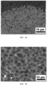
- FIG. 7A is a SEM image of a cross section of a flexible electrode printed with the conductive ink of Example 1.
- FIG. 7B is a SEM image of a cross section of a flexible electrode that is printed with the conductive ink of Example 1 and then undergoes HCl etching.
- FIG. 7C is a SEM image of the upper surface of an electrode when a flexible electrode printed with conductive ink is uniaxially stretched by 500%.
- conductive liquid metal microparticles are vertically stacked on the substrate to increase the contact area between the microparticles and are slightly deformed.
- the conductive liquid metal microparticles are three-dimensionally interconnected through the continuously extending space to form a two-component continuous structure with a PEVA matrix.
- the conductive liquid metal microparticles do not agglomerate and recover to their original shape when the strain is removed even after 1,000 cycles. Such a reversible shape change is allowed due to the elastic property of PEVA. Since the conductive ink of the present invention includes an elastic polymer, when the conductive ink is applied on an elastic polymer substrate (PDMS or Ecoflex) through printing to form a flexible electrode, and the force of deforming the formed flexible electrode is applied, it is confirmed that the flexible electrode dynamically deforms.
- PDMS or Ecoflex elastic polymer substrate
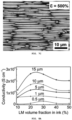
- FIG. 8A illustrates the conductivity according to the size of the liquid metal microparticles of Example 1 and Examples 9 to 12.
- the ultrasonic treatment time was set to 5 minutes, 10 minutes, 15 minutes, 30 minutes, and 120 minutes to control the size of the liquid metal microparticles in the conductive ink.
- the sizes of the liquid metal microparticles were 0.5 um, 1 ⁇ m, 5 ⁇ m, 10 ⁇ m, and 15 ⁇ m, respectively.
- the conductivity of the flexible electrode printed with the conductive ink increases according to the size of the conductive liquid metal microparticles. Specifically, it can be confirmed that the highest conductivity (2,500 Scm -1 ) is achieved when the conductive ink contains conductive liquid metal microparticles with a diameter of 15 um. This is because the contact area between the liquid metal microparticles increases and the number of contacts decreases as the size of the liquid metal microparticles increases.
- the maximum conductivity was obtained when the volume fraction of the conductive liquid metal microparticles was in a range of 20% to 30%, indicating that there is a tradeoff between the content of the liquid metal in the conductive ink and the hydrogen doping efficiency of the liquid metal. It can be confirmed that more liquid metal in the conductive ink results in overall higher conductivity, but hydrogen doping is not enough with a small amount of PEVA.
- FIG. 8B illustrates change in resistance when the flexible electrode printed with the conductive ink of Example 1 is repeatedly uniaxially stretched for 1,000 cycles at strains ( ⁇ ) of 100% and 500%.
- FIG. 8C illustrates a state in which a flexible electrode printed with the conductive ink of Example 1 is connected to an LED and is then uniaxially stretched at various strains.
- the electrode line printed with the conductive ink of Example 1 exhibits a negligible change in resistance while uniaxial stretching is performed for 1,000 cycles at strains ( ⁇ ) of 100% and 500%.
- the graph in FIG. 8B is an enlarged view of resistance change when the flexible electrode printed with the conductive ink of Example 1 is uniaxially stretched 1,000 times at a strain ( ⁇ ) of 500%, and the same resistance curve is shown.
- FIG. 8C shows the change in LED luminance (intensity of light) according to the strain when an LED is attached between two flexible electrodes printed with the conductive ink of Example 1. Referring to FIG. 8C , it is confirmed that the luminance (intensity of light) is constant when the strain ⁇ changes from 0% to 500%.
- FIG. 9A is a photograph of a state in which a flexible electrode formed, through printing, from the conductive ink of Example 1 is scraped with tweezers
- FIG. 9B illustrates resistance change during a period in which a flexible electrode formed, through printing, from the conductive ink of Example 1 is cut with a sharp razor blade.
- FIG. 10 is a SEM image of a cross section of a flexible electrode printed with the conductive ink of Example 14.
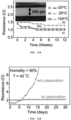
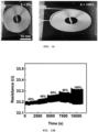
- FIG. 11B shows the resistance change according to the presence and absence of the passivation layer at 40°C and 90% moisture.
- Comparative Example 1 in which a passivation layer is not present, the resistance was not changed for early 4 days, but gradually increased. It is confirmed that the conductivity was lost after 20 days. On the other hand, it was confirmed that the resistance of Example 14 in which the passivation layer is present did not show a change in resistance during the entire measurement period (30 days).
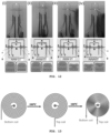
- FIGS. 14 and 15A it is shown that a strain sensor manufactured according to Device Example 2 exhibits a negligible change in resistance even at 100% strain ⁇ , indicating the strain sensor has elasticity.
- the strain sensor manufactured according to Device Example 2 shows a linear response of inductance to deformation. This indicates that the inductance is influenced by the area of the electrode because the resistances of the lower electrode and the upper electrode do not change.
- the conductive liquid metal microparticles can maintain the conductivity without the need of destroying an oxide layer through chemical etching or mechanical scratching.
- the conductive ink of the present invention it is possible to manufacture a flexible electrode maintaining constant conductivity in a wide temperature range and a wide humidity range.
- the conductive ink of the present invention it is possible to manufacture a flexible electrode capable of being formed by 3D circuit printing and a strain sensor including the same electrode.
Landscapes
- Chemical & Material Sciences (AREA)
- Life Sciences & Earth Sciences (AREA)
- Engineering & Computer Science (AREA)
- Materials Engineering (AREA)
- Wood Science & Technology (AREA)
- Organic Chemistry (AREA)
- Chemical Kinetics & Catalysis (AREA)
- General Chemical & Material Sciences (AREA)
- Inks, Pencil-Leads, Or Crayons (AREA)
- Conductive Materials (AREA)
Claims (15)
- Leitfähiges Flüssigmetall-Mikropartikel, das umfasst:einen Kern umfassend ein Flüssigmetall; undeine Hülle, die den Kern umgibt und ein wasserstoffdotiertes Flüssigmetalloxid umfasst.
- Leitfähiges Flüssigmetall-Mikropartikel nach Anspruch 1, wobei die Hülle außerdem ein Flüssigmetalloxid umfasst.
- Leitfähiges Flüssigmetall-Mikropartikel nach Anspruch 1, wobei das wasserstoffdotierte Flüssigmetalloxid durch die chemische Formel 1 dargestellt wird: [Chemische Formel 1] MxOyHz, wobei M ein Flüssigmetall ist, x in einem Bereich von 0<x≤1 liegt, y in einem Bereich von 0<y≤1 liegt und z in einem Bereich von 0<z≤1 liegt.
- Leitfähiges Flüssigmetall-Mikropartikel nach Anspruch 1, wobei das Flüssigmetall mindestens eines, das ausgewählt ist aus der Gruppe bestehend aus Gallium (Ga), Indium (In), Zinn (Sn), Gold (Au) und deren Legierungen, umfasst.
- Leitfähiges Flüssigmetall-Mikropartikel nach Anspruch 1, das außerdem ein elastisches Polymer, das mit der Hülle verbunden und nach außen gerichtet ist, umfasst.
- Leitfähiges Flüssigmetall-Mikropartikel nach Anspruch 5, wobei das elastische Polymer eine Ethylen (-C-C-)-Einheit in einer Kette davon umfasst.
- Leitfähiges Flüssigmetall-Mikropartikel nach Anspruch 5, wobei das elastische Polymer mindestens eines, das ausgewählt ist aus der Gruppe bestehend aus Ethylen-Vinylacetat-Copolymer (PEVA), Styrol-Ethylen-Butylen-Styrol-Blockcopolymer (SEBS) und aliphatischem Polyurethan, umfasst.
- Leitfähiges Flüssigmetall-Mikropartikel nach Anspruch 1, das eine Partikelgröße von 1 bis 10 µm aufweist.
- Leitfähige Tinte, umfassend: ein elastisches Polymer; das leitfähige Flüssigmetall-Mikropartikel nach Anspruch 1; und ein Lösungsmittel.
- Leitfähige Tinte nach Anspruch 9, wobei das elastische Polymer eine Ethylen (-C-C-)-Einheit in einer Kette davon umfasst.
- Leitfähige Tinte nach Anspruch 9, wobei das elastische Polymer mindestens eines, das ausgewählt ist aus der Gruppe bestehend aus Ethylen-Vinylacetat-Copolymer (PEVA), Styrol-Ethylen-Butylen-Styrol-Blockcopolymer (SEBS) und aliphatischem Polyurethan, umfasst.
- Leitfähige Tinte nach Anspruch 9, wobei das Lösungsmittel mindestens eines, das ausgewählt ist aus der Gruppe bestehend aus Toluol, Tetrahydrofuran (THF), Hexan und Heptan, umfasst.
- Leitfähige Tinte nach Anspruch 9, wobei die leitfähige Tinte einen Radikalinitiator umfasst, der Radikalinitiator eine Verbindung auf Peroxidbasis ist und die Verbindung auf Peroxidbasis mindestens eine Verbindung enthält, die aus der Gruppe bestehend aus Dicumylperoxid, Dibenzoylperoxid und Di-tert-butylperoxid ausgewählt ist.
- Verfahren zur Herstellung einer leitfähigen Tinte, wobei das Verfahren umfasst: (a) Herstellen einer gemischten Lösung durch Mischen eines elastischen Polymers, eines Flüssigmetalls, eines Radikalinitiators und eines Lösungsmittels; (b) Ultraschallbehandlung der gemischten Lösung, um eine leitfähige Tinte herzustellen, die die leitfähigen Flüssigmetall-Mikropartikel nach Anspruch 1 enthält.
- Verfahren nach Anspruch 14, wobei Schritt (b) umfasst: (b-1) Ultraschallbehandlung der gemischten Lösung, um zu bewirken, dass das elastische Polymer mit dem Radikalinitiator reagiert, um Wasserstoffradikale (H·) zu erzeugen und einen Kern zu bilden, der das Flüssigmetall enthält; (b-2) Oxidieren des Flüssigmetalls auf der Oberfläche des Kerns, um ein Flüssigmetalloxid zu bilden, das den Kern umgibt; und (b-3) Bilden von leitfähigen Flüssigmetall-Mikropartikeln, die jeweils eine Hülle aufweisen, die ein wasserstoffdotiertes Flüssigmetalloxid enthält, das durch Bindung des Wasserstoffradikals (H·) und Sauerstoff des Flüssigmetalloxids gebildet wird.
Applications Claiming Priority (2)
| Application Number | Priority Date | Filing Date | Title |
|---|---|---|---|
| KR1020200033237A KR102290112B1 (ko) | 2020-03-18 | 2020-03-18 | 수소 도핑된 액체금속 산화물을 포함하는 전도성 액체금속 미세입자, 그를 포함하는 전도성 잉크 및 그의 제조방법 |
| PCT/KR2020/018245 WO2021187724A1 (ko) | 2020-03-18 | 2020-12-14 | 수소 도핑된 액체금속 산화물을 포함하는 전도성 액체금속 미세입자, 그를 포함하는 전도성 잉크 및 그의 제조방법 |
Publications (3)
| Publication Number | Publication Date |
|---|---|
| EP4122989A1 EP4122989A1 (de) | 2023-01-25 |
| EP4122989A4 EP4122989A4 (de) | 2024-04-03 |
| EP4122989B1 true EP4122989B1 (de) | 2025-02-05 |
Family
ID=77313829
Family Applications (1)
| Application Number | Title | Priority Date | Filing Date |
|---|---|---|---|
| EP20925809.4A Active EP4122989B1 (de) | 2020-03-18 | 2020-12-14 | Leitfähige flüssige metallmikroteilchen, die wasserstoffdotiertes flüssiges metalloxid umfassen, leitfähige tinte, die diese umfasst, und herstellungsverfahren dafür |
Country Status (4)
| Country | Link |
|---|---|
| US (1) | US12180381B2 (de) |
| EP (1) | EP4122989B1 (de) |
| KR (1) | KR102290112B1 (de) |
| WO (1) | WO2021187724A1 (de) |
Families Citing this family (9)
| Publication number | Priority date | Publication date | Assignee | Title |
|---|---|---|---|---|
| CN113897096A (zh) * | 2021-09-27 | 2022-01-07 | 武汉大学 | 一种基于液态金属-微米金属片的超拉伸材料用导电印刷墨水及其应用 |
| CN116836588B (zh) * | 2022-03-23 | 2025-03-11 | 东南大学 | 一种导电墨水及其制备方法 |
| KR102557855B1 (ko) * | 2022-07-20 | 2023-07-24 | 한국과학기술원 | 액체금속 용액, 이를 포함하는 잉크 및 이를 포함하는 전자소자 |
| KR102788478B1 (ko) * | 2022-10-04 | 2025-04-01 | 광주과학기술원 | 액체 금속 나노입자-공액고분자 복합체를 포함하는 전도성 수성 잉크 및 이의 제조방법 |
| CN116023824B (zh) * | 2023-01-18 | 2023-09-01 | 上海宇叠智能科技有限公司 | 导电油墨及其制备方法和应用 |
| CN116574212B (zh) * | 2023-03-23 | 2024-07-19 | 厦门大学 | 一种聚合物/液态金属复合导电固体材料及其制备方法 |
| CN116694141B (zh) * | 2023-06-28 | 2025-03-04 | 香港中文大学(深圳) | 一种可打印的液态金属墨水及其制备方法 |
| KR20250125834A (ko) * | 2024-02-15 | 2025-08-22 | 성균관대학교산학협력단 | 액체금속-자성입자를 포함하는 고분자 복합재 |
| KR20250175988A (ko) | 2024-06-11 | 2025-12-18 | 한양대학교 산학협력단 | 액체금속 입자-유기전자수용체 화합물 복합체, 이를 포함하는 필름 및 유연 전극 |
Family Cites Families (9)
| Publication number | Priority date | Publication date | Assignee | Title |
|---|---|---|---|---|
| CN105103239B (zh) * | 2013-01-23 | 2019-09-10 | 汉高知识产权控股有限责任公司 | 柔性导电油墨 |
| US10293325B2 (en) * | 2013-12-11 | 2019-05-21 | University Of Massachusetts | Core-shell multi-layer particles |
| KR101779665B1 (ko) * | 2015-08-28 | 2017-09-19 | 전자부품연구원 | 전도성 고분자 조성물 및 그의 제조방법 |
| US9859226B1 (en) * | 2016-12-13 | 2018-01-02 | International Business Machines Corporation | Core-shell particles for anti-tampering applications |
| KR101890888B1 (ko) * | 2017-02-09 | 2018-08-22 | 울산과학기술원 | 탄소-공융 갈륨 인듐 복합체, 그 제조방법, 및 이를 포함한 전극 재료 |
| WO2018194517A1 (en) * | 2017-04-18 | 2018-10-25 | Nanyang Technological University | Elastic conductor, device including, and method of forming the same |
| WO2019055680A1 (en) | 2017-09-13 | 2019-03-21 | Carnegie Mellon University | LIQUID METAL FUSION WITH INKS AND CONDUCTIVE PASTES |
| KR101993813B1 (ko) * | 2017-12-11 | 2019-06-27 | 울산과학기술원 | 상온 액체금속 캡슐 잉크, 그 제조 방법, 및 이를 이용하여 형성한 상온 액체금속 캡슐 배선 |
| KR101993812B1 (ko) * | 2017-12-11 | 2019-06-27 | 울산과학기술원 | 상온 액체금속 캡슐 및 그 제조 방법 |
-
2020
- 2020-03-18 KR KR1020200033237A patent/KR102290112B1/ko active Active
- 2020-12-14 EP EP20925809.4A patent/EP4122989B1/de active Active
- 2020-12-14 WO PCT/KR2020/018245 patent/WO2021187724A1/ko not_active Ceased
- 2020-12-14 US US17/781,117 patent/US12180381B2/en active Active
Also Published As
| Publication number | Publication date |
|---|---|
| KR102290112B1 (ko) | 2021-08-13 |
| US12180381B2 (en) | 2024-12-31 |
| US20240199903A1 (en) | 2024-06-20 |
| EP4122989A1 (de) | 2023-01-25 |
| WO2021187724A1 (ko) | 2021-09-23 |
| EP4122989A4 (de) | 2024-04-03 |
Similar Documents
| Publication | Publication Date | Title |
|---|---|---|
| EP4122989B1 (de) | Leitfähige flüssige metallmikroteilchen, die wasserstoffdotiertes flüssiges metalloxid umfassen, leitfähige tinte, die diese umfasst, und herstellungsverfahren dafür | |
| US11974393B2 (en) | Flexible electrode circuit capable of being 3D circuit printed strain sensor using same, and manufacturing method therefor | |
| Arjmand et al. | Outstanding electromagnetic interference shielding of silver nanowires: comparison with carbon nanotubes | |
| KR102719657B1 (ko) | 무소결 액체금속 잉크의 제조방법 | |
| CN108275683B (zh) | 一种金属基复合材料及其制备方法和用途 | |
| Zhang et al. | PVP-mediated galvanic replacement synthesis of smart elliptic Cu–Ag nanoflakes for electrically conductive pastes | |
| US9460828B2 (en) | Graphene printed pattern circuit structure | |
| EP3056547B1 (de) | Leitfähiges material und wandler damit | |
| US10550291B2 (en) | Core-shell, oxidation-resistant, electrically conducting particles for low temperature conductive applications | |
| KR102247841B1 (ko) | 그래핀층을 포함하는 방열 및 차폐용 복합시트 | |
| US20180327543A1 (en) | Highly stretchable, transparent, and conductive polymer | |
| KR102647120B1 (ko) | 도전성 입자, 도전 재료 및 접속 구조체 | |
| US12046572B2 (en) | Bonding sheet and bonded structure | |
| KR20170053462A (ko) | 금속 산화물 나노시트들의 집단과 그 제조 방법, 및 이를 포함하는 도전체 및 전자 소자 | |
| KR20200140809A (ko) | 절연성 입자를 갖는 도전성 입자, 도전 재료 및 접속 구조체 | |
| EP3159896B1 (de) | Stromleiter, verfahren zur herstellung davon und elektronische vorrichtungen damit | |
| US11661346B2 (en) | Functionally graded all-graphene based free-standing materials, methods of making and uses thereof | |
| JP6237098B2 (ja) | 分散剤、導電性基板用金属粒子分散体、及び導電性基板の製造方法 | |
| Cao et al. | Synthesis of citrate-capped Sn nanoparticles with excellent oxidation resistance for high-performance electrically conductive adhesives | |
| Paul et al. | Synthesis and characterization of epoxy-aluminum nanocomposites for energy storage applications | |
| TWI768068B (zh) | 導電性粒子、導電性粒子之製造方法、導電材料及連接構造體 | |
| JP2012174375A (ja) | 導電性塗膜の製造方法及び導電性塗膜 | |
| US12581629B2 (en) | Electromagnetic shielding composition containing morphologically different metals | |
| US20250250453A1 (en) | Systems, Devices, and Methods for Making and Using Printable Copper-Based Metal and Intermetallic Ink Materials | |
| KR101366758B1 (ko) | 전자흡인기를 함유하는 고분자를 포함하는 그래핀 적층체 및 그 제조방법 |
Legal Events
| Date | Code | Title | Description |
|---|---|---|---|
| STAA | Information on the status of an ep patent application or granted ep patent |
Free format text: STATUS: THE INTERNATIONAL PUBLICATION HAS BEEN MADE |
|
| PUAI | Public reference made under article 153(3) epc to a published international application that has entered the european phase |
Free format text: ORIGINAL CODE: 0009012 |
|
| STAA | Information on the status of an ep patent application or granted ep patent |
Free format text: STATUS: REQUEST FOR EXAMINATION WAS MADE |
|
| 17P | Request for examination filed |
Effective date: 20220518 |
|
| AK | Designated contracting states |
Kind code of ref document: A1 Designated state(s): AL AT BE BG CH CY CZ DE DK EE ES FI FR GB GR HR HU IE IS IT LI LT LU LV MC MK MT NL NO PL PT RO RS SE SI SK SM TR |
|
| DAV | Request for validation of the european patent (deleted) | ||
| DAX | Request for extension of the european patent (deleted) | ||
| A4 | Supplementary search report drawn up and despatched |
Effective date: 20240228 |
|
| RIC1 | Information provided on ipc code assigned before grant |
Ipc: C09D 11/106 20140101ALI20240223BHEP Ipc: C09D 11/102 20140101ALI20240223BHEP Ipc: C09D 11/037 20140101ALI20240223BHEP Ipc: C09D 11/033 20140101ALI20240223BHEP Ipc: C09D 11/03 20140101ALI20240223BHEP Ipc: C09D 11/10 20140101ALI20240223BHEP Ipc: C09D 11/52 20140101AFI20240223BHEP |
|
| RIC1 | Information provided on ipc code assigned before grant |
Ipc: H01B 1/02 20060101ALI20240815BHEP Ipc: C09D 11/106 20140101ALI20240815BHEP Ipc: C09D 11/102 20140101ALI20240815BHEP Ipc: C09D 11/037 20140101ALI20240815BHEP Ipc: C09D 11/033 20140101ALI20240815BHEP Ipc: C09D 11/03 20140101ALI20240815BHEP Ipc: C09D 11/10 20140101ALI20240815BHEP Ipc: C09D 11/52 20140101AFI20240815BHEP |
|
| GRAP | Despatch of communication of intention to grant a patent |
Free format text: ORIGINAL CODE: EPIDOSNIGR1 |
|
| STAA | Information on the status of an ep patent application or granted ep patent |
Free format text: STATUS: GRANT OF PATENT IS INTENDED |
|
| INTG | Intention to grant announced |
Effective date: 20240923 |
|
| GRAS | Grant fee paid |
Free format text: ORIGINAL CODE: EPIDOSNIGR3 |
|
| GRAA | (expected) grant |
Free format text: ORIGINAL CODE: 0009210 |
|
| STAA | Information on the status of an ep patent application or granted ep patent |
Free format text: STATUS: THE PATENT HAS BEEN GRANTED |
|
| AK | Designated contracting states |
Kind code of ref document: B1 Designated state(s): AL AT BE BG CH CY CZ DE DK EE ES FI FR GB GR HR HU IE IS IT LI LT LU LV MC MK MT NL NO PL PT RO RS SE SI SK SM TR |
|
| REG | Reference to a national code |
Ref country code: GB Ref legal event code: FG4D |
|
| REG | Reference to a national code |
Ref country code: CH Ref legal event code: EP |
|
| REG | Reference to a national code |
Ref country code: DE Ref legal event code: R096 Ref document number: 602020045775 Country of ref document: DE |
|
| REG | Reference to a national code |
Ref country code: IE Ref legal event code: FG4D |
|
| REG | Reference to a national code |
Ref country code: NL Ref legal event code: MP Effective date: 20250205 |
|
| PG25 | Lapsed in a contracting state [announced via postgrant information from national office to epo] |
Ref country code: RS Free format text: LAPSE BECAUSE OF FAILURE TO SUBMIT A TRANSLATION OF THE DESCRIPTION OR TO PAY THE FEE WITHIN THE PRESCRIBED TIME-LIMIT Effective date: 20250505 |
|
| PG25 | Lapsed in a contracting state [announced via postgrant information from national office to epo] |
Ref country code: FI Free format text: LAPSE BECAUSE OF FAILURE TO SUBMIT A TRANSLATION OF THE DESCRIPTION OR TO PAY THE FEE WITHIN THE PRESCRIBED TIME-LIMIT Effective date: 20250205 |
|
| PG25 | Lapsed in a contracting state [announced via postgrant information from national office to epo] |
Ref country code: PL Free format text: LAPSE BECAUSE OF FAILURE TO SUBMIT A TRANSLATION OF THE DESCRIPTION OR TO PAY THE FEE WITHIN THE PRESCRIBED TIME-LIMIT Effective date: 20250205 |
|
| PG25 | Lapsed in a contracting state [announced via postgrant information from national office to epo] |
Ref country code: ES Free format text: LAPSE BECAUSE OF FAILURE TO SUBMIT A TRANSLATION OF THE DESCRIPTION OR TO PAY THE FEE WITHIN THE PRESCRIBED TIME-LIMIT Effective date: 20250205 |
|
| REG | Reference to a national code |
Ref country code: LT Ref legal event code: MG9D |
|
| PG25 | Lapsed in a contracting state [announced via postgrant information from national office to epo] |
Ref country code: IS Free format text: LAPSE BECAUSE OF FAILURE TO SUBMIT A TRANSLATION OF THE DESCRIPTION OR TO PAY THE FEE WITHIN THE PRESCRIBED TIME-LIMIT Effective date: 20250605 Ref country code: NO Free format text: LAPSE BECAUSE OF FAILURE TO SUBMIT A TRANSLATION OF THE DESCRIPTION OR TO PAY THE FEE WITHIN THE PRESCRIBED TIME-LIMIT Effective date: 20250505 |
|
| PG25 | Lapsed in a contracting state [announced via postgrant information from national office to epo] |
Ref country code: NL Free format text: LAPSE BECAUSE OF FAILURE TO SUBMIT A TRANSLATION OF THE DESCRIPTION OR TO PAY THE FEE WITHIN THE PRESCRIBED TIME-LIMIT Effective date: 20250205 |
|
| PG25 | Lapsed in a contracting state [announced via postgrant information from national office to epo] |
Ref country code: HR Free format text: LAPSE BECAUSE OF FAILURE TO SUBMIT A TRANSLATION OF THE DESCRIPTION OR TO PAY THE FEE WITHIN THE PRESCRIBED TIME-LIMIT Effective date: 20250205 |
|
| PG25 | Lapsed in a contracting state [announced via postgrant information from national office to epo] |
Ref country code: LV Free format text: LAPSE BECAUSE OF FAILURE TO SUBMIT A TRANSLATION OF THE DESCRIPTION OR TO PAY THE FEE WITHIN THE PRESCRIBED TIME-LIMIT Effective date: 20250205 Ref country code: PT Free format text: LAPSE BECAUSE OF FAILURE TO SUBMIT A TRANSLATION OF THE DESCRIPTION OR TO PAY THE FEE WITHIN THE PRESCRIBED TIME-LIMIT Effective date: 20250605 |
|
| PG25 | Lapsed in a contracting state [announced via postgrant information from national office to epo] |
Ref country code: GR Free format text: LAPSE BECAUSE OF FAILURE TO SUBMIT A TRANSLATION OF THE DESCRIPTION OR TO PAY THE FEE WITHIN THE PRESCRIBED TIME-LIMIT Effective date: 20250506 Ref country code: BG Free format text: LAPSE BECAUSE OF FAILURE TO SUBMIT A TRANSLATION OF THE DESCRIPTION OR TO PAY THE FEE WITHIN THE PRESCRIBED TIME-LIMIT Effective date: 20250205 |
|
| REG | Reference to a national code |
Ref country code: AT Ref legal event code: MK05 Ref document number: 1764889 Country of ref document: AT Kind code of ref document: T Effective date: 20250205 |
|
| PG25 | Lapsed in a contracting state [announced via postgrant information from national office to epo] |
Ref country code: SE Free format text: LAPSE BECAUSE OF FAILURE TO SUBMIT A TRANSLATION OF THE DESCRIPTION OR TO PAY THE FEE WITHIN THE PRESCRIBED TIME-LIMIT Effective date: 20250205 |
|
| PG25 | Lapsed in a contracting state [announced via postgrant information from national office to epo] |
Ref country code: SM Free format text: LAPSE BECAUSE OF FAILURE TO SUBMIT A TRANSLATION OF THE DESCRIPTION OR TO PAY THE FEE WITHIN THE PRESCRIBED TIME-LIMIT Effective date: 20250205 |
|
| PG25 | Lapsed in a contracting state [announced via postgrant information from national office to epo] |
Ref country code: DK Free format text: LAPSE BECAUSE OF FAILURE TO SUBMIT A TRANSLATION OF THE DESCRIPTION OR TO PAY THE FEE WITHIN THE PRESCRIBED TIME-LIMIT Effective date: 20250205 |
|
| PG25 | Lapsed in a contracting state [announced via postgrant information from national office to epo] |
Ref country code: IT Free format text: LAPSE BECAUSE OF FAILURE TO SUBMIT A TRANSLATION OF THE DESCRIPTION OR TO PAY THE FEE WITHIN THE PRESCRIBED TIME-LIMIT Effective date: 20250205 |
|
| PG25 | Lapsed in a contracting state [announced via postgrant information from national office to epo] |
Ref country code: AT Free format text: LAPSE BECAUSE OF FAILURE TO SUBMIT A TRANSLATION OF THE DESCRIPTION OR TO PAY THE FEE WITHIN THE PRESCRIBED TIME-LIMIT Effective date: 20250205 |
|
| PGFP | Annual fee paid to national office [announced via postgrant information from national office to epo] |
Ref country code: FR Payment date: 20250925 Year of fee payment: 6 |
|
| PG25 | Lapsed in a contracting state [announced via postgrant information from national office to epo] |
Ref country code: EE Free format text: LAPSE BECAUSE OF FAILURE TO SUBMIT A TRANSLATION OF THE DESCRIPTION OR TO PAY THE FEE WITHIN THE PRESCRIBED TIME-LIMIT Effective date: 20250205 Ref country code: CZ Free format text: LAPSE BECAUSE OF FAILURE TO SUBMIT A TRANSLATION OF THE DESCRIPTION OR TO PAY THE FEE WITHIN THE PRESCRIBED TIME-LIMIT Effective date: 20250205 |
|
| PG25 | Lapsed in a contracting state [announced via postgrant information from national office to epo] |
Ref country code: RO Free format text: LAPSE BECAUSE OF FAILURE TO SUBMIT A TRANSLATION OF THE DESCRIPTION OR TO PAY THE FEE WITHIN THE PRESCRIBED TIME-LIMIT Effective date: 20250205 |
|
| PG25 | Lapsed in a contracting state [announced via postgrant information from national office to epo] |
Ref country code: SK Free format text: LAPSE BECAUSE OF FAILURE TO SUBMIT A TRANSLATION OF THE DESCRIPTION OR TO PAY THE FEE WITHIN THE PRESCRIBED TIME-LIMIT Effective date: 20250205 |
|
| REG | Reference to a national code |
Ref country code: DE Ref legal event code: R097 Ref document number: 602020045775 Country of ref document: DE |
|
| PLBE | No opposition filed within time limit |
Free format text: ORIGINAL CODE: 0009261 |
|
| STAA | Information on the status of an ep patent application or granted ep patent |
Free format text: STATUS: NO OPPOSITION FILED WITHIN TIME LIMIT |
|
| PGFP | Annual fee paid to national office [announced via postgrant information from national office to epo] |
Ref country code: DE Payment date: 20250922 Year of fee payment: 6 |
|
| 26N | No opposition filed |
Effective date: 20251106 |