EP4122364B1 - Vorrichtung zur reinigung von jalousien - Google Patents
Vorrichtung zur reinigung von jalousien Download PDFInfo
- Publication number
- EP4122364B1 EP4122364B1 EP21186663.7A EP21186663A EP4122364B1 EP 4122364 B1 EP4122364 B1 EP 4122364B1 EP 21186663 A EP21186663 A EP 21186663A EP 4122364 B1 EP4122364 B1 EP 4122364B1
- Authority
- EP
- European Patent Office
- Prior art keywords
- bristle
- pair
- fluid
- cleaning device
- blind
- Prior art date
- Legal status (The legal status is an assumption and is not a legal conclusion. Google has not performed a legal analysis and makes no representation as to the accuracy of the status listed.)
- Active
Links
Images



Classifications
-
- A—HUMAN NECESSITIES
- A47—FURNITURE; DOMESTIC ARTICLES OR APPLIANCES; COFFEE MILLS; SPICE MILLS; SUCTION CLEANERS IN GENERAL
- A47L—DOMESTIC WASHING OR CLEANING; SUCTION CLEANERS IN GENERAL
- A47L4/00—Cleaning window shades, window screens, venetian blinds
- A47L4/02—Hand implements for cleaning venetian blinds
Definitions
- the present disclosure relates to a blind cleaning device.
- Window blinds are commonly installed in various spaces, such as commercial buildings or a residential space as part of an interior decoration of such spaces.
- the window blinds are used to regulate an amount of desired light in the space where they are installed. Further, the window blinds may block direct sunlight, promote energy conservation, and provide privacy.
- the window blinds typically consist of multiple lamellae that are arranged in parallel.
- the lamellae are spaced apart from each other by a predefined distance.
- a number of controlling means are provided for controlling an angular position of the lamellae of the window blinds, such that the lamellae may be angularly rotated between an open position, which permits maximum passage of light through the window blinds, and a closed position, which provides maximum blockage of light through the window blinds.
- dirt, dust, debris, particulate matter, and the like may accumulate on the window blinds.
- pathogens may also be present on the window blinds.
- such window blinds may have to be periodically cleaned. In applications where a large number of window blinds are installed, such as in the commercial buildings, individual cleaning of each lamella becomes a time consuming and laborious task.
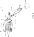
- FIG. 1 is a perspective view of a blind cleaning device 100.
- the blind cleaning device 100 may be used for different cleaning applications, such as to clean a number of lamellae (not shown) of a window blind (not shown).
- the present disclosure illustrates a cleaning device as the blind cleaning device 100, however actual implementation of the present disclosure may be applied with any cleaning device making use of one or more brushes, bristles and the like.
- the blind cleaning device 100 includes a body 102 defining a bracket 104.
- the body 102 may be manufactured from a plastic, a metal, and the like.
- the body 102 may be embodied as a single piece unit or the body 102 may include multiple separate parts that are joined together to form the body 102.
- the body 102 may be coupled with different types of cleaning attachments, such as, brushes, showers, nozzle, and the like.
- the body 102 is coupled with a fluid connection 103 which provides a fluid towards the blind cleaning device 100.
- the fluid connection may include a tap, pump, and the like. Further, the fluid may include water or any other cleaning fluid.
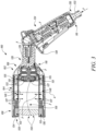
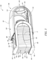
- FIG. 3 shows the blind cleaning device 100, in accordance with an embodiment of the present disclosure.
- the body 102 includes a distributor 127.
- the distributor 127 defines a T-shaped structure, although other shapes, types, dimensions, structure have been contemplated and are well within the scope.
- the distributor 127 includes an inlet channel 129 and two outlet channels 131.
- the outlet channels 131 are substantially perpendicular to the inlet channel 129.
- the inlet channel 129 is fluidly coupled to the inlet portion 118 of the body 102 for a fluid flow "F" (or simply the fluid), such as water for cleaning, therethrough.
- F fluid flow
- the present disclosure refers to the "fluid” or the “fluid flow” which have been used interchangeably for ease of explanation and understanding.
- the fluid flow “F” through the blind cleaning device 100 is illustrated in FIG. 3 for detail flow from a hose connector 130 to a fluid supply device 124, and then to the distributor 127 of the body 102. This fluid flow “F” then splits in the distributor 127 to move towards each bristle plate 134, 136, as illustrated in FIG. 3 .
- the body 102 also includes an adjustable limitation stop 122 (shown in FIG. 3 ) for different lamella width.
- the limitation stop 122 may be integrated and work with the distributor 127 to allow splitting of the fluid i.e., water from the inlet channel 129 to the outlet channels 131.
- the blind cleaning device 100 may not include any limitation stop 122 and make application of the distributor 127.
- a connecting portion 142 (shown in FIG. 4 ) includes the adjustable limitation stop 122.
- the limitation stop 122 includes a cylindrical body defining an inlet (not shown) and an outlet (not shown). The inlet is fluidly coupled to the inlet portion 118 of the body 102 to supply fluid, such as water for cleaning, therethrough.
- the limitation stop 122 may accommodate a jet that allows discharge of fluid therethrough. Further, the limitation stop 122 can be adjusted for different lamella width. In some examples, the limitation stop 122 can be adjusted to accommodate the lamella width that approximately lies in a range of about 40 Millimeters (mm) to about 100 mm.
- the jet may be flat or conical. The limitation stop 122 may be adjusted to obtain different types of fluid jet, such as flat fluid jet, conical fluid jet, and the like. Specifically, the limitation stop 122 can be rotated to adjust a pattern of the jet.
- the body 102 is removably coupled with the fluid supply device 124 for supply of the fluid. The inlet portion 118 of the body 102 allows removable coupling of the body 102 with the fluid supply device 124 using a rotatable joint 126.
- the blind cleaning device 100 also includes the fluid supply device 124.
- the fluid supply device 124 includes an actuator 128 to allow passage of the fluid towards the body 102 of the blind cleaning device 100. When actuated, the actuator 128 allows passage of fluid therethrough.
- the fluid supply device 124 may include any arrangement for passage of the fluid towards the body 102 of the blind cleaning device 100, such as a button, a knob, a handle, and the like.
- the fluid supply device 124 includes a first inlet 116 and a first outlet 120.
- the hose connector 130 is removably attached to the fluid supply device 124.
- the hose connector 130 is removably attached to the first inlet 116 of the fluid supply device 124.
- the hose connector 130 includes a threaded section 132 to removably couple a hose pipe (not shown) with the hose connector 130.
- the hose pipe may supply the fluid from the fluid connection 103 towards the blind cleaning device 100.
- the blind cleaning device 100 includes the rotatable joint 126 between the body 102 and the fluid supply device 124.
- the rotatable joint 126 includes a cylindrical body, a joint inlet (not shown), and a joint outlet (not shown).
- the joint inlet is connected to the fluid supply device 124 and the joint outlet is removably coupled with the inlet portion 118 of the body 102.
- the joint outlet may be partially received through the through-holes 144.
- the joint outlet may include a threaded section (not shown) for removable coupling with the inlet portion 118 of the body 102.
- the rotatable joint 126 allows coupling of the body 102 of the blind cleaning device 100 with the fluid supply device 124 at various angles.
- the rotatable joint 126 between the body 102 and the fluid supply device 124 provides improved ergonomics during cleaning, such as of a soil-deep window (not shown).
- the rotatable joint 126 In a first position or a vertical position, as illustrated in FIGS. 1 to 3 , the rotatable joint 126 allows vertical coupling of the fluid supply device 124 with the body 102 of the blind cleaning device 100. The first position of the fluid supply device 124 may create less disturbance for the user during the cleaning operation. Referring to FIG. 4 , in a second position or a horizontal position, the rotatable joint 126 allows horizontal coupling of the fluid supply device 124 with the body 102 of the blind cleaning device 100. In the second position of the fluid supply device 124, the user may feel less weight during a cleaning operation.
- first/vertical and the second/horizontal positions of the rotatable joint 126 may allow different positions, angles, ergonomic styles for cleaning by the body 102 of the blind cleaning device 100. Further, the present disclosure illustrates and discusses the first/vertical and the second/horizontal positions, however actual implementation may have many and other positions in between the first/vertical and the second/horizontal positions of the rotatable joint 126.
- the blind cleaning device 100 also includes a pair of bristle plates 134, 136 to couple with the bracket 104 of the body 102.
- the blind cleaning device 100 includes the first bristle plate 134 and the second bristle plate 136 facing the first bristle plate 134 and spaced apart from the first bristle plate 134.
- the pair of bristle plates 134, 136 may be similar in shape and size. Alternatively, the bristle plates 134, 136 may include different shape and size.
- the bristle plate 134, 136 defines a first plate surface 138 and a second plate surface 140.
- the first plate surface 138 of the bristle plate 134, 136 includes a generally planar profile.
- the first plate surface 138 includes a number receiving slots 146 to receive the projections 114 of the bracket 104.
- the second plate surface 140 of the bristle plates 134, 136 includes a curved profile.
- the pair of bristle plates 134, 136 may be coupled to the bracket 104 using a snap-fit connection. It should be noted that the pair of bristle plates 134, 136 and the bracket 104 may be connected by any other means, without limiting the scope of the present disclosure.
- the pair of bristle plates 134, 136 are connected with each other by the connecting portion 142.
- the pair of bristle plates 134, 136 and the connecting portion 142 are embodied as an integral unit.
- the pair of bristle plates 134, 136 and the connecting portion 142 may be embodied as separate parts that are joined together.
- the pair of bristle plates 134, 136 and the connecting portion 142 form a generally U-shaped structure.
- the pair of bristle plates 134, 136 are substantially parallel and include a spring-loaded mechanism (not shown).
- the spring-loaded mechanism of the bristle plates 134, 136 may allow some adjustment or movements thereof, and may exert a pressure on the lamella of the window blinds to effectively clean dirt particles from a surface of the lamella. Further, the spring-loaded mechanism and the fluid jet may allow efficient cleaning of greasy residue on the lamella surface.
- the blind cleaning device 100 further includes a pair of bristle brushes 150 coupled with the pair of the bristle plates 134, 136.
- the pair of bristle brushes 150 are disposed on the second plate surface 140 and extend therefrom.
- Each of the pair of bristle brushes 150 includes the plurality of bristles 152.
- the pair of bristles 152 of the pair of bristle brushes 150 overlap each other.
- the bristles 152 may be tilted and arranged in a shape 154 to suit the shape of the lamellae of the window blind. This arrangement may allow uniform cleaning of the lamella surface.
- each bristle plate 134, 136 may include a bristle fixation element 155 (as shown in FIG. 3 ) to removably couple the pair of bristle brushes 150.
- the bristle fixation element 155 can be removably coupled to the bristle plates 134, 136.
- the bristle fixation element 155 may be made up of a soft plastic material. The bristle fixation element 155 allows removable coupling of the pair of bristle brushes 150 with the bristle plates 134, 136.
- each bristle brush 134, 136 may be manufactured using a synthetic material, such as nylon. It should be noted that the bristles 152 may include any other material, without limiting the scope of the present invention.
- FIGS. 6A and 6B different views of the blind cleaning device 100 is illustrated.
- at least one of the pair of bristle plates 134, 136 define one or more openings 148 to allow discharge of the fluid therefrom.
- the one or more openings 148 are specifically provided to allow discharge or drainage of any excess amount or flow of the fluid during application of the blind cleaning device 100. Such discharge or drainage of the fluid will take place, through the one or more openings 148, substantially perpendicular to the first and second bristle plates 134, 136 leading to a simple, user-friendly, and splash-proof cleaning application by the blind cleaning device 100.
- each of the first and second bristle plates 134, 136 includes the opening 148.
- any one of the first and second bristle plates 134, 136 may include the opening 148.
- the openings 148 of each bristle plate 134, 136 may be identical in shape and size.
- the openings 148 are centrally disposed within the bristle plates 134, 136, however, actual implementations may have any position, type, size, placement, or number of the openings 148.
- the fluid jet directed through the distributor 127 may split through the distributor 127 to discharge the fluid from the openings 148 provided on the bristle plates 134, 136 after cleaning the lamella surface.
- the pair of bristle brushes 150 are coupled with the pair of the bristle plates 134, 136 such that the pair of bristle brushes 150 contact each other to define a cleaning room 156 (shown in FIG. 6B ) with the pair of the bristle plates 134, 136.
- the pair of bristle brushes 150 overlap each other, such that minimum efforts may be required to clean the lamella, and there may not be any undesired fluid spillage through or around the pair of bristle brushes 150.
- the fluid connection supplies the fluid into the cleaning room 156.
- the cleaning room 156 defines an axis "A" (shown in FIG. 3 ) normal to each opening 148 of the bristle plates 134, 136.
- the cleaning room 156 may allow removal or discharge of the fluid (say water) therethrough. Particularly, the cleaning room 156 may allow the fluid to discharge along the axis "A" therethrough, to check or avoid any undesired splashing or movement of the fluid substantially perpendicular to the axis "A". Moreover, the arrangement of bristles 152 and the cleaning room 156 avoids splashing of fluid during cleaning process. Further, a front side 158 of the pair of bristle brushes 150 may be covered with a textile material, a rubber material, a plastic sheet, a foil sheet, and the like, for additional protection against the splashing of fluid.
- the cleaning room 156 of the present disclosure is defined between the pair of the bristle plates 134, 136 and the pair of bristle brushes 150. This may create a rectangular, square or any other geometrical shaped volume of the cleaning room 156, which allows to receive and hold the fluid during cleaning by the blind cleaning device 100. Further, the cleaning room 156 may allow discharge of the fluid through the opening 148, while avoiding any undesired spillage or discharge of the liquid through or around the pair of bristle brushes 150.
- the pair of bristle plates 134, 136 is height adjustable to change a distance "D" between the pair of bristle plates 134, 136.
- the height adjustable bristle plates 134, 136 may be used to adjust the distance "D" between the pair of bristle plates 134, 136 when the plurality of bristles 152 of the pair of bristle brushes 150 wear out. More particularly, in an event of wear out of the bristles 152, the bristle plates 134, 136 may be disposed closer to each other to compensate for a reduction in a length of the bristles 152. This height adjustable nature of the bristle plates 134, 136 may be due to the spring-loaded mechanism.
- the height adjustable nature of the pair of bristle plates 134, 136 may allow to change the distance "D" and thereby change dimensions (i.e. volume) of the cleaning room 156.
- Such change in the dimensions of the cleaning room 156 may be suitable for different applications or operational requirements, such as to control a rate of the fluid leaving the cleaning room 156 (say along the axis "A").
- the bracket 104 of the blind cleaning device 100 may include a rectangular shape with rounded corners instead of the U-shaped structure.
- each bristle plate 134, 136 may be directly coupled with the rectangular bracket 104 using a number of mechanical fasteners and the connecting portion 142 may be omitted.
- the present disclosure provides the improved blind cleaning device 100 to clean the lamellae of window blinds effectively and efficiently.
- the blind cleaning device 100 allows cleaning of the window blinds with or without fluid. Further, the blind cleaning device 100 allows removable coupling of different attachments, such as brushes, showers, nozzle, and the like.
- the blind cleaning device 100 includes fewer parts and can be easily assembled without requiring additional tools. Further, the blind cleaning device 100 is easy and convenient to use for users and does not cause user fatigue.
Landscapes
- Cleaning Implements For Floors, Carpets, Furniture, Walls, And The Like (AREA)
- Brushes (AREA)
- Blinds (AREA)
Claims (9)
- Eine Jalousienreinigungsvorrichtung (100), die Folgendes umfasst:einen Körper (102), der einen Halterung (104) bildet;ein Paar von Borstenplatten (134, 136), die mit der Halterung (104) des Körpers (102) koppelbar sind, wobei der Körper (102) mit einem Fluidanschluss (103) koppelbar ist, der ein Fluid bereitstellt; undein Paar von Borstenbürsten (150), die dazu geeignet sind, mit dem Paar von Borstenplatten (134, 136) zu koppeln, wobei jede des Paars von Borstenbürsten (150) eine Vielzahl von Borsten (152) umfasst;dadurch gekennzeichnet, dass:
das Paar von Borstenbürsten (150) mit dem Paar von Borstenplatten (134, 136) gekoppelt ist, so dass das Paar von Borstenbürsten (150) einander berührt, um einen Reinigungsraum (156) mit dem Paar von Borstenplatten (134, 136) zu definieren, wobei die Fluidverbindung (103) das Fluid in den Reinigungsraum (156) liefert. - Die Jalousiereinigungsvorrichtung (100) nach Anspruch 1, wobei der Körper (102) abnehmbar mit einer Fluidzufuhrvorrichtung (124) für die Zufuhr des Fluids gekoppelt ist.
- Die Jalousiereinigungsvorrichtung (100) nach Anspruch 2, wobei die Jalousiereinigungsvorrichtung eine drehbare Verbindung (126) zwischen dem Körper (102) und der Fluidzufuhrvorrichtung (124) aufweist.
- Die Jalousiereinigungsvorrichtung (100) nach Anspruch 2 oder 3, wobei ein Schlauchanschluss (130) abnehmbar an der Fluidzufuhrvorrichtung (124) angebracht ist.
- Die Jalousiereinigungsvorrichtung (100) nach Anspruch 1, wobei mindestens eine des Paars von Borstenplatten (134, 136) eine oder mehrere Öffnungen (148) definiert, um das Ablassen des Fluids daraus zu ermöglichen.
- Die Jalousienreinigungsvorrichtung (100) nach Anspruch 1, wobei das Paar Borstenplatten (134, 136) im Wesentlichen parallel ist und einen gefederten Mechanismus aufweist.
- Die Jalousienreinigungsvorrichtung (100) nach Anspruch 1, wobei das Paar von Borstenplatten (134, 136) höhenverstellbar ist, um einen Abstand (D) zwischen dem Paar von Borstenplatten (134, 136) zu verändern.
- Die Jalousienreinigungsvorrichtung (100) nach Anspruch 1, wobei der Körper (102) einen einstellbaren Begrenzungsanschlag (122) für unterschiedliche Lamellenbreiten aufweist.
- Die Jalousienreinigungsvorrichtung (100) nach Anspruch 1, wobei das Paar Borstenbürsten (150) abnehmbar mit dem Paar Borstenplatten (134, 136) verbunden ist.
Priority Applications (5)
| Application Number | Priority Date | Filing Date | Title |
|---|---|---|---|
| PL21186663.7T PL4122364T3 (pl) | 2021-07-20 | 2021-07-20 | Urządzenie do czyszczenia żaluzji |
| EP21186663.7A EP4122364B1 (de) | 2021-07-20 | 2021-07-20 | Vorrichtung zur reinigung von jalousien |
| CN202280051420.5A CN117693309B (zh) | 2021-07-20 | 2022-05-27 | 百叶窗清洁装置 |
| PCT/EP2022/064412 WO2023001433A1 (en) | 2021-07-20 | 2022-05-27 | Blind cleaning device |
| TW111127103A TW202319011A (zh) | 2021-07-20 | 2022-07-20 | 百葉窗清潔裝置 |
Applications Claiming Priority (1)
| Application Number | Priority Date | Filing Date | Title |
|---|---|---|---|
| EP21186663.7A EP4122364B1 (de) | 2021-07-20 | 2021-07-20 | Vorrichtung zur reinigung von jalousien |
Publications (2)
| Publication Number | Publication Date |
|---|---|
| EP4122364A1 EP4122364A1 (de) | 2023-01-25 |
| EP4122364B1 true EP4122364B1 (de) | 2023-06-21 |
Family
ID=76999703
Family Applications (1)
| Application Number | Title | Priority Date | Filing Date |
|---|---|---|---|
| EP21186663.7A Active EP4122364B1 (de) | 2021-07-20 | 2021-07-20 | Vorrichtung zur reinigung von jalousien |
Country Status (5)
| Country | Link |
|---|---|
| EP (1) | EP4122364B1 (de) |
| CN (1) | CN117693309B (de) |
| PL (1) | PL4122364T3 (de) |
| TW (1) | TW202319011A (de) |
| WO (1) | WO2023001433A1 (de) |
Family Cites Families (8)
| Publication number | Priority date | Publication date | Assignee | Title |
|---|---|---|---|---|
| CA394502A (en) * | 1941-02-11 | E. Mcphee Margaret | Venetian blind cleaning implement | |
| US2487444A (en) * | 1945-10-25 | 1949-11-08 | Julian M Ines | Suction brush for venetian blinds |
| US2608710A (en) * | 1950-06-06 | 1952-09-02 | Joseph P Zaidan | Suction brush for cleaning venetian blinds |
| US2788537A (en) * | 1953-12-18 | 1957-04-16 | Greenberg Seymour | Fluid holding venetian blind cleaner |
| AU656326B2 (en) * | 1990-08-10 | 1995-02-02 | Andy DE PETRA | Slat cleaning apparatus |
| DE102008034005A1 (de) * | 2008-07-21 | 2010-01-28 | Jäger, Anton | Reinigungsvorrichtung |
| IL233380A (en) * | 2014-06-25 | 2015-08-31 | Tzvi Deri | Glove for cleaning surfaces |
| CN109330467A (zh) * | 2018-10-26 | 2019-02-15 | 江门市品诚化工科技有限公司 | 一种电动式百叶窗清洗刷 |
-
2021
- 2021-07-20 EP EP21186663.7A patent/EP4122364B1/de active Active
- 2021-07-20 PL PL21186663.7T patent/PL4122364T3/pl unknown
-
2022
- 2022-05-27 WO PCT/EP2022/064412 patent/WO2023001433A1/en not_active Ceased
- 2022-05-27 CN CN202280051420.5A patent/CN117693309B/zh active Active
- 2022-07-20 TW TW111127103A patent/TW202319011A/zh unknown
Also Published As
| Publication number | Publication date |
|---|---|
| EP4122364A1 (de) | 2023-01-25 |
| CN117693309A (zh) | 2024-03-12 |
| CN117693309B (zh) | 2024-08-09 |
| PL4122364T3 (pl) | 2023-12-11 |
| WO2023001433A1 (en) | 2023-01-26 |
| TW202319011A (zh) | 2023-05-16 |
Similar Documents
| Publication | Publication Date | Title |
|---|---|---|
| CN109199267B (zh) | 一种水洗清洁装置 | |
| US6560818B1 (en) | Carpet cleaning wand boot | |
| CN108903843B (zh) | 一种水洗清洁装置 | |
| US20200008640A1 (en) | Systems and methods for providing a wand for a floor cleaning apparatus | |
| US8533907B2 (en) | Flexible crevice tool attachment for vacuum appliances | |
| CA2821334C (en) | Floor cleaning machine | |
| WO2007133649A2 (en) | Ergonomic window cleaning apparatus | |
| US10285550B2 (en) | Suction nozzle with at least two intermediate walls | |
| US7287926B2 (en) | Fluid squeegee | |
| US7194783B1 (en) | Window blind cleaning apparatus | |
| EP4122364A1 (de) | Vorrichtung zur reinigung von jalousien | |
| EP4373372B1 (de) | Jalousienreinigungsgerät | |
| EP3135176B1 (de) | Rakel mit dichtungsklappe | |
| EP3081333B1 (de) | Schleifwerkzeug | |
| EP4026423B1 (de) | Bewässerungsvorrichtung | |
| EP3592917B1 (de) | Rinnenreiniger | |
| KR20260007349A (ko) | 브러시 헤드 및 표면 청소 디바이스 | |
| US6883988B1 (en) | Vertical blind cleaning tool | |
| EP3592915B1 (de) | Rinnenreiniger | |
| CN113071219B (zh) | 一种喷墨印刷机的喷嘴结构 | |
| JP4822135B2 (ja) | 蒸気洗浄具 | |
| CN116273525B (zh) | 搓澡花洒 | |
| CN107510981B (zh) | 一种饮用水净水器 | |
| CN223706373U (zh) | 一种户外砖石缝隙清洁工具 | |
| CN217244072U (zh) | 一种清洁机系统 |
Legal Events
| Date | Code | Title | Description |
|---|---|---|---|
| PUAI | Public reference made under article 153(3) epc to a published international application that has entered the european phase |
Free format text: ORIGINAL CODE: 0009012 |
|
| STAA | Information on the status of an ep patent application or granted ep patent |
Free format text: STATUS: REQUEST FOR EXAMINATION WAS MADE |
|
| 17P | Request for examination filed |
Effective date: 20221103 |
|
| AK | Designated contracting states |
Kind code of ref document: A1 Designated state(s): AL AT BE BG CH CY CZ DE DK EE ES FI FR GB GR HR HU IE IS IT LI LT LU LV MC MK MT NL NO PL PT RO RS SE SI SK SM TR |
|
| GRAP | Despatch of communication of intention to grant a patent |
Free format text: ORIGINAL CODE: EPIDOSNIGR1 |
|
| STAA | Information on the status of an ep patent application or granted ep patent |
Free format text: STATUS: GRANT OF PATENT IS INTENDED |
|
| INTG | Intention to grant announced |
Effective date: 20230223 |
|
| GRAS | Grant fee paid |
Free format text: ORIGINAL CODE: EPIDOSNIGR3 |
|
| GRAA | (expected) grant |
Free format text: ORIGINAL CODE: 0009210 |
|
| STAA | Information on the status of an ep patent application or granted ep patent |
Free format text: STATUS: THE PATENT HAS BEEN GRANTED |
|
| AK | Designated contracting states |
Kind code of ref document: B1 Designated state(s): AL AT BE BG CH CY CZ DE DK EE ES FI FR GB GR HR HU IE IS IT LI LT LU LV MC MK MT NL NO PL PT RO RS SE SI SK SM TR |
|
| REG | Reference to a national code |
Ref country code: CH Ref legal event code: EP |
|
| REG | Reference to a national code |
Ref country code: DE Ref legal event code: R096 Ref document number: 602021003012 Country of ref document: DE |
|
| REG | Reference to a national code |
Ref country code: AT Ref legal event code: REF Ref document number: 1580282 Country of ref document: AT Kind code of ref document: T Effective date: 20230715 |
|
| REG | Reference to a national code |
Ref country code: IE Ref legal event code: FG4D |
|
| REG | Reference to a national code |
Ref country code: LT Ref legal event code: MG9D |
|
| REG | Reference to a national code |
Ref country code: NL Ref legal event code: MP Effective date: 20230621 |
|
| PG25 | Lapsed in a contracting state [announced via postgrant information from national office to epo] |
Ref country code: SE Free format text: LAPSE BECAUSE OF FAILURE TO SUBMIT A TRANSLATION OF THE DESCRIPTION OR TO PAY THE FEE WITHIN THE PRESCRIBED TIME-LIMIT Effective date: 20230621 Ref country code: NO Free format text: LAPSE BECAUSE OF FAILURE TO SUBMIT A TRANSLATION OF THE DESCRIPTION OR TO PAY THE FEE WITHIN THE PRESCRIBED TIME-LIMIT Effective date: 20230921 |
|
| REG | Reference to a national code |
Ref country code: AT Ref legal event code: MK05 Ref document number: 1580282 Country of ref document: AT Kind code of ref document: T Effective date: 20230621 |
|
| PG25 | Lapsed in a contracting state [announced via postgrant information from national office to epo] |
Ref country code: RS Free format text: LAPSE BECAUSE OF FAILURE TO SUBMIT A TRANSLATION OF THE DESCRIPTION OR TO PAY THE FEE WITHIN THE PRESCRIBED TIME-LIMIT Effective date: 20230621 Ref country code: NL Free format text: LAPSE BECAUSE OF FAILURE TO SUBMIT A TRANSLATION OF THE DESCRIPTION OR TO PAY THE FEE WITHIN THE PRESCRIBED TIME-LIMIT Effective date: 20230621 Ref country code: LV Free format text: LAPSE BECAUSE OF FAILURE TO SUBMIT A TRANSLATION OF THE DESCRIPTION OR TO PAY THE FEE WITHIN THE PRESCRIBED TIME-LIMIT Effective date: 20230621 Ref country code: LT Free format text: LAPSE BECAUSE OF FAILURE TO SUBMIT A TRANSLATION OF THE DESCRIPTION OR TO PAY THE FEE WITHIN THE PRESCRIBED TIME-LIMIT Effective date: 20230621 Ref country code: HR Free format text: LAPSE BECAUSE OF FAILURE TO SUBMIT A TRANSLATION OF THE DESCRIPTION OR TO PAY THE FEE WITHIN THE PRESCRIBED TIME-LIMIT Effective date: 20230621 Ref country code: GR Free format text: LAPSE BECAUSE OF FAILURE TO SUBMIT A TRANSLATION OF THE DESCRIPTION OR TO PAY THE FEE WITHIN THE PRESCRIBED TIME-LIMIT Effective date: 20230922 |
|
| PG25 | Lapsed in a contracting state [announced via postgrant information from national office to epo] |
Ref country code: FI Free format text: LAPSE BECAUSE OF FAILURE TO SUBMIT A TRANSLATION OF THE DESCRIPTION OR TO PAY THE FEE WITHIN THE PRESCRIBED TIME-LIMIT Effective date: 20230621 |
|
| PG25 | Lapsed in a contracting state [announced via postgrant information from national office to epo] |
Ref country code: SK Free format text: LAPSE BECAUSE OF FAILURE TO SUBMIT A TRANSLATION OF THE DESCRIPTION OR TO PAY THE FEE WITHIN THE PRESCRIBED TIME-LIMIT Effective date: 20230621 |
|
| PG25 | Lapsed in a contracting state [announced via postgrant information from national office to epo] |
Ref country code: ES Free format text: LAPSE BECAUSE OF FAILURE TO SUBMIT A TRANSLATION OF THE DESCRIPTION OR TO PAY THE FEE WITHIN THE PRESCRIBED TIME-LIMIT Effective date: 20230621 |
|
| PG25 | Lapsed in a contracting state [announced via postgrant information from national office to epo] |
Ref country code: IS Free format text: LAPSE BECAUSE OF FAILURE TO SUBMIT A TRANSLATION OF THE DESCRIPTION OR TO PAY THE FEE WITHIN THE PRESCRIBED TIME-LIMIT Effective date: 20231021 |
|
| PG25 | Lapsed in a contracting state [announced via postgrant information from national office to epo] |
Ref country code: SM Free format text: LAPSE BECAUSE OF FAILURE TO SUBMIT A TRANSLATION OF THE DESCRIPTION OR TO PAY THE FEE WITHIN THE PRESCRIBED TIME-LIMIT Effective date: 20230621 Ref country code: SK Free format text: LAPSE BECAUSE OF FAILURE TO SUBMIT A TRANSLATION OF THE DESCRIPTION OR TO PAY THE FEE WITHIN THE PRESCRIBED TIME-LIMIT Effective date: 20230621 Ref country code: RO Free format text: LAPSE BECAUSE OF FAILURE TO SUBMIT A TRANSLATION OF THE DESCRIPTION OR TO PAY THE FEE WITHIN THE PRESCRIBED TIME-LIMIT Effective date: 20230621 Ref country code: PT Free format text: LAPSE BECAUSE OF FAILURE TO SUBMIT A TRANSLATION OF THE DESCRIPTION OR TO PAY THE FEE WITHIN THE PRESCRIBED TIME-LIMIT Effective date: 20231023 Ref country code: IS Free format text: LAPSE BECAUSE OF FAILURE TO SUBMIT A TRANSLATION OF THE DESCRIPTION OR TO PAY THE FEE WITHIN THE PRESCRIBED TIME-LIMIT Effective date: 20231021 Ref country code: ES Free format text: LAPSE BECAUSE OF FAILURE TO SUBMIT A TRANSLATION OF THE DESCRIPTION OR TO PAY THE FEE WITHIN THE PRESCRIBED TIME-LIMIT Effective date: 20230621 Ref country code: EE Free format text: LAPSE BECAUSE OF FAILURE TO SUBMIT A TRANSLATION OF THE DESCRIPTION OR TO PAY THE FEE WITHIN THE PRESCRIBED TIME-LIMIT Effective date: 20230621 Ref country code: CZ Free format text: LAPSE BECAUSE OF FAILURE TO SUBMIT A TRANSLATION OF THE DESCRIPTION OR TO PAY THE FEE WITHIN THE PRESCRIBED TIME-LIMIT Effective date: 20230621 Ref country code: AT Free format text: LAPSE BECAUSE OF FAILURE TO SUBMIT A TRANSLATION OF THE DESCRIPTION OR TO PAY THE FEE WITHIN THE PRESCRIBED TIME-LIMIT Effective date: 20230621 |
|
| PG25 | Lapsed in a contracting state [announced via postgrant information from national office to epo] |
Ref country code: MC Free format text: LAPSE BECAUSE OF FAILURE TO SUBMIT A TRANSLATION OF THE DESCRIPTION OR TO PAY THE FEE WITHIN THE PRESCRIBED TIME-LIMIT Effective date: 20230621 |
|
| REG | Reference to a national code |
Ref country code: BE Ref legal event code: MM Effective date: 20230731 |
|
| PG25 | Lapsed in a contracting state [announced via postgrant information from national office to epo] |
Ref country code: LU Free format text: LAPSE BECAUSE OF NON-PAYMENT OF DUE FEES Effective date: 20230720 |
|
| REG | Reference to a national code |
Ref country code: DE Ref legal event code: R097 Ref document number: 602021003012 Country of ref document: DE |
|
| PG25 | Lapsed in a contracting state [announced via postgrant information from national office to epo] |
Ref country code: MC Free format text: LAPSE BECAUSE OF FAILURE TO SUBMIT A TRANSLATION OF THE DESCRIPTION OR TO PAY THE FEE WITHIN THE PRESCRIBED TIME-LIMIT Effective date: 20230621 Ref country code: LU Free format text: LAPSE BECAUSE OF NON-PAYMENT OF DUE FEES Effective date: 20230720 |
|
| REG | Reference to a national code |
Ref country code: IE Ref legal event code: MM4A |
|
| PLBE | No opposition filed within time limit |
Free format text: ORIGINAL CODE: 0009261 |
|
| STAA | Information on the status of an ep patent application or granted ep patent |
Free format text: STATUS: NO OPPOSITION FILED WITHIN TIME LIMIT |
|
| PG25 | Lapsed in a contracting state [announced via postgrant information from national office to epo] |
Ref country code: DK Free format text: LAPSE BECAUSE OF FAILURE TO SUBMIT A TRANSLATION OF THE DESCRIPTION OR TO PAY THE FEE WITHIN THE PRESCRIBED TIME-LIMIT Effective date: 20230621 |
|
| PG25 | Lapsed in a contracting state [announced via postgrant information from national office to epo] |
Ref country code: SI Free format text: LAPSE BECAUSE OF FAILURE TO SUBMIT A TRANSLATION OF THE DESCRIPTION OR TO PAY THE FEE WITHIN THE PRESCRIBED TIME-LIMIT Effective date: 20230621 |
|
| 26N | No opposition filed |
Effective date: 20240322 |
|
| P01 | Opt-out of the competence of the unified patent court (upc) registered |
Effective date: 20240419 |
|
| PG25 | Lapsed in a contracting state [announced via postgrant information from national office to epo] |
Ref country code: SI Free format text: LAPSE BECAUSE OF FAILURE TO SUBMIT A TRANSLATION OF THE DESCRIPTION OR TO PAY THE FEE WITHIN THE PRESCRIBED TIME-LIMIT Effective date: 20230621 Ref country code: IT Free format text: LAPSE BECAUSE OF FAILURE TO SUBMIT A TRANSLATION OF THE DESCRIPTION OR TO PAY THE FEE WITHIN THE PRESCRIBED TIME-LIMIT Effective date: 20230621 Ref country code: BE Free format text: LAPSE BECAUSE OF NON-PAYMENT OF DUE FEES Effective date: 20230731 |
|
| PG25 | Lapsed in a contracting state [announced via postgrant information from national office to epo] |
Ref country code: IE Free format text: LAPSE BECAUSE OF NON-PAYMENT OF DUE FEES Effective date: 20230720 |
|
| PG25 | Lapsed in a contracting state [announced via postgrant information from national office to epo] |
Ref country code: IE Free format text: LAPSE BECAUSE OF NON-PAYMENT OF DUE FEES Effective date: 20230720 Ref country code: FR Free format text: LAPSE BECAUSE OF NON-PAYMENT OF DUE FEES Effective date: 20230821 |
|
| PG25 | Lapsed in a contracting state [announced via postgrant information from national office to epo] |
Ref country code: BG Free format text: LAPSE BECAUSE OF FAILURE TO SUBMIT A TRANSLATION OF THE DESCRIPTION OR TO PAY THE FEE WITHIN THE PRESCRIBED TIME-LIMIT Effective date: 20230621 |
|
| PG25 | Lapsed in a contracting state [announced via postgrant information from national office to epo] |
Ref country code: BG Free format text: LAPSE BECAUSE OF FAILURE TO SUBMIT A TRANSLATION OF THE DESCRIPTION OR TO PAY THE FEE WITHIN THE PRESCRIBED TIME-LIMIT Effective date: 20230621 |
|
| REG | Reference to a national code |
Ref country code: CH Ref legal event code: PL |
|
| PG25 | Lapsed in a contracting state [announced via postgrant information from national office to epo] |
Ref country code: CH Free format text: LAPSE BECAUSE OF NON-PAYMENT OF DUE FEES Effective date: 20240731 |
|
| PGFP | Annual fee paid to national office [announced via postgrant information from national office to epo] |
Ref country code: PL Payment date: 20250603 Year of fee payment: 5 |
|
| PG25 | Lapsed in a contracting state [announced via postgrant information from national office to epo] |
Ref country code: CY Free format text: LAPSE BECAUSE OF FAILURE TO SUBMIT A TRANSLATION OF THE DESCRIPTION OR TO PAY THE FEE WITHIN THE PRESCRIBED TIME-LIMIT; INVALID AB INITIO Effective date: 20210720 |
|
| PG25 | Lapsed in a contracting state [announced via postgrant information from national office to epo] |
Ref country code: HU Free format text: LAPSE BECAUSE OF FAILURE TO SUBMIT A TRANSLATION OF THE DESCRIPTION OR TO PAY THE FEE WITHIN THE PRESCRIBED TIME-LIMIT; INVALID AB INITIO Effective date: 20210720 |
|
| PGFP | Annual fee paid to national office [announced via postgrant information from national office to epo] |
Ref country code: DE Payment date: 20250603 Year of fee payment: 5 |
|
| PG25 | Lapsed in a contracting state [announced via postgrant information from national office to epo] |
Ref country code: TR Free format text: LAPSE BECAUSE OF FAILURE TO SUBMIT A TRANSLATION OF THE DESCRIPTION OR TO PAY THE FEE WITHIN THE PRESCRIBED TIME-LIMIT Effective date: 20230621 |
|
| GBPC | Gb: european patent ceased through non-payment of renewal fee |
Effective date: 20250720 |
|
| PG25 | Lapsed in a contracting state [announced via postgrant information from national office to epo] |
Ref country code: GB Free format text: LAPSE BECAUSE OF NON-PAYMENT OF DUE FEES Effective date: 20250720 |