EP4373372B1 - Jalousienreinigungsgerät - Google Patents
Jalousienreinigungsgerät Download PDFInfo
- Publication number
- EP4373372B1 EP4373372B1 EP22730899.6A EP22730899A EP4373372B1 EP 4373372 B1 EP4373372 B1 EP 4373372B1 EP 22730899 A EP22730899 A EP 22730899A EP 4373372 B1 EP4373372 B1 EP 4373372B1
- Authority
- EP
- European Patent Office
- Prior art keywords
- cover
- cleaner device
- blind
- fluid
- bristle
- Prior art date
- Legal status (The legal status is an assumption and is not a legal conclusion. Google has not performed a legal analysis and makes no representation as to the accuracy of the status listed.)
- Active
Links
Images



Classifications
-
- A—HUMAN NECESSITIES
- A47—FURNITURE; DOMESTIC ARTICLES OR APPLIANCES; COFFEE MILLS; SPICE MILLS; SUCTION CLEANERS IN GENERAL
- A47L—DOMESTIC WASHING OR CLEANING; SUCTION CLEANERS IN GENERAL
- A47L4/00—Cleaning window shades, window screens, venetian blinds
- A47L4/02—Hand implements for cleaning venetian blinds
Definitions
- the present invention relates to a blind cleaner device.
- Window blinds are commonly installed in various spaces, such as commercial buildings or a residential space as part of an interior decoration of such spaces.
- the window blinds are used to regulate an amount of desired light in the space where they are installed. Further, the window blinds may block direct sunlight, promote energy conservation, and provide privacy.
- the window blinds typically consist of multiple lamellae that are arranged in parallel.
- the lamellae are spaced apart from each other by a predefined distance.
- a number of controlling means are provided for controlling an angular position of the lamellae of the window blinds, such that the lamellae may be angularly rotated between an open position, which permits maximum passage of light through the window blinds, and a closed position, which provides maximum blockage of light through the window blinds.
- dirt, dust, debris, particulate matter, and the like may accumulate on the window blinds.
- pathogens may also be present on the window blinds.
- such window blinds may have to be periodically cleaned. In applications where a large number of window blinds are installed, such as in the commercial buildings, individual cleaning of each lamella becomes a time consuming and laborious task.
- Some cleaning devices such as brushes, are available in the market to remove particles accumulated on the lamellae of the window blinds. These brushes typical use a friction surface and/or a vacuum to dislodge particles accumulated on the lamellae of the window blinds. However, some particles are well adhered to the surfaces of the lamellae which may be difficult to remove with such brushes. In some cases, greasy residues are needed to be removed from the lamellae. Further, particles accumulated on the lamellae of the window blinds tend to adhere to the greasy residues. Such greasy residues may not be completely removed with brushes that involve techniques such as friction and/or vacuum. Furthermore, conventional modular design of the blind cleaner device may include a number of opening on a body of the blind cleaner device.
- a fluid (say water) used in the blind cleaner device may come out through these openings.
- a sealing arrangement may be required to seal the openings on the body.
- the '625 reference discloses a cleaning apparatus, more particularly the '625 reference discloses a portable hand-held cleaner.
- the portable hand-held cleaner includes a number of brush-type cleaning members.
- the brush-type cleaning members are adjustable relative to one another. Further, a working fluid may be supplied to the portable hand-held cleaner. Furthermore, the brush-type cleaning members may be driven to make a cleaning movement.
- the portable hand-held cleaner of '625 reference includes multiple parts and openings that are complex in design and assembly. Further, the present reference does not seem to provide any sealing arrangement or means to seal the openings. Furthermore, the portable hand-held cleaner seems cumbersome to use during cleaning process.
- the blind cleaner device includes a body defining one or more openings.
- the blind cleaner device also includes a cover attached with the body of the blind cleaner device.
- the blind cleaner device is characterized in that the cover includes one or more sealing plugs. Each of the one or more sealing plugs of the cover water-proofing plug a corresponding opening of the one or more openings of the body.
- the present invention provides an improved blind cleaner device to clean the lamellae of window blinds effectively and efficiently.
- the blind cleaner device includes the sealing plugs which are integrated with the cover which reduces the number/quantity of parts in the blind cleaner device. Further, this arrangement prevents instances involving loss or misplacement of the sealing plugs as the sealing plugs are integrated part of the cover. It should be noted that the blind cleaner device can be used for cleaning other components apart from window blinds, as applicable.
- each of the one or more sealing plugs further includes an O-ring seal to plug the corresponding opening of the one or more openings.
- the O-ring seal may properly seal the corresponding opening to avoid leakage of cleaning fluid therethrough.
- the one or more sealing plugs close one or more holes of nozzles of the blind cleaner device.
- the sealing plugs close the holes of nozzles to provide implementation benefits such as to prevent discharge of cleaning fluid therethrough.
- the cover includes a first portion and two second portions substantially perpendicular to the first portion.
- the first portion and the two second portions forms a substantially U-shaped structure which provides structural rigidity and robustness to the blind cleaner device.
- the first portion includes the sealing plugs.
- the disposition of the sealing plugs on the first portion of the cover may allow desired alignment and easy insertion of the sealing plugs into the openings.
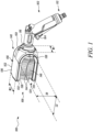
- FIG. 1 is a perspective view of a blind cleaner device 100.
- the blind cleaner device 100 may be used for different cleaning applications, such as to clean a number of lamellae (not shown) of a window blind (not shown).
- the blind cleaner device 100 includes a fluid supply device 102.
- the fluid supply device 102 includes an actuator 104 to allow passage of the fluid towards a body 106 of the blind cleaner device 100.
- the fluid supply device 102 may include any arrangement for passage of the fluid towards the body 106 of the blind cleaner device 100, such as button, knob, handle, and the like.
- the fluid supply device 102 includes a first inlet 108 (as shown in FIG. 3 ) and a first outlet 110 (as shown in FIG. 3 ).
- a hose connector 112 is removably attached to the fluid supply device 102.
- the hose connector 112 is removably attached to the first inlet 108 of the fluid supply device 102.
- the hose connector 112 includes a threaded section (not shown) to removably couple a hose pipe (not shown) with the hose connector 112.
- the hose pipe may supply the fluid from a fluid connection (not shown) towards the blind cleaner device 100.
- the fluid connection may include a tap, a pump, and the like. Further, the fluid may include water or any other cleaning fluid.
- the blind cleaner device 100 may also include a rotatable joint 116 between the body 106 and the fluid supply device 102.
- the rotatable joint 116 includes a cylindrical body, a joint inlet (not shown), and a joint outlet (not shown).
- the joint inlet is connected to the fluid supply device 102 and the joint outlet is removably coupled with an inlet portion 118 (as shown in FIG. 4 ) of the body 106.
- the joint outlet may include a threaded section (not shown) for removable coupling with the inlet portion 118 of the body 106.
- the rotatable joint 116 may allow coupling of the body 106 of the blind cleaner device 100 with the fluid supply device 102 at various angles.
- the rotatable joint 116 between the body 106 and the fluid supply device 102 provides improved ergonomics during cleaning operation. Further, the inlet portion 118 of the body 106 allows removable coupling of the body 106 with the fluid supply device 102 using the rotatable joint 116.
- the rotatable joint 116 In a vertical position (as shown in FIG. 1 to FIG. 3 ), the rotatable joint 116 allows vertical coupling of the fluid supply device 102 with the body 106 of the blind cleaner device 100. The vertical position of the fluid supply device 102 may create less disturbance for the user during the cleaning operation. In a horizontal position (not shown), the rotatable joint 116 allows horizontal coupling of the fluid supply device 102 with the body 106 of the blind cleaner device 100. In the horizontal position of the fluid supply device 102, the user may feel less weight, pressure or shocks during a cleaning operation.
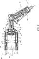
- FIG. 3 shows the blind cleaning device 100, in accordance with an embodiment of the present invention.
- the body 102 includes a distributor 127.
- the distributor 127 defines a T-shaped structure, although other shapes, types, dimensions, structure have been contemplated and are well within the scope.
- the distributor 127 includes an inlet channel 129 and two outlet channels 131.
- the outlet channels 131 are substantially perpendicular to the inlet channel 129.
- the inlet channel 129 is fluidly coupled to the inlet portion 118 of the body 106 for a fluid flow "F", such as water for cleaning, therethrough. Further, the outlet channels 131, receive the fluid flow "F” from the inlet channel 129 to supply the fluid flow "F” to each bristle plate 132, 134.
- Each bristle plate 132,134 defines an inlet opening 135 and a number of fluid nozzles 130.
- the fluid flow "F" from the outlet channels 131 of the distributor 127 enters the bristle plates 132, 134 through the inlet opening 135. Further, the fluid flow "F” is discharged through the fluid nozzles 130, such as for applications involving cleaning of the lamella of the window blind and the like.
- the present invention refers to the "fluid” or the "fluid flow” which have been used interchangeably for ease of explanation and understanding.
- the fluid flow “F” through the blind cleaner device 100 is illustrated in FIG. 3 for detail flow from the hose connector 112 to a fluid supply device 102, and then to the distributor 127 of the body 106. This fluid flow “F” then splits in the distributor 127 to move towards each bristle plate 132, 134, as illustrated in FIG. 3 .
- the blind cleaner device 100 further includes an adjustable limitation stop 120 for different lamella width.
- the limitation stop 120 may be integrated and work with the distributor 127 to allow splitting of water from the inlet channel 129 to the outlet channels 131.
- the blind cleaning device 100 may not include any limitation stop 122 and make application of the distributor 127.
- the limitation stop 120 includes a cylindrical body defining an inlet (not shown) and an outlet (not shown). The inlet is fluidly coupled to the inlet portion 118 of the body 106 to supply fluid, such as water for cleaning, therethrough. Further, the fluid is discharged through the outlet of the limitation stop 120.
- the limitation stop 120 may accommodate a jet that allows discharge of fluid therethrough.
- the limitation stop 120 can be adjusted for different lamella widths. In some examples, the limitation stop 120 can be adjusted to accommodate the lamella width that approximately lies in a range 40 Millimeters (mm) to 100 mm. This adjustment may avoid direct contact of the jet with the window blind. Furthermore, the jet may be flat or conical. The limitation stop 120 may be adjusted to obtain different types of fluid jet, such as flat fluid jet, conical fluid jet, and the like. Specifically, the limitation stop 120 can be rotated to adjust a pattern of the jet.
- the blind cleaner device 100 further includes the body 106 defining one or more openings 122.
- the opening 122 may include any size and shape.
- the body 106 includes a first body end 124, and a second body end 126.
- the body 106 also includes the inlet portion 118.
- the inlet portion 118 includes a protrusion profile 128 (as shown in FIG. 4 ).
- the protrusion profile 128 allows snap-fit connection of the fluid supply device 102 on the body 106.
- the inlet portion 118 may include a threaded profile, a press-fit profile, a snap-fit profile, or any other profile as used or known in the art, without any limitations.
- the one or more openings 122 of the blind cleaner device 100 have been interchangeably referred to as the holes of nozzles 122 (as shown in FIG. 4 ).
- the holes of nozzles 122 are disposed on the second body end 126 of the body 106.
- the blind cleaner device 100 includes two holes of nozzles 122.
- the blind cleaner device 100 may include any number, size, type, position of the holes of nozzles 122.
- the body 106 may be manufactured from any material such as a plastic, a metal, and the like, or any material as used or known in the art.
- the body 106 may be embodied as a single piece unit or the body 106 may include multiple separate parts that are joined together to form the body 106.
- the body 106 may be coupled with different types of cleaning attachments, such as, brushes, showers, nozzle, and the like.
- the body 106 is coupled with the fluid connection which provides the fluid towards the blind cleaner device 100.
- the body defines a number of fluid nozzles 130.
- the fluid nozzles 130 of the body 106 allows discharge of fluid therethrough.
- the fluid nozzles 130 and the fluid supply device 102 are fluidly connected with each other.
- the body 106 also defines a pair of bristle plates 132, 134. Specifically, the body 106 defines the first bristle plate 132 and the second bristle plate 134 facing the first bristle plate 132 and spaced apart from the first bristle plate 132.
- the pair of bristle plates 132, 134 may be similar in shape and size. Alternatively, the bristle plates 132, 134 may include different shape and size.
- the bristle plates 132, 134 define a first plate surface 136 and a second plate surface 138.
- the first plate surface 136 of the bristle plates 132, 134 include a generally planar profile.
- the first plate surface 136 includes a number of receiving slots 140.
- the second plate surface 138 of the bristle plates 132, 134 include a curved profile, although other profile, shapes such as rectangular, square have been contemplated and are well within the scope of the present invention.
- the pair of bristle plates 132, 134 are connected with each other by a connecting portion 142.
- the pair of bristle plates 132, 134 and the connecting portion 142 are embodied as an integral unit.
- the pair of bristle plates 132, 134 and the connecting portion 142 may be embodied as separate parts that are joined together.
- the pair of bristle plates 132, 134 and the connecting portion 142 form a generally U-shaped structure.
- the pair of bristle plates 132, 134 are substantially parallel.
- the fluid nozzles 130 are evenly disposed on the second plate surface 138 of the pair of bristle plates 132, 134, such that the fluid nozzles 130 of first bristle plate 132 face the fluid nozzles 130 of the second bristle plate 134. As shown in FIG. 3 , the fluid nozzles 130 are fluidly connected to the fluid supply device 102. The fluid may be sprayed on to the lamella of the window blind through upper side and lower side.
- the body 106 further defines a pair of bristle brushes 144 coupled with the pair of the bristle plates 132, 134.
- the pair of bristle brushes 144 are disposed on the second plate surface 138, adjacent to the fluid nozzles 130, and extend therefrom.
- Each of the pair of bristle brushes 144 includes a plurality of bristles 146 (best shown in FIG. 1 ).
- the pair of bristles 146 of the pair of bristle brushes 144 overlap each other.
- the bristles 146 are tilted and arranged in a shape that is similar to the shape of the lamellae of the window blind. This arrangement allows uniform cleaning of the lamella surface.
- the bristles 146 may include a first row of bristles (not shown) that are disposed on an outer side of the brushes and a second row of bristles (not shown) that are disposed on an inner side of the bristle brushes 144.
- the first row of bristles may include soft bristles, and the second row of bristles may include hard bristles. The first row of bristles and the second row of bristles are in contact with each other.
- each bristle plate 132, 134 includes a bristle fixation element 147 (as shown in FIG. 3 ) to removably couple the pair of bristle brushes 144.
- the bristle fixation element 147 can be removably coupled to the bristle plates 132, 134.
- the bristle fixation element 147 may be made up of a soft plastic material.
- the bristle fixation element 147 allows removable coupling of the pair of bristle brushes 144 with the bristle plates 132, 134.
- the removable coupling of the pair of bristle brushes 144 allows coupling of different types of bristle brushes.
- the bristles 146 of each bristle 144 brush may be manufactured using a synthetic material, such as nylon. It should be noted that the bristles 146 may include any other material, without limiting the scope of the present invention.
- the blind cleaner device 100 further includes a cover 148 attached with the body 106 of the blind cleaner device 100.
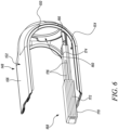
- FIG. 5 illustrates the cover 148 in a disassembled state with the body 106 of the blind cleaner device 100, for explanation and clarity considerations.
- the cover 148 of the present invention may be readily and efficiently assembled or disassembled with the body 106 of the blind cleaner device 100, for different applications and/or service requirements.
- the cover 148 may be manufactured from a plastic, a metal, and the like.
- the cover 148 may be embodied as a single piece unit or the cover 148 may include multiple separate parts that are joined together to form the cover 148.
- the cover 148 includes a first portion 150 and two second portions 152
- the first portion 150 defines a first portion height "H1", and a first portion width "W1".
- the second portions 152 defines a second portion length "L2", and a second portion width "W2".
- the cover 148 also includes a first cover surface 154, and a second cover surface 156.
- the first cover surface 154 defines a number of projections (not shown here, but maybe similar to projections 258) to engage with the receiving slots 140 of the bristle plates 132, 134.
- the pair of bristle plates 132, 134 may be coupled to the cover 148 using a snap-fit connection. It should be noted that the pair of bristle plates 132, 134 and the cover 148 may be connected by any other means such as glue, welding, screws, bolts, rivets and the like, without limiting the scope of the present invention.
- the cover 148 includes a generally U-shaped structure herein.
- the U-shaped structure of the cover 148 receives the body 106 of the blind cleaner device 100. It should be noted that the cover 148 may include any other shape and size, without limiting the scope of the present invention.
- the cover 148 includes four projections. In other examples, the cover 148 may include any number, type, size, position of the projections without limiting the scope of the present invention.
- the cover 148 further includes a circular hole 160 to receive the inlet portion 118 of the body 106.
- the cover 148 includes one or more sealing plugs 162.
- the sealing plug 162 includes a conical shape.
- the holes of nozzles 122 receive the sealing plugs 162, such that the sealing plugs 162 restrict the discharge of fluid therethrough.
- the profile and cross section of the sealing plugs 162 are same or similar (say including some tolerances, fitment scope and the like) as that of the holes of nozzles 122 to properly seal the holes of nozzles 122.
- the one or more sealing plugs 162 close one or more holes of nozzles 122 of the blind cleaner device 100.
- the first portion 150 includes the sealing plugs 162.
- the sealing plugs 162 are disposed on the first portion 150 of the cover 148, such that the sealing plugs 162 align with the holes of nozzles 122 (see FIG. 5 ).
- the blind cleaner device 100 includes two holes of nozzles 122, and the cover 148 includes two sealing plugs 162, respectively.
- the blind cleaner device 100, and the cover 148 may include any number, type, position, size, arrangement of the holes of nozzles 122, and the sealing plugs 162, respectively, without limiting the scope of the present invention.
- Each of the one or more sealing plugs 162 further includes an O-ring seal 166 to plug the corresponding opening 122 of the one or more openings 122.
- the O-ring seal 166 incudes a circular shape.
- the O-ring seal 166 also includes an inner diameter which is about same or similar in dimensions as that of a diameter of the sealing plug, and an outer diameter that is about same or similar in dimensions as that of a diameter of the corresponding opening 122.
- the O-ring seal 166 may be manufactured using any material, such as a rubber, a graphite, a metal, a plastic, and the like.
- the O-ring seal 166 is disposed between the holes of nozzles 122 and the sealing plugs 162, such that it restricts the leakage of fluid therethrough.
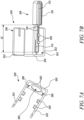
- the blind cleaner device 100 includes a seal mounting tool 168 to mount the O-ring seal 166 to the one or more sealing plugs 162.
- the seal mounting tool 168 is a portable tool which includes a simple construction.
- the seal mounting tool 168 includes a handle 170.
- the handle 170 includes a rectangular shape. It should be noted that the handle 170 may include any shape and size without limiting the scope of the present invention.
- the handle 170 also includes a gripping part 172 for proper grip of a user during the mounting of the O-ring seal 166 to the sealing plug 162.
- the gripping part 172 may include a knurled surface.
- the seal mounting tool 168 also includes a mounting part 174 defined with the handle 170.
- the mounting part 174 allows mounting of the O-ring seal 166 with the one or more sealing plugs 162 of the cover 148.
- the mounting part 174 of the seal mounting tool 168 includes a number of grooves 176.
- a cover 248 is illustrated.
- the cover 248 includes a first portion 250 and two second portions 252 substantially perpendicular to the first portion 250.
- the cover 248 generally includes a rectangular shape and thereby may find applications with the blind cleaner device 100 having a substantially rectangular body 106.
- the cover 248 defines a first cover surface 254 and a second cover surface 256.
- the first cover surface 254 defines the number of projections 258.
- the projections 258 may allow desired engagement of the seal mounting tool 168 with the cover 248, as illustrated.
- the cover 248 include a circular hole 260.
- the cover 248 also includes one or more sealing plugs 262. Each sealing plug 262 includes an O-ring seal 266.
- the cover 248 is similar to cover 148 in construction and working. Further, the cover 248 allows application of the seal mounting tool 168, as illustrated herein, for mounting of the O-ring seal 266 with each of the sealing plug 262.
- the mounting part 174 of the seal mounting tool 168 includes a longitudinal body. Further, the longitudinal body of the mounting part 174 defines a mounting length "L3" (shown in FIG. 7B ) which is preferably greater than the second portions 252 length "L2" of the cover 248.
- the present invention provides the improved blind cleaner device 100 to provide desired cleaning operations such as to clean the lamellae of window blinds effectively and efficiently.
- the blind cleaner device 100 allows cleaning of the window blinds with or without fluid.
- the blind cleaner device 100 includes fewer parts and can be easily assembled without requiring additional tools. Further, the blind cleaner device 100 is easy and convenient to use for users and does not cause user fatigue.
- the present invention provides the cover 148 having the sealing plugs 162 to close the holes of nozzles 122 on the body 106 to prevent discharge of cleaning fluid therethrough.
- the sealing plugs 162 are integrated with the cover 148, 248 which reduce the quantity of parts in the blind cleaner device 100.
- the present invention provides that the users may not forget or misplace the sealing plugs 162 as the sealing plugs 162 are integrated part of the cover 148, 248.
- the O-ring seal 166 properly seals the corresponding opening 122 to avoid leakage of cleaning fluid therethrough.
- the seal mounting tool 168 allows easy and quick mounting of the O-ring seal 166 on the sealing plugs 162.
Landscapes
- Nozzles For Electric Vacuum Cleaners (AREA)
- Cleaning By Liquid Or Steam (AREA)
- Cleaning In General (AREA)
Claims (6)
- Jalousiereinigungsvorrichtung (100), umfassend:einen Körper (106), der eine oder mehrere Öffnungen (122) definiert; undeine Abdeckung (148, 248), die zur Befestigung am Körper (106) der Jalousiereinigungsvorrichtung (100) ausgelegt ist;dadurch gekennzeichnet, dass:
die Abdeckung (148, 248) einen oder mehrere Abdichtungsstopfen (162) einschließt, wobei jeder des einen oder der mehreren Abdichtungsstopfen (162) der Abdeckung (148, 248) dazu ausgelegt ist, eine entsprechende Öffnung (122) der einen oder mehreren Öffnungen (122) des Körpers (106) wasserdicht zu verstopfen. - Jalousiereinigungsvorrichtung (100) nach Anspruch 1, wobei jeder des einen oder der mehreren Abdichtungsstopfen (162) ferner eine O-Ring-Dichtung (166) einschließt, um die entsprechende Öffnung (122) der einen oder mehreren Öffnungen (122) zu verstopfen.
- Jalousiereinigungsvorrichtung (100) nach Anspruch 1, wobei der eine oder die mehreren Abdichtungsstopfen (162) dazu ausgelegt sind, die eine oder die mehreren Öffnungen (122) der Jalousiereinigungsvorrichtung (100) zu verschließen.
- Jalousiereinigungsvorrichtung (100) nach Anspruch 1, wobei die Abdeckung (148, 248) einen ersten Abschnitt (150) und zwei zweite Abschnitte (152) im Wesentlichen senkrecht zum ersten Abschnitt (150) einschließt.
- Jalousiereinigungsvorrichtung (100) nach Anspruch 4, wobei der erste Abschnitt (150) die Abdichtungsstopfen (162) einschließt.
- Jalousiereinigungsvorrichtung (100) nach einem der vorstehenden Ansprüche, wobei die Abdeckung (148, 248) eine erste Abdeckoberfläche (154) und eine zweite Abdeckoberfläche (156) einschließt, wobei die erste Abdeckoberfläche (154) eine Anzahl von Vorsprüngen (258) definiert, die einen gewünschten Eingriff eines Dichtungsmontagewerkzeugs (168) mit der Abdeckung (148, 248 ) ermöglichen.
Applications Claiming Priority (2)
| Application Number | Priority Date | Filing Date | Title |
|---|---|---|---|
| EP21186664 | 2021-07-20 | ||
| PCT/EP2022/064632 WO2023001435A1 (en) | 2021-07-20 | 2022-05-30 | Blind cleaner device |
Publications (2)
| Publication Number | Publication Date |
|---|---|
| EP4373372A1 EP4373372A1 (de) | 2024-05-29 |
| EP4373372B1 true EP4373372B1 (de) | 2025-01-29 |
Family
ID=76999704
Family Applications (1)
| Application Number | Title | Priority Date | Filing Date |
|---|---|---|---|
| EP22730899.6A Active EP4373372B1 (de) | 2021-07-20 | 2022-05-30 | Jalousienreinigungsgerät |
Country Status (4)
| Country | Link |
|---|---|
| EP (1) | EP4373372B1 (de) |
| CN (1) | CN117677328B (de) |
| TW (1) | TW202332403A (de) |
| WO (1) | WO2023001435A1 (de) |
Family Cites Families (11)
| Publication number | Priority date | Publication date | Assignee | Title |
|---|---|---|---|---|
| CA513865A (en) * | 1955-06-21 | Meyer Gottfried | Apparatus for washing venetian blinds | |
| US2487444A (en) * | 1945-10-25 | 1949-11-08 | Julian M Ines | Suction brush for venetian blinds |
| US2788537A (en) * | 1953-12-18 | 1957-04-16 | Greenberg Seymour | Fluid holding venetian blind cleaner |
| US3892004A (en) * | 1972-10-06 | 1975-07-01 | Thomas Downes | Domestic cleaning apparatus |
| US4118822A (en) * | 1977-06-23 | 1978-10-10 | Gitter John E | Louvered window cleaner |
| AU656326B2 (en) * | 1990-08-10 | 1995-02-02 | Andy DE PETRA | Slat cleaning apparatus |
| US7194783B1 (en) * | 2004-02-20 | 2007-03-27 | Gene C. Hunt | Window blind cleaning apparatus |
| CN101283888B (zh) * | 2008-06-02 | 2010-09-15 | 中国农业大学 | 便携式纱窗清洁器 |
| DE102008034005A1 (de) * | 2008-07-21 | 2010-01-28 | Jäger, Anton | Reinigungsvorrichtung |
| ES1073038Y (es) * | 2010-09-20 | 2011-01-31 | Villa Luis Alberto Torres | Dispositivo de limpieza para persianas |
| CN203302983U (zh) * | 2013-05-31 | 2013-11-27 | 重庆交通大学 | 百叶窗清洁刷 |
-
2022
- 2022-05-30 CN CN202280051419.2A patent/CN117677328B/zh active Active
- 2022-05-30 EP EP22730899.6A patent/EP4373372B1/de active Active
- 2022-05-30 WO PCT/EP2022/064632 patent/WO2023001435A1/en not_active Ceased
- 2022-07-13 TW TW111126196A patent/TW202332403A/zh unknown
Also Published As
| Publication number | Publication date |
|---|---|
| EP4373372A1 (de) | 2024-05-29 |
| WO2023001435A1 (en) | 2023-01-26 |
| CN117677328A (zh) | 2024-03-08 |
| CN117677328B (zh) | 2024-08-13 |
| TW202332403A (zh) | 2023-08-16 |
Similar Documents
| Publication | Publication Date | Title |
|---|---|---|
| EP3989790B1 (de) | Vakuumwerkzeuge | |
| AU2017225979B2 (en) | Systems and methods for providing a wand for a floor cleaning appartatus | |
| US6474896B1 (en) | Oscillating aqua broom | |
| US20090094791A1 (en) | Combination handle and extension handle kit for cleaning implements | |
| US5535478A (en) | Cleaning tool for removing lint from clothes dryers | |
| WO2007133649A2 (en) | Ergonomic window cleaning apparatus | |
| US4334336A (en) | Surface cleaning vacuum nozzle | |
| CN107205609A (zh) | 包括通用手柄和可互换的工具头部的工具组合件 | |
| KR101720246B1 (ko) | 청소도구용 탈착식 물분사장치 | |
| US7287926B2 (en) | Fluid squeegee | |
| WO2015109498A1 (zh) | 转接管构件以及吸尘器吸嘴 | |
| US7194783B1 (en) | Window blind cleaning apparatus | |
| US20110047745A1 (en) | Vacuum accessory tool | |
| EP4477126A1 (de) | Rotierendes scheuerwerkzeug für reinigungsvorrichtung | |
| WO2023001435A1 (en) | Blind cleaner device | |
| EP4122364B1 (de) | Vorrichtung zur reinigung von jalousien | |
| EP3283232B1 (de) | Teleskopisches rohr | |
| US5819365A (en) | Window washing accessory cleaning tool for use with water extraction cleaning machine | |
| CN210700690U (zh) | 自清洁花洒 | |
| RU2647234C2 (ru) | Насадочное всасывающее устройство для чистящего аппарата и чистящий аппарат | |
| US20190343352A1 (en) | Air nozzles with bristles and scrapers | |
| KR20260007349A (ko) | 브러시 헤드 및 표면 청소 디바이스 | |
| JP4822135B2 (ja) | 蒸気洗浄具 | |
| US20070151069A1 (en) | Apparatus for rapid and thorough edge cleaning of hard surfaces | |
| KR101663242B1 (ko) | 도장부스 내부의 이물질 제거용 스크레퍼 |
Legal Events
| Date | Code | Title | Description |
|---|---|---|---|
| STAA | Information on the status of an ep patent application or granted ep patent |
Free format text: STATUS: UNKNOWN |
|
| STAA | Information on the status of an ep patent application or granted ep patent |
Free format text: STATUS: THE INTERNATIONAL PUBLICATION HAS BEEN MADE |
|
| PUAI | Public reference made under article 153(3) epc to a published international application that has entered the european phase |
Free format text: ORIGINAL CODE: 0009012 |
|
| STAA | Information on the status of an ep patent application or granted ep patent |
Free format text: STATUS: REQUEST FOR EXAMINATION WAS MADE |
|
| 17P | Request for examination filed |
Effective date: 20231215 |
|
| AK | Designated contracting states |
Kind code of ref document: A1 Designated state(s): AL AT BE BG CH CY CZ DE DK EE ES FI FR GB GR HR HU IE IS IT LI LT LU LV MC MK MT NL NO PL PT RO RS SE SI SK SM TR |
|
| GRAP | Despatch of communication of intention to grant a patent |
Free format text: ORIGINAL CODE: EPIDOSNIGR1 |
|
| STAA | Information on the status of an ep patent application or granted ep patent |
Free format text: STATUS: GRANT OF PATENT IS INTENDED |
|
| DAV | Request for validation of the european patent (deleted) | ||
| DAX | Request for extension of the european patent (deleted) | ||
| INTG | Intention to grant announced |
Effective date: 20241029 |
|
| GRAS | Grant fee paid |
Free format text: ORIGINAL CODE: EPIDOSNIGR3 |
|
| GRAA | (expected) grant |
Free format text: ORIGINAL CODE: 0009210 |
|
| STAA | Information on the status of an ep patent application or granted ep patent |
Free format text: STATUS: THE PATENT HAS BEEN GRANTED |
|
| P01 | Opt-out of the competence of the unified patent court (upc) registered |
Free format text: CASE NUMBER: APP_66825/2024 Effective date: 20241217 |
|
| AK | Designated contracting states |
Kind code of ref document: B1 Designated state(s): AL AT BE BG CH CY CZ DE DK EE ES FI FR GB GR HR HU IE IS IT LI LT LU LV MC MK MT NL NO PL PT RO RS SE SI SK SM TR |
|
| REG | Reference to a national code |
Ref country code: GB Ref legal event code: FG4D |
|
| REG | Reference to a national code |
Ref country code: CH Ref legal event code: EP |
|
| REG | Reference to a national code |
Ref country code: DE Ref legal event code: R096 Ref document number: 602022010231 Country of ref document: DE |
|
| REG | Reference to a national code |
Ref country code: IE Ref legal event code: FG4D |
|
| REG | Reference to a national code |
Ref country code: NL Ref legal event code: MP Effective date: 20250129 |
|
| PG25 | Lapsed in a contracting state [announced via postgrant information from national office to epo] |
Ref country code: NL Free format text: LAPSE BECAUSE OF FAILURE TO SUBMIT A TRANSLATION OF THE DESCRIPTION OR TO PAY THE FEE WITHIN THE PRESCRIBED TIME-LIMIT Effective date: 20250129 |
|
| PG25 | Lapsed in a contracting state [announced via postgrant information from national office to epo] |
Ref country code: RS Free format text: LAPSE BECAUSE OF FAILURE TO SUBMIT A TRANSLATION OF THE DESCRIPTION OR TO PAY THE FEE WITHIN THE PRESCRIBED TIME-LIMIT Effective date: 20250429 |
|
| PG25 | Lapsed in a contracting state [announced via postgrant information from national office to epo] |
Ref country code: FI Free format text: LAPSE BECAUSE OF FAILURE TO SUBMIT A TRANSLATION OF THE DESCRIPTION OR TO PAY THE FEE WITHIN THE PRESCRIBED TIME-LIMIT Effective date: 20250129 |
|
| PG25 | Lapsed in a contracting state [announced via postgrant information from national office to epo] |
Ref country code: PL Free format text: LAPSE BECAUSE OF FAILURE TO SUBMIT A TRANSLATION OF THE DESCRIPTION OR TO PAY THE FEE WITHIN THE PRESCRIBED TIME-LIMIT Effective date: 20250129 |
|
| PGFP | Annual fee paid to national office [announced via postgrant information from national office to epo] |
Ref country code: DE Payment date: 20250409 Year of fee payment: 4 |
|
| PG25 | Lapsed in a contracting state [announced via postgrant information from national office to epo] |
Ref country code: ES Free format text: LAPSE BECAUSE OF FAILURE TO SUBMIT A TRANSLATION OF THE DESCRIPTION OR TO PAY THE FEE WITHIN THE PRESCRIBED TIME-LIMIT Effective date: 20250129 |
|
| REG | Reference to a national code |
Ref country code: LT Ref legal event code: MG9D |
|
| PG25 | Lapsed in a contracting state [announced via postgrant information from national office to epo] |
Ref country code: IS Free format text: LAPSE BECAUSE OF FAILURE TO SUBMIT A TRANSLATION OF THE DESCRIPTION OR TO PAY THE FEE WITHIN THE PRESCRIBED TIME-LIMIT Effective date: 20250529 Ref country code: NO Free format text: LAPSE BECAUSE OF FAILURE TO SUBMIT A TRANSLATION OF THE DESCRIPTION OR TO PAY THE FEE WITHIN THE PRESCRIBED TIME-LIMIT Effective date: 20250429 |
|
| REG | Reference to a national code |
Ref country code: AT Ref legal event code: MK05 Ref document number: 1762579 Country of ref document: AT Kind code of ref document: T Effective date: 20250129 |
|
| PG25 | Lapsed in a contracting state [announced via postgrant information from national office to epo] |
Ref country code: HR Free format text: LAPSE BECAUSE OF FAILURE TO SUBMIT A TRANSLATION OF THE DESCRIPTION OR TO PAY THE FEE WITHIN THE PRESCRIBED TIME-LIMIT Effective date: 20250129 |
|
| PG25 | Lapsed in a contracting state [announced via postgrant information from national office to epo] |
Ref country code: LV Free format text: LAPSE BECAUSE OF FAILURE TO SUBMIT A TRANSLATION OF THE DESCRIPTION OR TO PAY THE FEE WITHIN THE PRESCRIBED TIME-LIMIT Effective date: 20250129 Ref country code: PT Free format text: LAPSE BECAUSE OF FAILURE TO SUBMIT A TRANSLATION OF THE DESCRIPTION OR TO PAY THE FEE WITHIN THE PRESCRIBED TIME-LIMIT Effective date: 20250529 |
|
| PG25 | Lapsed in a contracting state [announced via postgrant information from national office to epo] |
Ref country code: BG Free format text: LAPSE BECAUSE OF FAILURE TO SUBMIT A TRANSLATION OF THE DESCRIPTION OR TO PAY THE FEE WITHIN THE PRESCRIBED TIME-LIMIT Effective date: 20250129 Ref country code: GR Free format text: LAPSE BECAUSE OF FAILURE TO SUBMIT A TRANSLATION OF THE DESCRIPTION OR TO PAY THE FEE WITHIN THE PRESCRIBED TIME-LIMIT Effective date: 20250430 |
|
| PG25 | Lapsed in a contracting state [announced via postgrant information from national office to epo] |
Ref country code: AT Free format text: LAPSE BECAUSE OF FAILURE TO SUBMIT A TRANSLATION OF THE DESCRIPTION OR TO PAY THE FEE WITHIN THE PRESCRIBED TIME-LIMIT Effective date: 20250129 |
|
| PG25 | Lapsed in a contracting state [announced via postgrant information from national office to epo] |
Ref country code: SE Free format text: LAPSE BECAUSE OF FAILURE TO SUBMIT A TRANSLATION OF THE DESCRIPTION OR TO PAY THE FEE WITHIN THE PRESCRIBED TIME-LIMIT Effective date: 20250129 |
|
| PG25 | Lapsed in a contracting state [announced via postgrant information from national office to epo] |
Ref country code: SM Free format text: LAPSE BECAUSE OF FAILURE TO SUBMIT A TRANSLATION OF THE DESCRIPTION OR TO PAY THE FEE WITHIN THE PRESCRIBED TIME-LIMIT Effective date: 20250129 |
|
| PG25 | Lapsed in a contracting state [announced via postgrant information from national office to epo] |
Ref country code: DK Free format text: LAPSE BECAUSE OF FAILURE TO SUBMIT A TRANSLATION OF THE DESCRIPTION OR TO PAY THE FEE WITHIN THE PRESCRIBED TIME-LIMIT Effective date: 20250129 |
|
| PG25 | Lapsed in a contracting state [announced via postgrant information from national office to epo] |
Ref country code: IT Free format text: LAPSE BECAUSE OF FAILURE TO SUBMIT A TRANSLATION OF THE DESCRIPTION OR TO PAY THE FEE WITHIN THE PRESCRIBED TIME-LIMIT Effective date: 20250129 |
|
| PG25 | Lapsed in a contracting state [announced via postgrant information from national office to epo] |
Ref country code: EE Free format text: LAPSE BECAUSE OF FAILURE TO SUBMIT A TRANSLATION OF THE DESCRIPTION OR TO PAY THE FEE WITHIN THE PRESCRIBED TIME-LIMIT Effective date: 20250129 Ref country code: CZ Free format text: LAPSE BECAUSE OF FAILURE TO SUBMIT A TRANSLATION OF THE DESCRIPTION OR TO PAY THE FEE WITHIN THE PRESCRIBED TIME-LIMIT Effective date: 20250129 |
|
| PG25 | Lapsed in a contracting state [announced via postgrant information from national office to epo] |
Ref country code: RO Free format text: LAPSE BECAUSE OF FAILURE TO SUBMIT A TRANSLATION OF THE DESCRIPTION OR TO PAY THE FEE WITHIN THE PRESCRIBED TIME-LIMIT Effective date: 20250129 |
|
| PG25 | Lapsed in a contracting state [announced via postgrant information from national office to epo] |
Ref country code: SK Free format text: LAPSE BECAUSE OF FAILURE TO SUBMIT A TRANSLATION OF THE DESCRIPTION OR TO PAY THE FEE WITHIN THE PRESCRIBED TIME-LIMIT Effective date: 20250129 |
|
| REG | Reference to a national code |
Ref country code: DE Ref legal event code: R097 Ref document number: 602022010231 Country of ref document: DE |
|
| PLBE | No opposition filed within time limit |
Free format text: ORIGINAL CODE: 0009261 |
|
| STAA | Information on the status of an ep patent application or granted ep patent |
Free format text: STATUS: NO OPPOSITION FILED WITHIN TIME LIMIT |
|
| REG | Reference to a national code |
Ref country code: CH Ref legal event code: L10 Free format text: ST27 STATUS EVENT CODE: U-0-0-L10-L00 (AS PROVIDED BY THE NATIONAL OFFICE) Effective date: 20251210 |
|
| REG | Reference to a national code |
Ref country code: CH Ref legal event code: H13 Free format text: ST27 STATUS EVENT CODE: U-0-0-H10-H13 (AS PROVIDED BY THE NATIONAL OFFICE) Effective date: 20251223 |
|
| 26N | No opposition filed |
Effective date: 20251030 |
|
| PG25 | Lapsed in a contracting state [announced via postgrant information from national office to epo] |
Ref country code: LU Free format text: LAPSE BECAUSE OF NON-PAYMENT OF DUE FEES Effective date: 20250530 |
|
| PG25 | Lapsed in a contracting state [announced via postgrant information from national office to epo] |
Ref country code: CH Free format text: LAPSE BECAUSE OF NON-PAYMENT OF DUE FEES Effective date: 20250531 |
|
| REG | Reference to a national code |
Ref country code: BE Ref legal event code: MM Effective date: 20250531 |
|
| PG25 | Lapsed in a contracting state [announced via postgrant information from national office to epo] |
Ref country code: MC Free format text: LAPSE BECAUSE OF FAILURE TO SUBMIT A TRANSLATION OF THE DESCRIPTION OR TO PAY THE FEE WITHIN THE PRESCRIBED TIME-LIMIT Effective date: 20250129 |
|
| PG25 | Lapsed in a contracting state [announced via postgrant information from national office to epo] |
Ref country code: IE Free format text: LAPSE BECAUSE OF NON-PAYMENT OF DUE FEES Effective date: 20250530 |
|
| PG25 | Lapsed in a contracting state [announced via postgrant information from national office to epo] |
Ref country code: BE Free format text: LAPSE BECAUSE OF NON-PAYMENT OF DUE FEES Effective date: 20250531 |
|
| PG25 | Lapsed in a contracting state [announced via postgrant information from national office to epo] |
Ref country code: FR Free format text: LAPSE BECAUSE OF NON-PAYMENT OF DUE FEES Effective date: 20250531 |