EP4122310B1 - Rasenmäher und zugehörige befestigung - Google Patents
Rasenmäher und zugehörige befestigung Download PDFInfo
- Publication number
- EP4122310B1 EP4122310B1 EP22185403.7A EP22185403A EP4122310B1 EP 4122310 B1 EP4122310 B1 EP 4122310B1 EP 22185403 A EP22185403 A EP 22185403A EP 4122310 B1 EP4122310 B1 EP 4122310B1
- Authority
- EP
- European Patent Office
- Prior art keywords
- attachment
- lawn mower
- cover
- opening
- open
- Prior art date
- Legal status (The legal status is an assumption and is not a legal conclusion. Google has not performed a legal analysis and makes no representation as to the accuracy of the status listed.)
- Active
Links
Images


Classifications
-
- A—HUMAN NECESSITIES
- A01—AGRICULTURE; FORESTRY; ANIMAL HUSBANDRY; HUNTING; TRAPPING; FISHING
- A01D—HARVESTING; MOWING
- A01D43/00—Mowers combined with apparatus performing additional operations while mowing
- A01D43/06—Mowers combined with apparatus performing additional operations while mowing with means for collecting, gathering or loading mown material
- A01D43/063—Mowers combined with apparatus performing additional operations while mowing with means for collecting, gathering or loading mown material in or into a container carried by the mower; Containers therefor
- A01D43/0635—Mowers combined with apparatus performing additional operations while mowing with means for collecting, gathering or loading mown material in or into a container carried by the mower; Containers therefor with emptying means
-
- A—HUMAN NECESSITIES
- A01—AGRICULTURE; FORESTRY; ANIMAL HUSBANDRY; HUNTING; TRAPPING; FISHING
- A01D—HARVESTING; MOWING
- A01D43/00—Mowers combined with apparatus performing additional operations while mowing
- A01D43/06—Mowers combined with apparatus performing additional operations while mowing with means for collecting, gathering or loading mown material
- A01D43/063—Mowers combined with apparatus performing additional operations while mowing with means for collecting, gathering or loading mown material in or into a container carried by the mower; Containers therefor
- A01D43/0638—Rigid containers
-
- A—HUMAN NECESSITIES
- A01—AGRICULTURE; FORESTRY; ANIMAL HUSBANDRY; HUNTING; TRAPPING; FISHING
- A01D—HARVESTING; MOWING
- A01D2101/00—Lawn-mowers
Definitions
- the present disclosure relates generally to lawn mowers, and more particularly to attachments for lawn mowers.
- Lawn mowers are generally utilized in grass cutting operations. However, they may also be used in other operations, such as picking up of leaves and other debris.
- lawn mowers When in use, lawn mowers generally discharge debris from a mower deck. Many operators discharge this debris from the mower deck after the debris has been cut down into finer-sized particles. Other operators prefer to collect the debris and remove it from their yards. Removing debris requires operators to move and empty loaded containers which are heavy.
- an attachment for a push lawn mower includes a body including one or more sidewalls defining an internal volume configured to receive clippings from the lawn mower, wherein the body defines an opening; and a cover coupled to the body at the opening and movable between an open position, whereby the opening is open, and a closed position, whereby the opening is closed, wherein the cover is selectively lockable in the open position, and wherein the cover is biased to the closed position by a spring.
- a lawn mower in accordance with another embodiment, includes a mower deck defining a cutting area; a cutting implement disposed in the cutting area; a debris egress location in communication with the cutting area; and an attachment comprising: a body including one or more sidewalls defining an internal volume configured to receive clippings from the lawn mower, wherein the body defines an opening configured to be disposed at the debris egress location; and a cover coupled to the body at the opening and movable between an open position, whereby the opening is open, and a closed position, whereby the opening is closed, wherein the cover comprises an opening configured to be in open communication with the debris egress location of the lawn mower.
- a method of using an attachment with a lawn mower includes removing the attachment from the lawn mower, the attachment having a cover disposed at, and configured to selectively close, an opening of a body of the attachment, wherein the cover is in a closed position whereby the opening is closed; reconfiguring the cover to an open position by pivoting the cover from the closed position; removing material from an internal volume of the attachment through the opening; reconfiguring the cover to the closed position; and attaching the attachment to the lawn mower such that the cover is in communication with a debris egress location of the lawn mower.
- a process, method, article, or apparatus that comprises a list of features is not necessarily limited only to those features but may include other features not expressly listed or inherent to such process, method, article, or apparatus.
- "or" refers to an inclusive- or and not to an exclusive- or. For example, a condition A or B is satisfied by any one of the following: A is true (or present) and B is false (or not present), A is false (or not present) and B is true (or present), and both A and B are true (or present).
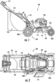
- the mower deck 102 can include another debris egress location located at a different position than the debris egress location 114.
- the other debris egress location can be disposed at a rear end of the mower deck 102. More particularly, the other debris egress location can extend through the sidewall of the mower deck 102 at the rear of the mower deck 102. Unless states otherwise, reference made hereinafter to the debris egress location is intended to refer to the debris egress location disposed at the rear of the mower deck 102.
- the lawn mower 100 can further include an attachment 120 configured to be removably attached to the lawn mower 100, e.g., at or adjacent to the mower deck 102 or the handle 110.
- the attachment 120 can define a first size 122, as measured from a top view, that is less than a second size 124, as measured from the top view, of the handle 110.
- the first and second sizes may refer to areal dimensions of the footprints of the attachment 120 and handle 110, respectively.
- the footprints may be mapped when the handle 110 and attachment 120 are both in the in-use configurations.
- the attachment 120 may be at least one of narrower or shorter than the handle 110. In this regard, the attachment 120 may not form an outer surface of the lawn mower 100 which might impact objects as the lawn mower 100 passes thereby.
- the attachment 120 includes an opening 140 in the sidewall 128.
- the opening 140 is in fluid communication with the internal volume 138.
- the opening 140 may be located at a front end of the attachment 120.
- the opening 140 may extend entirely between the top, left, right, and bottom sidewalls 130, 132, 134, and 136.
- the opening 140 may include a plurality of openings disposed between the top, left, right, and bottom sidewalls 130, 132, 134, and 136.
- the left and right sidewalls 132 and 136 each include a sloped edge located between the forward and top sides of the attachment 120.
- the opening 140 can include a corresponding sloped edge and conform generally to the shape of the edges of the top, left, right, and bottom sidewalls 130, 132, 134, and 136.
- the body 126 can have a generally rigid construction. That is, for example, the body 126 can be formed from a material having a relatively stiff sidewall. Exemplary materials include one or more of metals, alloys, polymers, or the like.
- the body 126 can be configured to receive an internal element within the internal volume 138.
- the internal element can include, for example, a relatively non-rigid sidewall. Reference made to relative rigidity of the body 126 and the internal element is made with respect to the other of the body 126 and the internal element. That is, for example, the body 126 can be more rigid than the internal element.
- the internal element can include a fabric material having a relatively non-rigid sidewall.
- the internal element may be configured to conform, or generally conform, to the shape of the internal volume 138 of the body 126.
- the internal element may be attachable to the body 126 to, e.g., align the internal element and prevent movement with respect to the body 126.
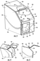
- a cover 142 can be coupled to the body 126.
- the cover 142 can include two or more segments, such as a first segment 144 and a second segment 146.
- the first and second segments 144 and 146 may define generally planar shapes that intersect one another.
- the cover 142 may accommodate embodiments of the lawn mower 100 where the left and right sidewalls 132 and 136 have sloped edges.
- the cover 142 may automatically return to the closed position.
- the cover 142 may be biased to the closed position.
- the cover 142 may be rotatably biased by a biasing element.
- the biasing element may include a spring, such as a torsion spring. The biasing element can rotationally bias the cover 142 to pivot towards the closed position.
- the cover 142 may further include an opening 150.
- the opening 150 may extend through the cover 142.
- the opening 150 can define an areal size less than an areal size of the cover 142.
- a ratio of the areal size of the opening 150 to the areal size of the cover 142 [A OPENING :A COVER ] is in a range of 1:100 and 1:1.25, such as in a range of 1:2 and 1:25, such as in a range of 1:3 and 1:10, such as in a range of 1:4 and 1:8.
- the areal size of the opening 150 is within +/- 50% of an areal size of an opening of the debris egress location of the cutting area 104, such as within +/- 25% of the areal size of the opening of the debris egress location, such as within +/- 10% of the areal size of the opening of the debris egress location.
- the areal size of the opening 150 can be equal to the areal size of the opening of the debris egress location of the cutting area 104.
- the opening 150 is laterally offset from a centerline of the attachment 120.
- the opening 150 can be laterally offset from the centerline by a same distance of offset as the debris egress location.
- the opening 150 can receive the debris discharged from the debris egress location.
- the opening 150 is disposed in the second segment 146 of the cover 142.
- the opening 150 can be disposed in another segment of the cover 142, or extend over a plurality of the segments, as long as the opening 150 is in open communication with the debris egress location of the cutting area 104 when the attachment 120 is attached to the lawn mower 100.
- the cover 142 includes a handle 152.
- the handle 152 can extend from the first segment 144. In the embodiment in FIG. 5 , the handle 152 extends from the first segment 144 at an approximately 90 degree angle. In another embodiment, the handle 152 can be canted, i.e., angularly offset, from the first segment 144. In another embodiment, the handle 152 can be coupled to a different portion of the cover 142, such as the second segment 146.
- the operator may grab the cover 142 so as to reconfigure the cover 142 by grabbing the handle 152.
- the cover 142 may be lockable in the closed position.
- the attachment 120 may be lifted by the handle 152 without debris emptying through the opening 140.
- the operator may utilize the handle 152 at least for reconfiguring the cover 142 so as to allow emptying of the debris and clippings from the internal volume 138 of the attachment 120.
- a secondary handle 154 may be coupled to the attachment 120.
- the secondary handle 154 may permit the operator to grab the attachment 120 without opening the cover 142, particularly in embodiments where the cover 142 does not lock in the closed position.
- the secondary handle 154 can be relatively fixed with respect to the body 126 of the attachment 120. In this regard, the secondary handle 154 can maintain a fixed angle and location relative to the body 126. In another embodiment, the secondary handle 154 may have at least one degree of freedom, as measured relative to the body 126. For instance, the secondary handle 154 may be rotatable or pivotable. When stored, the secondary handle 154 may rest flat against the top sidewall 130 of the attachment 120. When the operator wishes to lift the attachment, the operator can rotate the secondary handle 154 to a suitable position for grasping.
- the secondary handle 154 may perform a secondary function, such as for example, forming an attachment protocol between the attachment 120 and another portion of the lawn mower 100.
- the handle 110 can include a member, such as a hook, which extends downward to receive the secondary handle 154 when the attachment is attached to the lawn mower 100.
- the secondary handle 154 can form at least a portion of the lockable structure to which the cover 142, and more particularly the handle 152, can lock with when the cover 142 is locked in the open position.
- a tertiary handle 156 may be further associated with the attachment 120 and configured to permit easier handling of the attachment 120, particularly when the attachment 120 is full of clippings and debris.
- the attachment 120 may include an attachment protocol 158 configured to interface with the lawn mower 100 so as to retain the attachment 120 coupled at a relatively fixed position with respect to the lawn mower 100.
- the attachment protocol 158 includes a relatively rigid structure movably connected to the cover 142.
- the attachment protocol 158 can include a hinged bar that can pivot relative to the cover 142.
- a retention interface 160 may selectively retain the attachment protocol 158 in at least one in-use configuration (as illustrated in FIG. 3 ).
- the retention interface 160 may include a channel having a narrowed entrance into which the attachment protocol 158 is insertable.
- the attachment 120 can further include a storage interface 162 configured to store the attachment protocol 158 when not in use. Similar to the retention interface 160, the storage interface 162 can include a channel having a narrowed entrance through which the attachment protocol 158 can pass through to transition between the stored and in-use configurations. In the illustrated embodiment, the storage interface 162 includes two storage interfaces. In other embodiments, the storage interface 162 can include any number of storage interface locations. The storage interface 162 can maintain the attachment protocol 158 at a desired location when storing the attachment protocol 158.
- the operator may move the attachment protocol 158 to the stored configuration such that the attachment protocol 158 is engaged with the storage interface 162 prior to emptying the attachment 120.
- the attachment protocol 158 is positively retained and prevented from undesirably flapping around or even hitting the cover 142.
- FIGS. 6 and 7 illustrate the attachment protocol 158 engaged with a mating interface 164 of the lawn mower 100.
- the mating interface 164 depicted in FIGS. 6 and 7 includes a channel 166 extending into a surface of the lawn mower 100, such as a surface of the mower deck 102.
- the channel 166 can define a shape configured to receive the attachment protocol 158.
- the attachment protocol 158 may be retained in the channel 166 by a retention feature including, for example, any one or more of a lip, a restricted/narrowed portion, a latch or cover, a detent, or another retention mechanism.
- the attachment protocol 158 may interface with the channel 166 only when the attachment protocol 158 is oriented at a prescribed condition or within a prescribed range of conditions, such as within a certain angular displacement with respect to the channel 166.
- the lawn mower 100 may include a plurality of mating interfaces 164, such as a first mating interface 164A and a second mating interface 164B.
- the first and second mating interfaces 164A and 164B can be spaced apart from one another or share at least one common feature.
- Each of the plurality of mating interfaces 164 can be disposed along the lawn mower 100 at a position to correspond with different types of attachment protocol 158 or to accommodate moveable attachment protocol 158 (e.g., where the attachment protocol 158 is repositionable relative, e.g., to the cover 142).
- FIGS. 8 to 12 illustrate side views of the cover 142 in various positions as seen between a closed orientation and an open orientation.
- FIG. 8 illustrates the cover 142 in a closed orientation whereby the opening 140 of the attachment 120 is closed.
- FIG. 9 illustrates the cover 142 displaced from the closed orientation in a direction towards a fully open orientation.
- the cover 142 is pivoted about the pivot axis 148 from the orientation depicted in FIG. 8 in a direction corresponding with arrow 168.
- the handle 152 can include a locking interface 170 configured to interface with a complementary locking interface, such as the secondary handle 154, to selectively lock the cover 142 in the open orientation.
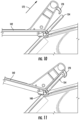
- FIGS. 10 to 12 illustrate an exemplary operation to selectively lock the locking interface 170 with the secondary handle 154.
- the locking interface 170 may be receivable within a gated opening.
- the gated opening can include a selectively movable latch which can move to permit entrance of the locking interface 170 into the opening. Upon insertion into the opening, the movable latch can be closed.
- the gated opening may allow the operator to lock the cover 142 in the open orientation without requiring a second degree of freedom.
- the operation of locking the cover 142 includes moving the cover 142 in a manner including a second degree of freedom in addition to rotating the cover 142 about the pivot axis 148. That is, referring to FIGS. 9 to 11 , the cover 142 may be moved in a manner other than the aforementioned rotation about the pivot axis 148.
- the cover is prepared to engage with the secondary handle 154 through a translational movement. More particularly, the cover 142 is translated in a direction generally along arrowed line 172 ( FIG. 10 ). The cover 142 can be translated in the direction of the arrowed line 172 a distance sufficient to allow the locking interface 170 to align with the secondary handle 154. That is, the cover 142 can be translated until the locking interface 170 passes the secondary handle 154.
- the cover 142 can be pivoted, e.g., about pivot axis 148 (which may now be displaced in the direction of the arrowed line 172), until the locking interface 170 is aligned (e.g., overlaps) with the secondary handle 154.
- the cover 142 can be translated in a direction generally along arrowed line 174 ( FIG. 12 ). More particularly, the cover 142 is translated in the direction of the arrowed line 174 a distance sufficient to allow the locking interface 170 to selectively lock with the secondary handle 154. At this point, the cover 142 is locked in the open orientation and the operator can empty the attachment 120 through the opening 140.
- the cover 142 can be reoriented to the closed orientation using the reverse operation described above with respect to FIGS. 8 to 12 .
- the cover 142 may be oriented to the closed orientation using a different operation than that described above with respect to FIGS. 8 to 12 .
- the operation of closing the cover 142 may include use of latches, switches, rotational cams or mechanism, or the like which was not required in the original opening operation.
- the operator may empty the attachment 120 without locking the cover 142 in the open orientation. That is, the cover 142 can be rotated open without being positively locked in the open orientation.
- the cover 142 can be maintained in the closed orientation by engagement of the attachment 120 with the lawn mower 100. That is, the cover 142 may be prohibited from rotating to the open orientation by one or more features of the lawn mower 100 which restrict movement of the cover 142 when the cover 142 is engaged with the lawn mower 100.
- FIG. 13 illustrates an exemplary method 1300 of using an attachment with a lawn mower.
- the method 1300 generally includes a step 1302 of removing the attachment from the lawn mower.
- the step 1302 of removing the attachment may be performed, for example, by uncoupling one or more attachment protocol of the attachment from a mating interface of the lawn mower.
- the method 1300 can include a step 1304 of reconfiguring a cover of the attachment to an open position.
- the step 1304 of reconfiguring the cover can be performed using a single degree of freedom (e.g., rotation of the cover).
- the step 1304 of reconfiguring the cover can include a plurality of degrees of freedom, such as two degrees of freedom.
- the step 1304 of reconfiguring the cover can include both a rotational movement and a translational movement. The rotational and translational movements can occur, e.g., successively, simultaneously, or both.
- the method 1300 can further include a step 1306 of removing material from an internal volume of the attachment.
- the step 1306 can be performed after locking the cover in the open position. Locking the cover can be performed after step 1304, during step 1304, or prior to step 1306.
- emptying the attachment can include emptying material through the same opening used to fill the attachment.
- emptying the attachment may be performed using an entire size of the opening while filling the attachment can be performed using only a portion of the opening (e.g., the filling opening can be smaller than the total size of the opening such as described with respect to the openings 140 and 150).
- the method 1300 can further include a step 1308 of reconfiguring the cover to a closed position.
- the step 1308 can include unlocking the cover from the locked position.
- the method 1300 can further include a step 1310 of attaching the attachment to the lawn mower.
- the attachment may be emptied and reattached for collection of debris and other materials.
- Systems, devices, and methods described in accordance with embodiments herein may allow for collection of material (e.g., debris, clippings, etc) during operation of the lawn mower while offering easy and quick emptying and operational use.
- material e.g., debris, clippings, etc
- the attachment comprises an attachment protocol associated with attaching the attachment to the lawn mower, wherein the attachment protocol is configured to attach to a plurality of different types of lawn mowers.
- the attachment is configurable between two or more different lawn mowers, each of the two or more different lawn mowers having a different attachment protocol associated with attaching the attachment to the lawn mower.
- removing the attachment in step 1302 from the lawn mower comprises removing the attachment from a first type of lawn mower, wherein attaching the attachment to the lawn mower in step 1310 comprises attaching the attachment to a second type of lawn mower, and wherein the first and second types of lawn mowers are different from one another.
- attaching the attachment to the lawn mower in step 1310 includes moving an attachment protocol from a stored configuration to an in-use configuration.
Landscapes
- Life Sciences & Earth Sciences (AREA)
- Environmental Sciences (AREA)
- Harvester Elements (AREA)
Claims (15)
- Aufsatz (120) für einen Schubrasenmäher (100), wobei der Aufsatz (120) umfasst:einen Körper (126) mit einer oder mehreren Seitenwänden (128, 130, 132, 134, 136), die ein Innenvolumen (138) definieren, das zur Aufnahme von Schnittgut aus dem Rasenmäher (100) ausgebildet ist, wobei der Körper (126) eine Öffnung (140) definiert; undeine Abdeckung (142), die an der Öffnung (140) mit dem Körper (126) verbunden ist und zwischen einer offenen Position, in der die Öffnung (140) offen ist, und einer geschlossenen Position, in der die Öffnung (140) geschlossen ist, bewegbar ist, dadurch gekennzeichnet, dass die Abdeckung (142) in der offenen Position wahlweise verriegelbar ist, und dass die Abdeckung (142) durch eine Feder in die geschlossene Position vorgespannt ist.
- Aufsatz (120) nach Anspruch 1, wobei der Körper (125) eine starre Konstruktion aufweist, und wobei der Aufsatz (120) ferner einen Beutel umfasst, der in das Innenvolumen (138) einsetzbar und zur Aufnahme des Schnittguts konfiguriert ist.
- Aufsatz (120) nach einem der Ansprüche 1 oder 2, wobei die Abdeckung (142) eine Füllöffnung (150) aufweist, die so konfiguriert ist, dass sie in offener Verbindung mit einer Abfallauslassstelle des Rasenmähers (100) steht.
- Aufsatz (120) nach einem der Ansprüche 1, 2 oder 3, wobei die Abdeckung (142) schwenkbar mit dem Körper (126) verbunden und so konfiguriert ist, dass sie zwischen der offenen und der geschlossenen Position schwenkbar ist, und wobei die Abdeckung (142) mindestens einen zusätzlichen Freiheitsgrad aufweist, der mit dem Schwenken zwischen der offenen und der geschlossenen Position verknüpft ist.
- Aufsatz (120) nach einem der Ansprüche 1, 2, 3 oder 4, wobei der Aufsatz (120) ein Befestigungsprotokoll (158) umfasst, das so konfiguriert ist, dass es mit einer passenden Schnittstelle (164, 164A, 164B) des Rasenmähers (100) koppelt, um den Aufsatz (120) gekoppelt in einer relativ festen Position in Bezug auf den Rasenmäher (100) zu halten, und wobei das Befestigungsprotokoll (158) relativ zur Abdeckung (142) neu positionierbar ist, um mit verschiedenen passenden Schnittstellen zu korrespondieren.
- Aufsatz (120) nach Anspruch 5, wobei das Befestigungsprotokoll (158) zwischen einer Lagerkonfiguration und einer Gebrauchskonfiguration bewegbar ist.
- Aufsatz (120) nach einem der Ansprüche 1, 2, 3, 4, 5 oder 6, wobei der Aufsatz (120) abnehmbar an dem Rasenmäher (100) befestigbar ist, und wobei die Abdeckung (142) in der geschlossenen Position ist, wenn der Aufsatz (120) an dem Rasenmäher (100) befestigt ist.
- Rasenmäher (100), umfassend:ein Mähwerk (102), das einen Mähbereich (104) definiert;ein Schneidwerkzeug, das im Mähbereich (104) angeordnet ist;eine Abfallauslassstelle, die mit dem Mähbereich (104) in Verbindung steht; undeinen Aufsatz (120) gemäß Anspruch 1.
- Rasenmäher (100) nach Anspruch 8, wobei der Aufsatz (120) so konfiguriert ist, dass er Schnittgut aus dem Mähbereich (104) aufnimmt, wenn sich die Abdeckung (142) in der geschlossenen Position befindet.
- Rasenmäher (100) nach einem der Ansprüche 8 oder 9, wobei die Abdeckung (142) eine Füllöffnung (150) umfasst, die so konfiguriert ist, dass sie in offener Verbindung mit der Abfallauslassstelle des Rasenmähers (100) steht.
- Rasenmäher (100) nach einem der Ansprüche 8, 9 oder 10, wobei der Aufsatz (120) abnehmbar an dem Rasenmäher (100) befestigbar ist, und wobei die Abdeckung (142) in der geschlossenen Position ist, wenn der Aufsatz (120) an dem Rasenmäher (100) befestigt ist.
- Rasenmäher (100) nach einem der Ansprüche 8, 9, 10 oder 11, wobei der Rasenmäher (100) mindestens eine passende Schnittstelle (164, 164A, 164B) umfasst und der Aufsatz (120) ein Befestigungsprotokoll (158) umfasst, das so konfiguriert ist, dass es mit der passenden Schnittstelle (164, 164A, 164B) des Rasenmähers (100) koppelt, um den Aufsatz (120) in einer relativ festen Position in Bezug auf den Rasenmäher (100) zu halten, und wobei das Aufsatzprotokoll (158) relativ zur Abdeckung (142) neu positionierbar ist, um mit den jeweiligen passenden Schnittstellen (164, 164A, 164B) von zwei oder mehr verschiedenen Rasenmähern (100) zu korrespondieren.
- Rasenmäher (100) nach einem der Ansprüche 8, 9, 10, 11 oder 12, wobei der Körper (126) eine starre Konstruktion umfasst, und wobei der Aufsatz (120) ferner einen Beutel umfasst, der in das Innenvolumen (138) einsetzbar und zur Aufnahme des Schnittguts konfiguriert ist.
- Rasenmäher (100) nach einem der Ansprüche 8, 9, 10, 11, 12 oder 13, wobei die Abdeckung (142) schwenkbar mit dem Körper (126) verbunden und so konfiguriert ist, dass sie zwischen der offenen und der geschlossenen Position schwenkbar ist, und wobei die Abdeckung (142) mindestens einen zusätzlichen Freiheitsgrad aufweist, der mit dem Schwenken zwischen der offenen und der geschlossenen Position verbunden ist.
- Rasenmäher (100) nach einem der Ansprüche 8, 9, 10, 11, 12, 13 oder 14, wobei:der Aufsatz (120) eine erste Größe (122) definiert, gemessen von einer Draufsicht;der Rasenmäher (100) ferner einen Griff (110) umfasst, der eine zweite Größe (124) definiert, gemessen von der Draufsicht; unddie erste Größe (122) kleiner ist als die zweite Größe (124).
Applications Claiming Priority (1)
| Application Number | Priority Date | Filing Date | Title |
|---|---|---|---|
| US17/381,820 US12022773B2 (en) | 2021-07-21 | 2021-07-21 | Lawn mower and associated attachment |
Publications (3)
| Publication Number | Publication Date |
|---|---|
| EP4122310A1 EP4122310A1 (de) | 2023-01-25 |
| EP4122310C0 EP4122310C0 (de) | 2025-07-09 |
| EP4122310B1 true EP4122310B1 (de) | 2025-07-09 |
Family
ID=82611187
Family Applications (1)
| Application Number | Title | Priority Date | Filing Date |
|---|---|---|---|
| EP22185403.7A Active EP4122310B1 (de) | 2021-07-21 | 2022-07-18 | Rasenmäher und zugehörige befestigung |
Country Status (6)
| Country | Link |
|---|---|
| US (1) | US12022773B2 (de) |
| EP (1) | EP4122310B1 (de) |
| CN (1) | CN115669358A (de) |
| AU (1) | AU2022205268A1 (de) |
| CA (1) | CA3168249A1 (de) |
| MX (1) | MX2022008958A (de) |
Families Citing this family (1)
| Publication number | Priority date | Publication date | Assignee | Title |
|---|---|---|---|---|
| US12022773B2 (en) * | 2021-07-21 | 2024-07-02 | Techtronic Cordless Gp | Lawn mower and associated attachment |
Family Cites Families (56)
| Publication number | Priority date | Publication date | Assignee | Title |
|---|---|---|---|---|
| GB892309A (en) | 1959-11-06 | 1962-03-28 | Theodor William Reinhold | Improvements in and relating to grass catchers for rotary-scythe mowers |
| US3099123A (en) * | 1961-04-17 | 1963-07-30 | Jacobsen Mfg Co | Rotary lawn mower hinged grass catching chute |
| US3110998A (en) * | 1962-03-05 | 1963-11-19 | Pioneer Gen E Motor Corp | Lawn mower receptacle system for clippings, leaves and the like |
| US3408801A (en) * | 1965-10-22 | 1968-11-05 | Toro Mfg Corp | Non-spill grass catcher |
| DE1582482A1 (de) * | 1966-12-06 | 1970-06-11 | Wolf Elmar Joseph | Anordnung mit Grasfangkorb und Transportgestell fuer Rasenmaeher |
| GB1176634A (en) * | 1968-02-08 | 1970-01-07 | G D Mountfield Ltd | Improvements in Grass Boxes for Rotary Mowers. |
| US3872656A (en) * | 1973-08-27 | 1975-03-25 | Outboard Marine Corp | Safety shutter door assembly for rotary lawnmower grass catcher chute |
| CA1036366A (en) * | 1973-08-27 | 1978-08-15 | Einar S. Dahl | Safety shutter door assembly for rotary lawnmower grass catcher chute |
| US3893284A (en) * | 1973-12-20 | 1975-07-08 | Mtd Products Inc | Lawn mower and collector therefor |
| US4054023A (en) * | 1974-09-05 | 1977-10-18 | Outboard Marine Corporation | Grass collection apparatus |
| US4149362A (en) | 1977-07-25 | 1979-04-17 | Jacobsen Manufacturing Company | Combined lawn mower and grass catcher |
| US4149363A (en) | 1977-07-25 | 1979-04-17 | Jacobsen Manufacturing Company | Lawn mower catcher |
| FR2437154A1 (fr) * | 1978-09-28 | 1980-04-25 | Wolf Outils | Dispositif de reception de l'herbe coupee par une tondeuse a gazon |
| US4214424A (en) | 1979-01-22 | 1980-07-29 | Roper Corporation | Catcher securement for rear bagger |
| US4306408A (en) | 1980-07-15 | 1981-12-22 | The Toro Company | Grass catcher assembly |
| DE3033345A1 (de) | 1980-09-04 | 1982-04-01 | Wolf-Geräte GmbH, 5240 Betzdorf | Sichelrasenmaeher mit heckauswurf |
| US4800712A (en) * | 1982-08-04 | 1989-01-31 | Outboard Marine Corporation | Grass catcher mounting system |
| DE3328081C1 (de) * | 1983-08-03 | 1984-03-29 | Sabo-Maschinenfabrik Gmbh & Co Kg, 5270 Gummersbach | Fangvorrichtung fuer das Schnittgut eines Rasenmaehers |
| US4566257A (en) * | 1984-06-29 | 1986-01-28 | Mohammad Akrabawi | Lawn mower disposable grass collection bag attachment |
| JPH0228674Y2 (de) | 1985-02-01 | 1990-08-01 | ||
| JPS62259505A (ja) * | 1986-05-02 | 1987-11-11 | 株式会社クボタ | 芝刈機の集草バツグ |
| DE3741019A1 (de) | 1987-12-03 | 1989-06-15 | Wolf Geraete Gmbh | Grasfangvorrichtung fuer rasenmaeher |
| US4907403A (en) * | 1989-02-06 | 1990-03-13 | Otis Jones | Grass mower improvement |
| FR2703211B1 (fr) * | 1993-04-02 | 1995-05-24 | Charpenet Louis Joseph | Dispositif de stockage pour appareil pour le ramassage du gazon, feuilles mortes et autres salissures du sol. |
| FR2715021B1 (fr) * | 1994-01-20 | 1996-03-08 | Delery Creations | Bac de récupération et de stockage pour tondeuse à gazon ou matériel similaire. |
| US5794425A (en) * | 1996-09-05 | 1998-08-18 | Mtd Products Inc. | Lawn debris collecting system and method |
| US5845473A (en) | 1997-06-09 | 1998-12-08 | Deere & Company | Material collection bag |
| DE20021721U1 (de) * | 2000-11-22 | 2001-04-19 | Czeban, William F., 74653 Künzelsau | Rasenmähvorrichtung mit integrierten Mehrfachfunktionen |
| GB0125225D0 (en) | 2001-10-19 | 2001-12-12 | Electrolux Outdoor Prod Ltd | Lawnmower |
| JP3741643B2 (ja) | 2001-12-04 | 2006-02-01 | 株式会社クボタ | 草刈機の集草容器取り付け構造 |
| JP3776071B2 (ja) | 2002-09-26 | 2006-05-17 | 株式会社クボタ | 集草装置及びこの集草装置を備えた草刈機 |
| GB2395884B (en) * | 2002-12-05 | 2006-04-12 | Electrolux Outdoor Prod Ltd | Lawnmower |
| US7013627B2 (en) * | 2003-09-12 | 2006-03-21 | Ariens Company | Bagging device for a lawnmower |
| US6996963B2 (en) * | 2003-11-25 | 2006-02-14 | Ariens Company | Utility cart for use on a lawnmower |
| US7806593B2 (en) | 2005-02-03 | 2010-10-05 | Todd Toporski | Refuse bag with improved air removal and content compaction |
| GB0503859D0 (en) * | 2005-02-25 | 2005-04-06 | Gmca Pty Ltd | Lawn mower |
| US7185478B1 (en) | 2005-04-28 | 2007-03-06 | Willis Ii Hulen J | Automated lawn cutting and vacuum system |
| GB2429624B (en) * | 2005-08-31 | 2008-02-06 | Husqvarna Uk Ltd | Lawnmower |
| US8033086B2 (en) | 2007-05-01 | 2011-10-11 | Yanmar Co., Ltd. | Lawn mower with grass collection box |
| CN201150509Y (zh) * | 2008-01-16 | 2008-11-19 | 泰怡凯电器(苏州)有限公司 | 一种灰尘收集装置 |
| US20110197559A1 (en) | 2010-02-17 | 2011-08-18 | Marcus Gordon BIRCH | Grass collection container for lawn mower |
| US9084393B1 (en) * | 2012-03-27 | 2015-07-21 | Andrew M. Singleton | Lawn equipment attachment |
| CN203353174U (zh) | 2013-06-05 | 2013-12-25 | 浙江捷灵机械有限公司 | 割草机上的草箱结构 |
| CN203467222U (zh) | 2013-09-02 | 2014-03-12 | 苏州金莱克精密机械有限公司 | 含有集草箱的电动工具及其集草箱 |
| CN203597086U (zh) | 2013-11-14 | 2014-05-21 | 昌吉州西域金马农业机械制造有限责任公司 | 自卸草箱的延伸板 |
| CN104871719B (zh) | 2014-02-28 | 2017-08-22 | 苏州宝时得电动工具有限公司 | 割草机 |
| US10721866B2 (en) * | 2015-05-18 | 2020-07-28 | Husqvarna Ab | Walk behind lawn mower with a collector dump assembly |
| US10624265B2 (en) | 2016-09-01 | 2020-04-21 | The Toro Company | Bagger for stand-on mower |
| CN206506880U (zh) | 2016-12-02 | 2017-09-22 | 浙江亚特电器有限公司 | 一种方便清理出草口的割草机 |
| CN106717494B (zh) | 2016-12-02 | 2023-04-07 | 浙江亚特电器股份有限公司 | 一种方便清理出草口的割草机 |
| JP7009886B2 (ja) | 2017-09-28 | 2022-01-26 | 井関農機株式会社 | 乗用草刈り機 |
| CN207573941U (zh) | 2017-11-14 | 2018-07-06 | 南京德朔实业有限公司 | 一种用于割草机的防尘袋 |
| CN208874860U (zh) | 2018-08-30 | 2019-05-21 | 杭州慧慧科技有限公司 | 割草机壳体及割草机 |
| EP3738425B1 (de) * | 2019-05-17 | 2022-02-23 | Andreas Stihl AG & Co. KG | Rasenmäher |
| US11716932B2 (en) * | 2020-02-19 | 2023-08-08 | Excel Industries, Inc. | Side-discharge to bagging conversion assembly for mower |
| US12022773B2 (en) * | 2021-07-21 | 2024-07-02 | Techtronic Cordless Gp | Lawn mower and associated attachment |
-
2021
- 2021-07-21 US US17/381,820 patent/US12022773B2/en active Active
-
2022
- 2022-07-15 AU AU2022205268A patent/AU2022205268A1/en active Pending
- 2022-07-18 EP EP22185403.7A patent/EP4122310B1/de active Active
- 2022-07-19 CA CA3168249A patent/CA3168249A1/en active Pending
- 2022-07-20 MX MX2022008958A patent/MX2022008958A/es unknown
- 2022-07-21 CN CN202210859383.2A patent/CN115669358A/zh active Pending
Also Published As
| Publication number | Publication date |
|---|---|
| AU2022205268A1 (en) | 2023-02-09 |
| EP4122310C0 (de) | 2025-07-09 |
| CA3168249A1 (en) | 2023-01-21 |
| EP4122310A1 (de) | 2023-01-25 |
| MX2022008958A (es) | 2023-01-23 |
| US20230023352A1 (en) | 2023-01-26 |
| CN115669358A (zh) | 2023-02-03 |
| US12022773B2 (en) | 2024-07-02 |
Similar Documents
| Publication | Publication Date | Title |
|---|---|---|
| US6050072A (en) | Riding lawnmower comprising particularly a collector for cut grass | |
| EP4122310B1 (de) | Rasenmäher und zugehörige befestigung | |
| US7204073B1 (en) | Convertible mower deck with interlocking baffles | |
| US4478031A (en) | Lawnmowers with rotatable cutting blades | |
| US7677022B2 (en) | Convertible mower deck with angled pivoting baffles | |
| EP1512319B1 (de) | Rasenmäher | |
| EP3437453B1 (de) | Aufsitzrasenmäher | |
| EP1819487A1 (de) | Mobiles antriebsaggregat | |
| US20240122099A1 (en) | Walk behind power tools | |
| US7051504B2 (en) | Movable chute apparatuses and methods for a mowing machine | |
| US6694716B1 (en) | Mowing machine chute cleaner apparatus and method | |
| US9043957B2 (en) | Movable door apparatuses and methods for a combination grass discharge and mulching lawnmower | |
| US6996963B2 (en) | Utility cart for use on a lawnmower | |
| DE102020105612A1 (de) | Standstaubsauger | |
| US20210251143A1 (en) | Side-discharge to bagging conversion assembly for mower | |
| US4084284A (en) | Lawn and yard implement | |
| JP7077160B2 (ja) | 芝刈機 | |
| US20050055994A1 (en) | Bagging device for a lawnmower | |
| EP4098100B1 (de) | Elektrowerkzeug | |
| EP3297416B1 (de) | Handgeführter rasenmäher mit einer sammelmuldenanordnung | |
| CN1823566B (zh) | 割草机 | |
| EP3453645A1 (de) | Behälter zum sammeln von hausmüll, ausgestattet mit rädern und anhebe- und manövrierungsmitteln | |
| EP4245113A1 (de) | Rasenmäher und zugehörige funktionen | |
| JP2830238B2 (ja) | 草刈機における刈草収容装置 | |
| EP0419176B1 (de) | Grasfangbehälter für Rasenmäher |
Legal Events
| Date | Code | Title | Description |
|---|---|---|---|
| PUAI | Public reference made under article 153(3) epc to a published international application that has entered the european phase |
Free format text: ORIGINAL CODE: 0009012 |
|
| STAA | Information on the status of an ep patent application or granted ep patent |
Free format text: STATUS: THE APPLICATION HAS BEEN PUBLISHED |
|
| AK | Designated contracting states |
Kind code of ref document: A1 Designated state(s): AL AT BE BG CH CY CZ DE DK EE ES FI FR GB GR HR HU IE IS IT LI LT LU LV MC MK MT NL NO PL PT RO RS SE SI SK SM TR |
|
| STAA | Information on the status of an ep patent application or granted ep patent |
Free format text: STATUS: REQUEST FOR EXAMINATION WAS MADE |
|
| 17P | Request for examination filed |
Effective date: 20230725 |
|
| RBV | Designated contracting states (corrected) |
Designated state(s): AL AT BE BG CH CY CZ DE DK EE ES FI FR GB GR HR HU IE IS IT LI LT LU LV MC MK MT NL NO PL PT RO RS SE SI SK SM TR |
|
| GRAP | Despatch of communication of intention to grant a patent |
Free format text: ORIGINAL CODE: EPIDOSNIGR1 |
|
| STAA | Information on the status of an ep patent application or granted ep patent |
Free format text: STATUS: GRANT OF PATENT IS INTENDED |
|
| INTG | Intention to grant announced |
Effective date: 20240913 |
|
| GRAJ | Information related to disapproval of communication of intention to grant by the applicant or resumption of examination proceedings by the epo deleted |
Free format text: ORIGINAL CODE: EPIDOSDIGR1 |
|
| STAA | Information on the status of an ep patent application or granted ep patent |
Free format text: STATUS: REQUEST FOR EXAMINATION WAS MADE |
|
| INTC | Intention to grant announced (deleted) | ||
| GRAP | Despatch of communication of intention to grant a patent |
Free format text: ORIGINAL CODE: EPIDOSNIGR1 |
|
| STAA | Information on the status of an ep patent application or granted ep patent |
Free format text: STATUS: GRANT OF PATENT IS INTENDED |
|
| INTG | Intention to grant announced |
Effective date: 20250210 |
|
| GRAS | Grant fee paid |
Free format text: ORIGINAL CODE: EPIDOSNIGR3 |
|
| GRAA | (expected) grant |
Free format text: ORIGINAL CODE: 0009210 |
|
| STAA | Information on the status of an ep patent application or granted ep patent |
Free format text: STATUS: THE PATENT HAS BEEN GRANTED |
|
| AK | Designated contracting states |
Kind code of ref document: B1 Designated state(s): AL AT BE BG CH CY CZ DE DK EE ES FI FR GB GR HR HU IE IS IT LI LT LU LV MC MK MT NL NO PL PT RO RS SE SI SK SM TR |
|
| REG | Reference to a national code |
Ref country code: GB Ref legal event code: FG4D |
|
| REG | Reference to a national code |
Ref country code: CH Ref legal event code: EP |
|
| REG | Reference to a national code |
Ref country code: IE Ref legal event code: FG4D |
|
| REG | Reference to a national code |
Ref country code: DE Ref legal event code: R096 Ref document number: 602022017207 Country of ref document: DE |
|
| U01 | Request for unitary effect filed |
Effective date: 20250805 |
|
| U07 | Unitary effect registered |
Designated state(s): AT BE BG DE DK EE FI FR IT LT LU LV MT NL PT RO SE SI Effective date: 20250814 |
|
| U20 | Renewal fee for the european patent with unitary effect paid |
Year of fee payment: 4 Effective date: 20250813 |
|
| PG25 | Lapsed in a contracting state [announced via postgrant information from national office to epo] |
Ref country code: IS Free format text: LAPSE BECAUSE OF FAILURE TO SUBMIT A TRANSLATION OF THE DESCRIPTION OR TO PAY THE FEE WITHIN THE PRESCRIBED TIME-LIMIT Effective date: 20251109 |
|
| PG25 | Lapsed in a contracting state [announced via postgrant information from national office to epo] |
Ref country code: NO Free format text: LAPSE BECAUSE OF FAILURE TO SUBMIT A TRANSLATION OF THE DESCRIPTION OR TO PAY THE FEE WITHIN THE PRESCRIBED TIME-LIMIT Effective date: 20251009 |
|
| PG25 | Lapsed in a contracting state [announced via postgrant information from national office to epo] |
Ref country code: HR Free format text: LAPSE BECAUSE OF FAILURE TO SUBMIT A TRANSLATION OF THE DESCRIPTION OR TO PAY THE FEE WITHIN THE PRESCRIBED TIME-LIMIT Effective date: 20250709 |
|
| PG25 | Lapsed in a contracting state [announced via postgrant information from national office to epo] |
Ref country code: GR Free format text: LAPSE BECAUSE OF FAILURE TO SUBMIT A TRANSLATION OF THE DESCRIPTION OR TO PAY THE FEE WITHIN THE PRESCRIBED TIME-LIMIT Effective date: 20251010 |
|
| PG25 | Lapsed in a contracting state [announced via postgrant information from national office to epo] |
Ref country code: PL Free format text: LAPSE BECAUSE OF FAILURE TO SUBMIT A TRANSLATION OF THE DESCRIPTION OR TO PAY THE FEE WITHIN THE PRESCRIBED TIME-LIMIT Effective date: 20250709 |
|
| PG25 | Lapsed in a contracting state [announced via postgrant information from national office to epo] |
Ref country code: RS Free format text: LAPSE BECAUSE OF FAILURE TO SUBMIT A TRANSLATION OF THE DESCRIPTION OR TO PAY THE FEE WITHIN THE PRESCRIBED TIME-LIMIT Effective date: 20251009 |
|
| PG25 | Lapsed in a contracting state [announced via postgrant information from national office to epo] |
Ref country code: ES Free format text: LAPSE BECAUSE OF FAILURE TO SUBMIT A TRANSLATION OF THE DESCRIPTION OR TO PAY THE FEE WITHIN THE PRESCRIBED TIME-LIMIT Effective date: 20250709 |
|
| REG | Reference to a national code |
Ref country code: CH Ref legal event code: H13 Free format text: ST27 STATUS EVENT CODE: U-0-0-H10-H13 (AS PROVIDED BY THE NATIONAL OFFICE) Effective date: 20260224 |
|
| PG25 | Lapsed in a contracting state [announced via postgrant information from national office to epo] |
Ref country code: SM Free format text: LAPSE BECAUSE OF FAILURE TO SUBMIT A TRANSLATION OF THE DESCRIPTION OR TO PAY THE FEE WITHIN THE PRESCRIBED TIME-LIMIT Effective date: 20250709 |
|
| PGFP | Annual fee paid to national office [announced via postgrant information from national office to epo] |
Ref country code: AT Payment date: 20260410 Year of fee payment: 4 |