EP4121901B1 - Closure element - Google Patents
Closure element Download PDFInfo
- Publication number
- EP4121901B1 EP4121901B1 EP20714167.2A EP20714167A EP4121901B1 EP 4121901 B1 EP4121901 B1 EP 4121901B1 EP 20714167 A EP20714167 A EP 20714167A EP 4121901 B1 EP4121901 B1 EP 4121901B1
- Authority
- EP
- European Patent Office
- Prior art keywords
- cap member
- inner cap
- closure element
- capacitor
- top wall
- Prior art date
- Legal status (The legal status is an assumption and is not a legal conclusion. Google has not performed a legal analysis and makes no representation as to the accuracy of the status listed.)
- Active
Links
Images


Classifications
-
- G—PHYSICS
- G06—COMPUTING OR CALCULATING; COUNTING
- G06K—GRAPHICAL DATA READING; PRESENTATION OF DATA; RECORD CARRIERS; HANDLING RECORD CARRIERS
- G06K19/00—Record carriers for use with machines and with at least a part designed to carry digital markings
- G06K19/06—Record carriers for use with machines and with at least a part designed to carry digital markings characterised by the kind of the digital marking, e.g. shape, nature, code
- G06K19/067—Record carriers with conductive marks, printed circuits or semiconductor circuit elements, e.g. credit or identity cards also with resonating or responding marks without active components
- G06K19/07—Record carriers with conductive marks, printed circuits or semiconductor circuit elements, e.g. credit or identity cards also with resonating or responding marks without active components with integrated circuit chips
- G06K19/077—Constructional details, e.g. mounting of circuits in the carrier
- G06K19/07749—Constructional details, e.g. mounting of circuits in the carrier the record carrier being capable of non-contact communication, e.g. constructional details of the antenna of a non-contact smart card
-
- B—PERFORMING OPERATIONS; TRANSPORTING
- B65—CONVEYING; PACKING; STORING; HANDLING THIN OR FILAMENTARY MATERIAL
- B65D—CONTAINERS FOR STORAGE OR TRANSPORT OF ARTICLES OR MATERIALS, e.g. BAGS, BARRELS, BOTTLES, BOXES, CANS, CARTONS, CRATES, DRUMS, JARS, TANKS, HOPPERS, FORWARDING CONTAINERS; ACCESSORIES, CLOSURES, OR FITTINGS THEREFOR; PACKAGING ELEMENTS; PACKAGES
- B65D51/00—Closures not otherwise provided for
- B65D51/24—Closures not otherwise provided for combined or co-operating with auxiliary devices for non-closing purposes
- B65D51/245—Closures not otherwise provided for combined or co-operating with auxiliary devices for non-closing purposes provided with decoration, information or contents indicating devices, labels
-
- B—PERFORMING OPERATIONS; TRANSPORTING
- B65—CONVEYING; PACKING; STORING; HANDLING THIN OR FILAMENTARY MATERIAL
- B65D—CONTAINERS FOR STORAGE OR TRANSPORT OF ARTICLES OR MATERIALS, e.g. BAGS, BARRELS, BOTTLES, BOXES, CANS, CARTONS, CRATES, DRUMS, JARS, TANKS, HOPPERS, FORWARDING CONTAINERS; ACCESSORIES, CLOSURES, OR FITTINGS THEREFOR; PACKAGING ELEMENTS; PACKAGES
- B65D51/00—Closures not otherwise provided for
- B65D51/18—Arrangements of closures with protective outer cap-like covers or of two or more co-operating closures
-
- B—PERFORMING OPERATIONS; TRANSPORTING
- B65—CONVEYING; PACKING; STORING; HANDLING THIN OR FILAMENTARY MATERIAL
- B65D—CONTAINERS FOR STORAGE OR TRANSPORT OF ARTICLES OR MATERIALS, e.g. BAGS, BARRELS, BOTTLES, BOXES, CANS, CARTONS, CRATES, DRUMS, JARS, TANKS, HOPPERS, FORWARDING CONTAINERS; ACCESSORIES, CLOSURES, OR FITTINGS THEREFOR; PACKAGING ELEMENTS; PACKAGES
- B65D2203/00—Decoration means, markings, information elements, contents indicators
- B65D2203/10—Transponders
Definitions
- the present invention refers to a closure element for closing a container like a bottle, canister, or the like.
- closure elements having anti-tampering means are used.
- a known closure element comprises a transponder, such as an RFID tag (sometimes also called IC tag), which is modified in its structure when opened.
- RFID tag sometimes also called IC tag
- An RFID tag generally comprises a chip and an antenna, as well as sometimes a piece of control loop separately connected to the chip.
- the antenna can be interrupted so that the chip cannot be read out any more, or the piece of loop can be interrupted to thus change the state of the chip.
- the interruption of the antenna or loop is realized by rotating the closure member with the tag with respect to the neck of the bottle/neck label).
- the transponder in the RFID tag communicates its unopened state. If the transponder is interrogated after the piece of loop has been interrupted upon opening the closure, it communicates that the closure member has been opened. If the antenna has been interrupted, readout is no longer possible, and the user should be wary.
- the antenna or the control loop is interrupted by using a cutting means or the like.
- closure members like the above are complicated in manufacturing and in assembling onto the bottle or container.
- closure members as in the known closure members a mechanical break is strictly necessary to perform the anti-tempering function, a great precision in their manufacturing is necessary and, sometimes, the reliability of the closure elements is not completely satisfying.
- the cutting means has to be designed and realized with high precision to ensure that the interaction between the cutting means and the part of the RFID tag to break is effective.
- the interruption of the control loop causes a change of the properties of the closure element which can be detected by means of a suitable reader, in particular a change of the state of the chip to which the control loop is connected, and thus a change of the readout signal.
- the chip may be configured to set the status to undisturbed/disturbed in response to an undisturbed/disturbed state of the control loop.
- the status of the control loop is set to the disturbed status in response to a change in either an inductance or a capacitance of the control loop when it is cut or broken.
- EP 2 865 607 A1 is reflected in the preamble portion of claim 1.
- the subject-matter of claim 1 provides a closure element with features for addressing this object. Further preferred embodiments are mentioned in the dependent claims and/or outlined in the following description.
- the closure element further comprises at least two first capacitor plates connected with the chip, wherein the two first capacitor plates are attached to one of the top wall of the inner cap member and the top wall of the outer cap member.
- the closure element comprises at least a second capacitor plate attached to the other of the top wall of the inner cap member and the top wall of the outer cap member, in such a way that a relative movement of the outer cap member and the inner cap member switches the closure element between a first configuration in which each of the first capacitor plates and the second capacitor plate define a capacitor having a first capacitance and a second configuration in which the first capacitor plates and the second capacitor plate define a capacitor having a second capacitance different from the first one.
- each of the first capacitor plates defines a capacitor with the second capacitor plate.
- two capacitors in series are defined with a total electrical capacitance depending on the configuration of the first capacitor plates and the second capacitor plate.
- the configuration includes distance and overlap between each first capacitor plate and the second capacitor plate as well as the dielectric medium between them.
- the closure element is interrogated by means of a reader, an electrical field is defined in the capacitor and the voltage measurable at the ends of the first plates, which are connected with the RFID chip, depends on the configuration of the plates. Therefore, the information readable from the RFID chip is representative of the first or second configuration of the closure element.
- the first capacitor plates and the second capacitor plate are disposed in a first relative position and, in the second configuration, the first capacitor plates and the second capacitor plate are disposed in a second relative position which is different from the first one.
- the outer cap member and the inner cap member are rotatably coupled. This feature allows an easy way to change the relative position between the outer cap member and the inner cap member.
- the outer cap member and the inner cap member are movable along a longitudinal direction. This feature provides an alternative way to easily and quickly change the relative position between the outer cap member and the inner cap member.
- the first capacitor plates and the second capacitor plate are overlapping and, in the second relative position, the first capacitor plates and the second capacitor plate are not overlapping.
- the electrical capacitance measurable is maximum and, when the first capacitor plates and the second capacitor plate are overlapping, the electrical capacitance measurable is minimum. Therefore, the difference in electrical capacitance measurable is the highest possible and the change in configuration can be easily detected.
- the area of the two first capacitor plates, in combination, and the area of the second capacitor plate are substantially the same. This feature allows the capacitor to have a sufficiently high capacitance in order to better detect the change of configuration.
- the shape of the two first capacitor plates, in combination, and the shape of the second capacitor plate are substantially the same. Also this feature allows the capacitor to have a sufficiently high capacitance in order to better detect the change of configuration.
- each first capacitor plate comprises at least a first portion shaped as a circular sector. Due to this feature, it is possible to provide the first capacitor plates having a sufficient area in a closed and reduced space between the outer cap member and the inner cap member.
- the first portions of the first capacitor plates are next to each other on the same plane.
- the second capacitor plate comprises at least a portion shaped as a circular sector. Due to this feature, it is possible to provide the second capacitor plate having a sufficient area in a closed and reduced space between the outer cap member and the inner cap member.
- each first capacitor plate comprises a second portion having the shape of a circular sector, each first portion being concentric to the corresponding second portion, wherein each first portion is electrically connected to the respective second portion. This allows to maximize the area of the first capacitor plates in order to increase the electrical capacitance.
- the second capacitor plate comprises a plurality of portions, each portion being shaped as a circular sector; the portions being electrically connected to each other. This allows to maximize the area of the second capacitor plate in order to increase the electrical capacitance.
- the second capacitor plate in the first configuration, has a first shape and in the second configuration the second capacitor plate has a second shape which is different from the first one.
- the electrical capacitance of the capacitor defined between the first and the second plates can be changed by modifying the shape of the second plate when moving the outer cap member with reference to the inner cap member.
- the second capacitor plate comprises a plurality of capacitor portions configured to be electrically connected to each other in the first configuration and electrically disconnected in second configuration.
- the capacitor portions of the second capacitor plate which are originally connected to each other, are separated due to the relative movement of the outer cap member and the inner cap member.
- the overall area of the second capacitor plate changes, thereby modifying the electrical capacitance of the capacitor defined between the first and second capacitor plates.
- the second capacitor plate comprises a first ring attached to one of the outer cap member and the inner cap member and a second ring attached to the other of the outer cap member and the inner cap member; wherein the capacitor portions are connected between the first ring and the second ring.
- This configuration allows the capacitor portions of the second capacitor plate to be disconnected from each other due to the torque generated between the first ring and the capacitor portions, and the second ring and the capacitor portions by simply rotating the outer cap member with reference to the inner cap member.
- the portions are connected to the first ring and the second ring by means of breakable bridges. This feature allows a simple and quick separation of the portions of the second capacitor plate.
- the portions are trapezoidal-shaped and evenly angularly spaced. According to this feature, the portions can be arranged in such a way to maximize the overall area of the second capacitor plate.
- the first ring presents an edge connected to the outer cap member; the edge being shaped such that the first ring is rotatably fastened to the outer cap member; wherein the second ring presents an edge connected to the inner cap member; the edge being shaped such that the second ring is rotatably fastened to the inner cap member. Due to this feature, it is possible to determine a relative rotation between the first and the second ring while rotating the outer cap member with respect to the inner cap member. This relative rotation of the rings causes the shear action which breaks the portions from the rings. In this way, the shape and the overall area of the second capacitor plate changes, thereby modifying the electrical capacitance.
- the inner cap member presents a groove arranged between the top wall and the side wall of the inner cap member, the groove facing the outer cap member; the outer cap member comprising a tooth arranged between the top wall and the side wall of the outer cap member; the tooth being slidingly housed in the groove; wherein the groove extends only in part along the circumferential extension of the inner cap member.
- the transponder is an RFID tag; preferably the transponder being an NFC tag.
- closure element according to another aspect of the invention further comprises blocking means active between the outer cap member and the inner cap member to impede switching from the second configuration to the first configuration.
- closure element This allows the closure element to permanently inform the user that the closure element has been previously opened.
- the blocking means comprises a spacer member operatively placed between the outer cap member and the inner cap member; the spacer member being switchable from a first arrangement in which it is fitted in a cavity formed at a joining portion between the top wall and the side wall of the inner cap member to a second arrangement in which the spacer member lies between the top wall of the inner cap member and the top wall of the outer cap member.
- Figures 1 and 2 show a closure element 10 comprising an outer cap member 20 and an inner cap member 30 coupled with the outer cap member 20.
- the inner cap member 30 is to be coupled with a mouth of a container (not shown) in a rotatably fixed manner.
- the inner cup portion 30 comprises a screw portion 34 for coupling with the mouth of the container.
- the outer cap member 20 comprises a top wall 21, preferably of circular shape, and a side wall 22, preferably of cylindrical shape, extending from an edge of the top wall 21.
- the inner cap member 30 comprises a top wall 31, preferably of circular shape, and a side wall 32, preferably of cylindrical shape, extending from an edge of the top wall 31.
- the screw portion 34 is realised on the inside of the side wall 32 of the inner cap member 30.
- the outer cap member 20 is rotatably coupled to the inner cap member 30 in such a way that the outer cap member 20 can rotate with reference to the inner cap member 30 for a first part of its movement and then, after the outer cap member 20 engages the inner cap member 30, both the outer cap member 20 and the inner cap member 30 rotate together in a second part of the movement to unscrew the closure element 10.
- the inner cap member 30 presents at least a groove 33 arranged between the top wall 31 and the side wall 32 thereof.
- the groove 33 extends only in part along the circumferential extension of the inner cap member 30.
- the inner cap member 30 presents a plurality of grooves 33, each having the same length. They may also be evenly angularly spaced, i.e. arranged in equal intervals around the circumference of the inner cap member 30.
- the grooves 33 face the outer cap member 20.
- the grooves 33 face a junction zone between the top wall 21 and the side wall 22 of the outer cap member 20.
- the outer cap member 20 comprises at least a tooth 23 arranged between the top wall 21 and the side wall 22 thereof (see Fig. 1b ).
- the outer cap member 20 comprises a plurality of teeth 23 which are evenly angularly spaced.
- Each tooth 23 is housed in a corresponding groove 33 in such a way that it can slide along the groove 33.
- the outer cap member 20 engages the inner cap member 30 and the outer cap member 20 transmits the rotation movement to the inner cap member 30 to unscrew the closure element 10 and open the container.
- the closure element 10 further comprises a transponder 40 housed between the inner cap member 30 and the outer cap member 20.
- the transponder 40 is arranged between the top wall 21 of the outer cap member 20 and the top wall 31 of the inner cap member 30.
- the transponder 40 can be active or passive.
- the transponder is of the passive type.
- the transponder 40 is an RFID tag.
- the transponder 40 is an NFC ("near field communication") tag.
- An NFC tag is based on high frequency (HF)-RFID technology but operates only on very short ranges (of the order of a few centimetres).
- the transponder 40 comprises a chip 41 and an antenna 42.
- the chip 41 and the antenna 42 of the transponder 40 are attached to one of the top wall 31 of the inner cap member 30 and the top wall 21 of the outer cap member 20.
- the antenna 42 is arranged in such a way to lie in a C-shaped area.
- the transponder 40 and in particular the chip 41 and the antenna 42 are directly attached to the top wall 31 of the inner cap member 30.
- the chip 41 and the antenna 42 of the transponder 40 are directly printed on the top wall 31 of the inner cap member 30.
- the closure element 10 further comprises two first capacitor plates 50, 51.
- the first capacitor plates 50, 51 are arranged on one of the top wall 21 of the outer cap member 20 and the top wall 31 of the inner cap member 30.
- the first capacitor plates 50, 51 are arranged on the same top wall where the chip 41 and the antenna 42 of the transponder 40 are placed.
- the first capacitor plates 50, 51 are arranged on the top wall 31 of the inner cap member 30.
- the first capacitor plates 50, 51 are directly arranged on the top wall 31 of the inner cap member 30.
- the first capacitor plates 50, 51 are directly printed on the top wall 31 of the inner cap member 30.
- Each first capacitor plate 50, 51 is directly and individually connected to the chip 41 of the transponder 40.
- the closure element 10 further comprises at least a second capacitor plate 52 arranged on the other of the top wall 31 of the inner cap member 30 and the top wall 21 of the outer cap member 20.
- the second capacitor plate 52 is arranged on the top wall 21 of the outer cap member 20.
- the second capacitor plate 52 is arranged on a surface of the top wall 21 of the outer cap member 20 facing a surface of the top wall 31 of the inner cap member 30 housing the transponder 40.
- the first capacitor plates 50, 51 together with the transponder 40 may be placed on the top wall 21 of the outer cap member 20 and the second capacitor plate 52 are arranged on the top wall 31 of the inner cap member 30.
- the relative rotation of the outer cap member 20 with respect to the inner cap member 30 determines a modification of the relative position between the first capacitor plates 50, 51 and the second capacitor plate 52.
- the closure element 10 is switched between a first configuration in which the first capacitor plates 50, 51 and the second capacitor plate 52 are in a first relative position and a second configuration in which the first capacitor plates 50, 51 and the second capacitor plate 52 are in a second relative position.
- the first configuration can be representative of a closed configuration of the closing element 10
- the second configuration can be representative of an opened configuration of the closing element 10.
- the switching of the closing element 10 from the first to the second configuration is representative of the fact that the container has been previously opened.
- the intensity of the electrical field depends on the capacitance of the capacitor defined by the first capacitor plates 50, 51 and the second capacitor plate 52.
- the capacitance depends on a plurality of factors as, for example, the materials and shapes of the plates, the material of the dielectric between the plates.
- the only variable factor determining the capacitance is the relative position between the plates.
- the electrical field between the plates 50, 51, 52 determines a certain voltage at the ends of the first capacitor plates 50, 51 connected to the chip 41 of the transponder 40.
- the voltage is a function of the relative position between the first capacitor plates 50, 51 and the second capacitor plate 52.
- the voltage at the ends of the first capacitor plates 50, 51 modifies the response that the transponder 40 is able to send when interrogated by the reader.
- the response read by the reader is a function of the relative position between the first capacitor plates 50, 51 and the second capacitor plate 52.
- the reader is able to identify the closed configuration and the opened configuration.
- closure element 10 of the first embodiment further comprises blocking means 60 to impede the closure element 10 to be returned to the first configuration, once the switching from the first configuration to the second configuration has been performed.
- the blocking means 60 comprises blocking ribs 61 protruding in the grooves 33 arranged between the top wall 31 and the side wall 32 of the inner cap member 30.
- the blocking ribs 61 are wedge-shaped, i.e. they form an inclined guide surface with respect to the tangent of the circumference of the grooves 33.
- the closure element 10 further comprises lifting means 80 to lift the outer cap member 20 with respect to the inner cap member 30 when the outer cap member 20 is rotated with respect to the inner cap member 30.
- the lifting means 80 is provided on the top wall 31 of the inner cap member 30.
- the lifting means 80 comprises at least one lifting rib 81 protruding from the top wall 31 of the inner cap member 30, the lifting rib 81 having an end.
- the lifting rib 81 is configured to be housed in a recess 82 arranged on the top wall 21 of the outer cap member 20 in the first (closed) configuration.
- the lifting rib 81 exits the recess 82, contacting the top wall 21 of the outer cap member 20, scraping against the top wall 31 and lifting the outer cap member 20 with respect to the inner cap member 30.
- the respective shapes of the lifting rib 81 and that of the recess 82 allow the lifting rib 81 to exit the recess 62.
- the lifting rib 81 is substantially wedge-shaped and extends along an arc of circle concentric to the centre of the top wall 31 of the inner cap member 30, having a length corresponding to an arc of 30°, for example.
- the lifting means 80 comprises a plurality of lifting rib 81.
- the lifting means 80 comprises three lifting ribs 81.
- the lifting ribs 81 61 are disposed alongside each other along a radial direction of the top wall 31 of the inner cap member 30.
- Each lifting rib 81 is shaped as an arc of circle concentric to each other.
- the lifting ribs 81 are arranged close to an edge of the top wall 31 of the inner cap member 30.
- the recess 82 is arranged in correspondence of the lifting ribs 81. Therefore, the recess 82 is arranged close to an edge of the top wall 21 of the outer cap member 20.
- the recess 82 comprises a ramp which allows the lifting ribs 81 to slide out of the recess 82.
- the closure element 10 preferably also comprises a cap liner 35 which is coupled to the inner cap member 30 to provide a seal between the closure element 10 and the container mouth.
- the cap liner 35 is coupled to the inner cap member 30 by means of a coupling protrusion 36 protruding from a surface of the top wall 31 opposite to a surface connected with the substrate 50.
- the outer cap member 20 and the inner cap member 30 are movable with respect to each other in a longitudinal direction.
- the outer cap member 20 and the inner cap member 30 are movable with respect to each other exclusively in a longitudinal direction.
- the longitudinal direction is defined as a direction parallel to a central axis of symmetry of the closure element 10.
- this axis coincides with the longitudinal axis of the bottle neck.
- FIG. 2a to 2c A second embodiment of the present invention is shown in Figs. 2a to 2c , with like numerals referring to like features of the first embodiment.
- the inner cap member 30 can be coupled to, in particular screwed onto the mouth of container 100, such as a bottle (see. Figs. 2b and 2c ).
- the outer cap member 20 and the inner cap member 30 are movable with respect to each other both in a rotational direction and in the longitudinal direction.
- the outer cap member 20 and the inner cap member 30 are movable with respect to each other in the longitudinal direction while rotating the outer cap member 20 with respect to the inner cap member 30, i.e., during switching from the closed configuration to the opened configuration. In this way, the distance in the longitudinal direction between the first capacitor plates 50, 51 and the second capacitor plate 52 is modified when opening the closure element 10.
- the distance between the top wall 21 of the outer cap member 20 and the top wall 31 of the inner cap member 30 increases when switching from the first (closed) configuration to the second (opened) configuration.
- the outer cap member 20 lifts with respect to the inner cap member 30 when switching from the first (closed) configuration to the second (opened) configuration.
- dogs 37 are placed on the inner cap member 30.
- the dogs 37 are placed on the side wall 32 of the inner cap member 30.
- These dogs 37 slide along corresponding thread grooves (not shown) on the inner side of side wall 22 of the outer cap member 20. These thread grooves are inclined in the sense that they follow a thread line in a way such that, when the outer cap member 20 is rotated with respect to the inner cap member 30 for opening the closure member, the outer cap member 20 is raised with respect to the inner cap member 30.
- the transponder and the first capacitor plates are arranged on a substrate 70 placed between the top wall 31 of the inner cap member 30 and the top wall 21 of the outer cap member 20.
- the substrate 70 is distinct from the top wall 31 of the inner cap member 30.
- the substrate 70 is attached to the top wall 31 of the inner cap member 30 by means of an adhesive layer.
- the closure element 10 comprises blocking means 60 to impede the closure element 10 to be brought back from the second (opened) configuration to the first (closed) configuration.
- the blocking means 60 comprises a spacer member 64, in this embodiment preferably shaped as an arc of circumference and placed between the inner cap member 30 and the outer cap member 20.
- the spacer member 64 is an elastic member which can be pretensioned.
- the spacer member is shaped like a snap ring.
- the spacer member 64 is constrained in a first arrangement when the closure element 10 is in the first configuration (see Fig. 2b ).
- the spacer member 64 is fitted in a cavity 65 formed at a portion of the inner cap member 30 corresponding to a joining portion between the top wall 31 and the side wall 32.
- the spacer member 64 When the closure element 10 is switched from the first (closed) configuration to the second (opened) configuration, the spacer member 64 is switched from the first arrangement to a second arrangement (see Fig. 2c ). In the second arrangement, the spacer member 64 lies on the top wall 31 of the inner cap member 30 in such a way that it is placed between the top wall 31 of the inner cap member 30 and the top wall 21 of the outer cap member 20.
- lifting hooks 66 internally protrude from the inner side of side wall 21 of the outer cap member 20 to contact the spacer member 64.
- the lifting hooks 66 can move within circumferential grooves 33 on the inner cap member 30.
- the outer cap member 20 is raised with respect to the inner cap member 20 by virtue of the dogs 37 that slide in the threaded recesses on the inner side of side wall 22 of the outer cap member 20. This means that also the lifting hooks rise with respect to the inner cap member 30, and thus push the spacer member 64 in cavity 65 upward.
- the spacer member 64 when the spacer member 64 is in the second arrangement, i.e., when the spacer member 64 is placed between the top walls 21 and 31, it functions as a spacer which impedes the top wall 21 of the outer cap member 20 to return back in the original position of the first configuration. In this way, the electrical capacitance of the closure element 10 cannot return back to the original value of the first (closed) configuration. Therefore, if the closure element 10 is opened (switched from the first to the second configuration), the capacitance is permanently changed, and by reading out the transponder of the closure element 10 it is possible to ascertain whether such switching of configuration - and thus an attempt to open the closure - has occurred.
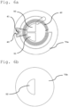
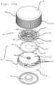
- a third embodiment is disclosed with reference to Figs. 3a and 3b .
- first configuration i.e., the closed configuration
- second configuration i.e., the opened configuration
- first capacitor plates 50, 51 and the second capacitor plate 52 are disposed in a second relative position which is different from the first one.
- the outer cap member and the inner cap member (not represented in Figs. 3a to 3d ) are rotatably coupled. Therefore, the switching from the closed configuration to the opened configuration is realized by rotating the outer cap member with respect to the inner cap member.
- the chip and the antenna of the transponder are placed on a first support 70a ( Fig. 3a ).
- the first support 70a is fixed to the top wall of the inner cap member, for example by means of an adhesive layer.
- the first support 70a is a flat element, preferably but not exclusively having a round or circular shape.
- the antenna is arranged in such a way as to lie in an O-shaped area; in the example shown in Figs. 3c and d , the antenna is substantially shaped like a circular ring.
- the first capacitor plates 50, 51 are placed on the first support 70a.
- the first capacitor plates 50, 51 are placed inside the ring-shaped antenna.
- the second capacitor plate 52 is placed on a second support 70b ( Fig. 3b ).
- the second support 70b is fixed to the top wall of the outer cap member, for example by means of an adhesive layer.
- the second support 70b is a flat element, preferably but not exclusively having a round or circular shape.
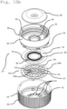
- Each of the first capacitor plates 50, 51 comprises at least a first portion 50a, 51a.
- Each first portion 50a, 51a is shaped as a circular sector.
- each of the sector-shaped first portion 50a, 51a of the capacitor plates 50, 51 is centred at the geometrical centre of the top wall of the inner cap member, i.e. the centre of the circle from which the sector-shaped portions arise coincides with the geometrical centre of the top wall.
- each first portion 50a, 51a subtends an angle of 25° to 35°.
- the angle is preferably substantially 30°.
- the first portions 50a, 51a of the first capacitor plates 50, 51 are next to each other on the same plane. In this way, for example, they both lie in a circular-sector-shaped area defining an angle of 50° to 70°. Preferably, the angle defined by both the first capacitor plates 50, 51, in combination, is substantially 60°.
- each first capacitor plates 50, 51 further comprises a second portion 51b, 51b.
- Each first portion 50a, 51a is electrically connected to a corresponding second portion 50b, 51b.
- Each second portion 50b, 51b is shaped as a circular sector. Each second portion 50b, 51b is arranged concentrically with the first portions 50a, 51a.
- each second portion 50b, 51b subtends an angle of 50° to 70°.
- the angle is preferably substantially 60°.
- Each second portion 50b, 51b is arranged at the same angle with respect to the corresponding first portion 50a, 51a. Therefore, the first capacitor plates 50, 51 are disposed in a symmetric configuration.
- each second portion 50b, 51b can be arranged at any angle with respect to the corresponding first portion 50a, 51a.
- the first capacitor plates 50, 51 can be made of any suitable, conductive material.
- the first capacitor plates 50, 51 are made of copper.
- the second capacitor plate 52 comprises at least a portion shaped as circular-sector.
- the second capacitor plate 52 comprises a plurality of portions. According to what shown, the second capacitor plate 52 comprises three portions.
- Each portion is circular-sector-shaped.
- Each portion of the second capacitor plate 52 subtends an angle of 50° to 70°. The angle is preferably substantially 60°.
- the portions of the second capacitor plate 52 are electrically connected to each other.
- the area of the first capacitor plates 50, 51, in combination, and the area of second capacitor plate 52 are substantially the same.
- the shape of the first capacitor plates 50, 51, in combination, and the shape of second capacitor plate 52 are substantially the same.
- the shape of the first capacitor plates 50, 51, in combination matches the shape of the second capacitor plate 52.
- the second capacitor plate 52 can be made of any suitable, conductive material.
- the second capacitor plate 52 is made of conductive plastic.
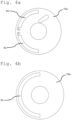
- Figs. 4a to 4d show a fourth embodiment.
- the chip and the antenna of the transponder are place on a first support 70a.
- the first support 70a is fixed to the top wall of the inner cap member (not shown), for example by means of an adhesive layer.
- the antenna is arranged in such a way to lie in an O-shaped area.
- first capacitor plates 50, 51 are placed on the first support 70a ( Fig. 4a ).
- the first capacitor plates 50, 51 are placed in an outer position with respect to the antenna.
- the first support 70a is a flat element, preferably but not exclusively, round-shaped.
- the second capacitor plate 52 is placed on a second support 70b ( Fig. 4b ).
- the second support 70b is fixed to the top wall of the outer cap member (not shown), for example by means of an adhesive layer.
- the second support 70b is a flat element, preferably but not exclusively, round-shaped.
- Each of the first capacitor plates 50, 51 are shaped as an arcuate strip.
- the first capacitor plates 50, 51 are placed at a peripheral region of the first support 70a aligned one next to the other to define an arc of circumference.
- first capacitor plates 50, 51 are preferably arranged in a concentric position with reference to a centre of the first support 70a.
- Each of the first capacitor plates 50, 51 defines an angle of 80° to 100°.
- the angle defined by each of the first capacitor plates 50, 51 is 90°.
- the second capacitor plate 52 is shaped as an arcuate strip.
- the second capacitor plate 52 is placed at a peripheral region of the second support 70b.
- the second capacitor plate 52 is preferably arranged in a concentric position with reference to a centre of the second support 70b.
- the second capacitor plate 52 defines an angle of 160° to 200°.
- the angle defined by the second capacitor plate 52 is 180°.
- the second capacitor plate 52 is overlapping both the first capacitor plates 50, 51 at a first distance.
- the second capacitor plate 52 is still overlapping both the first capacitor plates 50, 51, but at a second distance greater than the first distance.
- the relative movement between the first capacitor plates 50, 51 and the second capacitor plate 52 is a linear movement along the longitudinal direction.
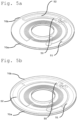
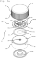
- Figs. 5a and 5b represent a fifth embodiment.
- the closure element 10 of this embodiment is structurally similar to that of the fourth embodiment.
- the relative movement between the first capacitor plates 50, 51 and the second capacitor plate 52 is a rotational movement.
- the second capacitor plate 52 is overlapping both the first capacitor plates 50, 51.
- the second capacitor plate 52 is placed in a different rotational position, not overlapping the first capacitor plates 50, 51.
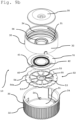
- Figs. 6a to 6d disclose a sixth embodiment.
- the chip and the antenna of the transponder are place on a first support 70a.
- the first support 70a is fixed to the top wall of the inner cap member (not shown), for example by means of an adhesive layer.
- the antenna is arranged in such a way to lie in an O-shaped area.
- first capacitor plates 50, 51 are placed on the first support 70a.
- the first capacitor plates 50, 51 are placed in an inner position with respect to the antenna.
- the first support 70a is a flat element, preferably but not exclusively, round-shaped.
- the second capacitor plate 52 is placed on a second support 70b.
- the second support 70b is fixed to the top wall of the outer cap member (not shown), for example by means of an adhesive layer.
- the second support 70b is a flat element, preferably but not exclusively, round-shaped.
- Each of the first capacitor plates 50, 51 are shaped as a circular sector. Each of the first capacitor plates 50, 51 is arranged so that their centre coincide with a centre of the first support 70a.
- Each of the first capacitor plates 50, 51 defines an angle of 80° to 100°.
- the angle defined by each of the first capacitor plates 50, 51 is 90°.
- the first capacitor plates 50, 51 are places one next to the other in such a way to lie on a semicircle area.
- the second capacitor plate 52 is shaped as a circular second.
- the second capacitor plate 52 is arranged so that its centre coincides with a centre of the second support 70b.
- the second capacitor plate 52 defines an angle of 160° to 200°.
- the angle defined by the second capacitor plate 52 is 180°. Therefore, the second capacitor plate 52 lies on a semicircle area.
- the second capacitor plate 52 is overlapping both the first capacitor plates 50, 51 at a first distance.
- the second capacitor plate 52 in the second (opened) configuration (see Fig. 6d ), the second capacitor plate 52 is still overlapping both the first capacitor plates 50, 51, but at a second distance greater than the first distance.
- the relative movement between the first capacitor plates 50, 51 and the second capacitor plate 52 is a linear movement along the longitudinal direction.
- Figs. 7a and 7b show a seventh embodiment.
- the closure element 10 of this embodiment is structurally similar to that of the sixth embodiment.
- the relative movement between the first capacitor plates 50, 51 and the second capacitor plate 52 is a rotational movement.
- the second capacitor plate 52 is overlapping both the first capacitor plates 50, 51.
- the second capacitor plate 52 is placed in a different angular position, not overlapping the first capacitor plates 50, 51.
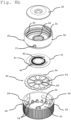
- FIGs. 8a and 8b an eighth embodiment is disclosed.
- the closure element 10 comprises the two first capacitor plates 50, 51 connected to the chip 41 of the transponder 40.
- the chip 41 and the antenna 42 of the transponder 40 and the first capacitor plates 50, 51 are placed on a substrate 70 which is attached to the top wall 31 of the inner cap member 30 by means of an adhesive layer.
- first capacitor plates 50, 51 are arranged on a first surface of the substrate 70 facing the top wall 21 of the outer cap member 20 (see Fig. 8a ).
- the chip 41 and the antenna 42 of the transponder 40 are arranged on a second surface of the substrate 70 facing the top wall 31 of the inner cap member 30 (see Fig. 8b ).
- the first capacitor plates 50, 51 are shaped as curved strips arranged on a peripheral portion of the first surface of the support 70.
- the second capacitor plate 52 comprises a plurality of sections 53 arranged along a circumferential direction.
- the sections 53 are configured to be electrically connected to each other in the first configuration (i.e., closed configuration) and electrically disconnected in second configuration (opened configuration).
- the second capacitor plate 52 comprises a first ring 54 and a second ring 55.
- the first ring 54 has a diameter greater than the diameter of the second ring 55.
- the sections 53 are connected between the first ring 54 and the second ring 55 on the same plane.
- the sections 53 are connected to the first ring 54 and second ring 55 by means of breakable bridges 56.
- the first ring 54 and the second ring 55 are connected to the outer cap member 20.
- sections 53 have the same shape and the same dimension.
- the sections 53 are trapezoidal-shaped and angularly evenly spaced.
- the first ring 54 presents an external edge 54a opposed to an edge connecting the sections 53.
- the external edge 54a is shaped such that the first ring 54 is fastened to the outer cap member 20 in such a way that they rotate together.
- the external edge 54a is indented.
- the indented, external edge 54a of the first ring 54 is housed in a corresponding, counter-shaped indentation 24 (see Fig. 8b ) arranged internally in the outer cap member 20. Therefore, the first ring 54 is fastened to the outer cap member 20.
- An internal edge 55a of the inner ring 55 is opposite to an edge of the inner ring 55 connecting the sections 53.
- the internal edge 55a is shaped such that the second ring 55 is fastened to the outer cap member 20 in such a way that they rotate together.
- the internal edge 55a of the inner ring 55 presents a polygonal shape.
- the internal edge 55a is fitted onto a counter-shaped coupling protuberance 25 projecting from the top wall 21 of the outer cap member 20.
- the sections 53 of the second capacitor plate 52 are fixed to the substrate 70 by means of an adhesive layer.
- This relative rotation determines a breakage of the breakable bridges 56.
- at least part of the sections 53 of the second capacitor plate 52 are electrically disconnected from each other.
- Preferably, all the sections 53 of the second capacitor plate 52 are electrically disconnected from each other.
- the shape of the second capacitor plate 52 changes from a first shape to a second shape, which is different from the first one, when switching from the first configuration to the second configuration. Accordingly, the electrical capacitance of the capacitor defined by the first capacitor plates 50, 51 and the second capacitor plate 52 is modified to detect a change in the configuration of the closure element 10.
- the closure element 10 of the eighth embodiment further comprises the blocking means in line with the other embodiments described above.
- closure element 10 comprises lifting means operatively place between the outer cap member 20 and the inner cap member 30 to lift the outer cap member 20 with reference to the inner cap member 30 when the closure element 1 ⁇ is switched from the first (closed) configuration to the second (opened) configuration.
- the lifting means comprises at least one dog 37 protruding from the side wall 31 of the inner cap member 30.
- the lifting means comprises a plurality of dogs 37.
- the listing means comprises two dogs 37 arranged on opposite positions.
- the dogs 37 slide along corresponding inclined slit 26 on the inner side of side wall 22 of the outer cap member 20. These slits 26 are inclined in a way such that, when the outer cap member 20 is rotated with respect to the inner cap member 30 for opening the closure member, the outer cap member 20 is raised with respect to the inner cap member 30.
- Figs. 9a and 9b show a ninth embodiment of the closure element 10 of the present invention.
- the closure element 10 of the ninth embodiment is similar to that of the eighth embodiment.
- the second capacitor plate 52 is directly connected to both the outer cap member 20 and the inner cap member 30.
- the indented, external edge 54a of the first ring 54 is housed in the corresponding, counter-shaped indentation 24 (see Fig. 9b ) arranged internally in the outer cap member 20. Therefore, the first ring 54 is fastened to the outer cap member 20.
- the internal edge 55a of the inner ring 55 is opposite to an edge of the inner ring 55 connecting the sections 53.
- the internal edge 55a is shaped such that the second ring 55 is fastened to the outer cap member 20 in such a way that they rotate together.
- the internal edge 55a of the inner ring 55 presents a polygonal shape.
- the internal edge 55a is fitted onto a counter-shaped coupling protuberance 38 projecting from a central portion of the top wall 31 of the inner cap member 30.
- the sections 53 of the second capacitor plate 52 are not directly fixed to the substrate 70.
- This relative rotation determines a breakage of the breakable bridges 56.
- at least part of the sections 53 of the second capacitor plate 52 are electrically disconnected from each other.
- Preferably, all the sections 53 of the second capacitor plate 52 are electrically disconnected from each other.
- the shape of the second capacitor plate 52 changes from a first shape to a second shape, which is different from the first one, when switching from the first configuration to the second configuration. Accordingly, the electrical capacitance of the capacitor defined by the first capacitor plates 50, 51 and the second capacitor plate 52 is modified to detect a change in the configuration of the closure element 10.
- Figs. 10a and 10b disclose a tenth embodiment of the closure elements 10 of the present invention.
- the closure element 10 of this embodiment is structurally similar to that of the eighth and ninth embodiments. However, in the tenth embodiment, the connection between the second capacitor plate 52 with the outer cap member 20 and the inner cap member 30 is different.
- the inner cap member 30 comprises a plurality of fixing teeth 39 protruding from the top wall 31.
- the fixing teeth 39 are arranged in such a way that they are at the same distance from each other.
- the indented, external edge 54a of the first ring 54 of the second capacitor plate 52 is fitted with the fixing teeth 39 in such a way that the first ring is fixed to the inner cap member 30.
- the inner cap member 30 further comprises the coupling protrusion 38 protruding from a central portion of the top wall 31.
- the internal edge 55a of the second ring 55 of the second capacitor plate 52 is counter-shaped with the coupling protrusion 38 in such a way that the second ring 55 is fixed to the inner cap member 30.
- Each sector 53 of the second capacitor plate 52 presents a centrally arranged slot 57.
- the outer cap member 20 further comprises a plurality of corresponding fixing protrusions 27 protruding from the top wall 21.
- the fixing protrusions 27 fit into the slots 57 in such a way that the sectors 53 of the second capacitor plate 52 are fixed to the outer cap member 20.
- This relative rotation determines a breakage of the breakable bridges 56.
- at least part of the sections 53 of the second capacitor plate 52 are electrically disconnected from each other.
- Preferably, all the sections 53 of the second capacitor plate 52 are electrically disconnected from each other.
- the shape of the second capacitor plate 52 changes from a first shape to a second shape, which is different from the first one, when switching from the first configuration to the second configuration. Accordingly, the electrical capacitance of the capacitor defined by the first capacitor plates 50, 51 and the second capacitor plate 52 is modified to detect a change in the configuration of the closure element 10.
Landscapes
- Engineering & Computer Science (AREA)
- Mechanical Engineering (AREA)
- Computer Hardware Design (AREA)
- Microelectronics & Electronic Packaging (AREA)
- Physics & Mathematics (AREA)
- General Physics & Mathematics (AREA)
- Theoretical Computer Science (AREA)
- Closures For Containers (AREA)
- Facsimile Transmission Control (AREA)
- Glass Compositions (AREA)
- Tone Control, Compression And Expansion, Limiting Amplitude (AREA)
Priority Applications (1)
| Application Number | Priority Date | Filing Date | Title |
|---|---|---|---|
| PL20714167.2T PL4121901T3 (pl) | 2020-03-20 | 2020-03-20 | Element zamknięciowy |
Applications Claiming Priority (1)
| Application Number | Priority Date | Filing Date | Title |
|---|---|---|---|
| PCT/EP2020/057819 WO2021185456A1 (en) | 2020-03-20 | 2020-03-20 | Closure element |
Publications (2)
| Publication Number | Publication Date |
|---|---|
| EP4121901A1 EP4121901A1 (en) | 2023-01-25 |
| EP4121901B1 true EP4121901B1 (en) | 2024-09-11 |
Family
ID=70005617
Family Applications (1)
| Application Number | Title | Priority Date | Filing Date |
|---|---|---|---|
| EP20714167.2A Active EP4121901B1 (en) | 2020-03-20 | 2020-03-20 | Closure element |
Country Status (10)
| Country | Link |
|---|---|
| US (1) | US12091227B2 (pl) |
| EP (1) | EP4121901B1 (pl) |
| CN (1) | CN115989501B (pl) |
| AR (1) | AR121603A1 (pl) |
| AU (1) | AU2020436183A1 (pl) |
| CO (1) | CO2022014422A2 (pl) |
| ES (1) | ES2999018T3 (pl) |
| MX (1) | MX2022011663A (pl) |
| PL (1) | PL4121901T3 (pl) |
| WO (1) | WO2021185456A1 (pl) |
Families Citing this family (2)
| Publication number | Priority date | Publication date | Assignee | Title |
|---|---|---|---|---|
| US11893437B2 (en) * | 2017-07-21 | 2024-02-06 | Avery Dennison Retail Information Services Llc | RFID vial tracking with RFID inlay |
| CN115989501B (zh) | 2020-03-20 | 2025-08-29 | 刮拉瓶盖股份公司 | 封口元件 |
Family Cites Families (18)
| Publication number | Priority date | Publication date | Assignee | Title |
|---|---|---|---|---|
| EP1665135B1 (en) | 2003-09-08 | 2016-08-17 | Frances M. Claessens | Bottle cap |
| US20070273532A1 (en) | 2006-05-17 | 2007-11-29 | Tagsys Sas | RFID tag for conductive surface |
| US7705734B2 (en) | 2006-12-21 | 2010-04-27 | Martinelli Lawrence G | Secure product packaging |
| US20080238675A1 (en) | 2007-04-02 | 2008-10-02 | Gigatek Inc. | Rfid tag system |
| US20080314900A1 (en) * | 2007-06-14 | 2008-12-25 | Drug Plastics & Glass Company, Inc. | Enclosure having an automatic identification device |
| JP2009001326A (ja) | 2007-06-25 | 2009-01-08 | Nec Corp | キャップ |
| KR100967340B1 (ko) | 2009-05-19 | 2010-07-05 | (주)이그잭스 | 알에프아이디 칩 파기형 병입상품 위조방지 장치 |
| WO2013167701A1 (de) | 2012-05-09 | 2013-11-14 | Schreiner Group Gmbh & Co. Kg | Verschlusselement für ein gefäss |
| WO2014002971A1 (ja) | 2012-06-25 | 2014-01-03 | 東洋製罐グループホールディングス株式会社 | Icタグ付複合容器蓋 |
| TWI546836B (zh) * | 2014-10-28 | 2016-08-21 | 鈺邦科技股份有限公司 | 封口元件及其捲繞型固態電解電容器 |
| US9542637B2 (en) | 2014-12-31 | 2017-01-10 | Intermec, Inc. | RFID tag with anti-tamper assembly |
| DE102015001825A1 (de) | 2015-02-16 | 2016-08-18 | Thyssenkrupp Ag | Förderanlage für den offenen Tagebau |
| FR3037570B1 (fr) | 2015-06-22 | 2018-06-29 | Pernod Ricard | Bouteille comportant un bouchage de securite |
| CN106628581B (zh) | 2015-10-30 | 2019-08-02 | 四川谦泰仁投资管理有限公司 | 一种带状态触点的rfid标签的组合瓶盖 |
| FR3050189B1 (fr) | 2016-04-15 | 2020-05-08 | Commissariat A L'energie Atomique Et Aux Energies Alternatives | Dispositif de securisation destine a securiser un recipient |
| EP3260390B1 (en) * | 2016-06-22 | 2019-12-04 | Clariant Healthcare Packaging (France) SAS | Outer cap for a child-resistant closure, child-resistant closure, container with such closure and its use |
| AU2020437021A1 (en) | 2020-03-20 | 2022-10-13 | Guala Closures S.P.A. | Closure element |
| CN115989501B (zh) | 2020-03-20 | 2025-08-29 | 刮拉瓶盖股份公司 | 封口元件 |
-
2020
- 2020-03-20 CN CN202080101139.9A patent/CN115989501B/zh active Active
- 2020-03-20 WO PCT/EP2020/057819 patent/WO2021185456A1/en not_active Ceased
- 2020-03-20 MX MX2022011663A patent/MX2022011663A/es unknown
- 2020-03-20 EP EP20714167.2A patent/EP4121901B1/en active Active
- 2020-03-20 AU AU2020436183A patent/AU2020436183A1/en active Pending
- 2020-03-20 US US17/913,109 patent/US12091227B2/en active Active
- 2020-03-20 ES ES20714167T patent/ES2999018T3/es active Active
- 2020-03-20 PL PL20714167.2T patent/PL4121901T3/pl unknown
-
2021
- 2021-03-18 AR ARP210100674A patent/AR121603A1/es active IP Right Grant
-
2022
- 2022-10-11 CO CONC2022/0014422A patent/CO2022014422A2/es unknown
Also Published As
| Publication number | Publication date |
|---|---|
| AR121603A1 (es) | 2022-06-22 |
| US12091227B2 (en) | 2024-09-17 |
| CN115989501A (zh) | 2023-04-18 |
| AU2020436183A1 (en) | 2022-10-20 |
| EP4121901A1 (en) | 2023-01-25 |
| WO2021185456A1 (en) | 2021-09-23 |
| MX2022011663A (es) | 2023-01-04 |
| CN115989501B (zh) | 2025-08-29 |
| US20230126968A1 (en) | 2023-04-27 |
| CO2022014422A2 (es) | 2023-03-17 |
| PL4121901T3 (pl) | 2025-03-10 |
| ES2999018T3 (en) | 2025-02-24 |
Similar Documents
| Publication | Publication Date | Title |
|---|---|---|
| EP4121901B1 (en) | Closure element | |
| EP1665135B1 (en) | Bottle cap | |
| US9975669B2 (en) | Hinged closure device with first opening indicator | |
| CN102056815A (zh) | 设置有ic标签的树脂顶盖 | |
| US7342501B2 (en) | Closure and package with induction seal and RFID tag | |
| EP1984271B1 (en) | Closure and package with induction seal and rfid tag | |
| US7772981B1 (en) | Non-removable closure with integral RFID | |
| RU2701589C2 (ru) | Укупорочное средство с индикацией несанкционированного вскрытия | |
| EP3655892A1 (en) | Rfid vial tracking with rfid inlay | |
| CN115943385B (zh) | 封闭元件 | |
| EP3698279A1 (en) | Closure member | |
| US10565411B2 (en) | Detection of seal integrity on products using RFID | |
| JP6109566B2 (ja) | Icタグを備えて成る複合容器蓋及び包装容器 | |
| RU2811531C1 (ru) | Закрывающий элемент | |
| EP2183168B1 (en) | Vessel | |
| JP5950719B2 (ja) | Icタグを備えて成る複合容器蓋及び包装容器 | |
| JP6096554B2 (ja) | Icタグを備えて成る複合容器蓋 | |
| RU2811972C1 (ru) | Закрывающий элемент | |
| KR20100125999A (ko) | 위조 방지용 안전 캡 및 이를 포함하는 위조 방지 용기 |
Legal Events
| Date | Code | Title | Description |
|---|---|---|---|
| STAA | Information on the status of an ep patent application or granted ep patent |
Free format text: STATUS: UNKNOWN |
|
| STAA | Information on the status of an ep patent application or granted ep patent |
Free format text: STATUS: THE INTERNATIONAL PUBLICATION HAS BEEN MADE |
|
| PUAI | Public reference made under article 153(3) epc to a published international application that has entered the european phase |
Free format text: ORIGINAL CODE: 0009012 |
|
| STAA | Information on the status of an ep patent application or granted ep patent |
Free format text: STATUS: REQUEST FOR EXAMINATION WAS MADE |
|
| 17P | Request for examination filed |
Effective date: 20220922 |
|
| AK | Designated contracting states |
Kind code of ref document: A1 Designated state(s): AL AT BE BG CH CY CZ DE DK EE ES FI FR GB GR HR HU IE IS IT LI LT LU LV MC MK MT NL NO PL PT RO RS SE SI SK SM TR |
|
| P01 | Opt-out of the competence of the unified patent court (upc) registered |
Effective date: 20230512 |
|
| DAV | Request for validation of the european patent (deleted) | ||
| DAX | Request for extension of the european patent (deleted) | ||
| GRAP | Despatch of communication of intention to grant a patent |
Free format text: ORIGINAL CODE: EPIDOSNIGR1 |
|
| STAA | Information on the status of an ep patent application or granted ep patent |
Free format text: STATUS: GRANT OF PATENT IS INTENDED |
|
| INTG | Intention to grant announced |
Effective date: 20240409 |
|
| GRAS | Grant fee paid |
Free format text: ORIGINAL CODE: EPIDOSNIGR3 |
|
| GRAA | (expected) grant |
Free format text: ORIGINAL CODE: 0009210 |
|
| STAA | Information on the status of an ep patent application or granted ep patent |
Free format text: STATUS: THE PATENT HAS BEEN GRANTED |
|
| AK | Designated contracting states |
Kind code of ref document: B1 Designated state(s): AL AT BE BG CH CY CZ DE DK EE ES FI FR GB GR HR HU IE IS IT LI LT LU LV MC MK MT NL NO PL PT RO RS SE SI SK SM TR |
|
| REG | Reference to a national code |
Ref country code: GB Ref legal event code: FG4D |
|
| REG | Reference to a national code |
Ref country code: CH Ref legal event code: EP |
|
| REG | Reference to a national code |
Ref country code: DE Ref legal event code: R096 Ref document number: 602020037502 Country of ref document: DE |
|
| REG | Reference to a national code |
Ref country code: IE Ref legal event code: FG4D |
|
| REG | Reference to a national code |
Ref country code: SE Ref legal event code: TRGR |
|
| REG | Reference to a national code |
Ref country code: LT Ref legal event code: MG9D |
|
| PG25 | Lapsed in a contracting state [announced via postgrant information from national office to epo] |
Ref country code: NO Free format text: LAPSE BECAUSE OF FAILURE TO SUBMIT A TRANSLATION OF THE DESCRIPTION OR TO PAY THE FEE WITHIN THE PRESCRIBED TIME-LIMIT Effective date: 20241211 |
|
| REG | Reference to a national code |
Ref country code: NL Ref legal event code: MP Effective date: 20240911 |
|
| PG25 | Lapsed in a contracting state [announced via postgrant information from national office to epo] |
Ref country code: GR Free format text: LAPSE BECAUSE OF FAILURE TO SUBMIT A TRANSLATION OF THE DESCRIPTION OR TO PAY THE FEE WITHIN THE PRESCRIBED TIME-LIMIT Effective date: 20241212 Ref country code: FI Free format text: LAPSE BECAUSE OF FAILURE TO SUBMIT A TRANSLATION OF THE DESCRIPTION OR TO PAY THE FEE WITHIN THE PRESCRIBED TIME-LIMIT Effective date: 20240911 |
|
| PG25 | Lapsed in a contracting state [announced via postgrant information from national office to epo] |
Ref country code: LV Free format text: LAPSE BECAUSE OF FAILURE TO SUBMIT A TRANSLATION OF THE DESCRIPTION OR TO PAY THE FEE WITHIN THE PRESCRIBED TIME-LIMIT Effective date: 20240911 |
|
| PG25 | Lapsed in a contracting state [announced via postgrant information from national office to epo] |
Ref country code: HR Free format text: LAPSE BECAUSE OF FAILURE TO SUBMIT A TRANSLATION OF THE DESCRIPTION OR TO PAY THE FEE WITHIN THE PRESCRIBED TIME-LIMIT Effective date: 20240911 |
|
| PG25 | Lapsed in a contracting state [announced via postgrant information from national office to epo] |
Ref country code: RS Free format text: LAPSE BECAUSE OF FAILURE TO SUBMIT A TRANSLATION OF THE DESCRIPTION OR TO PAY THE FEE WITHIN THE PRESCRIBED TIME-LIMIT Effective date: 20241211 |
|
| PG25 | Lapsed in a contracting state [announced via postgrant information from national office to epo] |
Ref country code: RS Free format text: LAPSE BECAUSE OF FAILURE TO SUBMIT A TRANSLATION OF THE DESCRIPTION OR TO PAY THE FEE WITHIN THE PRESCRIBED TIME-LIMIT Effective date: 20241211 Ref country code: NO Free format text: LAPSE BECAUSE OF FAILURE TO SUBMIT A TRANSLATION OF THE DESCRIPTION OR TO PAY THE FEE WITHIN THE PRESCRIBED TIME-LIMIT Effective date: 20241211 Ref country code: LV Free format text: LAPSE BECAUSE OF FAILURE TO SUBMIT A TRANSLATION OF THE DESCRIPTION OR TO PAY THE FEE WITHIN THE PRESCRIBED TIME-LIMIT Effective date: 20240911 Ref country code: HR Free format text: LAPSE BECAUSE OF FAILURE TO SUBMIT A TRANSLATION OF THE DESCRIPTION OR TO PAY THE FEE WITHIN THE PRESCRIBED TIME-LIMIT Effective date: 20240911 Ref country code: GR Free format text: LAPSE BECAUSE OF FAILURE TO SUBMIT A TRANSLATION OF THE DESCRIPTION OR TO PAY THE FEE WITHIN THE PRESCRIBED TIME-LIMIT Effective date: 20241212 Ref country code: FI Free format text: LAPSE BECAUSE OF FAILURE TO SUBMIT A TRANSLATION OF THE DESCRIPTION OR TO PAY THE FEE WITHIN THE PRESCRIBED TIME-LIMIT Effective date: 20240911 |
|
| REG | Reference to a national code |
Ref country code: AT Ref legal event code: MK05 Ref document number: 1723341 Country of ref document: AT Kind code of ref document: T Effective date: 20240911 |
|
| PG25 | Lapsed in a contracting state [announced via postgrant information from national office to epo] |
Ref country code: NL Free format text: LAPSE BECAUSE OF FAILURE TO SUBMIT A TRANSLATION OF THE DESCRIPTION OR TO PAY THE FEE WITHIN THE PRESCRIBED TIME-LIMIT Effective date: 20240911 |
|
| REG | Reference to a national code |
Ref country code: ES Ref legal event code: FG2A Ref document number: 2999018 Country of ref document: ES Kind code of ref document: T3 Effective date: 20250224 |
|
| PGFP | Annual fee paid to national office [announced via postgrant information from national office to epo] |
Ref country code: SE Payment date: 20250321 Year of fee payment: 6 |
|
| PG25 | Lapsed in a contracting state [announced via postgrant information from national office to epo] |
Ref country code: IS Free format text: LAPSE BECAUSE OF FAILURE TO SUBMIT A TRANSLATION OF THE DESCRIPTION OR TO PAY THE FEE WITHIN THE PRESCRIBED TIME-LIMIT Effective date: 20250111 Ref country code: PT Free format text: LAPSE BECAUSE OF FAILURE TO SUBMIT A TRANSLATION OF THE DESCRIPTION OR TO PAY THE FEE WITHIN THE PRESCRIBED TIME-LIMIT Effective date: 20250113 |
|
| PGFP | Annual fee paid to national office [announced via postgrant information from national office to epo] |
Ref country code: DE Payment date: 20250319 Year of fee payment: 6 |
|
| PG25 | Lapsed in a contracting state [announced via postgrant information from national office to epo] |
Ref country code: RO Free format text: LAPSE BECAUSE OF FAILURE TO SUBMIT A TRANSLATION OF THE DESCRIPTION OR TO PAY THE FEE WITHIN THE PRESCRIBED TIME-LIMIT Effective date: 20240911 Ref country code: SM Free format text: LAPSE BECAUSE OF FAILURE TO SUBMIT A TRANSLATION OF THE DESCRIPTION OR TO PAY THE FEE WITHIN THE PRESCRIBED TIME-LIMIT Effective date: 20240911 |
|
| PGFP | Annual fee paid to national office [announced via postgrant information from national office to epo] |
Ref country code: BG Payment date: 20250321 Year of fee payment: 6 |
|
| PG25 | Lapsed in a contracting state [announced via postgrant information from national office to epo] |
Ref country code: EE Free format text: LAPSE BECAUSE OF FAILURE TO SUBMIT A TRANSLATION OF THE DESCRIPTION OR TO PAY THE FEE WITHIN THE PRESCRIBED TIME-LIMIT Effective date: 20240911 Ref country code: AT Free format text: LAPSE BECAUSE OF FAILURE TO SUBMIT A TRANSLATION OF THE DESCRIPTION OR TO PAY THE FEE WITHIN THE PRESCRIBED TIME-LIMIT Effective date: 20240911 |
|
| PG25 | Lapsed in a contracting state [announced via postgrant information from national office to epo] |
Ref country code: CZ Free format text: LAPSE BECAUSE OF FAILURE TO SUBMIT A TRANSLATION OF THE DESCRIPTION OR TO PAY THE FEE WITHIN THE PRESCRIBED TIME-LIMIT Effective date: 20240911 |
|
| PGFP | Annual fee paid to national office [announced via postgrant information from national office to epo] |
Ref country code: FR Payment date: 20250326 Year of fee payment: 6 Ref country code: PL Payment date: 20250312 Year of fee payment: 6 |
|
| PG25 | Lapsed in a contracting state [announced via postgrant information from national office to epo] |
Ref country code: SK Free format text: LAPSE BECAUSE OF FAILURE TO SUBMIT A TRANSLATION OF THE DESCRIPTION OR TO PAY THE FEE WITHIN THE PRESCRIBED TIME-LIMIT Effective date: 20240911 |
|
| PGFP | Annual fee paid to national office [announced via postgrant information from national office to epo] |
Ref country code: IT Payment date: 20250324 Year of fee payment: 6 Ref country code: GB Payment date: 20250326 Year of fee payment: 6 |
|
| REG | Reference to a national code |
Ref country code: DE Ref legal event code: R097 Ref document number: 602020037502 Country of ref document: DE |
|
| PG25 | Lapsed in a contracting state [announced via postgrant information from national office to epo] |
Ref country code: DK Free format text: LAPSE BECAUSE OF FAILURE TO SUBMIT A TRANSLATION OF THE DESCRIPTION OR TO PAY THE FEE WITHIN THE PRESCRIBED TIME-LIMIT Effective date: 20240911 |
|
| PGFP | Annual fee paid to national office [announced via postgrant information from national office to epo] |
Ref country code: ES Payment date: 20250429 Year of fee payment: 6 |
|
| PLBE | No opposition filed within time limit |
Free format text: ORIGINAL CODE: 0009261 |
|
| STAA | Information on the status of an ep patent application or granted ep patent |
Free format text: STATUS: NO OPPOSITION FILED WITHIN TIME LIMIT |
|
| 26N | No opposition filed |
Effective date: 20250612 |
|
| PG25 | Lapsed in a contracting state [announced via postgrant information from national office to epo] |
Ref country code: MC Free format text: LAPSE BECAUSE OF FAILURE TO SUBMIT A TRANSLATION OF THE DESCRIPTION OR TO PAY THE FEE WITHIN THE PRESCRIBED TIME-LIMIT Effective date: 20240911 |
|
| REG | Reference to a national code |
Ref country code: CH Ref legal event code: H13 Free format text: ST27 STATUS EVENT CODE: U-0-0-H10-H13 (AS PROVIDED BY THE NATIONAL OFFICE) Effective date: 20251023 |
|
| PG25 | Lapsed in a contracting state [announced via postgrant information from national office to epo] |
Ref country code: LU Free format text: LAPSE BECAUSE OF NON-PAYMENT OF DUE FEES Effective date: 20250320 |