EP4121685B1 - Batteriebetriebene fettpresse - Google Patents
Batteriebetriebene fettpresse Download PDFInfo
- Publication number
- EP4121685B1 EP4121685B1 EP21769884.4A EP21769884A EP4121685B1 EP 4121685 B1 EP4121685 B1 EP 4121685B1 EP 21769884 A EP21769884 A EP 21769884A EP 4121685 B1 EP4121685 B1 EP 4121685B1
- Authority
- EP
- European Patent Office
- Prior art keywords
- channel
- grease
- chamber
- spool
- pressure
- Prior art date
- Legal status (The legal status is an assumption and is not a legal conclusion. Google has not performed a legal analysis and makes no representation as to the accuracy of the status listed.)
- Active
Links
Images









Classifications
-
- F—MECHANICAL ENGINEERING; LIGHTING; HEATING; WEAPONS; BLASTING
- F16—ENGINEERING ELEMENTS AND UNITS; GENERAL MEASURES FOR PRODUCING AND MAINTAINING EFFECTIVE FUNCTIONING OF MACHINES OR INSTALLATIONS; THERMAL INSULATION IN GENERAL
- F16N—LUBRICATING
- F16N13/00—Lubricating-pumps
- F16N13/02—Lubricating-pumps with reciprocating piston
- F16N13/06—Actuation of lubricating-pumps
-
- F—MECHANICAL ENGINEERING; LIGHTING; HEATING; WEAPONS; BLASTING
- F16—ENGINEERING ELEMENTS AND UNITS; GENERAL MEASURES FOR PRODUCING AND MAINTAINING EFFECTIVE FUNCTIONING OF MACHINES OR INSTALLATIONS; THERMAL INSULATION IN GENERAL
- F16N—LUBRICATING
- F16N13/00—Lubricating-pumps
- F16N13/02—Lubricating-pumps with reciprocating piston
- F16N13/06—Actuation of lubricating-pumps
- F16N13/10—Actuation of lubricating-pumps with mechanical drive
- F16N13/14—Actuation of lubricating-pumps with mechanical drive with cam or wobble-plate on shaft parallel to the pump cylinder or cylinders
-
- F—MECHANICAL ENGINEERING; LIGHTING; HEATING; WEAPONS; BLASTING
- F16—ENGINEERING ELEMENTS AND UNITS; GENERAL MEASURES FOR PRODUCING AND MAINTAINING EFFECTIVE FUNCTIONING OF MACHINES OR INSTALLATIONS; THERMAL INSULATION IN GENERAL
- F16N—LUBRICATING
- F16N3/00—Devices for supplying lubricant by manual action
- F16N3/10—Devices for supplying lubricant by manual action delivering grease
- F16N3/12—Grease guns
-
- F—MECHANICAL ENGINEERING; LIGHTING; HEATING; WEAPONS; BLASTING
- F16—ENGINEERING ELEMENTS AND UNITS; GENERAL MEASURES FOR PRODUCING AND MAINTAINING EFFECTIVE FUNCTIONING OF MACHINES OR INSTALLATIONS; THERMAL INSULATION IN GENERAL
- F16N—LUBRICATING
- F16N13/00—Lubricating-pumps
- F16N13/02—Lubricating-pumps with reciprocating piston
- F16N13/06—Actuation of lubricating-pumps
- F16N2013/063—Actuation of lubricating-pumps with electrical drive
-
- F—MECHANICAL ENGINEERING; LIGHTING; HEATING; WEAPONS; BLASTING
- F16—ENGINEERING ELEMENTS AND UNITS; GENERAL MEASURES FOR PRODUCING AND MAINTAINING EFFECTIVE FUNCTIONING OF MACHINES OR INSTALLATIONS; THERMAL INSULATION IN GENERAL
- F16N—LUBRICATING
- F16N2280/00—Valves
Definitions
- the disclosure relates to a grease gun, and in particular a battery operated grease gun.
- Grease guns are used in a range of industries to lubricate vehicles and other machinery. These grease guns generally include a grease supply (either from an attached barrel or an external source) and a piston, which forces grease under pressure out of an outlet, for application to the relevant machinery. Grease guns can be separated into two main types; manual grease guns and power-assisted grease guns (which includes battery-operated, pneumatic and electric grease guns).
- US 2009/272762 A1 discloses a two stage grease gun with an actuation handle for delivery of grease in a high volume/low pressure manner and automatically shifting to a high pressure/low volume manner when higher pressures are needed such as to overcome clogging.
- a check valve is provided which automatically closes when pressure required to inject grease exceeds a threshold value.
- US 2008/047980 A1 discloses a grease output device for an electrical grease gun. By reciprocating movement of two pistol rods alternatively, grease can flow out successively and quickly to enhance lifespan and generate high efficiency.
- a battery operated grease gun comprising a body able to be connected to a container configured to store grease, the body defining first and second elongate chambers therein, the first chamber extending along a first axis and the second chamber extending along a second axis, the first axis being spaced from the second axis; first and second pistons, the first piston configured to reciprocate within the first chamber along the first axis and the second piston configured to reciprocate within the second chamber along the second axis; a common grease channel, the common grease channel being disposed between the container and the first and second chambers such that the grease is able to flow from the container into the first and second chambers; an actuator connected to the body and moveable between a retracted position, whereby grease is able to flow through the common grease channel, and an engaged position, whereby grease is restricted from flowing through the common grease channel, the actuator being configured to cause reciprocation of the first piston and the second piston when moved between the engaged and retracted positions;
- the grease outlet is fluidically connected to the first chamber and the second chamber by way of a third chamber connected to the first chamber and a fourth chamber connected to the second chamber.
- the first chamber is connected to the third chamber by way of a first grease channel.
- the grease gun further comprises a first non-return valve located within the first grease channel.
- the first non-return valve allows grease to flow from the first chamber through the first grease channel into the third chamber.
- the first non-return valve restricts grease from flowing from the third chamber into the first chamber. More preferably, the first non-return valve prevents grease from flowing from the third chamber into the first chamber.
- the second chamber is connected to the fourth chamber by way of a second grease channel.
- the grease gun further comprises a second non-return valve located within the second grease channel.
- the second non-return valve allows grease to flow from the second chamber through the second grease channel into the fourth chamber.
- the second non-return valve restricts grease from flowing from the fourth chamber into the second chamber. More preferably, the second non-return valve prevents grease from flowing from the fourth chamber into the second chamber.
- the grease gun further comprises an outlet cavity between the third chamber and the fourth chamber and the grease outlet.
- the grease gun further comprises the container, which is connected to the body and in fluid communication with the common grease channel.
- the actuator is configured to cause reciprocation of the first and second pistons in the same phase when moved between the engaged and retracted positions.
- the grease gun further comprises a link connected to the first and second pistons to maintain the first and second pistons in the same phase.
- the actuator is connected to the body for rotational movement around a central axis which is perpendicular to the first axis.
- the actuator further comprises a cam member.
- the link contains an aperture with a cam surface that is engageable with the cam member such that the rotational movement of the actuator causes reciprocation of the link.
- the actuator is operable by way of a motor.
- the motor is battery powered.
- the outlet comprises a nozzle.
- the nozzle has a central axis, and the central axis of the nozzle is perpendicular to the first and second axes.
- a grease gun further comprising a spool channel extending along a third axis, a spool moveable within the spool channel between an open position and a closed position; and a bypass channel in fluid communication with the first chamber and the container by way of the spool channel; wherein when the spool is in the open position, it permits the flow of grease out of the first chamber to the container, and when the spool is in the closed position, it restricts the flow of grease out of the first chamber to the container.
- the spool in use, when the spool is in the open position, it permits the flow of grease out of the first chamber into the container and when the spool is in the closed position, it restricts the flow of grease out of the first chamber into the container. Preferably, when the spool is in the closed position, it prevents the flow of grease out of the first chamber into the container.
- a grease gun further comprising a pressure channel disposed at a first end of the spool channel, the pressure channel being in fluid communication with the outlet chamber; and a third biasing means disposed at a second end of the spool channel, the third biasing means being configured to bias the spool towards the closed position, wherein an increase in pressure in the outlet chamber causes an increase in pressure in the pressure channel and a resulting increase in pressure at the first end of the spool channel to thereby force the spool against the third biasing means.
- the spool is configured to move towards the open position.
- the bypass channel comprises a primary bypass channel disposed between the first chamber and the spool channel, and a secondary bypass channel disposed between the spool channel and the container.
- the primary bypass channel extends along a primary bypass channel axis and the secondary bypass channel extends along a secondary bypass channel axis, the primary bypass channel axis being offset from the secondary bypass channel axis with regard to the spool channel.
- the primary bypass channel axis is substantially perpendicular to, and spaced from, the secondary bypass channel axis.
- the spool channel is connected to and disposed between the primary and secondary bypass channels such that when the spool is in the open position grease is able to flow from the primary bypass channel into the secondary bypass channel via the spool channel.
- the spool comprises a first annular ring and a second annular ring that is spaced from the first annular ring; and a mid-section that is disposed between and boundaried by the first and second annular rings; the mid-section of the spool having a smaller diameter than a diameter of the spool channel and a diameter of the first and second annular rings; wherein an area disposed between the mid-section of the spool and a wall of the spool channel forms a communication channel, the communication channel being in fluid communication with the primary bypass channel regardless of whether the spool is in the open position or the closed position.
- the spool comprises a cavity that extends through the spool, the cavity being disposed in the mid-section of the spool to allow grease to flow through the mid-section of the spool and fill the communication channel.
- the communication channel when the spool is in the closed position, the communication channel is not located adjacent to the secondary bypass channel, thereby restricting the flow of grease from the spool channel into the secondary bypass channel and when the spool is in the open position, the communication channel is located adjacent to the secondary bypass channel, thereby permitting the flow of grease into the secondary bypass channel.
- a grease gun further comprising a first bypass valve, the first bypass valve being disposed within the first grease channel and having an open configuration and a closed configuration, wherein the first bypass valve is in the open configuration grease is able to flow from the first chamber into the third chamber and when the first bypass valve is in the closed configuration grease is restricted from flowing from the first chamber into the third chamber; wherein the first bypass valve is configured to be in the closed configuration when the pressure in the first chamber is less than the pressure in the third chamber and configured to be in the open configuration when the pressure in the first chamber is greater than the pressure in the third chamber.
- a grease gun wherein the first chamber has a first diameter, and the first piston has a second diameter, wherein the second diameter is smaller than the first diameter such that a radial gap is formed between the first chamber and the first piston, wherein when the pressure in the first chamber reaches a predetermined level, upon reciprocation of the first piston from the retracted position to the engaged position, grease is forced along the radial gap in the first chamber into the common grease channel.
- the second chamber has a third diameter
- the second piston has a fourth diameter, wherein the third diameter and the fourth diameter are sized such that grease is restricted from flowing between the second chamber and the second piston into the common grease channel.
- a grease gun further comprising engagement means on the body of the grease gun for attachment to corresponding engagement means on the container.
- the engagement means comprise an outer collar and an inner collar, wherein the outer collar is axially movable on the inner collar between a locked position where the inner collar can secure the container to the body of the grease gun and an unlocked position where the container can be released from the body.
- the inner collar comprises a collar ball channel containing collar locking balls, which are engageable with a corresponding groove on the container.
- the locked position the container is held to the body by the engagement of the collar locking balls of the collar ball channel with the corresponding groove on the container.
- the collar locking balls have an engaged position within the collar ball channel where they are engageable with the corresponding groove on the container, and a disengaged position within the collar ball channel where they are not engageable with the corresponding groove on the container.
- the collar locking balls are in the engaged position when the outer collar is located on the inner collar in a position adjacent to the collar ball groove and are in the disengaged position when the outer collar is located on the inner collar in a position not adjacent to the collar ball groove.
- the outer collar further comprises a tab.
- the outer collar is movable between the locked position and the unlocked position by rotation of the tab.
- the grease gun may further comprise; a first magnet mounted to the first monitoring spool; and a proximity sensor disposed adjacent the magnet, the proximity sensor being configured to generate a signal that is indicative of the position of the magnet.
- the grease gun may further comprise; a second pressure relief channel that fluidically connects the outlet to the container; and a second pressure relief valve disposed within the second pressure relief channel, the second pressure relief valve being configured to open and thereby allow grease to flow from the outlet to the container when the pressure in the outlet is at or above a predetermined pressure.
- the grease gun may further comprise; a second monitoring channel spaced from the second pressure relief channel; a second connecting channel that fluidically connects the second monitoring channel to the second pressure relief channel; and a second monitoring spool disposed within the second monitoring channel, the second monitoring spool being configured to translate within the second monitoring channel along a longitudinal axis of the second monitoring channel between a closed and open position, wherein when the second monitoring spool is in the open position, grease is able to flow from the outlet to the container via the second connecting channel.
- the grease gun may further comprise; a second magnet mounted to the second monitoring spool; and a second proximity sensor disposed adjacent the second magnet, the second proximity sensor being configured to generate a signal that is indicative of the position of the second magnet.
- the grease gun may comprise a controller configured to receive the signals generated by the first and second proximity sensors, the controller being configured to determine information about the grease gun in dependence on the signals generated by the first and second proximity sensors; and an LCD configured to display the determined information.
- the controller may be configured to receive the signal of the one hydraulic switch and determine information about the grease gun in dependence on that signal.
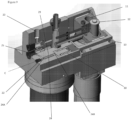
- a grease gun will now be described with reference to a Figures 1 to 30 .
- the grease gun 1 includes an actuator, in the form of a crank wheel 2, and a body 3.
- body 3 is connected to a container, in the form of a grease barrel 4.
- the grease barrel 4 is designed for filling through standard grease cartridges or bulk filled from a grease source.
- grease barrel 4 When grease barrel 4 is empty, if using grease cartridges, grease barrel 4 will be uncoupled from body 3 to access and replace the cartridge; if bulk filled instead, when grease barrel 4 is empty, it can be connected to a grease source through filler/bleeder 5 for refilling (see, for example, Figs. 2 and 4 ).
- the body 3 includes a first elongate chamber 6 (as shown in Fig. 2 ) and second elongate chamber 7 (as shown in Fig. 3 ).
- Second chamber 7 has a smaller cross-sectional area relative to the cross-sectional area of the first chamber 6 and therefore is configured to hold a smaller volume of grease than first chamber 6.
- first chamber 6 and second chamber 7 are circular in cross-section and second chamber 7 is of a smaller diameter to the diameter of the first chamber 6.
- First chamber 6 extends along a first axis A and second chamber 7 extends along a second axis B, the axes being spaced apart.
- first axis A and second axis B are substantially parallel to one another.
- First piston 8 is moveable within first chamber 6 such that it moves (e.g. translates, reciprocates) along first axis A.
- Second piston 9 is moveable within second chamber 7 such that it moves (e.g. translates, reciprocates) along second axis B.
- the pistons are still able to be actuated in the same phase by crank wheel 2, in an alternate embodiment (not shown) the axes A and B may not be parallel to one another.
- First piston 8 and second piston 9 may be located on the same horizontal plane in a side-by-side configuration, as shown in Figs. 4 and 5 , or may be located on the same vertical plane in a top-bottom configuration, as shown in Figs. 6 to 8 .
- These configurations provide different advantages for the operation of the system.
- the side-by-side configuration shown in Figs. 4 and 5 provides more compactness and cost-effectiveness to the design in terms of allowing a smaller gun body.
- the top-bottom configuration shown in Figs. 6 to 8 provides, for example, more balance to side-loads on the crank and pistons thereby ensuring better longevity of the mechanism.
- First piston 8 and second piston 9 are fixed at one end to link 10.
- the fixing of first piston 8 and second piston 9 to link 10 holds the pistons in a fixed relationship with respect to one another so that they reciprocate in the same phase.
- first piston 8 and second piston 9 are fixed in a side-by-side configuration on link 10.
- first piston 8 is fixed to link 10 below second piston 9.
- Side guides 47 are arranged on both sides of the link to take side loads and enable the link to discharge purely axial loads on the two pistons. In the detailed embodiment, side guides 47 are made of high wear resistance material.
- Link 10 contains an aperture 11.
- Cam 12 is attached to crank wheel 2.
- cam 12 is caused to rotate in a circular movement along the edge of crank wheel 2.
- Cam 12 is received within aperture 11.
- cam 12 travels within aperture 11 in a direction substantially perpendicular to first axis A.
- first piston 8 and second piston 9 are continually reciprocated by crank wheel 2 from a fully engaged position (as shown in, for example, Fig. 6 ) to a fully retracted position (as shown in, for example, Fig.
- the engaged, or extended, position of the crank wheel 2 corresponds with an extended position for the first and second pistons.
- the retracted, or disengaged, position of the crank wheel 2 corresponds with a retracted position for the first and second pistons.
- the partially engaged, or partially extended, position of the crank wheel 2 corresponds with a partially extended position for the first and second pistons (e.g. the pistons are part way through a translation in one direction or the other).
- crank wheel 2 The movement of crank wheel 2 is driven by motor 37.
- Motor 37 could be, for example an electric 18VDC motor, a 12VDC motor, a 21VDC motor or a 24 VDC motor. As will be apparent to the skilled addressee, other motors may be suitable.
- Motor 37 is powered by battery 38.
- the battery may be, for example, a lithium-ion battery, a nickel-metal hydride battery or a nickel-cadmium battery. Preferably, the battery is rechargeable. As will be apparent to the skilled addressee, other batteries may be suitable.
- First chamber 6 and second chamber 7 are fluidically connected with each other, and with grease barrel 4 via common grease channel 13.
- first piston 8 and second piston 9 When first piston 8 and second piston 9 are in the retracted position, they are located in such a position within first chamber 6 and second chamber 7, respectively, that they do not block the flow of grease from grease barrel 4 into first chamber 6 and second chamber 7 via common grease channel 13.
- first piston 8 and second piston 9 As first piston 8 and second piston 9 move from the retracted position to the intermediate position, they advance within first chamber 6 along first axis A and within second chamber 7 along second axis B, respectively, progressively obstructing and eventually closing common grease channel 13.
- common grease channel 13 is situated under the two pistons with its centre on the same vertical plane. In this way, grease from grease barrel 4 will reach and feed first chamber 6 before second chamber 7.
- common grease channel 13 is situated symmetrically under the two pistons such that grease from grease barrel 4 reaches and feeds first chamber 6 and second chamber 7 simultaneously.
- First piston 8 is fitted with positive seal 8A to form a liquid-tight engagement with first chamber 6.
- Second piston 9 is fitted with positive seal 9A to form a liquid-tight engagement with second chamber 7.
- these positive seals are in the form of an O-ring, although they may take other forms such as, for example, an O-ring with a backup ring, an X-ring, a rod seal, a lip seal, etc.
- body 3 includes a third chamber 14 and a fourth chamber 15.
- the third chamber 14 is fluidically connected to first chamber 6 via a first grease channel 16.
- First grease channel 16 includes a non-return valve, shown in the detailed embodiment as a spring loaded non-return valve 17.
- non-return valve 17 is closed and it is only opened if the grease in first chamber 6 exerts enough pressure on non-return valve 17 to overcome the biasing force of the spring.
- first piston 8 moves further within first chamber 6 along first axis A and the pressure on the grease within first chamber 6 increases as a result of the decreasing volume, non-return valve 17 is opened and grease can pass from first chamber 6 into third chamber 14.
- Non-return valve 17 permits the flow of grease from first chamber 6 through first grease channel 16 into third chamber 14 but restricts the flow of grease from third chamber 14 back into first chamber 6. In the detailed embodiment, non-return valve 17 prevents the flow of grease from third chamber 14 back into first chamber 6.
- Second grease channel 18 includes a non-return valve (also referred to as a second non-return valve), shown in the detailed embodiment as a spring loaded non-return valve 19.
- non-return valve 19 is closed and it is only opened if the grease in second chamber 7 exerts enough pressure on non-return valve 19 to overcome the biasing force of the spring.
- second piston 9 moves further within second chamber 7 along second axis B and the pressure on the grease within second chamber 7 increases as a result of the decreasing volume, non-return valve 19 is opened and grease can pass from second chamber 7 into fourth chamber 15.
- Non-return valve 19 permits the flow of grease from second chamber 7 through second grease channel 18 into fourth chamber 15 but restricts the flow of grease from fourth chamber 15 back into second chamber 7. In the detailed embodiment, non-return valve 19 prevents the flow of grease from fourth chamber 15 back into second chamber 7.
- the third chamber 14 is located at the end of first chamber 6 away from first piston 8. In the detailed embodiment, third chamber 14 is located along first axis A.
- the fourth chamber 15 is located at the end of second chamber 7 away from second piston 9. In the detailed embodiment, fourth chamber 15 is located along second axis B.
- first chamber 6 and second chamber 7 In use, grease will flow into first chamber 6 and second chamber 7 via common grease channel 13. As first piston 8 and second piston 9 advance within first chamber 6 and second chamber 7, respectively, the pressure within first chamber 6 and second chamber 7 will increase. When the pressure in the first and second chambers is greater than the pressure on non-return values 17 and 19, the non-return valves will open and grease will flow from first chamber 6 into third chamber 14 and from second chamber 7 into fourth chamber 15. Each time the pistons advance, more grease will flow into third chamber 14 and fourth chamber 15, and the pressure within those chambers will increase. Third chamber 14 and fourth chamber 15 are each fluidically connected to outlet chamber 20. In the top-bottom configuration, outlet chamber 20 extends through fourth chamber 15 into third chamber 14.
- outlet chamber 20 is situated above, and connected to, third chamber 14 and second chamber 15.
- the fluidic connection between third chamber 14 and fourth chamber 15 allows grease in third chamber 14 and fourth chamber 15 to flow into outlet chamber 20 and out of grease gun 1 by way of grease outlet 21. That grease can then be applied to the relevant area of a vehicle, or other machinery or similar, that requires lubrication at a specific location.
- the grease outlet will be connected to a grease tube with a Zerc fitting on the end that enables the grease gun to be fluidically connected to the vehicle or other machinery.
- body 3 includes a means for automatically switching grease gun 1 between a high flow mode and a high pressure mode.
- high flow mode the grease gun provides a maximum output of grease. Due to the limitations of batteries suitable for use with a battery operated grease gun, the grease in high flow mode is only able to be provided at a relatively low pressure. When there is a blockage in the flow of grease into the vehicle or similar, the pressure in high flow mode may be unable to clear this blockage. In this situation, the grease gun is able to automatically switch to a high pressure mode. In high pressure mode, the amount of grease flowing through grease outlet 21 is less than the amount of grease flowing through grease outlet in high flow made, but the pressure of that grease will be higher, providing more pressure to clear the blockage.
- the grease gun disclosed herein contemplates three different high flow/high pressure switches, which will be described below in turn.
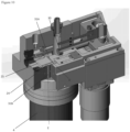
- Figs.9 to 14 illustrate a first aspect of the high pressure/high flow switch of the present disclosure, wherein the high pressure/high flow switch is by way of a pressure driven spool.
- This form of the high pressure/high flow switch can be used in both the side-by-side and top-bottom configurations of grease gun 1.
- the body 3 of grease gun 1 further contains spool channel 22 (also referred to as first channel 22 or first spool channel 22) which extends along a third axis C.
- Spool channel 22 is boundaried by walls 23.
- third axis C is parallel to first axis A and second axis B, although there is no requirement that it be parallel to these axes.
- Third axis C could form any angle to first axis A and second axis B between parallel and perpendicular.
- Moveable within spool channel 22 is spool 24.
- Spool 24 is configured to move (e.g. translate) between open position and a closed position.
- Spool 24 has a mid-section 26, which is boundaried by first annular ring 27 and second annular ring 28 (see Fig. 11 ).
- Mid-section 26 has a smaller diameter relatively to the diameter of spool channel 22, the diameter of first annular ring 27 and the diameter of the second annular ring 28.
- First annular ring 27 and second annular ring 28 are fitted with high pressure seals and form a liquid-tight engagement with surrounding walls 23 of spool channel 22 such that grease is prevented from passing from pressure channel 25 into mid-section 26 by first annular ring 27 and grease is prevented from passing out of mid-section 26 by first annular ring 27 and second annular ring 28.
- the area between mid-section 26, first annular ring 27, second annular ring 28 and walls 23 forms a communication channel 29.
- a first end 24A of spool 24 will be offset from the first end 22A of spool channel 22 so that grease from pressure channel 25 will flow into the portion of spool channel 22 adjacent the first end 24A of spool 24.
- biasing means shown in the form of a biasing spring 30, although other biasing means are also contemplated.
- Biasing spring 30 is adjacent to second end 24B of spool 24 and biases spool 24 towards the closed position.
- bypass channel 31 is made up of primary bypass channel 31A and secondary bypass channel 31B.
- Primary bypass channel 31A runs between first chamber 6 and spool channel 22 such that when there is grease in first chamber 6, it will flow through primary bypass channel 31A into communication channel 29.
- Secondary bypass channel 31B runs between spool channel 22 and grease barrel 4.
- primary bypass channel axis D and secondary bypass channel axis E are substantially perpendicular to each other and offset from one other with respect to spool channel 22. When grease gun 1 is in an upright position, primary bypass channel axis D will be a horizontal axis and secondary bypass channel axis E will be a vertical axis.
- the section of spool channel 22 that connects to primary bypass channel 31A is spaced apart (e.g. offset) from the second of spool channel 22 that connects to secondary bypass channel 31B. Therefore, any grease from primary bypass channel 31A that passes into spool channel 22 must pass along at least a portion of the length of spool channel 22 before passing into secondary bypass channel 31B.
- communication channel 29 is not located adjacent to secondary bypass channel 31B. This means that communication channel 29 is spaced from, and therefore not in fluid communication with secondary bypass channel 31B. As a result, in the closed position, any grease in communication channel 29 will not pass into secondary bypass channel 31B.
- communication channel 29 is located adjacent secondary bypass channel 31B. This means that it is in fluid communication with secondary bypass channel 31B and any grease in communication channel 29 will pass into secondary bypass channel 31B and then into grease barrel 4.
- Mid-section 26 may also contain cavity 32. As shown in Figs. 13 and 14 , grease will flow from primary bypass channel 31A through cavity 32 into communication channel 29. In a preferred embodiment, cavity 32 will extend through mid-section 26 in the same orientation as primary bypass channel 31A and substantially perpendicular to the orientation of secondary bypass channel 31B. As shown in Figs. 10 and 13 , when spool 24 is in the closed position, although grease can flow along primary bypass channel 31A through cavity 32 into communication channel 29, it will be prevented by secondary annular ring 28 from passing into secondary bypass channel 31B.
- biasing spring 30 biases spool 24 towards the closed position. If there is a blocked greasing point, the grease pressure in outlet chamber 20 will increase with each rotation of crank wheel 2. Due to non-return valve 17, the grease from third chamber 14 is restricted from returning to first chamber 6. However, it is not restricted from passing along pressure channel 25 into spool channel 22. In this way, the grease located between first end 22A of spool channel 22 and first end 24A of spool 24 will be under increased pressure.
- a pre-determined level of pressure for example, a level set to an amount between 1000 psi and 3000psi, preferably between 1500psi and 2500psi, most preferably 2000psi
- the force from this pressure will be greater than the force exerted by biasing spring 30, resulting in spool 24 being moved against biasing spring 30 from the closed position to the open position.
- the pressure from the grease in outlet chamber 20 will keep spool 24 in the open position while grease outlet 21 remains blocked.
- first piston 8 and second piston 9 experience the same back pressure and the actuation of link 10 by battery 38 requires enough force to advance the two pistons against the back pressure.
- bypass channel 31 When bypass channel 31 is in open position, grease in first chamber 6 will follow the path of least resistance through bypass channel 31 back into grease barrel 4. However, an amount of backpressure will still be created in first chamber 6 while first piston 8 advances due to the smaller size of the exit channel out of first chamber 6 (bypass channel 31) compared with the size of the entry channel into first chamber 6 (common grease channel 13). Depending on the backpressure level into first chamber 6, and whether it is sufficient to open non-return valve 17, some or none of the grease in first chamber 6 will pass through non-return valve 17 into third chamber 14. As at least the majority of the grease from first chamber 6 will flow through bypass chamber 31, the battery only requires the force to advance the second piston 9 against the backpressure in second chamber 7, as the backpressure on first piston 8 in first chamber 6 will be minimal.
- the additional pressure able to be provided to second chamber 7 when the grease gun is in high pressure mode can increase the pressure of the grease out of grease outlet 21 to very high levels (for example, up to 10,000psi), which may remove the blockage in the system.
- Figs. 2 to 8 illustrate a second aspect of the high pressure/high flow switch of the present disclosure, wherein the high pressure/high flow switch is by way of a pressure relief bypass valve.
- This form of the high pressure/high flow switch can be used in both the side-by-side and top-bottom configurations of grease gun 1.
- body 3 further comprises secondary grease channel 35.
- Secondary grease channel 35 runs between, and fluidically connects, first chamber 6 and grease barrel 4. It is located forward of common grease channel 13 towards the engaged position of first piston 8.
- Secondary grease channel 35 contains a non-return valve, preferably a spring loaded non-return valve 36 which operates as a hydraulic switching mechanism. When non-return valve 36 is open, it permits the flow of grease through secondary grease channel 35 from first chamber 6 into grease barrel 4 but restricts the flow of grease through secondary grease channel 35 from grease barrel 4 into first chamber 6. By default, non-return valve 36 is closed and it is only opened if the grease in first chamber 6 gets to a certain pre-determined level of pressure that exceeds the biasing force from the spring of non-return valve 36.
- non-return valve 36 When non-return valve 36 is open, the grease gun switches from a high flow mode to a high pressure mode. Because non-return valve 36 is open, most of the grease that enters first chamber 6 through common grease channel 13 will flow back into grease barrel 4 by way of secondary grease channel 35. The amount of grease that will flow back into grease barrel 4 will depend on a number of factors including line backpressure of the system, and the viscosity of the grease. In the high pressure mode, non-return valve 36 opens and shuts at every reciprocation of first piston 8, in response to the pressure generated by the piston itself in first chamber 6 .
- battery 38 only requires the force to advance the second piston 9 against the backpressure in second chamber 7, as the backpressure on first piston 8 in first chamber 6 will be minimal.
- the additional pressure able to be provided to second chamber 7 when the grease gun is in high pressure mode can increase the pressure of the grease out of grease outlet 21 to very high levels (for example, up to and beyond 10,000psi), which will help remove the blockage in the system.
- Figs.15 to 17 illustrate a third aspect of the high pressure/high flow switch of the present disclosure, wherein the high pressure/high flow switch is by way of a gap based bypass.
- This form of the high pressure/high flow switch can be used in both the side-by-side and top-bottom configurations of grease gun 1.
- first chamber 6 and first piston 8 there is a liquid-tight engagement between first chamber 6 and first piston 8, and between second chamber 7 and second piston 9 such that grease is prevented from travelling back alone the respective chamber when the respective piston is advanced within that chamber.
- this can be done by the use of positive seal 8A on first piston 8 and positive seal 9A on second piston.
- the first piston 8 has a smaller diameter than the diameter of first chamber 6 such that a radial gap 48 is formed between first piston 8 and first chamber 6.
- first piston 8 When the pressure within first chamber 6 is less than a predetermined amount, the reciprocation of first piston 8 from the retracted position to the engaged position will push grease within first chamber 6 into third chamber 14. However, when the pressure within first chamber 6 is greater than a predetermined amount, the grease gun will be in high pressure mode and the pressure resulting from any further reciprocation of first piston 8 from the retracted position to the engaged position will force any grease along radial gap 48 in first chamber 6 into common grease channel 13.
- battery 38 only requires the force to advance second piston 9 against the backpressure in second chamber 7, as the backpressure on first piston 8 in first chamber 6 will be minimal. This reduces the power required from battery 38 to power motor 37 and therefore rotate crank wheel 2 due to the relatively smaller force required to advance second piston 9, compared to the force to advance both first piston 8 and second piston 9 together, particularly where there is increased pressure in the system due to a grease blockage.
- the additional pressure able to be provided to second chamber 7 when the grease gun is in high pressure mode can increase the pressure of the grease out of grease outlet 21 to very high levels (for example, up to and beyond 10,000psi), which will help remove the blockage in the system.
- an engagement means on body 3 of grease gun 1 for attachment to corresponding engagement means on grease barrel 4.
- the engagement means on body 3 takes the form of outer collar 39 and inner collar 40.
- Outer collar 39 surrounds, and is axially movable on, inner collar 40, such that it is moveable between a locked position (as shown in Figs.19 to 21 ) and an unlocked position (as shown in Figs.22 to 24 ).
- inner collar 40 In the locked position, inner collar 40 can secure grease barrel 4 to body 3. In the unlocked position, inner collar 40 releases grease barrel 4 from body 3.
- Inner collar 40 comprises collar ball channel 41, which extends around the circumference of inner collar 40.
- collar ball channel 41 Within collar ball channel 41 are one or more (preferably two or more) collar locking balls 42.
- Collar locking balls 42 are located within pockets 43 of collar ball channel 41 and are held in their circumferential location by their locations within pockets 43.
- pockets 43 are open at either side of collar ball channel 41 and are narrower than collar locking balls 42 such that collar locking balls 42 have an engaged position within collar ball channel 41 in which they protrude into the inner side of inner collar 40 and a disengaged position where they instead protrude into the outer side of inner collar 40.
- Outer collar 39 is axially moveable on inner collar 40 by tab 45, which radially extends from the surface of outer collar 39 so it can be engaged by a user to move outer collar 39 between the locked and unlocked positions.
- the inside of tab 45 is engageable with helical path 46 on inner collar 40 such that movement of tab 45 will move outer collar 39 with respect to inner collar 40 in both an axial and a transverse direction.
- outer collar 39 In the locked position, outer collar 39 is located on inner collar 40 in a position adjacent to collar ball channel 41. The movement of outer collar 39 to a position that is adjacent to collar ball channel 41 moves collar locking balls 42 within pockets 43 from their disengaged position to their engaged position.
- outer collar 39 In the unlocked position, outer collar 39 is located on inner collar 40 in a position away from collar ball channel 41. In this position, collar locking balls 42 are in the disengaged position.
- Grease barrel 4 has a circumferential groove 44 which is engageable with collar locking balls 42 of collar ball channel 41.
- Groove 44 is located towards but not at the end of the section of grease barrel 4 that is inserted into inner collar 40.
- collar locking balls 42 Upon further movement of tab 45 to move outer collar 39 from the locked to the unlocked position, collar locking balls 42 will retract within pockets 43 of collar ball channel 41, and retract with respect to groove 44 such that grease barrel 4 can be removed from body 3.
- This embodiment includes a hydraulic switch (pressure relief valve) 50, shown in the form of a non-return valve that enables the gun to switch between high pressure and high flow modes, that is similar to the hydraulic switch described above with respect to Figs. 2 to 8 .
- the hydraulic switch 50 is configured to bypass the flow of grease generated by the large piston back into the barrel when the pressure in the first chamber 6 is above around 3000psi. As will be evident to the skilled addressee, the selection of the pressure could be made to suit a particular application.
- the hydraulic switch 50 is electronically monitored such that a user is able to determine if the hydraulic switch is open or closed.
- This embodiment includes another hydraulic switch (pressure relief valve) 52 that fluidically connects the outlet of the grease gun to the grease barrel 4.
- the hydraulic switch is the ultimate safety valve and is configured to open when the pressure at the outlet reaches the max rated pressure of the gun (e.g. 10,000 psi). The switch is therefore able to cut off the pressure generated by the gun at a maximum safe level (e.g. 10,000 psi).
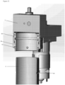
- the hydraulic switch 50 (also referred to as a non-return valve 50) will now be described in further detail with respect to Figs. 26-28.
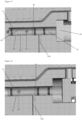
- Figs. 26-28 provide cross sectional views through the gun perpendicular to the pistons and through the hydraulic switch 50.
- the pressure relief valve 50 (also referred to as the first pressure relief valve 50) is configured to open at, for example, 3000psi and then receives grease from the first chamber 6.
- a preloaded e.g.
- spool 54 (also referred to as the first monitoring spool 54) is positioned in a spool chamber 56 (also referred to as a first monitoring channel 56) positioned next to a chamber 58 (also referred to as a first pressure relief channel 58) within which the pressure relief valve 50 is positioned.
- the spool chamber 56 extends along axis X.
- the chamber 58 extends along axis Y. Axis X is spaced from and substantially parallel to the axis Y.
- the spool 54 is biased towards a closed position, whereby the chamber 56 is isolated from the grease barrel (not shown) while being in permanent communication with the chamber 58 via channel 61 (also referred to as connecting channel 61), which is defined by the body 3 and connects chambers 56 and 58.
- Channel 61 is disposed at the lower end of the chambers 56, 58 and extends substantially parallel to the axes X and Y.
- the spool 54 is configured to translate within the chamber 56 along axis X.
- the spool 54 includes a magnet 60 (also referred to as a first magnet 60).
- the magnet 60 is mounted to the spool 54 such that it is configured to be displaced from a rest position, which corresponds with the closed position of the spool 54 (as shown in Figs. 26 and 27 ), towards a displaced position, as shown in Fig. 28 .
- the magnet 60 is mounted to the upper end of the spool 54.
- the spool 54 is configured to be displaced by grease flowing through valve 50.
- a proximity sensor 66 (also referred to as first proximity sensor 66) is disposed above the magnet 60. The proximity sensor 66 is configured to detect the position of the magnet 60, and therefore is able to detect the movements of the spool 54.
- a signal from the proximity sensor 66 is received by a controller (e.g. process control block - PCB).
- the signal provides information about the position of the hydraulic switch (e.g. information indicative of whether the hydraulic switch is in a position that corresponds with high pressure mode, or in a position that corresponds with high flow mode). For example, no signal may represent that the valve 50 is closed and therefore that the grease gun is operating in high flow mode, while a positive signal may represent that the valve 50 is open and therefore the grease gun is operating in high pressure mode.
- the information from the proximity sensor 66 is able to be used by the PCB to determine if grease is actually flowing to the outlet of the grease gun, or just being compressed in the line (e.g.
- valve 50 if valve 50 is open while valve 52 is closed, the gun is in the process of building pressure by compressing the grease against a blockage (dummy greasing), until valve 52 eventually opens up when a max pressure is reached).
- the information can also be used by the electrical system of the grease gun to provide information on the grease gun, such as metering grease output (e.g. meter only in high flow mode and provide no metering in high pressure mode), and to inform a user of a blockage through a LCD display on the grease gun.
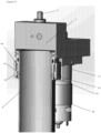
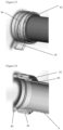
- Figs. 29 and 30 provide cross sectional views through the gun perpendicular to the pistons and through the hydraulic switch 52.
- the pressure relief valve 52 fluidically connects the outlet 68 of the grease gun to the grease barrel.
- valve 52 is fluidically connected to the first 6 and second 7 piston chambers.
- the valve 52 operates as a safety valve and is configured to open when the pressure at the outlet reaches the max rated pressure of the gun (e.g. 10,000 psi).
- the valve 52 may be configured to limit to the maximum pressure that the grease gun is able to generate.
- the valve 52 operates in a similar manner to the valve 50.
- a preloaded (e.g. metal) spool 70 (also referred to as second monitoring spool 70) is positioned in a spool chamber 72 (also referred to as a second monitoring channel 72) positioned next to a chamber 74 (also referred to as a second pressure relief channel 74) within which the pressure relief valve 52 is positioned.
- the spool chamber 72 extends along axis XX.
- the chamber 74 extends along axis YY.
- Axis XX is spaced from and substantially parallel to the axis YY.
- the spool 70 is biased towards a closed position, whereby the chamber 72 is isolated from the grease barrel (not shown) while being in permanent communication with the chamber 74 via channel 76 (also referred to as second connecting channel 76), which is defined by the body 3 and connects chambers 72 and 74.
- Channel 76 is disposed at the lower end of the chambers 72, 74 and extends substantially parallel to the axes XX and YY.
- the spool 70 is configured to translate within the chamber 72 along axis XX.
- a proximity sensor 82 (also referred to as second proximity sensor 82) is disposed above the magnet 78. The proximity sensor 82 is configured to detect the position of the magnet 78, and therefore is able to detect the movements of the spool 72.
- a signal from the proximity sensor 82 is received by a process control block (PCB).
- the signal provides information about the position of the hydraulic switch. For example, no signal may represent that the valve 52 is closed, while a positive signal may represent that the valve 52 is open.
- the information from the proximity sensor 82 is able to be used by the PCB to, for example, inform the user through a LCD display that max pressure was reached and that a blockage could not be cleared.
- the PCB may be configured to cut the grease gun power off after 5 seconds of operating at max pressure and display a warning (e.g. 'dummy greasing') on an LCD display.
- the body 3 of the grease gun may be formed from two separate portions 3A, 3B, where portion 3A is disposed above the actuator 2 in use, and portion 3B is disposed above the barrel 4 in use.
- Splitting the gun body into two septate portions facilitates manufacturing of high accuracy features (e.g. piston chambers) as well as allowing for the use of varying construction materials to best suits the level of mechanical stress required (e.g 'front' housing 3B, which may be subject to high grease pressure and wear and tear from piston reciprocation may be made of steel, while 'rear' housing 3A which supports the motor, gearbox and crank wheel may be made of aluminium).
- the provision of a steel front housing 3B also provides the advantage of more durable outlet check valves (steel balls sit on a steel sealing edge as opposed to, for example, easy to damage aluminium).
Landscapes
- Engineering & Computer Science (AREA)
- General Engineering & Computer Science (AREA)
- Mechanical Engineering (AREA)
- Coating Apparatus (AREA)
- Mechanical Operated Clutches (AREA)
- Valve Device For Special Equipments (AREA)
- Reciprocating Pumps (AREA)
Claims (15)
- Batteriebetriebene Fettpresse (1) umfassend:einen Körper (3), der mit einem zum Speichern von Fett konfigurierten Behälter verbunden werden kann, wobei der Körper (3) eine erste und eine zweite längliche Kammer (6, 7) darin definiert, wobei sich die erste Kammer (6) entlang einer ersten Achse und die zweite Kammer (7) entlang einer zweiten Achse erstreckt, wobei die erste Achse von der zweiten Achse beabstandet ist;einen ersten und einen zweiten Kolben (8, 9), wobei der erste Kolben (8) so konfiguriert ist, dass er sich innerhalb der ersten Kammer (6) entlang der ersten Achse hin und her bewegt, und der zweite Kolben (9) so konfiguriert ist, dass er sich innerhalb der zweiten Kammer (7) entlang der zweiten Achse hin und her bewegt;einen gemeinsamen Fettkanal (13), wobei der gemeinsame Fettkanal (13) zwischen dem Behälter und der ersten und zweiten Kammer (6, 7) angeordnet ist, so dass das Fett aus dem Behälter in die erste und zweite Kammer (6, 7) fließen kann;ein Betätigungselement (2), das mit dem Körper (3) verbunden ist und zwischen einer eingezogenen Position, in der Fett durch den gemeinsamen Fettkanal (13) fließen kann, und einer eingerückten Position, in der Fett daran gehindert wird, durch den gemeinsamen Fettkanal (13) zu fließen, beweglich ist, wobei das Betätigungselement (2) so konfiguriert ist, dass es eine Hin- und Herbewegung des ersten Kolbens (8) und des zweiten Kolbens (9) bewirkt, wenn es zwischen der eingerückten und der eingezogenen Position bewegt wird;einen Fettauslass (21), der mit der ersten und der zweiten Kammer (6, 7) in Fluidverbindung steht und das Ablassen von Fett aus der Fettpresse (1) ermöglicht; dadurch gekennzeichnet, dassdie zweite Kammer (7) eine kleinere Querschnittsfläche als die erste Kammer (6) aufweist;der zweite Kolben (9) eine kleinere Querschnittsfläche als der erste Kolben (8) aufweist;einen ersten Druckentlastungskanal (58), der die erste Kammer (6) mit dem Behälter fluidisch verbindet;ein erstes Druckentlastungsventil (50), das in dem ersten Druckentlastungskanal (58) angeordnet ist, wobei das erste Druckentlastungsventil (50) so konfiguriert ist, dass es sich öffnet und dadurch ermöglicht, dass Fett aus der ersten Kammer (6) in den Behälter fließt, wenn der Druck in der ersten Kammer (6) bei oder über einem vorbestimmten Druck liegt;einen ersten Überwachungskanal (56), der von dem ersten Druckentlastungskanal (58) beabstandet ist;einen Verbindungskanal (61), der den ersten Überwachungskanal (56) strömungstechnisch mit dem ersten Druckentlastungskanal (58) verbindet; undeinen ersten Überwachungsschieber (54), der innerhalb des ersten Überwachungskanals (56) angeordnet ist, wobei der erste Überwachungsschieber (54) so konfiguriert ist, dass er sich innerhalb des ersten Überwachungskanals (56) entlang einer Längsachse des ersten Überwachungskanals (56) zwischen einer geschlossenen und einer offenen Position verschiebt, wobei, wenn sich der erste Überwachungsschieber (54) in der offenen Position befindet, Fett von der ersten Kammer (6) über den Verbindungskanal (61) zu dem Behälter fließen kann.
- Fettpresse (1) nach Anspruch 1, wobei der Fettauslass (21) über eine dritte Kammer (14) mit der ersten Kammer (6) und der zweiten Kammer (7) fluidisch verbunden ist, die mit der ersten Kammer (6) verbunden ist, und eine vierte Kammer (15), die mit der zweiten Kammer (7) verbunden ist, und die erste Kammer (6) über einen ersten Fettkanal (16) mit der dritten Kammer (14) verbunden ist.
- Fettpresse (1) nach Anspruch 2, die ferner ein erstes Rückschlagventil (17) umfasst, das sich in dem ersten Fettkanal (16) befindet und den Fluss von Fett aus der ersten Kammer (6) durch den ersten Fettkanal (16) in die dritte Kammer (14) ermöglicht, und wobei die zweite Kammer (7) über einen zweiten Fettkanal (18) mit der vierten Kammer (15) verbunden ist.
- Fettpresse (1) nach Anspruch 3, die ferner ein zweites Rückschlagventil (19) umfasst, das sich in dem zweiten Fettkanal (18) befindet und den Fluss von Fett aus der zweiten Kammer (7) durch den zweiten Fettkanal (18) in die vierte Kammer (15) ermöglicht.
- Fettpresse (1) nach einem der vorhergehenden Ansprüche, wobei der Körper (3) weiterhin umfasst:einen Schieberkanal (22), der sich entlang einer dritten Achse erstreckt,ein Schieber (24), der innerhalb des Schieberkanals (22) zwischen einer offenen und einer geschlossenen Position beweglich ist; undeinen Bypass-Kanal, der über den Spulenkanal (22) in Fluidverbindung mit der ersten Kammer (6) und dem Behälter steht;wobei der Schieber (24), wenn er sich in der offenen Position befindet, den Fettfluss aus der ersten Kammer (6) zulässt, und wenn der Schieber (24) sich in der geschlossenen Position befindet, den Fettfluss aus der ersten Kammer (6) einschränkt.
- Fettpresse (1) nach Anspruch 5, bei der im Gebrauch der Schieber (24), wenn er sich in der offenen Stellung befindet, den Fettfluss aus der ersten Kammer (6) in den Behälter ermöglicht und, wenn der Schieber (24) sich in der geschlossenen Stellung befindet, den Fettfluss aus der ersten Kammer (6) in den Behälter einschränkt.
- Fettpresse (1) nach Anspruch 6, die außerdem umfasst:einen Druckkanal (25), der an einem ersten Ende (24A) des Schieberkanals (22) angeordnet ist, wobei der Druckkanal (25) in Fluidverbindung mit der dritten Kammer (14) steht; undein Vorspannmittel (30), das an einem zweiten Ende (22B) des Schieberkanals (22) angeordnet ist, wobei das Vorspannmittel (30) so konfiguriert ist, dass es den Schieber (24) in Richtung der geschlossenen Position vorspannt,wobei ein Druckanstieg in der dritten Kammer (14) einen Druckanstieg im Druckkanal (25) und einen daraus resultierenden Druckanstieg am ersten Ende (24A) des Schieberkanals (22) bewirkt, um dadurch den Schieber (24) gegen das Vorspannmittel (30) zu drücken; undwobei bei einem vorbestimmten Druckniveau am ersten Ende (24A) des Schieberkanals (22) der Schieber (24) so konfiguriert ist, dass sie sich in Richtung der offenen Position bewegt.
- Fettpresse (1) nach Anspruch 7, wobei der Bypasskanal einen primären Bypasskanal (31A), der zwischen der ersten Kammer (6) und dem Schieberkanal (22) angeordnet ist, und einen sekundären Bypasskanal (31B) umfasst, der zwischen dem Schieberkanal (22) und dem Behälter angeordnet ist,der primäre Bypasskanal (31A) sich entlang einer primären Bypasskanalachse erstreckt;der sekundäre Bypasskanal (31B) sich entlang einer sekundären Bypasskanalachse erstreckt,wobei die Achse des primären Bypass-Kanals gegenüber der Achse des sekundären Bypass-Kanals in Bezug auf den Schieberkanal (22) versetzt ist und im Wesentlichen senkrecht zur Achse des sekundären Bypass-Kanals verläuft und von dieser beabstandet ist.
- Fettpresse (1) nach Anspruch 8, wobei der Schieberkanal (22) mit dem primären und dem sekundären Bypass-Kanal (31A, 31B) verbunden und zwischen diesen angeordnet ist, so dass, wenn sich der Schieber (24) in der offenen Position befindet, Fett aus dem primären Bypass-Kanal (31A) über den Schieberkanal (22) in den sekundären Bypass-Kanal (31B) fließen kann; und wobei der Schieber (24) Folgendes umfasst:einen ersten ringförmigen Ring (27) und einen zweiten ringförmigen Ring (28), der von dem ersten ringförmigen Ring (27) beabstandet ist; undeinen Mittelteil (26), der zwischen dem ersten und dem zweiten Ring (27, 28) angeordnet ist und von diesen begrenzt wird;wobei der mittlere Abschnitt (26) der Spule (24) einen kleineren Durchmesser hat als der Durchmesser des Schieberkanals (22) und der Durchmesser des ersten und zweiten Ringes (27, 28);wobei ein Bereich, der zwischen dem mittleren Abschnitt (26) dem Schieber (24) und einer Wand des Schieberkanals (22) angeordnet ist, einen Verbindungskanal (29) bildet, wobei der Verbindungskanal (29) in Fluidverbindung mit dem primären Bypass-Kanal (31A) steht, unabhängig davon, ob sich der Schieber (24) in der offenen Position oder in der geschlossenen Position befindet.
- Fettpresse (1) nach Anspruch 9, wobei, wenn sich der Schieber (24) in der geschlossenen Position befindet, der Verbindungskanal (29) nicht neben dem sekundären Bypass-Kanal (31B) angeordnet ist, wodurch der Fettfluss aus dem Spulenkanal (22) in den sekundären Bypass-Kanal (31B) eingeschränkt wird, und wenn sich der Schieber (24) in der offenen Position befindet, der Verbindungskanal (29) neben dem sekundären Bypass-Kanal (31B) angeordnet ist, wodurch der Fettfluss in den sekundären Bypass-Kanal (31B) ermöglicht wird.
- Fettpresse (1) nach Anspruch 10, wobei der Schieber (24) einen Hohlraum (32) aufweist, der sich durch den Schieber (24) erstreckt, wobei der Hohlraum (32) im mittleren Abschnitt (26) des Schiebers (24) angeordnet ist, um zu ermöglichen, dass Fett durch den mittleren Abschnitt (26) des Schiebers (24) fließt und den Verbindungskanal (29) füllt.
- Fettpresse (1) nach Anspruch 1 umfasst außerdem;einen ersten Magneten (60), der an dem ersten Überwachungsschieber (54) angebracht ist;einen Näherungssensor (66), der neben dem ersten Magneten (60) angeordnet ist, wobei der Näherungssensor (66) so konfiguriert ist, dass er ein Signal erzeugt, das die Position des ersten Magneten (60) anzeigt;einen zweiten Druckentlastungskanal (74), der den Auslass (21) mit dem Behälter fluidisch verbindet; undein zweites Druckentlastungsventil (52), das innerhalb des zweiten Druckentlastungskanals (74) angeordnet ist, wobei das zweite Druckentlastungsventil (52) so konfiguriert ist, dass es sich öffnet und dadurch ermöglicht, dass Fett von dem Auslass (21) zu dem Behälter fließt, wenn der Druck in dem Auslass (21) bei oder über einem vorbestimmten Druck liegt.
- Fettpresse (1) nach Anspruch 12 umfasst außerdem;einen zweiten Überwachungskanal (72), der von dem zweiten Druckentlastungskanal (74) beabstandet ist;einen zweiten Verbindungskanal (76), der den zweiten Überwachungskanal (72) mit dem zweiten Druckentlastungskanal (74) fluidisch verbindet; undeinen zweiten Überwachungsschieber (70), der innerhalb des zweiten Überwachungskanals (72) angeordnet ist, wobei der zweite Überwachungsschieber (70) so konfiguriert ist, dass er sich innerhalb des zweiten Überwachungskanals (72) entlang einer Längsachse des zweiten Überwachungskanals (72) zwischen einer geschlossenen und einer offenen Position bewegt, wobei, wenn sich der zweite Überwachungsschieber (70) in der offenen Position befindet, Fett von dem Auslass (21) über den zweiten Verbindungskanal (76) zu dem Behälter fließen kann.
- Fettpresse (1) nach Anspruch 13 umfasst außerdem;einen zweiten Magneten (78), der an dem zweiten Überwachungsschieber (70) angebracht ist; undeinen zweiten Näherungssensor (82), der neben dem zweiten Magneten (78) angeordnet ist, wobei der zweite Näherungssensor (82) so konfiguriert ist, dass er ein Signal erzeugt, das die Position des zweiten Magneten (78) anzeigt.
- Fettpresse (1) nach Anspruch 14 außerdem umfassend;eine Steuerung, die so konfiguriert ist, dass sie die von dem ersten und dem zweiten Näherungssensor (66, 82) erzeugten Signale empfängt, wobei die Steuerung so konfiguriert ist, dass sie Informationen über die Fettpresse (1) in Abhängigkeit von den von dem ersten und dem zweiten Näherungssensor (66, 82) erzeugten Signalen bestimmt; undeine LCD-Anzeige, die so konfiguriert ist, dass sie die bestimmten Informationen anzeigt.
Applications Claiming Priority (2)
| Application Number | Priority Date | Filing Date | Title |
|---|---|---|---|
| US202062991238P | 2020-03-18 | 2020-03-18 | |
| PCT/AU2021/050236 WO2021184068A1 (en) | 2020-03-18 | 2021-03-17 | Battery operated grease gun |
Publications (3)
| Publication Number | Publication Date |
|---|---|
| EP4121685A1 EP4121685A1 (de) | 2023-01-25 |
| EP4121685A4 EP4121685A4 (de) | 2024-04-03 |
| EP4121685B1 true EP4121685B1 (de) | 2025-03-05 |
Family
ID=77767918
Family Applications (1)
| Application Number | Title | Priority Date | Filing Date |
|---|---|---|---|
| EP21769884.4A Active EP4121685B1 (de) | 2020-03-18 | 2021-03-17 | Batteriebetriebene fettpresse |
Country Status (9)
| Country | Link |
|---|---|
| US (1) | US12018796B2 (de) |
| EP (1) | EP4121685B1 (de) |
| JP (1) | JP2023523513A (de) |
| CN (1) | CN115335628A (de) |
| AU (2) | AU2021238896B2 (de) |
| CA (1) | CA3170262A1 (de) |
| TW (1) | TW202140958A (de) |
| WO (1) | WO2021184068A1 (de) |
| ZA (1) | ZA202209250B (de) |
Families Citing this family (1)
| Publication number | Priority date | Publication date | Assignee | Title |
|---|---|---|---|---|
| US20250172240A1 (en) * | 2023-11-23 | 2025-05-29 | Greenworks (Jiangsu) Co., Ltd. | Grease discharging apparatus |
Citations (1)
| Publication number | Priority date | Publication date | Assignee | Title |
|---|---|---|---|---|
| US3682273A (en) * | 1970-10-20 | 1972-08-08 | Eusebe Allard | Lubricating apparatus for heavy machinery |
Family Cites Families (20)
| Publication number | Priority date | Publication date | Assignee | Title |
|---|---|---|---|---|
| US1893738A (en) * | 1926-12-06 | 1933-01-10 | State Holding Co Inc | Grease gun |
| US1775946A (en) * | 1928-10-22 | 1930-09-16 | Paul R Reid | Lubricating apparatus |
| US2051290A (en) * | 1933-01-03 | 1936-08-18 | Stewart Warner Corp | Lubricating apparatus |
| US3291350A (en) * | 1963-11-05 | 1966-12-13 | Jerry P Malec | Fluid pump |
| CH432950A (de) * | 1965-12-14 | 1967-03-31 | Wanner Ag | Schmierpresse mit Entlüftungsvorrichtung |
| CH663834A5 (en) * | 1984-05-11 | 1988-01-15 | Abnox Ag | Grease gun with electro-mechanical actuation - has control valves fitted in cap screwed onto grease reservoir |
| CH666939A5 (de) * | 1985-04-02 | 1988-08-31 | Abnox Ag | Hochdruckfoerdervorrichtung. |
| TW391608U (en) * | 1998-12-30 | 2000-05-21 | Umax Data Systems Inc | Anti-dust mechanism for lens module of image scanner |
| US20070137942A1 (en) * | 2004-06-24 | 2007-06-21 | Weems R M | Battery powered grease gun with strain gauge based pressure transducer |
| TWM273665U (en) * | 2005-03-17 | 2005-08-21 | Tien-Chen Tung | Pressure relief valve structure of a grease gun |
| US7584871B2 (en) | 2006-08-22 | 2009-09-08 | Techway Industrial Co., Ltd. | Grease output device for an electrical grease gun |
| CN101158439A (zh) * | 2006-10-05 | 2008-04-09 | 威姆斯工业有限公司,以莱格西制造公司营业 | 具有基于压力变送器的应变仪的电池动力注油枪 |
| CN201007418Y (zh) * | 2007-02-15 | 2008-01-16 | 刘冬梅 | 手持式电动油脂枪 |
| US8517223B2 (en) * | 2008-05-05 | 2013-08-27 | International Specialties Services, Inc. | Two stage grease gun |
| TWM391608U (en) | 2010-03-31 | 2010-11-01 | Royal Best Group Corp | Improved dual-lug bar grease gun |
| US8517224B2 (en) * | 2011-03-25 | 2013-08-27 | Suction Industrial Co., Ltd. | Oil flow control structure for grease gun |
| CN203215224U (zh) | 2013-04-23 | 2013-09-25 | 杭州云龙机械有限公司 | 高低压黄油枪 |
| WO2017057798A1 (ko) * | 2015-10-02 | 2017-04-06 | 주식회사 아원 | 하이브리드 전원 방식의 자동 그리스 건 |
| US20180030966A1 (en) | 2016-07-28 | 2018-02-01 | Jelley Technology Co., Ltd. | Device of grease gun |
| JP6869807B2 (ja) * | 2017-05-25 | 2021-05-12 | 株式会社マキタ | グリース吐出装置 |
-
2021
- 2021-03-17 CN CN202180022197.7A patent/CN115335628A/zh active Pending
- 2021-03-17 TW TW110109606A patent/TW202140958A/zh unknown
- 2021-03-17 WO PCT/AU2021/050236 patent/WO2021184068A1/en not_active Ceased
- 2021-03-17 EP EP21769884.4A patent/EP4121685B1/de active Active
- 2021-03-17 JP JP2022549858A patent/JP2023523513A/ja active Pending
- 2021-03-17 CA CA3170262A patent/CA3170262A1/en active Pending
- 2021-03-17 US US17/907,966 patent/US12018796B2/en active Active
- 2021-03-17 AU AU2021238896A patent/AU2021238896B2/en active Active
- 2021-10-13 AU AU2021107578A patent/AU2021107578B4/en active Active
-
2022
- 2022-08-17 ZA ZA2022/09250A patent/ZA202209250B/en unknown
Patent Citations (1)
| Publication number | Priority date | Publication date | Assignee | Title |
|---|---|---|---|---|
| US3682273A (en) * | 1970-10-20 | 1972-08-08 | Eusebe Allard | Lubricating apparatus for heavy machinery |
Also Published As
| Publication number | Publication date |
|---|---|
| AU2021238896A9 (en) | 2022-01-20 |
| EP4121685A1 (de) | 2023-01-25 |
| TW202140958A (zh) | 2021-11-01 |
| CN115335628A (zh) | 2022-11-11 |
| ZA202209250B (en) | 2025-02-26 |
| AU2021107578B4 (en) | 2022-03-17 |
| JP2023523513A (ja) | 2023-06-06 |
| WO2021184068A1 (en) | 2021-09-23 |
| US20230131008A1 (en) | 2023-04-27 |
| CA3170262A1 (en) | 2021-09-23 |
| AU2021238896B2 (en) | 2022-07-21 |
| EP4121685A4 (de) | 2024-04-03 |
| US12018796B2 (en) | 2024-06-25 |
| AU2021107578A4 (en) | 2022-01-06 |
| AU2021238896A1 (en) | 2021-11-04 |
Similar Documents
| Publication | Publication Date | Title |
|---|---|---|
| KR101737333B1 (ko) | 어큐뮬레이터 하우징 내에 저장될 수 있는 유체의 양을 펄스식으로 방출하기 위한 디바이스 | |
| EP0743451B1 (de) | Kryopumpe | |
| US4441629A (en) | Compressed gas powered caulking gun | |
| EP0861190B1 (de) | Verfahren und vorrichtung zum aufladen von druckmittelsystemen | |
| US4946077A (en) | In-line air-bleed valve for hand-operated grease guns | |
| EP2769137B1 (de) | Kompakter schmierinjektor und injektorsystem | |
| CN103016427B (zh) | 液压蓄能器 | |
| AU2009281708A1 (en) | Method and apparatus for purging air from automatic lubrication systems | |
| JP2004522905A (ja) | 油圧エネルギ貯蔵システム | |
| AU2021107578B4 (en) | Battery operated grease gun | |
| CN108953968B (zh) | 润滑脂排出装置 | |
| US10273865B2 (en) | Cooling and lubricating system for a piston sealing device | |
| US6962175B2 (en) | Pilot valve operated reciprocating fluid exchange device and method of use | |
| US9062825B2 (en) | Grease gun | |
| US11898696B2 (en) | Grease gun | |
| KR20140005113A (ko) | 윤활 시스템 | |
| AU2014280895B2 (en) | Method and apparatus for purging air from automatic lubrication systems | |
| EP3059488B1 (de) | Ventil mit nachfüllverhindernder vorrichtung für wegwerfbehälter von druckgas | |
| CN101517234A (zh) | 活塞夹头 |
Legal Events
| Date | Code | Title | Description |
|---|---|---|---|
| STAA | Information on the status of an ep patent application or granted ep patent |
Free format text: STATUS: THE INTERNATIONAL PUBLICATION HAS BEEN MADE |
|
| PUAI | Public reference made under article 153(3) epc to a published international application that has entered the european phase |
Free format text: ORIGINAL CODE: 0009012 |
|
| STAA | Information on the status of an ep patent application or granted ep patent |
Free format text: STATUS: REQUEST FOR EXAMINATION WAS MADE |
|
| 17P | Request for examination filed |
Effective date: 20220919 |
|
| AK | Designated contracting states |
Kind code of ref document: A1 Designated state(s): AL AT BE BG CH CY CZ DE DK EE ES FI FR GB GR HR HU IE IS IT LI LT LU LV MC MK MT NL NO PL PT RO RS SE SI SK SM TR |
|
| DAV | Request for validation of the european patent (deleted) | ||
| DAX | Request for extension of the european patent (deleted) | ||
| A4 | Supplementary search report drawn up and despatched |
Effective date: 20240229 |
|
| RIC1 | Information provided on ipc code assigned before grant |
Ipc: F16N 13/14 20060101ALI20240223BHEP Ipc: F16N 13/06 20060101ALI20240223BHEP Ipc: F16N 13/10 20060101ALI20240223BHEP Ipc: F16N 3/12 20060101AFI20240223BHEP |
|
| GRAP | Despatch of communication of intention to grant a patent |
Free format text: ORIGINAL CODE: EPIDOSNIGR1 |
|
| STAA | Information on the status of an ep patent application or granted ep patent |
Free format text: STATUS: GRANT OF PATENT IS INTENDED |
|
| INTG | Intention to grant announced |
Effective date: 20241107 |
|
| GRAS | Grant fee paid |
Free format text: ORIGINAL CODE: EPIDOSNIGR3 |
|
| GRAA | (expected) grant |
Free format text: ORIGINAL CODE: 0009210 |
|
| STAA | Information on the status of an ep patent application or granted ep patent |
Free format text: STATUS: THE PATENT HAS BEEN GRANTED |
|
| AK | Designated contracting states |
Kind code of ref document: B1 Designated state(s): AL AT BE BG CH CY CZ DE DK EE ES FI FR GB GR HR HU IE IS IT LI LT LU LV MC MK MT NL NO PL PT RO RS SE SI SK SM TR |
|
| REG | Reference to a national code |
Ref country code: GB Ref legal event code: FG4D |
|
| REG | Reference to a national code |
Ref country code: CH Ref legal event code: EP |
|
| P01 | Opt-out of the competence of the unified patent court (upc) registered |
Free format text: CASE NUMBER: APP_6354/2025 Effective date: 20250206 |
|
| REG | Reference to a national code |
Ref country code: IE Ref legal event code: FG4D |
|
| REG | Reference to a national code |
Ref country code: DE Ref legal event code: R096 Ref document number: 602021027210 Country of ref document: DE |
|
| PGFP | Annual fee paid to national office [announced via postgrant information from national office to epo] |
Ref country code: DE Payment date: 20250319 Year of fee payment: 5 |
|
| PGFP | Annual fee paid to national office [announced via postgrant information from national office to epo] |
Ref country code: AT Payment date: 20250417 Year of fee payment: 5 |
|
| PG25 | Lapsed in a contracting state [announced via postgrant information from national office to epo] |
Ref country code: RS Free format text: LAPSE BECAUSE OF FAILURE TO SUBMIT A TRANSLATION OF THE DESCRIPTION OR TO PAY THE FEE WITHIN THE PRESCRIBED TIME-LIMIT Effective date: 20250605 |
|
| PG25 | Lapsed in a contracting state [announced via postgrant information from national office to epo] |
Ref country code: FI Free format text: LAPSE BECAUSE OF FAILURE TO SUBMIT A TRANSLATION OF THE DESCRIPTION OR TO PAY THE FEE WITHIN THE PRESCRIBED TIME-LIMIT Effective date: 20250305 |
|
| REG | Reference to a national code |
Ref country code: NL Ref legal event code: MP Effective date: 20250305 |
|
| PG25 | Lapsed in a contracting state [announced via postgrant information from national office to epo] |
Ref country code: ES Free format text: LAPSE BECAUSE OF FAILURE TO SUBMIT A TRANSLATION OF THE DESCRIPTION OR TO PAY THE FEE WITHIN THE PRESCRIBED TIME-LIMIT Effective date: 20250305 |
|
| PGFP | Annual fee paid to national office [announced via postgrant information from national office to epo] |
Ref country code: GB Payment date: 20250423 Year of fee payment: 5 |
|
| REG | Reference to a national code |
Ref country code: LT Ref legal event code: MG9D |
|
| PG25 | Lapsed in a contracting state [announced via postgrant information from national office to epo] |
Ref country code: NO Free format text: LAPSE BECAUSE OF FAILURE TO SUBMIT A TRANSLATION OF THE DESCRIPTION OR TO PAY THE FEE WITHIN THE PRESCRIBED TIME-LIMIT Effective date: 20250605 |
|
| PG25 | Lapsed in a contracting state [announced via postgrant information from national office to epo] |
Ref country code: HR Free format text: LAPSE BECAUSE OF FAILURE TO SUBMIT A TRANSLATION OF THE DESCRIPTION OR TO PAY THE FEE WITHIN THE PRESCRIBED TIME-LIMIT Effective date: 20250305 |
|
| PG25 | Lapsed in a contracting state [announced via postgrant information from national office to epo] |
Ref country code: LV Free format text: LAPSE BECAUSE OF FAILURE TO SUBMIT A TRANSLATION OF THE DESCRIPTION OR TO PAY THE FEE WITHIN THE PRESCRIBED TIME-LIMIT Effective date: 20250305 |
|
| PGFP | Annual fee paid to national office [announced via postgrant information from national office to epo] |
Ref country code: FR Payment date: 20250423 Year of fee payment: 5 |
|
| PG25 | Lapsed in a contracting state [announced via postgrant information from national office to epo] |
Ref country code: GR Free format text: LAPSE BECAUSE OF FAILURE TO SUBMIT A TRANSLATION OF THE DESCRIPTION OR TO PAY THE FEE WITHIN THE PRESCRIBED TIME-LIMIT Effective date: 20250606 Ref country code: BG Free format text: LAPSE BECAUSE OF FAILURE TO SUBMIT A TRANSLATION OF THE DESCRIPTION OR TO PAY THE FEE WITHIN THE PRESCRIBED TIME-LIMIT Effective date: 20250305 |
|
| REG | Reference to a national code |
Ref country code: AT Ref legal event code: MK05 Ref document number: 1773197 Country of ref document: AT Kind code of ref document: T Effective date: 20250305 |
|
| PG25 | Lapsed in a contracting state [announced via postgrant information from national office to epo] |
Ref country code: NL Free format text: LAPSE BECAUSE OF FAILURE TO SUBMIT A TRANSLATION OF THE DESCRIPTION OR TO PAY THE FEE WITHIN THE PRESCRIBED TIME-LIMIT Effective date: 20250305 |
|
| PG25 | Lapsed in a contracting state [announced via postgrant information from national office to epo] |
Ref country code: SE Free format text: LAPSE BECAUSE OF FAILURE TO SUBMIT A TRANSLATION OF THE DESCRIPTION OR TO PAY THE FEE WITHIN THE PRESCRIBED TIME-LIMIT Effective date: 20250305 |
|
| PG25 | Lapsed in a contracting state [announced via postgrant information from national office to epo] |
Ref country code: SM Free format text: LAPSE BECAUSE OF FAILURE TO SUBMIT A TRANSLATION OF THE DESCRIPTION OR TO PAY THE FEE WITHIN THE PRESCRIBED TIME-LIMIT Effective date: 20250305 |
|
| PG25 | Lapsed in a contracting state [announced via postgrant information from national office to epo] |
Ref country code: PT Free format text: LAPSE BECAUSE OF FAILURE TO SUBMIT A TRANSLATION OF THE DESCRIPTION OR TO PAY THE FEE WITHIN THE PRESCRIBED TIME-LIMIT Effective date: 20250707 |
|
| PG25 | Lapsed in a contracting state [announced via postgrant information from national office to epo] |
Ref country code: IT Free format text: LAPSE BECAUSE OF FAILURE TO SUBMIT A TRANSLATION OF THE DESCRIPTION OR TO PAY THE FEE WITHIN THE PRESCRIBED TIME-LIMIT Effective date: 20250305 Ref country code: PL Free format text: LAPSE BECAUSE OF FAILURE TO SUBMIT A TRANSLATION OF THE DESCRIPTION OR TO PAY THE FEE WITHIN THE PRESCRIBED TIME-LIMIT Effective date: 20250305 |
|
| PG25 | Lapsed in a contracting state [announced via postgrant information from national office to epo] |
Ref country code: AT Free format text: LAPSE BECAUSE OF FAILURE TO SUBMIT A TRANSLATION OF THE DESCRIPTION OR TO PAY THE FEE WITHIN THE PRESCRIBED TIME-LIMIT Effective date: 20250305 |
|
| PG25 | Lapsed in a contracting state [announced via postgrant information from national office to epo] |
Ref country code: CZ Free format text: LAPSE BECAUSE OF FAILURE TO SUBMIT A TRANSLATION OF THE DESCRIPTION OR TO PAY THE FEE WITHIN THE PRESCRIBED TIME-LIMIT Effective date: 20250305 Ref country code: EE Free format text: LAPSE BECAUSE OF FAILURE TO SUBMIT A TRANSLATION OF THE DESCRIPTION OR TO PAY THE FEE WITHIN THE PRESCRIBED TIME-LIMIT Effective date: 20250305 |
|
| PG25 | Lapsed in a contracting state [announced via postgrant information from national office to epo] |
Ref country code: RO Free format text: LAPSE BECAUSE OF FAILURE TO SUBMIT A TRANSLATION OF THE DESCRIPTION OR TO PAY THE FEE WITHIN THE PRESCRIBED TIME-LIMIT Effective date: 20250305 |
|
| REG | Reference to a national code |
Ref country code: CH Ref legal event code: H13 Free format text: ST27 STATUS EVENT CODE: U-0-0-H10-H13 (AS PROVIDED BY THE NATIONAL OFFICE) Effective date: 20251024 |
|
| PG25 | Lapsed in a contracting state [announced via postgrant information from national office to epo] |
Ref country code: SK Free format text: LAPSE BECAUSE OF FAILURE TO SUBMIT A TRANSLATION OF THE DESCRIPTION OR TO PAY THE FEE WITHIN THE PRESCRIBED TIME-LIMIT Effective date: 20250305 |
|
| PG25 | Lapsed in a contracting state [announced via postgrant information from national office to epo] |
Ref country code: IS Free format text: LAPSE BECAUSE OF FAILURE TO SUBMIT A TRANSLATION OF THE DESCRIPTION OR TO PAY THE FEE WITHIN THE PRESCRIBED TIME-LIMIT Effective date: 20250705 |
|
| PG25 | Lapsed in a contracting state [announced via postgrant information from national office to epo] |
Ref country code: LU Free format text: LAPSE BECAUSE OF NON-PAYMENT OF DUE FEES Effective date: 20250317 |
|
| REG | Reference to a national code |
Ref country code: DE Ref legal event code: R097 Ref document number: 602021027210 Country of ref document: DE |
|
| REG | Reference to a national code |
Ref country code: BE Ref legal event code: MM Effective date: 20250331 |
|
| PG25 | Lapsed in a contracting state [announced via postgrant information from national office to epo] |
Ref country code: MC Free format text: LAPSE BECAUSE OF FAILURE TO SUBMIT A TRANSLATION OF THE DESCRIPTION OR TO PAY THE FEE WITHIN THE PRESCRIBED TIME-LIMIT Effective date: 20250305 |
|
| PLBE | No opposition filed within time limit |
Free format text: ORIGINAL CODE: 0009261 |
|
| STAA | Information on the status of an ep patent application or granted ep patent |
Free format text: STATUS: NO OPPOSITION FILED WITHIN TIME LIMIT |
|
| PG25 | Lapsed in a contracting state [announced via postgrant information from national office to epo] |
Ref country code: DK Free format text: LAPSE BECAUSE OF FAILURE TO SUBMIT A TRANSLATION OF THE DESCRIPTION OR TO PAY THE FEE WITHIN THE PRESCRIBED TIME-LIMIT Effective date: 20250305 |
|
| REG | Reference to a national code |
Ref country code: CH Ref legal event code: L10 Free format text: ST27 STATUS EVENT CODE: U-0-0-L10-L00 (AS PROVIDED BY THE NATIONAL OFFICE) Effective date: 20260114 |
|
| PG25 | Lapsed in a contracting state [announced via postgrant information from national office to epo] |
Ref country code: BE Free format text: LAPSE BECAUSE OF NON-PAYMENT OF DUE FEES Effective date: 20250331 |
|
| PG25 | Lapsed in a contracting state [announced via postgrant information from national office to epo] |
Ref country code: CH Free format text: LAPSE BECAUSE OF NON-PAYMENT OF DUE FEES Effective date: 20250331 |
|
| PG25 | Lapsed in a contracting state [announced via postgrant information from national office to epo] |
Ref country code: IE Free format text: LAPSE BECAUSE OF NON-PAYMENT OF DUE FEES Effective date: 20250317 |
|
| 26N | No opposition filed |
Effective date: 20251208 |